EP0016137B1 - Prismenfernrohr mit bildstabilisierung - Google Patents
Prismenfernrohr mit bildstabilisierung Download PDFInfo
- Publication number
- EP0016137B1 EP0016137B1 EP79900854A EP79900854A EP0016137B1 EP 0016137 B1 EP0016137 B1 EP 0016137B1 EP 79900854 A EP79900854 A EP 79900854A EP 79900854 A EP79900854 A EP 79900854A EP 0016137 B1 EP0016137 B1 EP 0016137B1
- Authority
- EP
- European Patent Office
- Prior art keywords
- telescope
- prism
- carrier
- telescopes
- binocular
- Prior art date
- Legal status (The legal status is an assumption and is not a legal conclusion. Google has not performed a legal analysis and makes no representation as to the accuracy of the status listed.)
- Expired
Links
- 230000003019 stabilising effect Effects 0.000 title 1
- QNRATNLHPGXHMA-XZHTYLCXSA-N (r)-(6-ethoxyquinolin-4-yl)-[(2s,4s,5r)-5-ethyl-1-azabicyclo[2.2.2]octan-2-yl]methanol;hydrochloride Chemical compound Cl.C([C@H]([C@H](C1)CC)C2)CN1[C@@H]2[C@H](O)C1=CC=NC2=CC=C(OCC)C=C21 QNRATNLHPGXHMA-XZHTYLCXSA-N 0.000 claims description 3
- 230000006641 stabilisation Effects 0.000 abstract description 8
- 238000011105 stabilization Methods 0.000 description 7
- 230000003287 optical effect Effects 0.000 description 6
- 238000013016 damping Methods 0.000 description 2
- 206010044565 Tremor Diseases 0.000 description 1
- 230000006735 deficit Effects 0.000 description 1
- 230000000694 effects Effects 0.000 description 1
- 239000007788 liquid Substances 0.000 description 1
- 210000001747 pupil Anatomy 0.000 description 1
Images
Classifications
-
- G—PHYSICS
- G02—OPTICS
- G02B—OPTICAL ELEMENTS, SYSTEMS OR APPARATUS
- G02B27/00—Optical systems or apparatus not provided for by any of the groups G02B1/00 - G02B26/00, G02B30/00
- G02B27/64—Imaging systems using optical elements for stabilisation of the lateral and angular position of the image
- G02B27/646—Imaging systems using optical elements for stabilisation of the lateral and angular position of the image compensating for small deviations, e.g. due to vibration or shake
Definitions
- the invention relates to a telescope with a gimbal-mounted reversing prism system, the pivot point of the bearing being at the same distance from the objective and eyepiece planes.
- the optical performance of telescopes is severely affected by vibrations that occur while using the telescope.
- DE-C-318 227 describes a device for compensating for vibrations from binoculars. described in which an optical system executes relative movements to the other optical systems when the housing rotates rapidly.
- This document contains an indication that with the device described, two telescopes can also be connected to form a binocular telescope, in which the pivot points of the bearings for the reversing prism systems halve the two normals to the non-coinciding optical axes and in which the two reversing prism systems via their supports are connected.
- a disadvantage of these telescopes is that they require considerable mechanical effort and are very voluminous in the binocular version.
- DE-A-2 419 532 discloses an image stabilization device in which an image reversing prism is gimbally mounted so that the fulcrum is at the same distance from the main lens plane and the main eyepiece plane.
- the invention has for its object to provide a spatial arrangement for the storage of the reverse prism system of a telescope, which allows image stabilization to be achieved with little effort even with a binocular telescope.
- Means for exerting a restoring force and a counterweight for adjusting the equilibrium are advantageously provided for the movable double carrier.
- Rotatable rhombic prism systems arranged in front of the eyepieces can be provided in order to adjust the distance between the eyes of the user.
- the advantages achieved by the invention are, in particular, that a binocular telescope with image stabilization can be built at a reasonable cost and with an acceptable spatial extent.
- the double telescope is easy to implement because it only requires a gimbal for the carrier system.
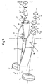
- the optical axes defined by the objectives have the designation 4, 4 'and the optical axes defined by the reversing prism systems 3, 3' have the designation 5, 5 '.
- the axes defined by the eyepieces are labeled 5a, 5a '.
- the prism carrier 6 is movable and rotatably mounted in two directions; its bearings 7 and 8 and axis 17 are visible in the picture. With 9 a fixed, immovable carrier is designated. The attachment of the carrier 9 to the housing is not shown in the illustration. It can take place, for example, via a screw connection.
- the prism carrier 6 is decoupled from the telescope housing in the direction of the Y and Z axes. Since it is rotatably supported in these directions, it can remain spatially fixed with respect to a certain orientation if the telescope moves around the Y or Z axis as a result of vibration.
- the return spring 10 rapidly compensates for the deflection of the carrier 6 that occurs as a result of vibration of the telescope.
- the counterweight 11 enables the carrier system to be set precisely.
- the rhombic prisms 12, 12 ' can be rotated in the direction of 13, 13' to adjust the pupil distance of the user by changing the eyepiece distance.
- the exemplary embodiment of the invention shown has a simple mechanical solution for image stabilization in binocular telescopes, which requires only one bearing, common to both reversing prism systems.
- this embodiment allows higher-order stabilization errors, which, however, can be neglected for normal use.
- the directional effect is exerted by a leaf spring and the damping of the movement by a counterweight damped in air.
- helical or spiral springs or a control loop can be used for directivity
- Position indicators and an electromagnetic actuator are used and to dampen the movement of viscous liquids or an eddy current arrangement.
Landscapes
- Physics & Mathematics (AREA)
- General Physics & Mathematics (AREA)
- Optics & Photonics (AREA)
- Telescopes (AREA)
- Gyroscopes (AREA)
Description
- Die Erfindung betrifft ein Fernrohr mit kardanisch gelagertem Umkehrprismensystem, wobei der Lagerdrehpunkt von der Objektiv- und Okularebene gleichen Abstand hat.
- Die optische Leistungsfähigkeit von Fernrohren wird durch Vibrationen, die während der Benutzung des Fernrohres auftreten, stark beeinträchtigt. Die Beeinträchtigung macht sich umso stärker bemerkbar, je höher die Vergrößerung des Fernrohres ist und führt zum Zittern des Bildes in der Bildebene des Fernrohres.
- In der DE-C-318 227 wird eine Vorrichtung zum Ausgleich von Erschütterungen von Ferngläsern . beschrieben, bei dem ein optisches System bei schnellen Drehbewegungen des Gehäuses Relativbewegungen zu den anderen optischen Systemen ausführt. Diese Schrift enthält einen Hinweis, daß mit der beschriebenen Vorrichtung auch zwei Fernrohre zu einem binokularen Fernrohr verbunden sein können, bei dem die Drehpunkte der Lager für die Umkehrprismensysteme die beiden Normalen zu den nicht zusammenfallenden optischen Achsen halbieren und bei dem die beiden Umkehrprismensysteme über ihre Träger verbunden sind. Nachteilig bei diesen Fernrohren ist, daß sie einen erheblichen mechanischen Aufwand erfordern und in binokularer Ausführung sehr voluminös sind.
- In der DE-A-2 419 532 wird eine Bild-Stabilisierungsvorrichtung offenbart, bei der ein Bildumkehrprisma kardanisch so gelagert ist, daß der Drehpunkt von der Objektivhauptebene und der Okularhauptebene gleichen Abstand hat.
- Das gleiche trifft zu für das in der DE-B-2353101 beschriebene Fernrohr mit Bildstabilisierung. Bei diesen Fernrohren mit Bildstabilisierung ist es aus räumlichen Gründen nicht möglich, das Fernrohr in einer gebrauchsgünstigen Gestaltung binokular auszuführen.
- Der Erfindung liegt die Aufgabe zugrunde, eine räumliche Anordnung für die Lagerung des Umkehrprismensystems eines Fernrohres anzugeben, die es gestattet, mit geringem Aufwand auch bei einem binokularen Fernrohr eine Bildstabilisierung zu erreichen.
- Diese Aufgabe wird erfindungsgemäß dadurch gelöst, daß die Umkehrprismensysteme zweier zu einem binokularen Gerät verbundener Fernrohre an je einem Schenkel eines symmetrisch gegabelten Doppelträgers befestigt sind, der kardanisch um zwei Achsen schwenkbar an einem gehäusefesten, unbeweglichen Träger gelagert ist.
- Vorteilhafterweise sind für den beweglichen Doppelträger Mittel zur Ausübung einer Rückstellkraft und ein Gegengewicht zur Gleichgewichtseinstellung vorgesehen.
- Zur Einstellung des Augenabstandes des Benutzers können vor den Okularen angeordnete, drehbare rhombische Prismensysteme vorgesehen sein.
- Die mit der Erfindung erzielten Vorteile bestehen insbesondere darin, daß mit einem vertretbaren Kostenaufwand und mit annehmbarer räumlicher Ausdehnung ein binokulares Fernrohr mit Bildstabilisierung gebaut werden kann. Das Doppelfernrohr ist leicht ausführbar, da es für das Trägersystem nur ein kardanisches Lager erfordert.
- Ein Ausführungsbeispiel der Erfindung ist in der Zeichnung dargestellt und wird im folgenden näher beschrieben. Es zeigt
- Fig. 1 ein Ausführungsbeispiel des erfindungsgemäßen binokularen Fernrohres in perspektivischer Darstellung.
- Mit 1, 1' sind die Objektive, mit 2, 2' die Okulare und 3, 3' die Umkehrprismensysteme des dargestellten binokularen Fernrohres bezeichnet. Die durch die Objektive definierten optischen Achsen tragen die Bezeichnung 4, 4' und die durch die Umkehrprismensysteme 3, 3' definierten optischen Achsen die Bezeichnung 5, 5'. Die durch die Okulare definierten Achsen tragen die Bezeichnung 5a, 5a'.
- Der Prismenträger 6 ist beweglich und in zwei Richtungen drehbar gelagert; seine Lagerstellen 7 und 8 und die Achse 17 sind in der Abbildung sichtbar. Mit 9 ist ein gehäusefester, unbeweglicher Träger bezeichnet. Die Befestigung des Trägers 9 am Gehäuse ist in der Darstellung nicht gezeichnet. Sie kann beispielsweise über eine Schraubverbindung erfolgen. In Richtung der Y-und Z-Achse ist der Prismenträger 6 vom Fernrohrgehäuse entkoppelt. Da er in diesen Richtungen drehbar gelagert ist, kann er räumlich fest in bezug auf eine bestimmte Ausrichtung stehen bleiben, wenn das Fernrohr sich um die Y- oder Z-Achse infolge einer Vibration bewegt. Die Rückstellfeder 10 bewirkt die rasche Kompensation der infolge Vibration des Fernrohrs erfolgten Auslenkung des Trägers 6. Eine genaue Gleichgewichtseinstellung des Trägersystems ist durch das Gegengewicht 11 möglich. Die rhombischen Prismen 12, 12' sind zur Einstellung der Pupillendistanz des Benutzers durch Änderung des Okularabstandes in Richtung 13,13'drehbar.
- Das gezeigte Ausführungsbeispiel der Erfindung weist eine einfache mechanische Lösung der Bildstabilisierung bei binokularen Fernrohren auf, die nur eine, beiden Umkehrprismensystemen gemeinsame, Lagerstelle erfordert. Allerdings läßt diese Ausführungsform Stabilisierungsfehler höherer Ordnung zu, die jedoch für den normalen Gebrauch vernachlässigt werden können. Die Richwirkung wird durch eine Blattfeder und die Dämfpung der Bewegung durch ein in Luft gedämpftes Gegengewicht ausgeübt. Für die Lösung der Aufgabe ist es auch möglich, andere aus dem Stand der Technik bekannte Mittel für die Richtwirkung und die Dämpfung zu verwenden. So können beispielsweise zur Richtwirkung Schrauben-oder Spiralfedern, oder ein Regelkreis mit stellungsindikatoren und einem elektromagnetischen Stellglied verwendet werden und zur Dämpfung der Bewegung viskose Flüssigkeiten oder eine Wirbelstromanordnung.
Claims (3)
Applications Claiming Priority (2)
| Application Number | Priority Date | Filing Date | Title |
|---|---|---|---|
| DE2834158A DE2834158C3 (de) | 1978-08-04 | 1978-08-04 | Prismenfernrohr mit Bildstabilisierung |
| DE2834158 | 1978-08-04 |
Publications (2)
| Publication Number | Publication Date |
|---|---|
| EP0016137A1 EP0016137A1 (de) | 1980-10-01 |
| EP0016137B1 true EP0016137B1 (de) | 1983-09-07 |
Family
ID=6046173
Family Applications (1)
| Application Number | Title | Priority Date | Filing Date |
|---|---|---|---|
| EP79900854A Expired EP0016137B1 (de) | 1978-08-04 | 1980-03-11 | Prismenfernrohr mit bildstabilisierung |
Country Status (4)
| Country | Link |
|---|---|
| EP (1) | EP0016137B1 (de) |
| AT (1) | ATE4614T1 (de) |
| DE (1) | DE2834158C3 (de) |
| WO (1) | WO1980000377A1 (de) |
Cited By (1)
| Publication number | Priority date | Publication date | Assignee | Title |
|---|---|---|---|---|
| US9581828B2 (en) | 2012-01-13 | 2017-02-28 | Carl Zeiss Sports Optics Gmbh | Optical system for imaging an object |
Families Citing this family (11)
| Publication number | Priority date | Publication date | Assignee | Title |
|---|---|---|---|---|
| SE431021B (sv) * | 1979-06-14 | 1983-12-27 | Bofors Ab | Automatiskt riktinstrument for en artilleripjes |
| HU188785B (en) * | 1982-03-17 | 1986-05-28 | Magyar Optikai Muevek,Hu | Telescope level |
| DE3843775A1 (de) * | 1988-12-24 | 1990-07-05 | Zeiss Carl Fa | Fernrohr mit bildfeldstabilisierung |
| DE3843776A1 (de) * | 1988-12-24 | 1990-07-05 | Zeiss Carl Fa | Fernrohr mit bildfeldstabilisierung |
| DE3933255C2 (de) * | 1989-10-05 | 1995-12-21 | Knoll Dieter B Dr | Richtungsstabilisiertes Fernrohr |
| US6078436A (en) * | 1997-04-24 | 2000-06-20 | Asahi Kogaku Kogyo Kabushiki Kaisha | Mechanism correcting a trembling of focused image |
| JP2003107369A (ja) * | 2001-09-28 | 2003-04-09 | Pentax Corp | 撮影機能付双眼鏡 |
| DE102005027867A1 (de) * | 2005-06-09 | 2006-12-14 | Hensoldt Ag | Fernglas |
| DE102008026978A1 (de) * | 2008-05-29 | 2009-12-03 | Carl Zeiss Ag | Fernrohr |
| DE102012000859B4 (de) | 2012-01-13 | 2021-05-06 | Carl Zeiss Ag | Binokulare fernoptische Vorrichtung mit Bildstabilisierung |
| DE102012206230A1 (de) | 2012-04-16 | 2013-10-17 | Carl Zeiss Sports Optics Gmbh | Optisches System zur Abbildung eines Objekts |
Family Cites Families (4)
| Publication number | Priority date | Publication date | Assignee | Title |
|---|---|---|---|---|
| DE318227C (de) * | ||||
| US2829557A (en) * | 1950-01-17 | 1958-04-08 | Jensen Homer | Stabilized optical sighting device |
| DE2353101C3 (de) * | 1972-10-25 | 1979-01-18 | Fraser-Volpe Corp., Warrington, Pa. (V.St.A.) | Fernrohr mit Bildstabilisierung |
| DE2419532A1 (de) * | 1973-05-12 | 1974-11-28 | Fuji Photo Optical Co Ltd | Vorrichtung zur stabilisierung einer optischen abbildung |
-
1978
- 1978-08-04 DE DE2834158A patent/DE2834158C3/de not_active Expired
-
1979
- 1979-07-12 AT AT79900854T patent/ATE4614T1/de active
- 1979-07-12 WO PCT/DE1979/000071 patent/WO1980000377A1/de not_active Ceased
-
1980
- 1980-03-11 EP EP79900854A patent/EP0016137B1/de not_active Expired
Cited By (1)
| Publication number | Priority date | Publication date | Assignee | Title |
|---|---|---|---|---|
| US9581828B2 (en) | 2012-01-13 | 2017-02-28 | Carl Zeiss Sports Optics Gmbh | Optical system for imaging an object |
Also Published As
| Publication number | Publication date |
|---|---|
| ATE4614T1 (de) | 1983-09-15 |
| WO1980000377A1 (fr) | 1980-03-06 |
| DE2834158C3 (de) | 1981-03-12 |
| EP0016137A1 (de) | 1980-10-01 |
| DE2834158B2 (de) | 1980-08-07 |
| DE2834158A1 (de) | 1980-02-14 |
Similar Documents
| Publication | Publication Date | Title |
|---|---|---|
| DE2834158C3 (de) | Prismenfernrohr mit Bildstabilisierung | |
| US4925281A (en) | Zoom lens | |
| EP0387723A2 (de) | Optisches Bildstabilisierungsgerät | |
| DE2353101B2 (de) | Fernrohr mit Bildstabilisierung | |
| US2829557A (en) | Stabilized optical sighting device | |
| US4264122A (en) | Binocular observation instrument | |
| US9581828B2 (en) | Optical system for imaging an object | |
| DE102012206230A1 (de) | Optisches System zur Abbildung eines Objekts | |
| JP3166157B2 (ja) | ズーム光学装置 | |
| US3497289A (en) | Prism variable anamorphic optical system | |
| DE1797012A1 (de) | Optisch stabilisierte Teleskopanordnung | |
| US3608995A (en) | Intermediate optical processing stabilizer | |
| DE1547160A1 (de) | Einrichtung zum Stabilisieren des Strahlenganges optischer Geraete | |
| DE19543598B4 (de) | Optische Systeme | |
| DE60018116T2 (de) | Optische Anordnung zur Strahlablenkung mit oberflächenkontourierten Risley-Prismen zur Korrektur von Aberrationen | |
| US4260218A (en) | Stabilized optical system with off-axis stabilizer | |
| US2939363A (en) | Optical sighting device | |
| US4542962A (en) | Image-stabilized optical instrument, such as telescope and cameras | |
| US3437397A (en) | Double-mirror system for optical stabilization | |
| US2518632A (en) | Antioscillation mounting for optical instruments such as telescopes, cameras, and the like | |
| US1936576A (en) | Sighting apparatus | |
| US3127466A (en) | Variable magnification lens system for microscopes | |
| JPS58208720A (ja) | 拡大装置 | |
| DE102013200316A1 (de) | Optisches System zur Abbildung eines Objekts | |
| US2282632A (en) | Scale mounting |
Legal Events
| Date | Code | Title | Description |
|---|---|---|---|
| PUAI | Public reference made under article 153(3) epc to a published international application that has entered the european phase |
Free format text: ORIGINAL CODE: 0009012 |
|
| AK | Designated contracting states |
Designated state(s): AT CH FR GB |
|
| 17P | Request for examination filed | ||
| GRAA | (expected) grant |
Free format text: ORIGINAL CODE: 0009210 |
|
| AK | Designated contracting states |
Designated state(s): AT CH FR GB |
|
| REF | Corresponds to: |
Ref document number: 4614 Country of ref document: AT Date of ref document: 19830915 Kind code of ref document: T |
|
| ET | Fr: translation filed | ||
| PLBE | No opposition filed within time limit |
Free format text: ORIGINAL CODE: 0009261 |
|
| STAA | Information on the status of an ep patent application or granted ep patent |
Free format text: STATUS: NO OPPOSITION FILED WITHIN TIME LIMIT |
|
| 26N | No opposition filed | ||
| PGFP | Annual fee paid to national office [announced via postgrant information from national office to epo] |
Ref country code: GB Payment date: 19980612 Year of fee payment: 20 |
|
| PGFP | Annual fee paid to national office [announced via postgrant information from national office to epo] |
Ref country code: AT Payment date: 19980625 Year of fee payment: 20 |
|
| PGFP | Annual fee paid to national office [announced via postgrant information from national office to epo] |
Ref country code: FR Payment date: 19980629 Year of fee payment: 20 |
|
| PGFP | Annual fee paid to national office [announced via postgrant information from national office to epo] |
Ref country code: CH Payment date: 19980701 Year of fee payment: 20 |
|
| PG25 | Lapsed in a contracting state [announced via postgrant information from national office to epo] |
Ref country code: GB Free format text: LAPSE BECAUSE OF NON-PAYMENT OF DUE FEES Effective date: 19990711 Ref country code: CH Free format text: LAPSE BECAUSE OF EXPIRATION OF PROTECTION Effective date: 19990711 |
|
| PG25 | Lapsed in a contracting state [announced via postgrant information from national office to epo] |
Ref country code: AT Free format text: LAPSE BECAUSE OF EXPIRATION OF PROTECTION Effective date: 19990712 |
|
| REG | Reference to a national code |
Ref country code: GB Ref legal event code: PE20 Effective date: 19990711 |
|
| REG | Reference to a national code |
Ref country code: CH Ref legal event code: PL |