EP0015822B1 - Appareil numérique pour le contrôle de pièces par courants de Foucault - Google Patents
Appareil numérique pour le contrôle de pièces par courants de Foucault Download PDFInfo
- Publication number
- EP0015822B1 EP0015822B1 EP80400266A EP80400266A EP0015822B1 EP 0015822 B1 EP0015822 B1 EP 0015822B1 EP 80400266 A EP80400266 A EP 80400266A EP 80400266 A EP80400266 A EP 80400266A EP 0015822 B1 EP0015822 B1 EP 0015822B1
- Authority
- EP
- European Patent Office
- Prior art keywords
- counter
- frequency
- generator
- output
- oscillator
- Prior art date
- Legal status (The legal status is an assumption and is not a legal conclusion. Google has not performed a legal analysis and makes no representation as to the accuracy of the status listed.)
- Expired
Links
- 230000005284 excitation Effects 0.000 claims description 28
- 238000012937 correction Methods 0.000 claims description 19
- 238000005259 measurement Methods 0.000 claims description 16
- 230000006870 function Effects 0.000 claims description 6
- 238000004458 analytical method Methods 0.000 claims description 5
- 239000010453 quartz Substances 0.000 claims description 5
- VYPSYNLAJGMNEJ-UHFFFAOYSA-N silicon dioxide Inorganic materials O=[Si]=O VYPSYNLAJGMNEJ-UHFFFAOYSA-N 0.000 claims description 5
- 238000004804 winding Methods 0.000 description 22
- 235000021183 entrée Nutrition 0.000 description 16
- 238000005070 sampling Methods 0.000 description 4
- 230000008901 benefit Effects 0.000 description 3
- 239000000696 magnetic material Substances 0.000 description 3
- 239000000463 material Substances 0.000 description 3
- 230000010363 phase shift Effects 0.000 description 3
- 239000002184 metal Substances 0.000 description 2
- 238000009659 non-destructive testing Methods 0.000 description 2
- 241001080024 Telles Species 0.000 description 1
- 240000008042 Zea mays Species 0.000 description 1
- 230000009471 action Effects 0.000 description 1
- 238000000137 annealing Methods 0.000 description 1
- 230000015572 biosynthetic process Effects 0.000 description 1
- 230000008859 change Effects 0.000 description 1
- 238000012512 characterization method Methods 0.000 description 1
- 230000000052 comparative effect Effects 0.000 description 1
- 230000007547 defect Effects 0.000 description 1
- 238000013461 design Methods 0.000 description 1
- 238000001514 detection method Methods 0.000 description 1
- 238000010586 diagram Methods 0.000 description 1
- 238000011156 evaluation Methods 0.000 description 1
- 230000036541 health Effects 0.000 description 1
- 238000010438 heat treatment Methods 0.000 description 1
- 230000006872 improvement Effects 0.000 description 1
- 230000001939 inductive effect Effects 0.000 description 1
- 230000000737 periodic effect Effects 0.000 description 1
- 230000035699 permeability Effects 0.000 description 1
- 230000002250 progressing effect Effects 0.000 description 1
- 239000004065 semiconductor Substances 0.000 description 1
- 230000035945 sensitivity Effects 0.000 description 1
- 238000005482 strain hardening Methods 0.000 description 1
- 239000000126 substance Substances 0.000 description 1
- 238000005496 tempering Methods 0.000 description 1
- 230000007704 transition Effects 0.000 description 1
Images

Classifications
-
- G—PHYSICS
- G01—MEASURING; TESTING
- G01N—INVESTIGATING OR ANALYSING MATERIALS BY DETERMINING THEIR CHEMICAL OR PHYSICAL PROPERTIES
- G01N27/00—Investigating or analysing materials by the use of electric, electrochemical, or magnetic means
- G01N27/72—Investigating or analysing materials by the use of electric, electrochemical, or magnetic means by investigating magnetic variables
- G01N27/82—Investigating or analysing materials by the use of electric, electrochemical, or magnetic means by investigating magnetic variables for investigating the presence of flaws
- G01N27/90—Investigating or analysing materials by the use of electric, electrochemical, or magnetic means by investigating magnetic variables for investigating the presence of flaws using eddy currents
- G01N27/9046—Investigating or analysing materials by the use of electric, electrochemical, or magnetic means by investigating magnetic variables for investigating the presence of flaws using eddy currents by analysing electrical signals
Definitions
- the present invention relates to a digital device for the control of parts by eddy currents. It finds an application in non-destructive testing.
- the receiver winding is in fact composed of two secondary windings connected in opposition, so that the measurement signal is the unbalance voltage of the two windings.
- the measurement is differential if the two windings examine two adjacent areas of the part to be checked; it is absolute if only one of the two windings is in the presence of this part (the second winding then comprises a reference standard part).
- the voltage delivered by the sensor is amplified, then analyzed in its resistive (or real) component X and in its reactive (or imaginary) component Y.
- the alternating voltage delivered by the sensor is then represented on the screen of a cathode ray tube by a point of Cartesian coordinates X and Y.
- the senor delivers, even in the absence of a fault in the part to be checked, a residual voltage which can falsify the measurement.
- auxiliary correction or “balancing” circuit comprises on the one hand, a balancing voltage generator whose frequency is equal to that of the excitation voltage and whose amplitude and phase are adjustable and, on the other hand, a two-way differential amplifier inputs, one receiving the balancing voltage and the other the voltage supplied by the sensor.
- the amplitude and phase of the balancing voltage are adjusted so that in the presence of a part deemed good, the amplifier delivers a zero voltage at least at the excitation frequency.
- a circuit which most often includes two periodic samplers, both working at the frequency of the excitation voltage, but in quadrature with respect to each other. These samplers receive from the excitation voltage generator a control pulse which passes through a delay line, which makes it possible to adjust the sampling instants.
- this means consists of circuits able to calculate quantities of the form X cos 6 - Y sin 0 and X sin 6 + Y cos 6, e being the desired angle of rotation.
- the present invention relates to an apparatus of this type. But it is designed to work preferably in a range of low or very low frequency: from about 1 Hz to about 3 kHz. This range corresponds to two fields of application, the second being more important than the first:
- the device of the invention allows the health control (that is to say, the detection of point faults) of non-magnetic products, but high electrical conductivity. These products can be in the form of tubes, bars, profiles and possibly plates. One can also control, on these same materials, certain dimensional parameters and in particular thicknesses when these are relatively large (several millimeters).
- the measurement is always absolute and comparative: the device is calibrated against a reference part.
- the measurement can be carried out either with two sensors, one of which then receives a reference piece, or with a single sensor comprising two secondary windings, wound in opposite directions with respect to each other, only one of them being directly in the presence of the part to be checked.
- the object of the present invention is to remedy these drawbacks by proposing a particular design for the excitation voltage generator, the correction circuit and the means for controlling the samplers.
- the invention notably uses a digital voltage generator.
- Such a circuit is known per se and described for example in document FR-A-2 298 103 in the case of the excitation of a resonant circuit LC.
- the means used in the invention give the device advantages linked to the increase in the finesse of analysis, to the improvement of the reproducibility of the measurements, to the possibility of carrying out very precise calibrations and finally to the way of orienting the measurement signal.
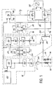
- the operation of the generator 16 is as follows.
- the memory 44 can be of the REPROM (“Reprogrammable Read Only Memory”) type and for example constituted by the IM 6604 circuit sold by the company “INTERSIL”.
- the digital-to-analog converter 46 is intended to operate with an input code of at least eight binary elements. Commercial converters with twelve binary elements can be used, the four least significant binary elements being forced to logic level 1.
- the DAC 1285 circuit for example, from the company "National Semi-conductor" contains such a digital-analog converter and a current-voltage converter.
- the amplifier 48 not forming part of the invention will not be described here. It will simply be indicated that it may be an operational amplifier, for example of the ICH 8520 type from the company "Intersil".
- the correction circuit 18 it firstly comprises a voltage generator 20 whose operation is identical to that which has just been described, since it comprises a set of 56-memory counter 60- converter 62 identical to the counter 42-memory 44- converter 46 assembly. However, this circuit also contains a digital phase shifter, the operation of which is as follows.
- the origin of the phases can be considered as the instant of reset to zero of the counter 42.
- the comparator 52 receives on its inputs E i and E 2 two numbers N 1 and N 2 , the first fixed and determined by the means 50, the second variable and progressing from 0 to 511 with the content of the counter 42.
- N 2 reaches N 1
- the output of comparator 52 changes state and a pulse Ic appears on connection 54.
- This pulse is perfectly set in the cycle 512 shots emitted by oscillator 40. Its position can be adjusted by varying the number Ni selected from 0 to 511. This pulse is used to reset counter 56 and the reset time sets the start and, therefore, the phase of the sinusoid constituting the correction signal.
- the 512 strokes of a cycle thus correspond to a possibility of varying the phase shift of the correction voltage from 360 ° relative to the excitation voltage.
- the phase shift expressed in degrees is therefore equal to 360 ⁇ N l / 512.
- circuit 30 for controlling the samplers its operation is as follows.
- the pulse IX for controlling the sampler 28X is generated in exactly the same way as the pulse Ic for determining the phase of the correction signal. Indeed, the average assembly 70-comparator 72 is identical to the average assembly 50-comparator 52 which has just been described.
- the IY pulse for controlling the sampler 28Y it must be phase shifted by a quarter of a period with respect to the pulse IX.
- control circuit 30 makes it possible not only to generate the two pulses necessary for the control of the samplers, but also to orient the signal appearing on the display screen. This orientation is obtained by modifying the number Ni selected by the means 70.
- This arrangement also has the following advantage. If the measurement signal presents a distortion due to a non-linearity of the magnetic properties of the material in question (for sufficiently large excitation amplitudes) it may be interesting to analyze a particular area of the measurement signal. The apparatus of the invention allows this by adjusting the position of the pulse IX and correlatively of the pulse IY. The choice of the position of the sampling signals then becomes an additional element of analysis.
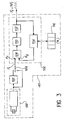
- Fig. 2 shows a particular embodiment of the means 50 and 70 for selecting a number Ni between 0 and C.
- the means represented in this figure comprises an astable oscillator 80 having an adjustable time constant by means of an adjustable resistor 82, a up-down counter 84 connected to this oscillator, a divider 86 by C / 360 followed by a decimal counter 88 connected to a circuit 90 for decoding and controlling a display 92, for example with seven segments.
- the up-down counters are controlled by a key 94 with three positions: up-stop-down-counting.
- the output of the up-down counter84 is applied to the input E i of a comparator (comparator 52 or 72 in fig. 1).
- the divider86 delivers 360 output pulses for 512 input pulses. Each of these pulses therefore represents 0.7 ° of angle. These pulses are totaled in the up-down counter88, the content of which is displayed by the means 92.
- the desired Ni number is obtained by placing the key 94 in the up counting position (or in the down counting position if necessary) to increase (or decrease) ) the number totaled until the number is obtained desired, which is then displayed by means 92 directly in degrees.
- a single astable oscillator 80 can be used for these two means.
- the signal thus brought back has a frequency F 2 .
- the output of oscillator 40 delivers pulses at the frequency Fs.
- the operation of this circuit is conventional.
- the frequency F 1 determined by the oscillator-counter 100 constitutes a reference.
- the phase comparator When the frequency F 2 of the signal fed back to the input e 2 of the phase comparator 108 differs from this reference frequency applied to the input e 1 , the phase comparator generates an error signal which is applied to the oscillator 112, which corrects its frequency until equality between F 1 and F 2 is obtained.
- phase-locked loop 106 a circuit of type 4046 from the company R.C.A. and as a divider a circuit 4059 of the same Company which is a programmable divider with coding wheels. N is then the division factor displayed by the encoder wheels.
- frequency F 1 of the quartz oscillator a frequency expressed in Hertz equal to the capacitance C (or C / 10)
- the frequency F of the excitation generator will always become expressed in Hertz, equal to the division factor N (or N / 10). This frequency then appears directly on the display member 116.
Landscapes
- Chemical & Material Sciences (AREA)
- Chemical Kinetics & Catalysis (AREA)
- Electrochemistry (AREA)
- Physics & Mathematics (AREA)
- Health & Medical Sciences (AREA)
- Life Sciences & Earth Sciences (AREA)
- Analytical Chemistry (AREA)
- Biochemistry (AREA)
- General Health & Medical Sciences (AREA)
- General Physics & Mathematics (AREA)
- Immunology (AREA)
- Pathology (AREA)
- Investigating Or Analyzing Materials By The Use Of Magnetic Means (AREA)
Applications Claiming Priority (2)
| Application Number | Priority Date | Filing Date | Title |
|---|---|---|---|
| FR7906149 | 1979-03-09 | ||
| FR7906149A FR2451032A1 (fr) | 1979-03-09 | 1979-03-09 | Appareil numerique pour le controle de pieces par courants de foucault |
Publications (2)
| Publication Number | Publication Date |
|---|---|
| EP0015822A1 EP0015822A1 (fr) | 1980-09-17 |
| EP0015822B1 true EP0015822B1 (fr) | 1983-03-30 |
Family
ID=9222981
Family Applications (1)
| Application Number | Title | Priority Date | Filing Date |
|---|---|---|---|
| EP80400266A Expired EP0015822B1 (fr) | 1979-03-09 | 1980-02-26 | Appareil numérique pour le contrôle de pièces par courants de Foucault |
Country Status (5)
| Country | Link |
|---|---|
| US (1) | US4322683A (enExample) |
| EP (1) | EP0015822B1 (enExample) |
| JP (1) | JPS55122145A (enExample) |
| DE (1) | DE3062493D1 (enExample) |
| FR (1) | FR2451032A1 (enExample) |
Families Citing this family (29)
| Publication number | Priority date | Publication date | Assignee | Title |
|---|---|---|---|---|
| JPH0338542B2 (enExample) * | 1980-05-22 | 1991-06-11 | Secr Defence Brit | |
| FR2502337A1 (fr) * | 1981-03-23 | 1982-09-24 | Commissariat Energie Atomique | Procede de controle non destructif par courants de foucault avec correction des effets d'entrefer et dispositif de mise en oeuvre |
| US4455529A (en) * | 1981-06-08 | 1984-06-19 | Schlumberger Technology Corporation | Digital induction logging tool including means for measuring phase quadrature components in a phase sensitive detector |
| US4499422A (en) * | 1981-06-08 | 1985-02-12 | Schlumberger Technology Corporation | Digital induction logging tool including means for compensating for phase shift errors |
| US4499421A (en) * | 1981-06-08 | 1985-02-12 | Schlumberger Technology Corporation | Digital induction logging system including means for generating a plurality of transmitter frequencies |
| US4720681A (en) * | 1981-06-08 | 1988-01-19 | Schlumberger Technology Corporation | Digital induction logging tool |
| DE3125732A1 (de) * | 1981-06-30 | 1983-01-13 | Nukem Gmbh, 6450 Hanau | Verfahren und vorrichtung zur werkstoffpruefung nach dem wirbelstromprinzip |
| US4481471A (en) * | 1981-08-14 | 1984-11-06 | Westinghouse Electric Corp. | Method and apparatus for the detection of anomalies in rotating members |
| JPS5858569A (ja) * | 1981-10-02 | 1983-04-07 | Fuji Xerox Co Ltd | 電子複写機のトナ−比率検知装置 |
| BE892243A (fr) * | 1982-02-23 | 1982-06-16 | Dev Et D Industrialisation Des | Appareil de controle par courants de foucault a moyens d'equilibrage electroniques. |
| DE3213267A1 (de) * | 1982-04-08 | 1983-10-20 | Nukem Gmbh, 6450 Hanau | Verfahren und vorrichtung zur pruefung von werkstoffen nach dem wirbelstromprinzip |
| US4709213A (en) * | 1982-07-23 | 1987-11-24 | Garrett Electronics, Inc. | Metal detector having digital signal processing |
| US4620152A (en) * | 1983-01-11 | 1986-10-28 | Amf Tuboscope, Inc. | Lift-off compensation of eddy current probes by translating without rotation the X-Y coordinate plot of the complex locus of the probe output |
| US4599560A (en) * | 1983-04-11 | 1986-07-08 | The Warner & Swasey Company | AC excited transducer having stabilized phase sensitive demodulator circuit |
| FR2570501B1 (fr) * | 1984-09-20 | 1987-12-18 | Siderurgie Fse Inst Rech | Procede de detection de defauts de surface par courants de foucault et dispositif mettant en oeuvre ce procede |
| US4798920A (en) * | 1985-09-06 | 1989-01-17 | Hitachi Seiko, Ltd. | Stylus coordinate determining device with distortion compensation |
| DE3542159A1 (de) * | 1985-11-28 | 1987-06-04 | Nukem Gmbh | Verfahren zur werkstoffpruefung nach dem wirbelstromprinzip und vorrichtung zur durchfuehrung des verfahrens |
| US4755753A (en) * | 1986-07-23 | 1988-07-05 | General Electric Company | Eddy current surface mapping system for flaw detection |
| FR2627862A1 (fr) * | 1988-02-26 | 1989-09-01 | Commissariat Energie Atomique | Procede de controle par courants de foucault impulsionnels et dispositif de mise en oeuvre |
| US6346807B1 (en) * | 1999-10-22 | 2002-02-12 | Bently Nevada Corporation | Digital eddy current proximity system: apparatus and method |
| DE10229735A1 (de) * | 2002-07-02 | 2004-01-22 | rinas Gerätetechnik GmbH | Verfahren zum Erkennen und Lokalisieren von Materialfehlern |
| KR100505929B1 (ko) * | 2003-03-31 | 2005-08-04 | 삼성광주전자 주식회사 | 압축기 및 압축기의 배관연결방법 |
| US7113873B2 (en) * | 2003-11-26 | 2006-09-26 | General Electric Company | Method and system for using eddy current transducers in pressure measurements |
| US7068041B2 (en) * | 2003-11-26 | 2006-06-27 | General Electric Company | Method and system for multi-frequency inductive ratio measurement |
| US6873149B1 (en) | 2003-11-26 | 2005-03-29 | General Electric Company | Method and system for eddy current proximity system noise reduction |
| EP1792173B1 (de) * | 2004-07-19 | 2015-07-08 | Prüftechnik Dieter Busch AG | Vorrichtung und Verfahren zur Erkennung von Defekten an Gegenständen oder zur Ortung von metallischen Objekten |
| JP4756409B1 (ja) | 2011-02-18 | 2011-08-24 | 大日機械工業株式会社 | 交番磁場を利用した非破壊検査装置および非破壊検査方法 |
| WO2015061487A2 (en) * | 2013-10-22 | 2015-04-30 | Jentek Sensors, Inc. | Method and apparatus for measurement of material condition |
| FR3151394A1 (fr) * | 2023-07-20 | 2025-01-24 | Psa Automobiles Sa | Procede de controle de traitement thermique d’un bol de fusee de roue |
Family Cites Families (10)
| Publication number | Priority date | Publication date | Assignee | Title |
|---|---|---|---|---|
| FR1335569A (fr) * | 1962-07-07 | 1963-08-23 | Schlumberger Prospection | Perfectionnements aux appareils de mesure de conductivité par induction |
| US3229198A (en) * | 1962-09-28 | 1966-01-11 | Hugo L Libby | Eddy current nondestructive testing device for measuring multiple parameter variables of a metal sample |
| US3337796A (en) * | 1965-04-19 | 1967-08-22 | Automation Forster Inc | Eddy current testing device with means for sampling the output signal to provide a signal proportional to the instantaneous value of said output signal at a particular phase |
| JPS518347B1 (enExample) * | 1968-06-12 | 1976-03-16 | ||
| CH580811A5 (enExample) * | 1975-01-14 | 1976-10-15 | Sodeco Compteurs De Geneve | |
| US4059795A (en) * | 1976-06-03 | 1977-11-22 | Sensor Corporation | Digital eddy current apparatus for sensing and analyzing metallurgical characteristics of an electrically conductive material |
| US4084136A (en) * | 1976-10-21 | 1978-04-11 | Battelle Memorial Institute | Eddy current nondestructive testing device for measuring variable characteristics of a sample utilizing Walsh functions |
| US4207520A (en) * | 1978-04-06 | 1980-06-10 | The United States Of America As Represented By The Secretary Of The Air Force | Multiple frequency digital eddy current inspection system |
| DE2825958C2 (de) | 1978-06-14 | 1986-02-20 | Institut Dr. Friedrich Förster Prüfgerätebau GmbH & Co KG, 7410 Reutlingen | Magnetisches oder magnetinduktives Werkstoffprüfgerät mit Nullpunktkompensationseinrichtung |
| US4230987A (en) * | 1979-02-26 | 1980-10-28 | Sensor Corporation | Digital eddy current apparatus for generating metallurgical signatures and monitoring metallurgical contents of an electrically conductive material |
-
1979
- 1979-03-09 FR FR7906149A patent/FR2451032A1/fr active Granted
-
1980
- 1980-02-26 EP EP80400266A patent/EP0015822B1/fr not_active Expired
- 1980-02-26 DE DE8080400266T patent/DE3062493D1/de not_active Expired
- 1980-03-03 US US06/126,364 patent/US4322683A/en not_active Expired - Lifetime
- 1980-03-06 JP JP2745480A patent/JPS55122145A/ja active Pending
Also Published As
| Publication number | Publication date |
|---|---|
| FR2451032B1 (enExample) | 1981-10-23 |
| EP0015822A1 (fr) | 1980-09-17 |
| JPS55122145A (en) | 1980-09-19 |
| DE3062493D1 (en) | 1983-05-05 |
| US4322683A (en) | 1982-03-30 |
| FR2451032A1 (fr) | 1980-10-03 |
Similar Documents
| Publication | Publication Date | Title |
|---|---|---|
| EP0015822B1 (fr) | Appareil numérique pour le contrôle de pièces par courants de Foucault | |
| FR2656086A1 (fr) | Systeme a courants de foucault a balayage de frequence pour mesurer l'epaisseur d'un revetement. | |
| EP0012665B1 (fr) | Circuit de correction automatique d'un signal électrique émis par un capteur différentiel déséquilibré | |
| EP0146091B1 (fr) | Méthode et système de test non destructif à courants de Foucault utilisant un balayage en fréquences | |
| EP0179720B1 (fr) | Procédé et dispositif pour mesurer l'épaisseur de couches métalliques minces déposées sur un support conducteur | |
| EP0021893B1 (fr) | Procédé et dispositif d'inspection de produits métalliques par courants de Foucault et application du procédé et du dispositif | |
| FR2587492A1 (fr) | Procede et dispositif pour l'examen non destructif de pieces ferromagnetiques comportant des sections de surfaces qui se raccordent sur des aretes ou des coins, notamment de pieces a symetrie de rotation | |
| EP0335757B1 (fr) | Procédé de contrôle par courants de Foucault impulsionnels et dispositif de mise en oeuvre | |
| Harms et al. | Vibrating reed apparatus with optical detection and digital signal processing: application to measurements on thin films | |
| EP0136238B1 (fr) | Dispositif pour mesurer la proximite d'une surface metallique conductrice | |
| CA3015291C (fr) | Dispositif detecteur inductif de facteur 1 | |
| FR2726369A1 (fr) | Procede de mesure du declin de potentiel et de la mobilite electronique d'un materiau | |
| EP0227767A1 (fr) | Procede et dispositif de determination en volume de la teneur en composant magnetique d'un materiau | |
| EP0061956B1 (fr) | Procédé de contrôle non destructif par courants de Foucault avec correction des effets d'entrefer et dispositif de mise en oeuvre | |
| EP0492392B1 (fr) | Dispositif de contrÔle non destructif à courants de Foucault | |
| Tracy | Surface Chemical Analysis by Auger Electron Spectroscopy and Appearance Potential Spectroscopy: A Comparison | |
| EP0381596B1 (fr) | Procédé et appareil de mesure de capacités de faible valeur | |
| EP0359598B1 (fr) | Procédé de caractérisation de matériaux pour leur utilisation en magnétométrie à résonance, spectromètre pour cette caractérisation et procédé de calibration de ce spectromètre | |
| EP0469267B1 (fr) | Procédé et capteur pour la mesure en continu de l'épaisseur d'un revêtement | |
| Kasap et al. | Application of the interrupted field time-of-flight transient photoconductivity technique to investigating sample inhomogeneities: Cl-doped amorphous Se: Te and Se: As films | |
| FR2607935A1 (fr) | Dispositif et methode de mesure de la difference de potentiel de volta d'un materiau relativement a un materiau de reference | |
| FR2764987A1 (fr) | Procede et dispositif pour la detection et la localisation de defauts dans une piece en materiau composite | |
| Seah et al. | Quantitative AES and XPS: calibration of electron spectrometers for true spectral measurements—VAMAS round robins and parameters for reference spectral data banks | |
| FR2607934A1 (fr) | Methode et dispositif de mesure de la difference de potentiel de volta d'un materiau relativement a un materiau de reference | |
| BE560384A (enExample) |
Legal Events
| Date | Code | Title | Description |
|---|---|---|---|
| PUAI | Public reference made under article 153(3) epc to a published international application that has entered the european phase |
Free format text: ORIGINAL CODE: 0009012 |
|
| AK | Designated contracting states |
Designated state(s): BE CH DE GB IT |
|
| 17P | Request for examination filed |
Effective date: 19810223 |
|
| ITF | It: translation for a ep patent filed | ||
| GRAA | (expected) grant |
Free format text: ORIGINAL CODE: 0009210 |
|
| AK | Designated contracting states |
Designated state(s): BE CH DE GB IT |
|
| REF | Corresponds to: |
Ref document number: 3062493 Country of ref document: DE Date of ref document: 19830505 |
|
| PGFP | Annual fee paid to national office [announced via postgrant information from national office to epo] |
Ref country code: CH Payment date: 19840206 Year of fee payment: 5 |
|
| PGFP | Annual fee paid to national office [announced via postgrant information from national office to epo] |
Ref country code: BE Payment date: 19840331 Year of fee payment: 5 |
|
| PGFP | Annual fee paid to national office [announced via postgrant information from national office to epo] |
Ref country code: DE Payment date: 19850126 Year of fee payment: 6 |
|
| PG25 | Lapsed in a contracting state [announced via postgrant information from national office to epo] |
Ref country code: CH Effective date: 19890228 Ref country code: BE Effective date: 19890228 |
|
| PGFP | Annual fee paid to national office [announced via postgrant information from national office to epo] |
Ref country code: GB Payment date: 19890228 Year of fee payment: 10 |
|
| BERE | Be: lapsed |
Owner name: COMMISSARIAT A L'ENERGIE ATOMIQUE ETS DE CARACTER Effective date: 19890228 |
|
| REG | Reference to a national code |
Ref country code: CH Ref legal event code: PL |
|
| PG25 | Lapsed in a contracting state [announced via postgrant information from national office to epo] |
Ref country code: DE Effective date: 19891101 |
|
| PG25 | Lapsed in a contracting state [announced via postgrant information from national office to epo] |
Ref country code: GB Effective date: 19900226 |
|
| GBPC | Gb: european patent ceased through non-payment of renewal fee | ||
| PLBE | No opposition filed within time limit |
Free format text: ORIGINAL CODE: 0009261 |
|
| STAA | Information on the status of an ep patent application or granted ep patent |
Free format text: STATUS: NO OPPOSITION FILED WITHIN TIME LIMIT |