EP0015630A1 - Mécanisme de verrouillage de sécurité pour magasin de caméra, et caméra et/ou magasin incorporant un tel mécanisme - Google Patents
Mécanisme de verrouillage de sécurité pour magasin de caméra, et caméra et/ou magasin incorporant un tel mécanisme Download PDFInfo
- Publication number
- EP0015630A1 EP0015630A1 EP80200217A EP80200217A EP0015630A1 EP 0015630 A1 EP0015630 A1 EP 0015630A1 EP 80200217 A EP80200217 A EP 80200217A EP 80200217 A EP80200217 A EP 80200217A EP 0015630 A1 EP0015630 A1 EP 0015630A1
- Authority
- EP
- European Patent Office
- Prior art keywords
- camera
- magazine
- store
- locking mechanism
- mechanism according
- Prior art date
- Legal status (The legal status is an assumption and is not a legal conclusion. Google has not performed a legal analysis and makes no representation as to the accuracy of the status listed.)
- Withdrawn
Links
- 230000007246 mechanism Effects 0.000 title claims abstract description 27
- 230000009471 action Effects 0.000 claims abstract description 9
- 238000003780 insertion Methods 0.000 claims abstract description 8
- 230000037431 insertion Effects 0.000 claims abstract description 8
- 230000001133 acceleration Effects 0.000 claims abstract description 7
- 238000010304 firing Methods 0.000 claims description 2
- 238000006073 displacement reaction Methods 0.000 description 6
- 208000031968 Cadaver Diseases 0.000 description 5
- 229910000831 Steel Inorganic materials 0.000 description 3
- XAGFODPZIPBFFR-UHFFFAOYSA-N aluminium Chemical compound [Al] XAGFODPZIPBFFR-UHFFFAOYSA-N 0.000 description 3
- 229910052782 aluminium Inorganic materials 0.000 description 3
- 230000000694 effects Effects 0.000 description 3
- 238000009434 installation Methods 0.000 description 3
- 238000000034 method Methods 0.000 description 3
- 230000035939 shock Effects 0.000 description 3
- 239000010959 steel Substances 0.000 description 3
- 210000000078 claw Anatomy 0.000 description 2
- 238000005553 drilling Methods 0.000 description 2
- 238000000605 extraction Methods 0.000 description 2
- 239000000463 material Substances 0.000 description 2
- 229910001220 stainless steel Inorganic materials 0.000 description 2
- 239000010935 stainless steel Substances 0.000 description 2
- 230000008901 benefit Effects 0.000 description 1
- 230000005540 biological transmission Effects 0.000 description 1
- 230000000903 blocking effect Effects 0.000 description 1
- 238000002474 experimental method Methods 0.000 description 1
- 230000005484 gravity Effects 0.000 description 1
- 230000009931 harmful effect Effects 0.000 description 1
- 230000006872 improvement Effects 0.000 description 1
- 238000003754 machining Methods 0.000 description 1
- 238000005259 measurement Methods 0.000 description 1
- 230000003287 optical effect Effects 0.000 description 1
- 125000006850 spacer group Chemical group 0.000 description 1
- 230000001360 synchronised effect Effects 0.000 description 1
- 238000012360 testing method Methods 0.000 description 1
Images


Classifications
-
- G—PHYSICS
- G03—PHOTOGRAPHY; CINEMATOGRAPHY; ANALOGOUS TECHNIQUES USING WAVES OTHER THAN OPTICAL WAVES; ELECTROGRAPHY; HOLOGRAPHY
- G03B—APPARATUS OR ARRANGEMENTS FOR TAKING PHOTOGRAPHS OR FOR PROJECTING OR VIEWING THEM; APPARATUS OR ARRANGEMENTS EMPLOYING ANALOGOUS TECHNIQUES USING WAVES OTHER THAN OPTICAL WAVES; ACCESSORIES THEREFOR
- G03B17/00—Details of cameras or camera bodies; Accessories therefor
- G03B17/26—Holders for containing light sensitive material and adapted to be inserted within the camera
Definitions
- the invention relates to a security locking mechanism for a camera store, in particular a camera placed in the cockpit of an aircraft which can be subjected to accelerations of the order of 10 g, said store being separable from the body of the camera.
- the invention applies to a sighting recorder arranged in the cockpit of a fighter aircraft in which the operation of the camera is controlled by the trigger lever of the weapons.
- the retreat of the weapons at the time of the firing can cause on the structure of the aircraft very rapid variations of acceleration which can reach 10 g, g denoting the acceleration of gravity, especially in the direction of flight designated later by direction longitudinal.
- a safety locking mechanism for a camera charger of the type defined in the preamble is known from Utility Certificate No. 2 269 844. It is a flight test measurement camera fixed to the device.
- the locking mechanism described in this document is complex and comprises several tens of parts, some of which are difficult to produce, including a centering device by hollow groove and rod, as well as a locking mechanism comprising a vertically movable button as well as two lateral movement locks.
- the invention proposes to provide a security locking mechanism for a camera magazine which is simple to implement and which can withstand rapid variations in acceleration of the order of 10 g, with maximum displacement between the magazine and the camera body a few hundredths of a millimeter.
- the safety locking mechanism defined in the preamble is remarkable in that it allows, in a simple way, the replacement during the flight by the pilot of a store used by a blank store and comprises for this purpose three fixing points of said store in said body of which at least a first, of a first type, is constituted by the association of a centering foot and a precise bore and at least a second, of a second type, is constituted by a latch articulated on said body, which works against the action of a first spring and cooperates with two juxtaposed chamfers disposed externally in the external wall of said magazine, namely an insertion chamfer and a locking chamfer, a cam integral with said body serving , after setting up the magazine, forcing said lock to press against said locking chamfer according to
- the magazine has the shape of a rectangular parallelepiped and is applied against the camera by a lower face and a front face so that after its installation, camera and magazine form a compact unit.
- the front face of the magazine is fixed to the body of the camera by means of two fixing points of said first type, with centering and bore feet, while its lower face is fixed to said body by means of a attachment point of said second type, with latch and chamfer for insertion and blocking.
- this triangular attachment is reversed, the front face of the store being secured to said body by means of a single attachment point of said first type, while its underside is secured to the body by means of two attachment points. fixation of said second type.
- the reference 1 designates the body of a camera, preferably a sighting recorder intended to be mounted in the cockpit of a fighter aircraft.
- This body has a notch intended to receive a magazine 2 comprising the film to be impressed and represented in FIG. 1b.
- the magazine is of substantially parallelepiped shape_and the body-magazine assembly is designed in such a way that after joining, it also substantially takes the form of a parallelepiped.
- the arrow 3 indicates the direction of sight, called longitudinal direction and which will be considered in the following description as being substantially horizontal.
- the body 1 comprises, in a known manner an optical device 4 with lenses and prisms, this device being completed, inside the upper part 5 of the body by a prism, a mirror and, for example, a shutter plug rotating around of a vertical axis.
- the light beams constituting the image to be recorded strike the film after passing through the openings 6 made in the body and 7 in the magazine, following the longitudinal direction indicated by the arrow 8 (FIG. 1a).
- the magazine has a front face 9 and a bottom face 10.
- the front face of the magazine has two bores 11 and 12 located near the side edges and intended to cooperate with two centering feet 13 and 14 located opposite in the body of the camera, during installation, so as to constitute two fixing points of a first type.
- the centering feet 13 and 14 can also belong to the magazine, the bores 11 and 12 belonging to the body.
- the preferred variant is that shown in FIG. 1.
- the film is driven in a known manner by claw and counter claw by means of a mechanism arranged entirely in the magazine and driven from a motor mechanism arranged in the body. , the transmission of movement between body and store being done using a driving crank 15 provided with a retractable spike 16 (FIG. 1 a) cooperating with a driven crank 17 provided with an opening 18 arranged facing flush with the underside of the store.
- This drive mechanism is synchronized, inside the body, with the valve plug driving mechanism.
- the underside of the magazine comprises, near the rear face, substantially in the middle, a support plate 19 provided with a central notch 20 and whose free edges consist of two juxtaposed chamfers which extend in a direction transverse and among which the introduction chamfer 21 is visible, the locking chamfer 22 being hidden.
- This support plate cooperates with a locking device belonging to the rear face of the body and designated by the global reference 23.
- the device 23 cooperates with the support plate 19 so as to constitute a third attachment point, of a second type.
- It comprises a latch 24 constituted by a cylindrical rod force-fitted through a support yoke 25 itself articulated around a transverse axis inside the body.
- an unlocking lever 26 is fixed against the yoke.
- a cam 27 articulated around a longitudinal axis integral with the body and maneuvered by a button 28 ensures the safety locking after the magazine has been put in place.
- Figure 2 illustrates the placement of the magazine against the camera body. This positioning is done using a single hand which grips the magazine by its upper face by pinching its lateral edges.
- the opening 7 (FIG. 1b) to be made in a hollow part (respectively in relief) of substantially frustoconical shape on the front face 9 of the magazine, this part cooperating with a shape identical relief (respectively hollow) practiced in the body of the camera at the location of the opening 6.
- Such hollow or relief parts are not shown in the drawings.
- Such lateral pre-positioning can be supplemented by the fact that the centering feet 13 and 14 as well as the bores 11 and 12 have a cylindrical shape and that their opposite ends have conical shapes.
- the yoke 25 then pivots around the axis 31 and the latch 24 passes from the insertion chamfer 21 to the locking chamfer 22 without ever losing contact with the latter during this movement.
- the insertion chamfer has an inclination of the order of 30 degrees relative to the plane of the support plate.
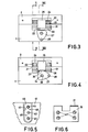
- the end of this movement is illustrated in FIG. 3.
- this last position which is the locking position, the front and bottom faces of the magazine are in contact with the body, the centering feet are fully inserted into the bores and the latch 24 exerts a slight pressure against the locking chamfer under the action of the spring 33. It is then possible to reverse the body-store assembly without the store being detached from the body.
- the cohesive force, calibrated using the spring 33 remains moderate and allows the reversibility of the movement described above, that is to say by taking the magazine by its side faces and exerting on it moderate traction, it can be detached from the body, the yoke pivoting slightly downwards around its axis, which constitutes a possible extraction mode.
- the unlocking lever 26 is therefore not essential and is moreover not shown in FIGS. 3 and 4.
- the direction of this force vector depends on the inclination given to the chamfer 22. This inclination is of the order of 15 degrees relative to the vertical.
- the elements 25 and 27 and more generally the elements constituting the device 23 are preferably made of stainless steel or for example of 30NCll steel.
- the surfaces of the elements 25 and 27 intended to cooperate, in particular the parts 35, 36 and 37 are rectified to better resist wear.
- the maximum tolerated displacement between the film and the optics of the camera is 0.08 mm in order to maintain a clear image.
- This relative fixity is easily obtained when the magazine is an integral part of the camera.
- the magazine is separable as it is here, one imposes a maximum possible displacement between body and magazine of 0,03 mm and the experiment shows that this displacement is sufficiently weak so that the fixity defined above is preserved.
- the precision of 0.03 mm results in a fairly high precision for the relative location of the centering feet and the bores, for their respective diameters as well as for the positioning of the support plate.
- the five elements in question are machined separately for three purposes: firstly the external envelope of the body and that of the magazine being normally made of aluminum, that is to say a material of low mechanical resistance, it is better to make the fixing parts in a harder material, preferably in stainless steel or 30NC11, hardly matte.
- this allows positioning of these elements in two stages as described with reference to FIGS. 5 and 6, namely a presentation between them of the parts simply screwed until obtaining the optimal position then definitive fixing in particular by means of studs pressed by force.
- the replacement of these parts after wear is economical and easy to carry out.
- Figure 5 there is shown a part torn from the front face of the store or the corresponding part of the body, comprising a centering foot or a bore. Consequently, the reference 41 indifferently designates the reference 5 or 9 and the reference 42 one of the references 11, 12, 13 or 14.
- a housing 43 for a positioning bar 44 of steel which is flush on the surface of the wall 41 after being screwed into the latter using two screws 45. A slight clearance of the bar around the screws is provided.
- the machining of the two housings such as 43, for example in the body of the camera is carried out with a dimension of center distance defined with an accuracy of the order of 0.05 mm.
- the bars carrying, for example, the centering feet are then screwed in the middle of these housings and stepped on using studs such as 46 force-fitted through the bar and the underlying wall 41.
- Two housings are also machined in the rear wall of the magazine at the same center distance and with the same precision, then a gauge is used to place the bores carried by the bars linked to the magazine at the same spacing as the centering feet and after obtaining the correct spacing and final screwing, a counter drilling and fixing by hard pressed studs are practiced with the press as before. This way of operating allows very small tolerances between the diameters of the holes and the positioning feet. These tolerances are for example between 8 / u and 12 / u.
- the bores are placed closer to the lower face of the magazine than to its upper face, which guarantees better alignment in the longitudinal direction during the 'introduction.
- the length and diameter of the centering feet and the bores are of the order of 1 to 2 mm. They are linked to the force of the shocks to be transmitted and also depend on the tolerances made between centering feet and bores.
- the support plate can be put in place as described above relative to the bars carrying the bores. Indeed, an adjustment relative to the movement of the lock must be provided. It is also possible to fix the support plate in its housing as shown in Figure 6 for example using four screws 47 blocked in a known manner by loctite after optimal placement.
- the new part When one of the five fixing parts has to be replaced, the new part is provided without the holes for the studs. Its drilling is done through the holes already existing in the aluminum wall of the store or the body after optimal placement.
- the axes respectively supporting the yoke 25 and the cam 27 are integral with a support part machined for this purpose, this part, not shown for the simplification of the drawings, being fixed to the body in a known manner.
- Figures 7 and 8 illustrate an improvement to the embodiment described above, allowing the automatic ejection of the magazine.
- Figure 7 is a view of the store locked against the body, according to section II-II of Figure 3.
- the body further comprises two ejection fingers 51 subjected to a piston movement due to the action of springs not shown which tend to push them from a housing 52. Under the pressure of the rear face of the magazine, these two fingers, located near the lateral edges, penetrate entirely inside their housings.
- the support plate has an additional chamfer 53 at the notch 20, which cooperates with a chamfer 54 formed in an upper edge of the yoke 25.
- the geometry of the different parts is such that when the lever is pressed unlocking 26 starting from the position indicated in FIG.
- FIG. 9 illustrates, in the locked position, a second embodiment of the invention.
- the support plate 19 which, in the first embodiment is comparable to a single fixing point, is replaced by two support plates 55 and 56, fixed with screws and studs in the lower wall of the magazine, near the side edges, and a single centering leg 57 cooperates with a single bore 58 substantially in the middle of the front face of the magazine.
- the lock consists of a rod 59, preferably of hard steel, rotatably supported by two bearings 60 integral with the body of the camera.
- the rod 59 has in its middle a loop 61 acting as a lever and at its ends two cranks 62 and 63 which project outside the body and which are intended to transmit to the ends of the rod 59 constituting the latches proper, the couples exerted on said rod.
- a first moderate locking torque is exerted on the rod by one or two springs, not shown, secured to the body, and a second torque, much higher, is exerted by a safety locking cam 64 actuated by an operating button 65 around. an axis 66.
- the cam 64 has a boss which ends in a flat 67.
Landscapes
- Physics & Mathematics (AREA)
- General Physics & Mathematics (AREA)
- Component Parts Of Construction Machinery (AREA)
- Studio Devices (AREA)
Applications Claiming Priority (2)
| Application Number | Priority Date | Filing Date | Title |
|---|---|---|---|
| FR7906108 | 1979-03-09 | ||
| FR7906108A FR2450747A1 (fr) | 1979-03-09 | 1979-03-09 | Mecanisme de verrouillage de securite pour magasin de camera, et camera et/ou magasin incorporant un tel mecanisme |
Publications (1)
| Publication Number | Publication Date |
|---|---|
| EP0015630A1 true EP0015630A1 (fr) | 1980-09-17 |
Family
ID=9222966
Family Applications (1)
| Application Number | Title | Priority Date | Filing Date |
|---|---|---|---|
| EP80200217A Withdrawn EP0015630A1 (fr) | 1979-03-09 | 1980-03-07 | Mécanisme de verrouillage de sécurité pour magasin de caméra, et caméra et/ou magasin incorporant un tel mécanisme |
Country Status (2)
| Country | Link |
|---|---|
| EP (1) | EP0015630A1 (enExample) |
| FR (1) | FR2450747A1 (enExample) |
Cited By (1)
| Publication number | Priority date | Publication date | Assignee | Title |
|---|---|---|---|---|
| CN109707961A (zh) * | 2018-12-26 | 2019-05-03 | 成都优艾维智能科技有限责任公司 | 一种云台快拆连接结构 |
Citations (6)
| Publication number | Priority date | Publication date | Assignee | Title |
|---|---|---|---|---|
| FR615794A (fr) * | 1926-05-07 | 1927-01-15 | Brachet | Fermeture pour porte de four |
| FR1318120A (fr) * | 1962-03-21 | 1963-02-15 | Loqueteau perfectionné pour fenêtres, portes et articles similaires | |
| FR1397048A (fr) * | 1964-06-03 | 1965-04-23 | Perfectionnements aux dispositifs de fixation pour portes d'armoires et analogues | |
| US3637298A (en) * | 1969-08-11 | 1972-01-25 | Red Lake Lab | Motion-picture camera and the like |
| FR2269844A7 (en) * | 1974-05-02 | 1975-11-28 | Air Ocean | Film pack lock for aircraft flight test camera - has sliding tenons operated by peg depressed by film pack |
| FR2391487A1 (fr) * | 1977-05-20 | 1978-12-15 | Vannet Germaine | Verrouillage de securite pour chargeur de camera |
-
1979
- 1979-03-09 FR FR7906108A patent/FR2450747A1/fr active Granted
-
1980
- 1980-03-07 EP EP80200217A patent/EP0015630A1/fr not_active Withdrawn
Patent Citations (6)
| Publication number | Priority date | Publication date | Assignee | Title |
|---|---|---|---|---|
| FR615794A (fr) * | 1926-05-07 | 1927-01-15 | Brachet | Fermeture pour porte de four |
| FR1318120A (fr) * | 1962-03-21 | 1963-02-15 | Loqueteau perfectionné pour fenêtres, portes et articles similaires | |
| FR1397048A (fr) * | 1964-06-03 | 1965-04-23 | Perfectionnements aux dispositifs de fixation pour portes d'armoires et analogues | |
| US3637298A (en) * | 1969-08-11 | 1972-01-25 | Red Lake Lab | Motion-picture camera and the like |
| FR2269844A7 (en) * | 1974-05-02 | 1975-11-28 | Air Ocean | Film pack lock for aircraft flight test camera - has sliding tenons operated by peg depressed by film pack |
| FR2391487A1 (fr) * | 1977-05-20 | 1978-12-15 | Vannet Germaine | Verrouillage de securite pour chargeur de camera |
Cited By (1)
| Publication number | Priority date | Publication date | Assignee | Title |
|---|---|---|---|---|
| CN109707961A (zh) * | 2018-12-26 | 2019-05-03 | 成都优艾维智能科技有限责任公司 | 一种云台快拆连接结构 |
Also Published As
| Publication number | Publication date |
|---|---|
| FR2450747B1 (enExample) | 1983-03-25 |
| FR2450747A1 (fr) | 1980-10-03 |
Similar Documents
| Publication | Publication Date | Title |
|---|---|---|
| EP1213980B1 (fr) | Dispositif de verrouillage d'une position d'une piece mobile par rapport a une piece fixe | |
| CA2845668A1 (fr) | Systeme mecanique comprenant un dispositif de liaison entre une piece d'usure et son support, godet d'engin de travaux publics et procede de mise en oeuvre d'un tel systeme | |
| EP1034895A1 (fr) | Procédé de pose d'un collier élastique et outillages le mettant en oeuvre | |
| EP0308322A1 (fr) | Appareil de scellement à tir indirect à puissance de tir variable | |
| EP2770094A1 (fr) | Bielle pour un métier à tisser et métier à tisser comprenant cette bielle | |
| EP0002632B1 (fr) | Dispositif de rattrapage d'usure pour frein et frein pourvu de ce dispositif | |
| EP2863273B1 (fr) | Mécanisme d'échappement pour mouvement de montre | |
| EP0015630A1 (fr) | Mécanisme de verrouillage de sécurité pour magasin de caméra, et caméra et/ou magasin incorporant un tel mécanisme | |
| WO1996037749A1 (fr) | Dispositif d'adaptation d'un accessoire d'aide au tir sur une arme a feu individuelle | |
| EP1322805A1 (fr) | Dispositif pour l'accouplement d'un cadre de lisses sur un element de transmission de mouvement, ensemble d'entrainement et metier a tisser equipe d'un tel ensemble | |
| CH652936A5 (fr) | Fixation de securite pour ski. | |
| EP1589313B1 (fr) | Appareil d'équipement accessoire pour chasseur | |
| CH656319A5 (fr) | Fixation de securite pour ski. | |
| EP4415927B1 (fr) | Outil de serrage et de maintien pour des lames de terrasse, de plancher ou de bardage | |
| FR2469249A1 (fr) | Etaux | |
| BE1005385A3 (fr) | Dispositif permettant la reduction du poids de depart de la detente d'une carabine. | |
| FR2473736A1 (fr) | Mecanisme de verrouillage de securite pour magasin de camera et camera et/ou magasin incorporant un tel mecanisme | |
| FR3109141A1 (fr) | Charnière d’articulation entre deux panneaux d’un ensemble propulsif d’aéronef | |
| EP4139625B1 (fr) | Dispositif de mise à feu d'un pistolet | |
| EP0330579A1 (fr) | Dispositif de verrouillage du pivot de barillet d'un revolver | |
| EP0284505A1 (fr) | Dispositif de support pour mécanisme de revolver | |
| EP4080154A1 (fr) | Crosse de fusil de positionnement reglable | |
| EP1155952A1 (fr) | Pédale automatique de cycle | |
| EP0330580A1 (fr) | Dispositif de maintien du pivot de barillet d'un revolver | |
| FR2552495A1 (fr) | Dispositif d'entrainement unidirectionnel a piste exterieure independante |
Legal Events
| Date | Code | Title | Description |
|---|---|---|---|
| PUAI | Public reference made under article 153(3) epc to a published international application that has entered the european phase |
Free format text: ORIGINAL CODE: 0009012 |
|
| AK | Designated contracting states |
Designated state(s): CH DE FR GB IT NL |
|
| STAA | Information on the status of an ep patent application or granted ep patent |
Free format text: STATUS: THE APPLICATION IS DEEMED TO BE WITHDRAWN |
|
| 18D | Application deemed to be withdrawn |
Effective date: 19811117 |
|
| RAP1 | Party data changed (applicant data changed or rights of an application transferred) |
Owner name: KONINKLIJKE PHILIPS ELECTRONICS N.V. Owner name: SOCIETE D'OPTIQUE, DE MECANIQUE D |
|
| RIN1 | Information on inventor provided before grant (corrected) |
Inventor name: LAMOINE, PIERRE ROGER |
|
| RAP1 | Party data changed (applicant data changed or rights of an application transferred) |
Owner name: KONINKLIJKE PHILIPS ELECTRONICS N.V. Owner name: SOCIETE D'OPTIQUE, DE MECANIQUE D |