EP0014429B1 - Device to fasten strand leading segments in a continuous casting plant - Google Patents
Device to fasten strand leading segments in a continuous casting plant Download PDFInfo
- Publication number
- EP0014429B1 EP0014429B1 EP80100468A EP80100468A EP0014429B1 EP 0014429 B1 EP0014429 B1 EP 0014429B1 EP 80100468 A EP80100468 A EP 80100468A EP 80100468 A EP80100468 A EP 80100468A EP 0014429 B1 EP0014429 B1 EP 0014429B1
- Authority
- EP
- European Patent Office
- Prior art keywords
- nut
- base frame
- rod
- semi
- pressure
- Prior art date
- Legal status (The legal status is an assumption and is not a legal conclusion. Google has not performed a legal analysis and makes no representation as to the accuracy of the status listed.)
- Expired
Links
Images

Classifications
-
- B—PERFORMING OPERATIONS; TRANSPORTING
- B22—CASTING; POWDER METALLURGY
- B22D—CASTING OF METALS; CASTING OF OTHER SUBSTANCES BY THE SAME PROCESSES OR DEVICES
- B22D11/00—Continuous casting of metals, i.e. casting in indefinite lengths
- B22D11/12—Accessories for subsequent treating or working cast stock in situ
- B22D11/128—Accessories for subsequent treating or working cast stock in situ for removing
- B22D11/1282—Vertical casting and curving the cast stock to the horizontal
Definitions
- the invention relates to a device for fastening the strand guide segments containing the guide rollers of a sheet continuous casting installation to the base frame of the continuous casting installation by means of multiple fastening bolts.
- a segment is clamped onto the frame with a lever mounted on the base frame, in that the clamping force is applied by a wedge that can be driven in by hand.
- the wedge is driven between the lever and an eccentrically adjustable counterpart which forms the second contact surface for the wedge until there is sufficient jamming.
- the wedge can then be released by pivoting the counterpart of the wedge back by means of an eccentric.
- all work such as swiveling the heavy lever, driving in the wedge, adjusting the eccentric must be carried out in the cramped space of the cooling chamber.
- a further disadvantage is that it can never be determined with certainty which clamping force - which is dependent on different friction values and the impact force of the operator - was ever applied.
- the segment begins to “breathe” on the contact surfaces, which means that there is a possibility that e.g. the sinter sets between the contact surfaces and raises the segment, as a result of which undesired and uncontrollable forces act on the shell of the strand, which in some cases is still very weak, and which can then sometimes lead to strand breakthrough.
- the invention is therefore based on the object to avoid the aforementioned disadvantages and to provide a segment attachment that allows absolutely safe jamming of the segments on the base frame of the continuous casting machine with precisely determinable clamping force without heavy physical work by the operating personnel, the fastening device providing the clamping force lead directly vertically into the circular or circular base frame.
- This object is achieved by the means specified in claim 1.
- the activity of the operating personnel after placing a segment on the base frame of the continuous caster is exhausted by inserting the locking bolt into the sufficiently large rod head bore for coupling with the segment.
- the segment itself is then clamped by acting on the ring cylinder incorporated in the semi-cylindrical pressure piece, which is preferably supplied with grease for reasons of leakage and fire risk via a pump, and in such a way that a precisely predetermined clamping force is applied.
- the ring piston pulls the segment coupled to the pull rod head over the pull rod and the screwed-on nut against which the ring piston rests, defined downwards against the base frame of the continuous caster.
- the clamping force is directly guided vertically into the base frame without redirection, which is made possible in a simple manner by the rotatable thrust piece of semicircular cross-sections used in the transverse bore, since the thrust piece with the pull rod guided therein automatically adjusts itself to the through the circular or Circular arc shape of the continuous caster adapted changes in position and thus the tie rod protrudes vertically from the base frame. Furthermore, the pull rod is always free of bending moments due to the rotational mobility of the semi-cylindrical pressure piece, i.e. only under tension, whatever shifts in the system may occur.
- the bore in the tie rod head can be adjusted in height via the nut acted upon by the ring piston in order to adjust it in alignment with the associated bore in a web-shaped part of the strand guide segment, it is recommended that Drill holes in the tie rod heads larger than the holes in the web-shaped parts of the strand guide segment.
- the semi-cylindrical thrust pieces are expediently secured axially by sealing covers that close the cross holes in the base frame.
- the bearings for the semi-cylindrical thrust pieces and the movable ring piston are thus protected from external influences and are always functional.
- One of the sealing covers carries a supply line for pressure grease, which communicates with a line leading to the pressure chamber of the ring cylinder in the pressure chamber and is provided with a ventilation and non-return valve. In this way, in the event of a segment change in the area of each pull rod, the pressure in the ring cylinder can be selectively released in order to move the locking bolt.
- the operational safety of the fastening device according to the invention also serves when the bores for guiding the locking bolt to the outside are closed by cover hoods, an actuating rod similar to a piston rod being led out of a cover hood for adjusting a locking bolt. This ensures that the locking bolt is always in motion.
- the actual strand guide of the continuous casting installation consists of several strand guide segments which contain a plurality of upper and lower guide rollers 3, 3a and which, according to the circular arc shape of a continuous casting installation, one after the other placed on the base frame 1 forming the supporting structure and fastened to it.
- Each strand guide segment 2 is preferably fixed on the base frame 1 on each side at two fastening points provided at a distance from one another in the strand running direction, thus at a total of four points.
- the entire segment fastening device 4 (FIG. 1) consists of a semi-cylindrical pressure piece 5, in the flat base surface of which a ring cylinder 6 is incorporated, which receives a fitted ring piston 8 sealed with sleeves, in such a way that ring piston 8 and ring cylinder 6 enclose a pressure chamber 9, which can be acted upon by a pressure medium.
- the semi-cylindrical thrust piece 5 also has a through hole which is central to the ring cylinder 6 and is inserted into a transverse bore 11 of the base frame 1, a push rod 12 which projects out of the base frame 1 with the tie rod head 13 having a rod head bore 13a, with the rod end through through Through hole of the semi-cylindrical pressure piece 5 is guided.
- a nut 14 is screwed onto the threaded push rod end 13b (FIG. 2) and serves as a stop for the annular piston 8.
- the pull rod 12 is secured in the area of the exit from the base frame 1 or a mounting element 7 by a seal and simultaneous guide 15 against rotation.
- all rooms that accommodate machined and movable device parts are closed with detachable sealing covers or hoods 16, 16a and 16b.
- the stop nut 14 is accessible by removing one of the sealing covers 16a, which close the transverse bore 11 and axially secure the semi-cylindrical pressure piece 5.
- each fastening device 4 is encapsulated and far from the hot area of the actual strand guide, so that the remote-controlled actuation of the fastening device via the pressure generation in the pressure chambers 9 or its relief is very reliable.
- the ring cylinder 6 is preferably loaded with grease, specifically with a pressure which is precisely determined in advance by means of a pressure-monitored grease pump (not shown in more detail) which can be connected to a nipple 22 of the feed line 22a to the ring cylinder 6.
- a pressure-monitored grease pump (not shown in more detail) which can be connected to a nipple 22 of the feed line 22a to the ring cylinder 6.
- a check valve 23 installed in the grease supply line 22a prevents a drop in pressure in the ring cylinder 6, which is constantly under pressure, should a pipeline break. In the event of a segment change, the pressure in the ring cylinder 6 can be released via a vent valve 24 or via an unlockable check valve or the like.
Abstract
Description
Die Erfindung betrifft eine Vorrichtung zum Befestigen der die Führungsrollen einer Bogen-Stranggießanlage enthaltenden Strangführungssegmente mit dem Grundrahmen der Stranggießanlage mittels mehrfacher Befestigungsbolzen.The invention relates to a device for fastening the strand guide segments containing the guide rollers of a sheet continuous casting installation to the base frame of the continuous casting installation by means of multiple fastening bolts.
Es ist bekannt, eine Stranggießanlage für Metalle in Stranglaufrichtung mit dem grundsätzlichen Aufbau zu gestalten, daß sich auf die Durchlaufgießform der Kokillenhubtisch anschließt, der sich auf das Gerüst der Gießbühne abstützt. An Teilen des Fundamentes bzw. des Gießbühnen-Grundrahmens stützt sich sodann das eigentliche, innerhalb einer Kühlkammer angeordnete Strangführungsgerüst ab, welches in Segmente mit mehreren darin gelagerten sich gegenüberliegenden oberen und unteren Führungsrollen oder -walzen unterteilt ist. Die Segmente, die aus den verschiedensten Gründen wie zum Austausch schadhafter Führungsrollen, zum Einstellen der Führungsrollen auf einen anderen Strang-Querschnitt, etc. oftmals gewechselt werden müssen, sind dabei mittels lösbarer Schraub- oder Keilverbindungen mit den Grundrahmen der Stranggießanlage verbunden (DE-OS-1 957 689).It is known to design a continuous casting system for metals in the direction of the strand with the basic structure that the mold lifting table adjoins the continuous casting mold and is supported on the framework of the casting platform. The actual strand guide frame, which is arranged within a cooling chamber, is then supported on parts of the foundation or the casting platform base frame and is divided into segments with a plurality of opposing upper and lower guide rollers or rollers mounted therein. The segments, which often have to be changed for a variety of reasons, such as to replace damaged guide rollers, to adjust the guide rollers to a different strand cross-section, etc., are connected to the base frame of the continuous casting system by means of detachable screw or wedge connections (DE-OS -1 957 689).
Als nachteilig hat es sich allerdings herausgestellt, daß dann, wenn die Segmente mit dem Grundrahmen verschraubt sind, diese Segmente nur sehr schwierig gegen neue ausgewechselt werden können, weil die Befestigungsschrauben sich während des Betriebes der Anlage derart mit den Muttern verbinden, was durch Einwirkung des auf den Strang gesprühten Kühlwassers noch verstärkt wird, daß ein Lösen der Muttern meistens nur durch Abschneiden mittels Trennschweißverfahren erfolgen kann. Erschwerend wirkt sich dabei aus, daß das Bedienungspersonal diese Arbeiten innerhalb der Kühlkammer und somit in einem sehr beengten und dunklen Raum ausführen muß.It has been found to be disadvantageous, however, that if the segments are screwed to the base frame, it is very difficult to replace these segments with new ones, because the fastening screws connect to the nuts during operation of the system, which is caused by the action of the sprayed onto the strand of cooling water is reinforced that the nuts can usually only be loosened by cutting off using a separating welding process. This is made more difficult by the fact that the operating personnel must carry out this work within the cooling chamber and thus in a very cramped and dark room.
Bei der Keilverbindung wird ein Segment mit einem am Grundrahmen gelagerten Hebel auf dem Rahmen festgeklemmt, indem die Klemmkraft von einem von Hand einschlagbaren Keil aufgebracht wird. Der Keil wird dabei zwischen dem Hebel und einem die zweite Anlagefläche für den Keil bildenden exzenterverstellbaren Gegenstück eingetrieben, bis eine ausreichende Verklemmung vorliegt. Gelöst werden kann der Keil dann dadurch, daß das Gegenstück des Keils mittels Exzenter zurückgeschwenkt wird. Auch hier müssen wieder sämtliche Arbeiten wie Schwenken des schweren Hebels, Einschlagen des Keils, Verstellen des Exzenters, in dem beengten Raum der Kühlkammer durchgeführt werden. Ein weiterer Nachteil ist dadurch gegeben, daß nie mit bestimmtheit angenommen werden kann, welche Klemmkraft - die abhängig Ist von verschiedenen Reibungswerten und der Schlagkraft des bedienungsmannes - überhaupt aufgebracht wurde. Sollte die erforderliche Klemmkraft nicht aufgebracht worden sein, beginnt das Segment an den Auflageflächen zu «atmen», womit die Möglichkeit besteht, daß sich z.B. der Sinter zwischen die Auflageflächen setzt und das Segment anhebt, wodurch unerwünschte und unkontrollierbare Kräfte auf die zum Teil noch sehr schwach ausgebildete Schale des Stranges einwirken, die dann mitunter auch zum Strangdurchbruch führen können.In the wedge connection, a segment is clamped onto the frame with a lever mounted on the base frame, in that the clamping force is applied by a wedge that can be driven in by hand. The wedge is driven between the lever and an eccentrically adjustable counterpart which forms the second contact surface for the wedge until there is sufficient jamming. The wedge can then be released by pivoting the counterpart of the wedge back by means of an eccentric. Again, all work such as swiveling the heavy lever, driving in the wedge, adjusting the eccentric must be carried out in the cramped space of the cooling chamber. A further disadvantage is that it can never be determined with certainty which clamping force - which is dependent on different friction values and the impact force of the operator - was ever applied. If the required clamping force has not been applied, the segment begins to “breathe” on the contact surfaces, which means that there is a possibility that e.g. the sinter sets between the contact surfaces and raises the segment, as a result of which undesired and uncontrollable forces act on the shell of the strand, which in some cases is still very weak, and which can then sometimes lead to strand breakthrough.
Der Erfindung liegt daher die Aufgabe zugrunde, die vorgenannten Nachteile zu vermeiden und eine Segmentbefestigung zu schaffen, die ohne schwere körperliche Arbeit des Bedienungspersonals ein absolut sicheres Verklemmen der Segmente an dem Grundrahmen der Stranggießanlage mit genau im voraus bestimmbarer Klemmkraft ermöglicht, wobei die Befestigungsvorrichtung die Klemmkraft direkt senkrecht in den kreis- bzw. kreisbogenförmigen Grundrahmen führen soll. Diese Aufgabe wird durch die im Anspruch 1 angegebenen Mittel gelöst.The invention is therefore based on the object to avoid the aforementioned disadvantages and to provide a segment attachment that allows absolutely safe jamming of the segments on the base frame of the continuous casting machine with precisely determinable clamping force without heavy physical work by the operating personnel, the fastening device providing the clamping force lead directly vertically into the circular or circular base frame. This object is achieved by the means specified in
Hierdurch wird erreicht, daß sich die Tätigkeit des Bedienungspersonals nach dem Aufsetzen eines Segmentes auf den Grundrahmen der Stranggießanlage darin erschöpft, in die ausreichend große Stangenkopfbohrung zur Kupplung mitdem Segment den Riegelbolzen einzuschieben. Das Festklemmen des Segmentes selbst erfolgt danach durch Beaufschlagung des in das halbzylindrische Druckstück eingearbeitenden Ringzylinders, dem aus Gründen der Leckfreiheit und Brandgefahr über eine Pumpe vorzugsweise Fett zugeführt wird und zwar so, daß eine genau im voraus bestimmte Klemmkraft aufgebracht wird. Damit zieht der Ringkolben nach dem Einschieben des Bolzens das mit dem Zugstangenkopf gekoppelte Segment über die Zugstange und die aufgeschraubte Mutter, gegen die sich der Ringkolben anlegt, definiert nach unten gegen den Grundrahmen der Stranggießanlage. Die Klemmkraft wird dabei ohne Umleitung direkt senkrecht in den Grundrahmen geführt, was durch das in der Querbohrung eingesetzte, drehbewegliche Druckstück halbkreisförmigen Querschnitte auf einfache Art und Weise ermöglicht wird, da sich das Druckstück mit der darin geführten Zugstange automatisch dem durch die Kreis- bzw. Kreisbogenform der Stranggießanlage hervorgerufenen Lageänderungen angepaßt und die Zugstange somit senkrecht aus dem Grundrahmen herausragt. Ferner ist die Zugstange wegen der Drehbeweglichkeit des halbzylindrischen Druckstückes stets frei von Biegemomenten, d.h. nur auf Zug beansprucht, welche Verschiebungen im System sich auch immer einstellen mögen.As a result, the activity of the operating personnel after placing a segment on the base frame of the continuous caster is exhausted by inserting the locking bolt into the sufficiently large rod head bore for coupling with the segment. The segment itself is then clamped by acting on the ring cylinder incorporated in the semi-cylindrical pressure piece, which is preferably supplied with grease for reasons of leakage and fire risk via a pump, and in such a way that a precisely predetermined clamping force is applied. After inserting the bolt, the ring piston pulls the segment coupled to the pull rod head over the pull rod and the screwed-on nut against which the ring piston rests, defined downwards against the base frame of the continuous caster. The clamping force is directly guided vertically into the base frame without redirection, which is made possible in a simple manner by the rotatable thrust piece of semicircular cross-sections used in the transverse bore, since the thrust piece with the pull rod guided therein automatically adjusts itself to the through the circular or Circular arc shape of the continuous caster adapted changes in position and thus the tie rod protrudes vertically from the base frame. Furthermore, the pull rod is always free of bending moments due to the rotational mobility of the semi-cylindrical pressure piece, i.e. only under tension, whatever shifts in the system may occur.
Obwohl die Bohrung in dem Zugstangenkopf über die von dem Ringkolben beaufschlagte Mutter in der Höhe justierbar ist, um sie mit der zugehörrigen Bohrung in einem stegförmigen Teil des Strangführungssegmentes in fluchtende Lage einzustellen, empfiehlt es sich, die Bohrungen in den Zugstangenköpfen größer auszuführen als die Bohrungen in den stegförmigen Teilen des Strangführungssegmentes.Although the bore in the tie rod head can be adjusted in height via the nut acted upon by the ring piston in order to adjust it in alignment with the associated bore in a web-shaped part of the strand guide segment, it is recommended that Drill holes in the tie rod heads larger than the holes in the web-shaped parts of the strand guide segment.
Die halbzylindrischen Druckstücke werden zweckmäßig durch Dichtungsdeckel axial gesichert, die die Querbohrungen im Grundrahmen verschließen. Damit sind die Lagerung für die halbzylindrischen Druckstücke und der bewegliche Ringkolben von äußeren Einflüssen geschützt und stets funktionsfähig.The semi-cylindrical thrust pieces are expediently secured axially by sealing covers that close the cross holes in the base frame. The bearings for the semi-cylindrical thrust pieces and the movable ring piston are thus protected from external influences and are always functional.
Je einer der Dichtungsdeckel trägt eine Zuleitung für Druckfett, die mit einer zum Druckraum des Ringzylinders führenden Leitung im Druckraum kommuniziert und mit einem Entlüftungs-und Rückschlagventil versehen ist. Hierdurch kann im Falle des Segmentwechsels im Bereich einer jeden Zugstange selektiv der Druck in dem Ringzylinder aufgehoben werden, um den Riegelbolzen zu verschieben.One of the sealing covers carries a supply line for pressure grease, which communicates with a line leading to the pressure chamber of the ring cylinder in the pressure chamber and is provided with a ventilation and non-return valve. In this way, in the event of a segment change in the area of each pull rod, the pressure in the ring cylinder can be selectively released in order to move the locking bolt.
Der Betriebssicherheit der Befestigungsvorrichtung gemäß der Erfindung dient es auch, wenn die Bohrungen zur Führung des Riegelbolzens nach außen durch Abdeckhauben verschlossen sind, wobei zur Verstellung eines Riegelbolzens aus einer Abdeckhaube eine kolbenstangenähnliche Betätigungsstange herausgeführt ist. Hierdurch ist sichergestellt, daß der Riegelbolzen stets gängig ist.The operational safety of the fastening device according to the invention also serves when the bores for guiding the locking bolt to the outside are closed by cover hoods, an actuating rod similar to a piston rod being led out of a cover hood for adjusting a locking bolt. This ensures that the locking bolt is always in motion.
In der Zeichnung ist ein Ausführungsbeispiel der Segmentbefestigung gemäß der Erfindung dargestellt. Es zeigt
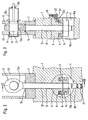
Figur 1 in Stranglaufrichtung gesehen die vereinfachte, teilweise als Schnittzeichnung ausgeführte Darstellung eines mit der erfindungsgemäßen Befestigungsvorrichtung auf den Grundrahmen der Stranggießanlage festgelegten Strangführungssegmentes,- Figur 2 die in den Grundrahmen eingebaute, mit dem Zugstangenkopf herausragende Befestigungsvorrichtung in der Vordersicht, im Schnitt nach der Linie 11-11 in Fig. 1, in vergrößertem Maßstab, und
- Figur 3 die Befestigungsvorrichtung gemäß Fig. 2 im Schnitt nach Linie 111-111 in Fig. 2.
- FIG. 1, seen in the direction of the strand, the simplified representation, partly as a sectional drawing, of a strand guide segment fixed to the base frame of the continuous casting installation using the fastening device according to the invention,
- Figure 2 shows the built in the base frame, with the tie rod head protruding fastening device in the front view, in section along the line 11-11 in Fig. 1, on an enlarged scale, and
- 3 shows the fastening device according to FIG. 2 in section along line 111-111 in FIG. 2nd
Fig. 1 zeigt ein mit dem Grundrahmen 1 einer nicht näher gezeigten Stranggießanlage fest verbundenes rahmenartiges Strangführungssegment 2. Die eigentliche Strangführung der Stranggießanlage besteht dabei aus mehreren, eine Vielzahl von oberen und unteren Führungsrollen 3, 3a enthaltenden Strangführungssegmenten, welche entsprechend der Kreisbogenform einer Stranggießanlage nacheinander auf den die Tragkonstruktion bildenden Grundrahmen 1 aufgesetzt und an diesem zu befestigen sind. Ein jedes Strangführungssegment 2 wird vorzugsweise an jeder Seite an zwei in Stranglaufrichtung mit Abstand zueinander vorgesehenen Befestigungsstellen, somit an insgesamt vier Stellen, auf dem Grundrahmen 1 festgelegt.1 shows a frame-like strand guide segment 2 which is firmly connected to the
Die gesamte Segmentbefestigungsvorrichtung 4 (Fig. 1) besteht aus einem halbzylindrischen Druckstück 5, in dessen ebene Grundfläche ein Ringzylinder 6 eingearbeitet ist, der einen eingepaßten und mit Manschetten abgedichteten Ringkolben 8 aufnimmt, dergestalt, daß Ringkolben 8 und Ringzylinder 6 einen Druckraum 9 einschließen, der von einem Druckmittel beaufschlagbar ist. Das halbzylindrische Druckstück 5 weist weiterhin eine zum Ringzylinder 6 zentrische Durchgangsbohrung auf und ist in eine Querbohrung 11 des Grundrahmens 1 eingesetzt, wobei eine Druckstange 12, die mit dem eine Stangenkopfbohrung 13a aufweisenden Zugstangenkopf 13 aus dem Grundrahmen 1 herausragt, mit dem Stangenende bis durch die Durchgangsbohrung des halbzylindrischen Druckstückes 5 geführt ist. An dem mit Gewinde versehenen Druckstangenende 13b (Fig.2) ist eine Mutter 14 aufgeschraubt, die als Anschlag für den Ringkolben 8 dient. Im übrigen wird die Zugstange 12 im Bereich des Austritts aus dem Grundrahmen 1 bzw. einem Aufsetzelement 7 von einer Abdichtung und gleichzeitigen Führung 15 gegen Verdrehung gesichert. Es sind überhaupt alle Räume, die bearbeitete und bewegliche Vorrichtungsteile aufnehmen, mit lösbaren Dichtungsdeckeln bzw. -hauben 16, 16a und 16b verschlossen.The entire segment fastening device 4 (FIG. 1) consists of a
Die Anschlagmutter 14 ist zugänglich, indem eine der Dichtungsdeckel 16a, die die Querbohrung 11 verschließen und das halbzylindrische Druckstück 5 axial sichern, abgenommen wird.The
Die Beweglichkeit des Druckstückes 5 aufgrund seiner halbzylindrischen Anlagefläche in der Querbohrung 11 und einer Durchgangsbohrung 10 im Grundrahmen 1, die im Durchmesser größer ist als der Durchmesser der Zugstange 12, ermöglicht es, daß der Ringkolben 8 stets verkantungsfrei an der Mutter 14 anliegt und die Zugstange nicht auf Biegung beansprucht wird. Es erübrigt sich also, an dem gebogenen Grundrahmen für alle Befestigungsbolzen jeweils Sitzflächen für Spannmuttern anzufräsen, die genau quer zu den durch die Bogenform des Grundrahmens notwendigerweise unter sich unparallelen Bolzen verlaufen müßten. Im übrigen liegt jede Befestigungsvorrichtung 4 eingekapselt und weit entfernt vom heißen Bereich der eigentlichen Strangführung, so daß die ferngesteuerte Betätigung der Befestigungsvorrichtung über die Druckerzeugung in den Druckräumen 9 oder deren Entlastung sehr funktionssicher ist.The mobility of the
Die Wirkungsweise der beschriebenen Befestigungsvorrichtung ist folgende :
- In entspannter Stellung, d.h., wenn der Druck im
Ringzylinder 6 abgelassen ist, drückt eineFeder 17 entweder direkt auf das untere freie Stirnende einerZugstange 12 oder über einen zwischengeschalteten Kolben 18 (Fig. 2), der dieMutter 14 mitZugstange 12 nachhaltig nach oben gegen die Grundfläche deshalbzylindrischen Druckstückes 5 drückt. DieFeder 17 ist dabei so stark, daß dieZugstange 12 sicher um das durch dieMutter 14 bestimmte Maß angehoben wird. In dieser Stellung, die die Aufsetzstellung für einstegförmiges Segmentrahmenteil 10 eines Strangführungssegmentes 2 ist, ragt dieZugstange 12 so weit aus demGrundrahmen 1 heraus, daß derZugstangenkopf 13 mit derStangenkopfbohrung 13 a nach dem Aufsetzen desRahmenteils 20 auf denGrundrahmen 1 bzw. einAufsetzelement 7 mit einerentsprechenden Bohrung 19 desSegmentrahmenteils 20 fluchtet, was noch durch Justieren derMutter 14 beinflußt werden kann. Sobald diese Position erreicht ist, wird zur Kupplung desSegmentrahmenteiles 20 mit demGrundrahmen 1 einRiegelbolzen 21 durch dieBohrung 19 desSegmentrahmenteiles 20 und durch dieStangenkopfbohrung 13a eingeschoben, was ohne große Kraftanstrengung erfolgt, da derRiegelbolzen 21 gegenüber denBohrungen Dichtungshaube 16b eine kolbenstangenähnliche Betätigungsstange herausgeführt.
- In a relaxed position, that is, when the pressure in the
ring cylinder 6 is released, aspring 17 presses either directly onto the lower free end of apull rod 12 or via an intermediate piston 18 (FIG. 2), which thenut 14 with thepull rod 12 sustained presses against the base of thesemi-cylindrical pressure piece 5 above. Thespring 17 is so strong that thetie rod 12 is safely raised by the amount determined by thenut 14. In this position, which is the mounting position for a web-shapedsegment frame part 10 of a strand guide segment 2, the train protrudesrod 12 so far out of thebase frame 1 that thetie rod head 13 with the rod head bore 13 a after the mounting of theframe part 20 on thebase frame 1 or amounting element 7 with acorresponding bore 19 of thesegment frame part 20 is aligned, which is still done by adjusting thenut 14 can be influenced. As soon as this position is reached, alocking bolt 21 is inserted through thebore 19 of thesegment frame part 20 and through the rod head bore 13a for coupling thesegment frame part 20 to thebase frame 1, which takes place without great effort, since thelocking bolt 21 is opposite thebores locking bolt 21, an actuating rod similar to a piston rod is led out of thesealing hood 16b.
Nach dem Einschieben des Riegelbolzens 21 wird der Ringzylinder 6 vorzugsweise mit Fett beaufschlagt, und zwar mit einem im voraus genau bestimmten Druck über eine nicht näher dargestellte drucküberwachte Fettpumpe, die an einen Nippel 22 der Zuleitung 22a zum Ringzylinder 6 angeschlossen werden kann. Mit zunehmender Beaufschlagung des Druckraumes 9 des Ringzylinders 6 wird die Zugstange 12 und die aufgeschraubte Mutter 14, gegen die sich der Ringkolben 8 anlegt, definiert nach unten gezogen und damit das Segment über die stegartigen Segmentrahmenteile 20 und den Riegelbolzen mit dem Grundrahmen der Stranggießanlage verspannt.After the
Ein in der Fettzuleitung 22a eingebautes Rückschlagventil 23 verhindert einen Druckabfall in dem dauernd unter Druck stehenden Ringzylinder 6, wenn einmal eine Rohrleitung zu Bruch gehen sollte. Für den Fall des Segmentwechsels kann der Druck in dem Ringzylinder 6 über ein Entlüftungsventil 24 oder über ein entsperrbares Rückschlagventil oder dergleichen abgelassen werden.A
Claims (5)
Priority Applications (1)
| Application Number | Priority Date | Filing Date | Title |
|---|---|---|---|
| AT80100468T ATE1975T1 (en) | 1979-01-31 | 1980-01-30 | DEVICE FOR FIXING THE STRAND GUIDE SEGMENTS OF A CONTINUOUS CASTING PLANT. |
Applications Claiming Priority (2)
| Application Number | Priority Date | Filing Date | Title |
|---|---|---|---|
| DE2903540A DE2903540C2 (en) | 1979-01-31 | 1979-01-31 | Device for fastening the strand guide segments of a continuous caster |
| DE2903540 | 1979-01-31 |
Publications (2)
| Publication Number | Publication Date |
|---|---|
| EP0014429A1 EP0014429A1 (en) | 1980-08-20 |
| EP0014429B1 true EP0014429B1 (en) | 1982-12-15 |
Family
ID=6061753
Family Applications (1)
| Application Number | Title | Priority Date | Filing Date |
|---|---|---|---|
| EP80100468A Expired EP0014429B1 (en) | 1979-01-31 | 1980-01-30 | Device to fasten strand leading segments in a continuous casting plant |
Country Status (5)
| Country | Link |
|---|---|
| US (1) | US4342358A (en) |
| EP (1) | EP0014429B1 (en) |
| JP (1) | JPS55130366A (en) |
| AT (1) | ATE1975T1 (en) |
| DE (1) | DE2903540C2 (en) |
Families Citing this family (2)
| Publication number | Priority date | Publication date | Assignee | Title |
|---|---|---|---|---|
| AT370656B (en) * | 1981-09-17 | 1983-04-25 | Voest Alpine Ag | SUPPORT AND GUIDE BOW FOR CAST STRINGS |
| DE102009029890A1 (en) | 2009-06-23 | 2010-12-30 | Sms Siemag Ag | continuous casting plant |
Family Cites Families (8)
| Publication number | Priority date | Publication date | Assignee | Title |
|---|---|---|---|---|
| BE692178A (en) * | 1966-03-15 | 1967-06-16 | ||
| DE1957689A1 (en) * | 1969-11-17 | 1971-05-27 | Demag Ag | Continuous casting plant for metals, especially steel |
| BE787921A (en) * | 1971-08-27 | 1973-02-23 | Uss Eng & Consult | REMOVABLE LINGOTIER WITH QUICK CHANGE MECHANISM |
| DE2416625C3 (en) * | 1973-04-10 | 1978-12-21 | Kobe Steel Ltd., Kobe, Hyogo (Japan) | Device for locking the exchangeable traverses of a guide roll stand of a continuous caster |
| AT337919B (en) * | 1975-04-30 | 1977-07-25 | Voest Ag | DEVICE FOR REPLACING SUPPORTING ROLLERS OR DRIVE ROLLERS OF A CONTINUOUS CASTING PLANT LOST FROM ITS BEARINGS IN THE ROLLER TRACK |
| AT343303B (en) * | 1975-10-01 | 1978-05-26 | Voest Ag | SUPPORT BEND AND GUIDE BEND FOR CAST ROD, IN PARTICULAR FOR CAST ROD |
| AT341698B (en) * | 1975-10-16 | 1978-02-27 | Voest Ag | SUPPORT BEND AND GUIDE BEND FOR CAST ROD, IN PARTICULAR FOR CAST ROD |
| CH603281A5 (en) * | 1976-05-19 | 1978-08-15 | Concast Ag |
-
1979
- 1979-01-31 DE DE2903540A patent/DE2903540C2/en not_active Expired
-
1980
- 1980-01-30 AT AT80100468T patent/ATE1975T1/en not_active IP Right Cessation
- 1980-01-30 EP EP80100468A patent/EP0014429B1/en not_active Expired
- 1980-01-31 JP JP945980A patent/JPS55130366A/en active Pending
- 1980-02-04 US US06/118,403 patent/US4342358A/en not_active Expired - Lifetime
Also Published As
| Publication number | Publication date |
|---|---|
| JPS55130366A (en) | 1980-10-09 |
| ATE1975T1 (en) | 1982-12-15 |
| DE2903540C2 (en) | 1986-11-20 |
| DE2903540A1 (en) | 1980-08-14 |
| EP0014429A1 (en) | 1980-08-20 |
| US4342358A (en) | 1982-08-03 |
Similar Documents
| Publication | Publication Date | Title |
|---|---|---|
| DE2062792C3 (en) | Support guide frame for continuous casting plants | |
| DE2148752C3 (en) | Device for fixing blow bars in impact mill rotors | |
| DE4140876C2 (en) | Roller press | |
| EP0014429B1 (en) | Device to fasten strand leading segments in a continuous casting plant | |
| DE1965115B1 (en) | Support roller frame for metal, in particular steel, continuous casting systems | |
| DE2656414A1 (en) | FAST-SERVICE BRAKE DEVICE FOR COMPRESSED VEHICLE BRAKING SYSTEMS | |
| DE2309765A1 (en) | PNEUMATICALLY OPERATING LOADING, RELEASING AND DETANGLING DEVICE FOR CRUSHERS | |
| EP0484783B1 (en) | Device for bracing and balancing the press tool holder and crankcase in an upsetting press | |
| EP0312889B1 (en) | Mould for continuous casting | |
| DE4434509C2 (en) | Device for attaching a roller to a stand construction | |
| EP0110250A2 (en) | Driving arrangement for a haulage cable | |
| DE3600316A1 (en) | SAFETY DEVICE FOR ROPE LIFTING DEVICES | |
| DE1781069A1 (en) | Forklift mast with guide rollers and procedures for their installation and maintenance | |
| DE10018122C2 (en) | friction wheel drive | |
| DE2929942C3 (en) | Storage arrangement for a roller | |
| EP0470429B1 (en) | Device for regulating and adjusting driving pulleys carried by spars for transportation of sheets | |
| EP3930934B1 (en) | Rolling mill for rolling metal products | |
| DE3135610A1 (en) | Device for adjusting lengthened support sections, in particular on machines such as concrete pumps or the like | |
| DE3611269C2 (en) | Support foot swivel device on work vehicles | |
| DE1777022C3 (en) | Hydraulic adjustment device for roll stands | |
| DE2754405A1 (en) | STRAND GUIDE FOR A STEEL STRAND CASTING PLANT | |
| AT390977B (en) | TENSIONER, ESPECIALLY FOR ROPES OF ROPEWAYS | |
| AT303279B (en) | Continuous casting plant | |
| DE10253345A1 (en) | Hammer mill device to make servicing easier has rotor shaft at correct spacing to serve as template for pre-fitting of hammers and spacers | |
| AT517045B1 (en) | Bearing for storing a roller battery |
Legal Events
| Date | Code | Title | Description |
|---|---|---|---|
| PUAI | Public reference made under article 153(3) epc to a published international application that has entered the european phase |
Free format text: ORIGINAL CODE: 0009012 |
|
| AK | Designated contracting states |
Designated state(s): AT BE FR GB IT LU NL SE |
|
| 17P | Request for examination filed |
Effective date: 19810210 |
|
| ITF | It: translation for a ep patent filed |
Owner name: LENZI & C. |
|
| GRAA | (expected) grant |
Free format text: ORIGINAL CODE: 0009210 |
|
| AK | Designated contracting states |
Designated state(s): AT BE FR GB IT LU NL SE |
|
| REF | Corresponds to: |
Ref document number: 1975 Country of ref document: AT Date of ref document: 19821215 Kind code of ref document: T |
|
| PG25 | Lapsed in a contracting state [announced via postgrant information from national office to epo] |
Ref country code: LU Free format text: LAPSE BECAUSE OF NON-PAYMENT OF DUE FEES Effective date: 19830131 |
|
| PGFP | Annual fee paid to national office [announced via postgrant information from national office to epo] |
Ref country code: SE Payment date: 19830131 Year of fee payment: 4 |
|
| ET | Fr: translation filed | ||
| PGFP | Annual fee paid to national office [announced via postgrant information from national office to epo] |
Ref country code: LU Payment date: 19840116 Year of fee payment: 5 |
|
| PG25 | Lapsed in a contracting state [announced via postgrant information from national office to epo] |
Ref country code: SE Effective date: 19840131 |
|
| PGFP | Annual fee paid to national office [announced via postgrant information from national office to epo] |
Ref country code: FR Payment date: 19840201 Year of fee payment: 5 |
|
| PGFP | Annual fee paid to national office [announced via postgrant information from national office to epo] |
Ref country code: BE Payment date: 19840331 Year of fee payment: 5 |
|
| PGFP | Annual fee paid to national office [announced via postgrant information from national office to epo] |
Ref country code: AT Payment date: 19870102 Year of fee payment: 8 |
|
| PGFP | Annual fee paid to national office [announced via postgrant information from national office to epo] |
Ref country code: NL Payment date: 19870131 Year of fee payment: 8 |
|
| PG25 | Lapsed in a contracting state [announced via postgrant information from national office to epo] |
Ref country code: GB Effective date: 19890130 Ref country code: AT Effective date: 19890130 |
|
| PG25 | Lapsed in a contracting state [announced via postgrant information from national office to epo] |
Ref country code: BE Effective date: 19890131 |
|
| BERE | Be: lapsed |
Owner name: MDS MANNESMANN DEMAG SACH G.M.B.H. Effective date: 19890131 |
|
| PG25 | Lapsed in a contracting state [announced via postgrant information from national office to epo] |
Ref country code: NL Effective date: 19890801 |
|
| NLV4 | Nl: lapsed or anulled due to non-payment of the annual fee | ||
| GBPC | Gb: european patent ceased through non-payment of renewal fee | ||
| PG25 | Lapsed in a contracting state [announced via postgrant information from national office to epo] |
Ref country code: FR Free format text: LAPSE BECAUSE OF NON-PAYMENT OF DUE FEES Effective date: 19890929 |
|
| REG | Reference to a national code |
Ref country code: FR Ref legal event code: ST |
|
| EUG | Se: european patent has lapsed |
Ref document number: 80100468.0 Effective date: 19840810 |
|
| PLBE | No opposition filed within time limit |
Free format text: ORIGINAL CODE: 0009261 |
|
| STAA | Information on the status of an ep patent application or granted ep patent |
Free format text: STATUS: NO OPPOSITION FILED WITHIN TIME LIMIT |