EP0014143B1 - Speed change control for a motor vehicle - Google Patents
Speed change control for a motor vehicle Download PDFInfo
- Publication number
- EP0014143B1 EP0014143B1 EP80400087A EP80400087A EP0014143B1 EP 0014143 B1 EP0014143 B1 EP 0014143B1 EP 80400087 A EP80400087 A EP 80400087A EP 80400087 A EP80400087 A EP 80400087A EP 0014143 B1 EP0014143 B1 EP 0014143B1
- Authority
- EP
- European Patent Office
- Prior art keywords
- fluid
- piston
- passage
- control
- clutch
- Prior art date
- Legal status (The legal status is an assumption and is not a legal conclusion. Google has not performed a legal analysis and makes no representation as to the accuracy of the status listed.)
- Expired
Links
- 230000008859 change Effects 0.000 title claims description 10
- 239000012530 fluid Substances 0.000 claims description 28
- 230000003247 decreasing effect Effects 0.000 claims description 7
- 230000007246 mechanism Effects 0.000 claims description 6
- 230000009471 action Effects 0.000 description 5
- 230000005284 excitation Effects 0.000 description 5
- 230000008878 coupling Effects 0.000 description 3
- 238000010168 coupling process Methods 0.000 description 3
- 238000005859 coupling reaction Methods 0.000 description 3
- 238000006073 displacement reaction Methods 0.000 description 3
- 230000000694 effects Effects 0.000 description 3
- 230000004044 response Effects 0.000 description 3
- 238000005192 partition Methods 0.000 description 2
- 230000002093 peripheral effect Effects 0.000 description 2
- 230000001052 transient effect Effects 0.000 description 2
- KRQUFUKTQHISJB-YYADALCUSA-N 2-[(E)-N-[2-(4-chlorophenoxy)propoxy]-C-propylcarbonimidoyl]-3-hydroxy-5-(thian-3-yl)cyclohex-2-en-1-one Chemical compound CCC\C(=N/OCC(C)OC1=CC=C(Cl)C=C1)C1=C(O)CC(CC1=O)C1CCCSC1 KRQUFUKTQHISJB-YYADALCUSA-N 0.000 description 1
- 241000287107 Passer Species 0.000 description 1
- 241000897276 Termes Species 0.000 description 1
- 230000001133 acceleration Effects 0.000 description 1
- 230000000881 depressing effect Effects 0.000 description 1
- 235000021183 entrée Nutrition 0.000 description 1
- 230000001681 protective effect Effects 0.000 description 1
- 230000002747 voluntary effect Effects 0.000 description 1
Images
Classifications
-
- B—PERFORMING OPERATIONS; TRANSPORTING
- B60—VEHICLES IN GENERAL
- B60W—CONJOINT CONTROL OF VEHICLE SUB-UNITS OF DIFFERENT TYPE OR DIFFERENT FUNCTION; CONTROL SYSTEMS SPECIALLY ADAPTED FOR HYBRID VEHICLES; ROAD VEHICLE DRIVE CONTROL SYSTEMS FOR PURPOSES NOT RELATED TO THE CONTROL OF A PARTICULAR SUB-UNIT
- B60W30/00—Purposes of road vehicle drive control systems not related to the control of a particular sub-unit, e.g. of systems using conjoint control of vehicle sub-units, or advanced driver assistance systems for ensuring comfort, stability and safety or drive control systems for propelling or retarding the vehicle
- B60W30/18—Propelling the vehicle
-
- B—PERFORMING OPERATIONS; TRANSPORTING
- B60—VEHICLES IN GENERAL
- B60W—CONJOINT CONTROL OF VEHICLE SUB-UNITS OF DIFFERENT TYPE OR DIFFERENT FUNCTION; CONTROL SYSTEMS SPECIALLY ADAPTED FOR HYBRID VEHICLES; ROAD VEHICLE DRIVE CONTROL SYSTEMS FOR PURPOSES NOT RELATED TO THE CONTROL OF A PARTICULAR SUB-UNIT
- B60W10/00—Conjoint control of vehicle sub-units of different type or different function
- B60W10/02—Conjoint control of vehicle sub-units of different type or different function including control of driveline clutches
-
- B—PERFORMING OPERATIONS; TRANSPORTING
- B60—VEHICLES IN GENERAL
- B60W—CONJOINT CONTROL OF VEHICLE SUB-UNITS OF DIFFERENT TYPE OR DIFFERENT FUNCTION; CONTROL SYSTEMS SPECIALLY ADAPTED FOR HYBRID VEHICLES; ROAD VEHICLE DRIVE CONTROL SYSTEMS FOR PURPOSES NOT RELATED TO THE CONTROL OF A PARTICULAR SUB-UNIT
- B60W10/00—Conjoint control of vehicle sub-units of different type or different function
- B60W10/10—Conjoint control of vehicle sub-units of different type or different function including control of change-speed gearings
-
- F—MECHANICAL ENGINEERING; LIGHTING; HEATING; WEAPONS; BLASTING
- F16—ENGINEERING ELEMENTS AND UNITS; GENERAL MEASURES FOR PRODUCING AND MAINTAINING EFFECTIVE FUNCTIONING OF MACHINES OR INSTALLATIONS; THERMAL INSULATION IN GENERAL
- F16D—COUPLINGS FOR TRANSMITTING ROTATION; CLUTCHES; BRAKES
- F16D48/00—External control of clutches
- F16D48/02—Control by fluid pressure
-
- F—MECHANICAL ENGINEERING; LIGHTING; HEATING; WEAPONS; BLASTING
- F16—ENGINEERING ELEMENTS AND UNITS; GENERAL MEASURES FOR PRODUCING AND MAINTAINING EFFECTIVE FUNCTIONING OF MACHINES OR INSTALLATIONS; THERMAL INSULATION IN GENERAL
- F16H—GEARING
- F16H63/00—Control outputs from the control unit to change-speed- or reversing-gearings for conveying rotary motion or to other devices than the final output mechanism
- F16H63/40—Control outputs from the control unit to change-speed- or reversing-gearings for conveying rotary motion or to other devices than the final output mechanism comprising signals other than signals for actuating the final output mechanisms
- F16H63/46—Signals to a clutch outside the gearbox
-
- F—MECHANICAL ENGINEERING; LIGHTING; HEATING; WEAPONS; BLASTING
- F16—ENGINEERING ELEMENTS AND UNITS; GENERAL MEASURES FOR PRODUCING AND MAINTAINING EFFECTIVE FUNCTIONING OF MACHINES OR INSTALLATIONS; THERMAL INSULATION IN GENERAL
- F16D—COUPLINGS FOR TRANSMITTING ROTATION; CLUTCHES; BRAKES
- F16D48/00—External control of clutches
- F16D48/02—Control by fluid pressure
- F16D2048/0203—Control by fluid pressure with an accumulator; Details thereof
-
- F—MECHANICAL ENGINEERING; LIGHTING; HEATING; WEAPONS; BLASTING
- F16—ENGINEERING ELEMENTS AND UNITS; GENERAL MEASURES FOR PRODUCING AND MAINTAINING EFFECTIVE FUNCTIONING OF MACHINES OR INSTALLATIONS; THERMAL INSULATION IN GENERAL
- F16D—COUPLINGS FOR TRANSMITTING ROTATION; CLUTCHES; BRAKES
- F16D48/00—External control of clutches
- F16D48/02—Control by fluid pressure
- F16D2048/0227—Source of pressure producing the clutch engagement or disengagement action within a circuit; Means for initiating command action in power assisted devices
- F16D2048/0254—Double actuation, i.e. two actuation means can produce independently an engagement or disengagement of the clutch
Definitions
- the subject of the present invention is a speed change control for a motor vehicle, and it relates more particularly to a control of this kind comprising a first control member for shifting the increasing ratios and a second control member for that of the decreasing ratios, a fluid pressure cylinder for actuating the clutch, and a gearbox control mechanism including means sensitive to a fluid pressure for the passage of the increasing ratios and for that of the decreasing ratios as described, for example example, in patent US-A-3,433,101.
- this speed change command comprises, in combination, a first three-way distributor allowing the active chamber of the clutch cylinder to be connected to a source of pressurized fluid either to a return tank depending on whether or not it is excited, a second four-way distributor associated with means sensitive to a fluid pressure, themselves constituted by two independent jacks, this second distributor making it possible either to connect in function of the actuator actuated one or the other of said jacks to the source of pressurized fluid through the active chamber of the clutch jack and the other jack to the return tank, or to connect in the absence of excitation the two jacks to said tank, these two distributors being excited simultaneously by one or the other of the control members and de-energized automatically by a control means responding to the end of execution of the passage of the desired ratio, and the connection through the active chamber of the clutch actuator being established only beyond a predetermined value of the stroke of its piston which corresponds to the proper execution of the clutch.
- the above connection mentioned through the active chamber of the clutch cylinder is established, through a passage made in the piston itself, between an inlet orifice of the pressurized fluid and an outlet lumen which communicates with said passage only when the piston stroke reaches said predetermined value. It should however be understood that the same result could be obtained by other means without departing from the scope of the invention.
- control members and the distributors are constituted respectively by push-buttons and by solenoid valves, and in such a case the control means responding to the end of execution of the passage of the desired ratio can. then simply be constituted by a limit switch actuated by one or the other of the gearbox control jacks.
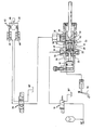
- the rapid speed change control comprises a first distributor 10, constituted in the example represented by a three-way solenoid valve with two positions, the mode of operation of which will be specified below.
- This distributor makes it possible to connect the active chamber 22 of a hydraulic cylinder 20 used for controlling the clutch (not shown) of the vehicle, either to a source of HP pressurized fluid when the control coil of this distributor is energized, either to a BP return tank when the coil is not energized (case of the position shown in the drawing).
- the control also includes a second distributor 30, constituted by a four-way and three-position solenoid valve.
- This second distributor is associated with a gearbox control mechanism, designated as a whole by the reference 40, this mechanism more precisely including two independent jacks 42 and 44, assigned respectively to the passage of increasing ratios and decreasing ratios; the structure of this mechanism is not in itself part of the invention, but it must be understood that it is designed in such a way that the pressurization of one or the other of its jacks results in a step of angular displacement in one direction or the other of an output shaft 46 which performs the desired couplings inside the box; it follows that the passage from the first to the fourth speed, for example, requires three pressurizations and successive pressurization of the corresponding cylinder.
- the central position or rest position of the distributor 30 is used to connect the two jacks 42 and 44 to the return tank BP; for this position, the gearbox (not shown in the drawing) works on the ratio which was imposed on it during a previous maneuver.
- the distributor 30 connects one of the jacks 42 and 44 to an outlet orifice 31 of the clutch control jack 20, and the other jack to the return tank BP.
- the speed change control according to the invention finally comprises two control members assigned one to the passage of increasing gears and the other to that of decreasing gears.
- These control members which are not shown in the drawing, may advantageously be constituted by push buttons mounted on the steering wheel of the vehicle, this so as to allow the driver to control with a finger and without having to release the steering wheel shifting the desired gear.
- One of these push-buttons allows, when pressed, to simultaneously supply the excitation coil of the first distributor 10 and one of the excitation coils of the second distributor 30; similarly, the second push-button controls by its depressing the supply of the excitation coil of the first distributor 10 and of the other excitation coil of the second distributor 30.
- the actuator 20 for actuating the clutch comprises a hollow piston 21 delimiting, with a fixed partition 23, an active chamber 22 which communicates with an intake orifice 24 for the fluid under pressure.
- the piston 21 places the active chamber 22 of the jack in communication with a peripheral groove 28.
- the outlet orifice 31 of the jack communicates on the other hand with a light pierced in its fixed body and extended by a longitudinal groove 29, the left end of which is normally distant from the groove 28 and is separated from it by an O-ring seal; the spacing between this end and this groove is determined in such a way that, when the piston 21 is pushed to the right under the action of the fluid under pressure, the communication between the groove and the groove is established only once accomplished a minimum value of the piston stroke corresponding to an effective disengagement of the clutch.
- the groove 29 communicates on the other hand, by means of a diametral bore 51 and an axial bore 52, with the internal cavity 26 of the piston 21; however, this communication is controlled by a unidirectional valve 50 which allows the pressurized fluid to pass only in the direction going from the outlet orifice 31 to the cavity 26 of the piston, and consequently to the active chamber 22; on examining the drawing, it will be noted that, provided that the valve 50 is open, the auxiliary passage thus formed in the piston 21 establishes a communication which is independent of the position of the piston.
- the valve 50 essentially plays a protective role against transient overpressures which may appear downstream of the jack 20 during the execution of the maneuvers.
- the jack 20 finally comprises a second actuating piston 32, mounted in series with the piston 21 on which it bears by a push rod 33 sealingly passing through the fixed partition 23; this piston 32 is actuated only in response to a voluntary operation of the clutch pedal 34, and should normally be considered only as an emergency means.
Description
La présente invention a pour objet une commande de changement de vitesse pour véhicule automobile, et elle concerne plus particulièrement une commande de ce genre comprenant un premier organe de commande pour le passage des rapports croissants et un deuxième organe de commande pour celui des rapports décroissants, un vérin à pression de fluide pour l'actionnement de l'embrayage, et un mécanisme de commande de la boîte de vitesses incluant des moyens sensibles à une pression de fluide pour le passage des rapports croissants et pour celui des rapports décroissants comme décrit, par exemple, dans le brevet US-A-3 433 101.The subject of the present invention is a speed change control for a motor vehicle, and it relates more particularly to a control of this kind comprising a first control member for shifting the increasing ratios and a second control member for that of the decreasing ratios, a fluid pressure cylinder for actuating the clutch, and a gearbox control mechanism including means sensitive to a fluid pressure for the passage of the increasing ratios and for that of the decreasing ratios as described, for example example, in patent US-A-3,433,101.
Une telle commande peut trouver notamment son application à bord des voitures de course, pour lesquelles la nécessité d'un passage rapide des vitesses, dans un sens comme dans l'autre, s'impose de toute évidence. Une telle application ne doit cependant pas être considérée comme restrictive de la portée de l'invention.Such a command can find its application in particular on board racing cars, for which the need for a rapid change of gears, in one direction as in the other, is obvious. Such an application should not however be considered as restricting the scope of the invention.
Afin d'obtenir des temps de réponse aussi courts que possible, l'invention propose que cette commande de changement de vitesse comprenne, en combinaison, un premier distributeur trois voies permettant de relier la chambre active du vérin d'embrayage soit à une source de fluide sous pression soit à un réservoir de retour selon qu'il est ou non excité, un second distributeur quatre voies associé aux moyens sensibles à une pression de fluide, eux-mêmes constitués par deux vérins indépendants, ce second distributeur permettant soit de relier en fonction de l'organe de commande actionné l'un ou l'autre desdits vérins à la source de fluide sous pression à travers la chambre active du vérin d'embrayage et l'autre vérin au réservoir de retour, soit de relier en l'absence d'excitation les deux vérins audit réservoir, ces deux distributeurs étant excités simultanément par l'un ou l'autre des organes de commande et désexcités automatiquement par un moyen de contrôle répondant à la fin d'exécution du passage du rapport désiré, et la liaison à travers la chambre active du vérin d'embrayage ne s'établissant qu'au-delà d'une valeur prédéterminée de la course de son piston qui correspond à la bonne exécution du débrayage. On est ainsi assuré que la manoeuvre de passage du rapport ne débute qu'après, et tout de suite après l'accomplissement de la manoeuvre de débrayage. La désexcitation automatique des deux distributeurs, entraînant la mise au retour des enceintes sous pression, assure d'autre part une remise à disposition rapide de la commande pour le passage éventuel d'un autre rapport.In order to obtain response times as short as possible, the invention proposes that this speed change command comprises, in combination, a first three-way distributor allowing the active chamber of the clutch cylinder to be connected to a source of pressurized fluid either to a return tank depending on whether or not it is excited, a second four-way distributor associated with means sensitive to a fluid pressure, themselves constituted by two independent jacks, this second distributor making it possible either to connect in function of the actuator actuated one or the other of said jacks to the source of pressurized fluid through the active chamber of the clutch jack and the other jack to the return tank, or to connect in the absence of excitation the two jacks to said tank, these two distributors being excited simultaneously by one or the other of the control members and de-energized automatically by a control means responding to the end of execution of the passage of the desired ratio, and the connection through the active chamber of the clutch actuator being established only beyond a predetermined value of the stroke of its piston which corresponds to the proper execution of the clutch. It is thus ensured that the gear shift maneuver does not begin until after, and immediately after the completion of the clutch release operation. The automatic de-excitation of the two distributors, causing the pressure vessels to return, on the other hand ensures rapid delivery of the command for the possible passage of another report.
Dans une forme préférentielle de réalisation de l'invention, la liaison ci-dessus évoquée à travers la chambre active du vérin d'embrayage s'établit, à travers un passage pratiqué dans le piston lui-même, entre un orifice d'admission du fluide sous pression et une lumière de sortie qui ne communique avec ledit passage que lorsque la course du piston atteint ladite valeur prédéterminée. Il doit être toutefois entendu que le même résultat pourrait être obtenu par d'autres moyens sans sortir pour autant du cadre de l'invention.In a preferred embodiment of the invention, the above connection mentioned through the active chamber of the clutch cylinder is established, through a passage made in the piston itself, between an inlet orifice of the pressurized fluid and an outlet lumen which communicates with said passage only when the piston stroke reaches said predetermined value. It should however be understood that the same result could be obtained by other means without departing from the scope of the invention.
De préférence, les organes de commande et les distributeurs sont constitués respectivement par des boutons-poussoirs et par des électrovalves, et en pareil cas le moyen de contrôle répondant à la fin d'exécution du passage du rapport désiré peut . être alors simplement constitué par un interrupteur de fin de course actionné par l'un ou l'autre des vérins de commande de la boîte de vitesses.Preferably, the control members and the distributors are constituted respectively by push-buttons and by solenoid valves, and in such a case the control means responding to the end of execution of the passage of the desired ratio can. then simply be constituted by a limit switch actuated by one or the other of the gearbox control jacks.
Les caractéristiques et avantages de l'invention ressortiront plus clairement de la lecture de la description suivante d'une forme préférentielle de réalisation, donnée à simple titre d'exemple illustratif et en se référant à l'unique figure du dessin ci-annexé qui en constitue une représentation schématique.The characteristics and advantages of the invention will emerge more clearly from reading the following description of a preferred embodiment, given simply by way of illustrative example and with reference to the single figure of the attached drawing which constitutes a schematic representation.
La commande de changement rapide de vitesse selon l'invention comprend un premier distributeur 10, constitué dans l'exemple représenté par une électrovalve à trois voies et à deux positions, dont le mode de fonctionnement sera précisé ci-après. Ce distributeur permet de relier la chambre active 22 d'un vérin hydraulique 20 utilisé pour la commande de l'embrayage (non représenté) du véhicule, soit à une source de fluide sous pression HP lorsque la bobine de commande de ce distributeur est excitée, soit à un réservoir de retour BP lorsque la bobine n'est pas excitée (cas de la position représentée sur le dessin).The rapid speed change control according to the invention comprises a
La commande comprend également un second distributeur 30, constitué celui-ci par une électrovalve à quatres voies et à trois positions. Ce second distributeur est associé à un mécanisme de commande de la boîte de vitesses, désigné dans son ensemble par le repère 40, ce mécanisme incluant plus précisément deux vérins indépendants 42 et 44, affectés respectivement au passage des rapports croissants et des rapports décroissants ; la structure de ce mécanisme ne fait pas en elle-même partie de l'invention, mais on doit comprendre qu'elle est conçue de façon telle que la mise sous pression de l'un ou de l'autre de ses vérins se traduit par un pas de déplacement angulaire dans un sens ou dans l'autre d'un arbre de sortie 46 qui réalise à l'intérieur de la boîte les couplages désirés ; il s'ensuit que le passage de la première à la quatrième vitesses, par exemple, nécessite trois mises sous pression et hors pression successives du vérin correspondant.The control also includes a
Plus précisément, la position centrale ou position de repos du distributeur 30 est utilisée pour relier les deux vérins 42 et 44 au réservoir de retour BP ; pour cette position, la boîte de vitesses (non représentée sur le dessin) travaille sur le rapport qui lui a été imposé lors d'une précédente manoeuvre. Dans l'une ou dans l'autre des deux autres positions, qui sont respectivement commandées par l'actionnement d'une bobine correspondante, le distributeur 30 relie l'un des vérins 42 et 44 à un orifice de sortie 31 du vérin 20 de commande d'embrayage, et l'autre vérin au réservoir de retour BP.More specifically, the central position or rest position of the
La commande de changement de vitesse selon l'invention comprend enfin deux organes de commande affectés l'un au passage des rapports croissants et l'autre à celui des rapports décroissants. Ces organes de commande, qui ne sont pas représentés sur le dessin, peuvent être avantageusement constitués par des boutons-poussoirs montés sur le volant du véhicule, ceci de manière à permettre au pilote de commander d'un doigt et sans avoir à lâcher le volant le passage du rapport désiré. L'un de ces boutons-poussoirs permet, lorsqu'il est enfoncé, d'alimenter simultanément la bobine d'excitation du premier distributeur 10 et l'une des bobines d'excitation du second distributeur 30 ; de manière analogue, le second bouton-poussoir commande par son enfoncement l'alimentation de la bobine d'excitation du premier distributeur 10 et de l'autre bobine d'excitation du second distributeur 30. L'enfoncement de l'un ou de l'autre de ces boutons-poussoirs a pour effet de maintenir les distributeurs dans leurs positions respectives de travail jusqu'à ce que le vérin correspondant 42 ou 44 ait parcouru une course complète, assurant ainsi la réalisation du couplage désiré. La fin de cette manoeuvre peut être avantageusement constatée par un interrupteur de fin de course 48 qui est actionné lorsque l'un ou l'autre des pistons des vérins 42 ou 44 parvient au terme de sa course. L'interrupteur 48 émet alors un signal de fin d'exécution qui provoque, par l'intermédiaire d'un dispositif de commande électronique non représenté, la mise hors tension simultanée des bobines des deux distributeurs 10 et 30.The speed change control according to the invention finally comprises two control members assigned one to the passage of increasing gears and the other to that of decreasing gears. These control members, which are not shown in the drawing, may advantageously be constituted by push buttons mounted on the steering wheel of the vehicle, this so as to allow the driver to control with a finger and without having to release the steering wheel shifting the desired gear. One of these push-buttons allows, when pressed, to simultaneously supply the excitation coil of the
Selon une variante de l'invention, il est possible d'obtenir un autre mode de fonctionnement grâce à un dispositif de commandé électronique réalisé de telle manière que l'actionnement de l'interrupteur 48 provoque la mise hors tension de la bobine du distributeur 30 tandis que la mise hors tension de la bobine du distributeur 10 qui provoque la remise en service de l'embrayage ne s'effectue que lors du relâchement du bouton-poussoir considéré, à l'instant choisi par le pilote.According to a variant of the invention, it is possible to obtain another operating mode thanks to an electronic control device produced in such a way that actuation of the
Considérant à présent plus particulièrement le vérin 20 d'actionnement de l'embrayage, on voit que celui-ci comprend un piston creux 21 délimitant avec une cloison fixe 23 une chambre active 22 qui communique avec un orifice d'admission 24 pour le fluide sous pression. Par l'intermédiaire de perçages longitudinaux 25, d'une cavité interne 26, et de perçages radiaux 27, le piston 21 met en communication la chambre active 22 du vérin avec une gorge périphérique 28. L'orifice de sortie 31 du vérin communique d'autre part avec une lumière percée dans son corps fixe et prolongée par une rainure longitudinale 29 dont l'extrémité gauche est normalement éloignée de la gorge 28 et en est séparée par un joint torique d'étanchéité ; l'espacement entre cette extrémité et cette gorge est déterminé de façon telle que, lorsque le piston 21 est repoussé vers la droite sous l'action du fluide sous pression, la communication entre la gorge et la rainure ne s'établisse qu'une fois accomplie une valeur minimale de la course du piston correspondant à un débrayage effectif de l'embrayage. La rainure 29 communique d'autre part, par l'intermédiaire d'un perçage diamétral 51 et d'un perçage axial 52, avec la cavité interne 26 du piston 21 ; toutefois, cette communication est contrôlée par un clapet unidirectionnel 50 qui ne laisse passer le fluide sous pression que dans le sens allant de l'orifice de sortie 31 à la cavité 26 du piston, et par conséquent à la chambre active 22 ; à l'examen du dessin on remarque que, sous réserve que le clapet 50 soit ouvert, le passage auxiliaire ainsi pratiqué dans le piston 21 établit une communication qui est indépendante de la position du piston. Le clapet 50 joue essentiellement un rôle de protection contre les surpressions transitoires risquant d'apparaître en aval du vérin 20 lors de l'exécution des manœuvres. Le vérin 20 comporte enfin un second piston d'actionnement 32, monté en série avec le piston 21 sur lequel il prend appui par une tige de poussée 33 traversant de façon étanche la cloison fixe 23 ; ce piston 32 n'est actionné qu'en réponse à une manoeuvre volontaire de la pédale d'embrayage 34, et doit normalement n'être considérée que comme un moyen de secours.Now considering more particularly the
Le dispositif ci-dessus décrit fonctionne de la manière suivante :
- Lorsque le pilote de la voiture désire passer à un rapport de valeur supérieure, il enfonce le bouton-poussoir correspondant, ce qui a pour effet d'exciter simultanément la bobine du
premier distributeur 10 et l'une des bobines dusecond distributeur 30, autorisant par exemple l'alimentation duvérin 42. L'àctionnement du premier distributeur 10 a pour effet d'alimenter en fluide sous pression la chambre active 22 du vérin d'embrayage 20, et la pression qui s'exerce dès cet instant sur le piston 21 provoque son déplacement vers la droite, avec pour conséquence le débrayage des plateaux de l'embrayage. Le fluide sous pression emplit simultanément la cavité interne 26 et parvient à la gorge périphérique 28, tout en maintenant d'autre part leclapet 50 appliqué sur son siège ; il en résulte que le fluide sous pression ne peut atteindre larainure 29, et par conséquent l'orifice desortie 31, que lorsque le piston aura effectué une course minimale garantissant la bonne exécution du débrayage. C'est seulement à partir de cet instant que le fluide sous pression parvient à l'entrée dusecond distributeur 30 et de là, auvérin 42. Le piston de ce dernier se déplace alors vers la droite du dessin, imprimant à l'arbre desortie 46 un pas de déplacement angulaire assurant le couplage désiré. Au terme de cette manoeuvre, l'interrupteur de fin decourse 48 se trouve actionné et désexcite simultanément les bobines des deux distributeurs. Le fluide contenu dans la chambre active duvérin 42 se trouve alors refoulé sous l'action de son ressort de rappel vers le réservoir de retour, à travers lesecond distributeur 30 dont le tiroir a repris sa position de repos représentée sur le dessin. De même, le piston 21 du vérin d'embrayage 20 revient vers sa position de repos sous l'action du ressort de rappel de l'embrayage, refoulant devant lui le fluide contenu dans la chambre active 22, lequel est retourné au réservoir BP à travers lepremier distributeur 10, lui aussi revenu à sa position de repos. Une éventuelle surpression transitoire qui apparaîtrait lors de cette manoeuvre dans la ligne reliant l'orifice desortie 31 duvérin 20 ausecond distributeur 30 provoquerait le soulèvement duclapet 50, et se trouverait ainsi éliminée de façon simple et efficace.
- When the driver of the car wishes to shift to a higher value ratio, he pushes the corresponding push button, which has the effect of simultaneously exciting the coil of the
first distributor 10 and one of the coils of thesecond distributor 30, authorizing for example the supply of thejack 42. The actuation of thefirst distributor 10 has the effect of supplying pressurized fluid to theactive chamber 22 of theclutch jack 20, and the pressure which is exerted from this moment on the piston 21 causes its displacement to the right, with the consequence of disengaging the clutch plates. The pressurized fluid simultaneously fills theinternal cavity 26 and reaches theperipheral groove 28, while on the other hand maintaining thevalve 50 applied to its seat; it follows that the pressurized fluid can only reach thegroove 29, and consequently theoutlet orifice 31, only when the piston has made a minimum stroke guaranteeing the correct execution of the declutching. It is only from this moment that the pressurized fluid reaches the inlet of thesecond distributor 30 and from there to thejack 42. The piston of the latter then moves to the right of the drawing, printing on the shaft.output 46 an angular displacement step ensuring the desired coupling. At the end of this maneuver, thelimit switch 48 is actuated and de-energizes the coils of the two distributors simultaneously. The fluid contained in the active chamber of thejack 42 is then discharged under the action of its return spring towards the return tank, through thesecond distributor 30 whose drawer has returned to its rest position shown in the drawing. Likewise, the piston 21 of theclutch cylinder 20 returns to its rest position under the action of the clutch return spring, pushing before it the fluid contained in theactive chamber 22, which is returned to the LP tank at through thefirst distributor 10, also returned to its rest position. A possible transient overpressure which would appear during this maneuver in the line connecting theoutlet orifice 31 of thejack 20 to thesecond distributor 30 would cause thevalve 50 to be raised, and would thus be eliminated in a simple and effective manner.
Il va de soi que les manoeuvres se succéderaient de façon similaire dans le cas où le pilote actionnerait l'autre organe de commande mis à sa disposition, ce qui provoquerait alors l'intervention de l'autre vérin 44 affecté au passage des rapports décroissants.It goes without saying that the maneuvers would follow one another in a similar manner in the case where the pilot actuates the other control member placed at his disposal, which would then cause the intervention of the
Grâce à l'emploi de moyens de commande à réponse rapide ainsi qu'aux moyens mis en oeuvre pour commander l'intervention du mécanisme 40 dès qu'est constatée la bonne exécution de la manoeuvre de débrayage, il est possible d'obtenir des changements de rapports en un temps extrêmement court, impossible à atteindre en commande manuelle. Par ailleurs, un succession rapide de pressions sur les boutons-poussoirs de commande permet de parcourir en un temps extrêmement réduit toute la gamme des rapports disponibles, ceci aussi bien lors des manoeuvres d'accélération que de décélération du véhicule.Thanks to the use of quick response control means as well as to the means used to control the intervention of the
En cas de défaillance de l'un ou l'autre des composants du dispositif de commande ci-dessus décrit, le conducteur conserve enfin la possibilité d'intervenir manuellement, en se servant de la pédale d'embrayage classique 34 et d'un levier de passage de vitesses.In the event of failure of one or other of the components of the control device described above, the driver finally retains the possibility of intervening manually, by using the
Claims (4)
Applications Claiming Priority (2)
| Application Number | Priority Date | Filing Date | Title |
|---|---|---|---|
| IT1952079 | 1979-01-23 | ||
| IT19520/79A IT1110714B (en) | 1979-01-23 | 1979-01-23 | SPEED CHANGE CONTROL FOR AUTOMOBILE VEHICLE |
Publications (2)
| Publication Number | Publication Date |
|---|---|
| EP0014143A1 EP0014143A1 (en) | 1980-08-06 |
| EP0014143B1 true EP0014143B1 (en) | 1982-09-01 |
Family
ID=11158721
Family Applications (1)
| Application Number | Title | Priority Date | Filing Date |
|---|---|---|---|
| EP80400087A Expired EP0014143B1 (en) | 1979-01-23 | 1980-01-21 | Speed change control for a motor vehicle |
Country Status (3)
| Country | Link |
|---|---|
| EP (1) | EP0014143B1 (en) |
| DE (1) | DE3060784D1 (en) |
| IT (1) | IT1110714B (en) |
Cited By (2)
| Publication number | Priority date | Publication date | Assignee | Title |
|---|---|---|---|---|
| DE3709166C1 (en) * | 1987-03-20 | 1988-09-22 | Knorr Bremse Ag | Hydropneumatic clutch amplifier for motor vehicles |
| DE102014102880A1 (en) * | 2014-03-05 | 2015-09-10 | Knorr-Bremse Systeme für Nutzfahrzeuge GmbH | Coupling booster with special dynamic sealant located in the area of the piston rod |
Families Citing this family (3)
| Publication number | Priority date | Publication date | Assignee | Title |
|---|---|---|---|---|
| DE3217662C2 (en) * | 1982-05-11 | 1985-11-07 | Emil Weber Fabrik für Ölhydraulik GmbH & Co, 7129 Güglingen | Hydraulic actuator for the clutch of motor vehicles |
| DE3370461D1 (en) * | 1983-06-23 | 1987-04-30 | Bendix Italia | Hydraulic actuating means of a control device, in particular of a gear changing device |
| GB201509217D0 (en) * | 2015-05-28 | 2015-07-15 | Raicam Clutch Ltd | Vehicle driveline control systems |
Family Cites Families (5)
| Publication number | Priority date | Publication date | Assignee | Title |
|---|---|---|---|---|
| DE1224620B (en) * | 1954-10-28 | 1966-09-08 | Daimler Benz Ag | Gear shift device for motor vehicles, especially for racing and sports cars |
| DE1163164B (en) * | 1955-02-15 | 1964-02-13 | Citroen Sa | Hydraulic control device for changing gears in speed change transmissions of motor vehicles |
| DE1505535C3 (en) * | 1966-01-27 | 1978-09-21 | Robert Bosch Gmbh, 7000 Stuttgart | Automatic electrical control device for a motor vehicle gear change transmission |
| DE1750114C3 (en) * | 1968-03-30 | 1975-01-30 | Ardie-Werk Gmbh, 8500 Nuernberg | Device for the semi or fully automatic switching of gear change transmissions for motor vehicles |
| FR2078997A5 (en) * | 1970-02-28 | 1971-11-05 | Cav Ltd |
-
1979
- 1979-01-23 IT IT19520/79A patent/IT1110714B/en active
-
1980
- 1980-01-21 DE DE8080400087T patent/DE3060784D1/en not_active Expired
- 1980-01-21 EP EP80400087A patent/EP0014143B1/en not_active Expired
Cited By (4)
| Publication number | Priority date | Publication date | Assignee | Title |
|---|---|---|---|---|
| DE3709166C1 (en) * | 1987-03-20 | 1988-09-22 | Knorr Bremse Ag | Hydropneumatic clutch amplifier for motor vehicles |
| DE102014102880A1 (en) * | 2014-03-05 | 2015-09-10 | Knorr-Bremse Systeme für Nutzfahrzeuge GmbH | Coupling booster with special dynamic sealant located in the area of the piston rod |
| DE102014102880B4 (en) * | 2014-03-05 | 2015-10-08 | Knorr-Bremse Systeme für Nutzfahrzeuge GmbH | Coupling booster with special dynamic sealant located in the area of the piston rod |
| EP3114365B1 (en) * | 2014-03-05 | 2020-05-20 | KNORR-BREMSE Systeme für Nutzfahrzeuge GmbH | Clutch servo with special dynamic sealing means provided in the region of the piston rod |
Also Published As
| Publication number | Publication date |
|---|---|
| EP0014143A1 (en) | 1980-08-06 |
| DE3060784D1 (en) | 1982-10-28 |
| IT1110714B (en) | 1986-01-06 |
| IT7919520A0 (en) | 1979-01-23 |
Similar Documents
| Publication | Publication Date | Title |
|---|---|---|
| FR2816894A1 (en) | HYDRAULIC ACTUATION SYSTEM | |
| EP1042148B1 (en) | Master cylinder and travel simulator arrangement for a motor vehicle electro-hydraulic brake installation | |
| FR2573708A1 (en) | STARTING ASSISTANCE DEVICE FOR MOTOR VEHICLE | |
| FR2570036A1 (en) | EMERGENCY DEVICE FOR AN ELECTRONIC CONTROL SYSTEM FOR AUTOMATIC TRANSMISSION | |
| FR2820694A1 (en) | HYDRAULIC ACTUATION SYSTEM | |
| FR2569381A1 (en) | CIRCUIT ARRANGEMENT FOR CONTROLLING A CLUTCH OF A MOTOR VEHICLE | |
| FR2528780A1 (en) | ||
| EP2437963B1 (en) | Brake system having a master cylinder that is decoupled from the brake pedal and hydraulic brake booster | |
| FR2818944A1 (en) | HYDRAULIC BRAKING SYSTEM FOR VEHICLE COMPRISING AN ACTIVE SIMULATOR | |
| FR2880854A1 (en) | BRAKE VALVE DEVICE | |
| EP0014143B1 (en) | Speed change control for a motor vehicle | |
| FR2576261A1 (en) | BRAKE PRESSURE GENERATOR FOR MOTOR VEHICLE | |
| FR2878804A1 (en) | VALVE ASSEMBLY FOR ANTI-SKATING BRAKES OF AN AIRCRAFT | |
| FR2798442A1 (en) | AUTOMATIC TRANSMISSION SYSTEM | |
| FR2678869A1 (en) | UTILITY VEHICLE WITH FOUR WHEELS. | |
| FR2500391A1 (en) | ANTI-SLAVE FACILITIES FOR VEHICLE BRAKES | |
| FR2642016A1 (en) | CHANGE CONTROL FOR MOTOR VEHICLES, IN PARTICULAR AGRICULTURAL TRACTORS | |
| FR2726514A1 (en) | EMERGENCY CLUTCH / RELEASE DEVICE FOR UTILITY VEHICLES | |
| FR2828662A1 (en) | HYDRAULIC CONTROL SYSTEMS | |
| EP0809048A1 (en) | Gear shift device for automotive vehicles with shifting assistance to certain ratios | |
| FR2747171A1 (en) | ELECTROHYDRAULIC ACTUATOR FOR THE CONTROL OF A VEHICLE GEARBOX OF THE INLET BARREL TYPE | |
| FR2556291A1 (en) | Remote control installation for a gearbox, of the mechanical type | |
| FR2804194A1 (en) | REPORT LOCKING MECHANISM | |
| FR2805876A1 (en) | HYDRAULIC MANEUVER SYSTEM | |
| EP1564098B1 (en) | Brake system including a master cylinder and a double vacuum booster |
Legal Events
| Date | Code | Title | Description |
|---|---|---|---|
| PUAI | Public reference made under article 153(3) epc to a published international application that has entered the european phase |
Free format text: ORIGINAL CODE: 0009012 |
|
| AK | Designated contracting states |
Designated state(s): CH DE FR GB NL SE |
|
| 17P | Request for examination filed |
Effective date: 19801124 |
|
| GRAA | (expected) grant |
Free format text: ORIGINAL CODE: 0009210 |
|
| AK | Designated contracting states |
Designated state(s): CH DE FR GB NL SE |
|
| REF | Corresponds to: |
Ref document number: 3060784 Country of ref document: DE Date of ref document: 19821028 |
|
| PGFP | Annual fee paid to national office [announced via postgrant information from national office to epo] |
Ref country code: CH Payment date: 19950113 Year of fee payment: 16 |
|
| PGFP | Annual fee paid to national office [announced via postgrant information from national office to epo] |
Ref country code: SE Payment date: 19950118 Year of fee payment: 16 |
|
| EAL | Se: european patent in force in sweden |
Ref document number: 80400087.5 |
|
| PGFP | Annual fee paid to national office [announced via postgrant information from national office to epo] |
Ref country code: NL Payment date: 19950131 Year of fee payment: 16 |
|
| PG25 | Lapsed in a contracting state [announced via postgrant information from national office to epo] |
Ref country code: SE Effective date: 19960122 |
|
| PG25 | Lapsed in a contracting state [announced via postgrant information from national office to epo] |
Ref country code: CH Effective date: 19960131 |
|
| PG25 | Lapsed in a contracting state [announced via postgrant information from national office to epo] |
Ref country code: NL Effective date: 19960801 |
|
| REG | Reference to a national code |
Ref country code: CH Ref legal event code: PL |
|
| NLV4 | Nl: lapsed or anulled due to non-payment of the annual fee |
Effective date: 19960801 |
|
| EUG | Se: european patent has lapsed |
Ref document number: 80400087.5 |
|
| PGFP | Annual fee paid to national office [announced via postgrant information from national office to epo] |
Ref country code: GB Payment date: 19990113 Year of fee payment: 20 |
|
| PGFP | Annual fee paid to national office [announced via postgrant information from national office to epo] |
Ref country code: FR Payment date: 19990114 Year of fee payment: 20 |
|
| PGFP | Annual fee paid to national office [announced via postgrant information from national office to epo] |
Ref country code: DE Payment date: 19990330 Year of fee payment: 20 |
|
| PG25 | Lapsed in a contracting state [announced via postgrant information from national office to epo] |
Ref country code: GB Free format text: LAPSE BECAUSE OF EXPIRATION OF PROTECTION Effective date: 20000120 |
|
| REG | Reference to a national code |
Ref country code: GB Ref legal event code: PE20 Effective date: 20000120 |
|
| PLBE | No opposition filed within time limit |
Free format text: ORIGINAL CODE: 0009261 |
|
| STAA | Information on the status of an ep patent application or granted ep patent |
Free format text: STATUS: NO OPPOSITION FILED WITHIN TIME LIMIT |