EP0013733A1 - Variable transporting and assembling system - Google Patents
Variable transporting and assembling system Download PDFInfo
- Publication number
- EP0013733A1 EP0013733A1 EP79105114A EP79105114A EP0013733A1 EP 0013733 A1 EP0013733 A1 EP 0013733A1 EP 79105114 A EP79105114 A EP 79105114A EP 79105114 A EP79105114 A EP 79105114A EP 0013733 A1 EP0013733 A1 EP 0013733A1
- Authority
- EP
- European Patent Office
- Prior art keywords
- transport
- stations
- assembly
- station
- assembly system
- Prior art date
- Legal status (The legal status is an assumption and is not a legal conclusion. Google has not performed a legal analysis and makes no representation as to the accuracy of the status listed.)
- Granted
Links
- 239000000872 buffer Substances 0.000 claims description 6
- 230000008878 coupling Effects 0.000 claims description 2
- 238000010168 coupling process Methods 0.000 claims description 2
- 238000005859 coupling reaction Methods 0.000 claims description 2
- 238000009420 retrofitting Methods 0.000 claims 1
- 230000008901 benefit Effects 0.000 description 6
- 238000003754 machining Methods 0.000 description 4
- 230000015572 biosynthetic process Effects 0.000 description 2
- 230000000712 assembly Effects 0.000 description 1
- 238000000429 assembly Methods 0.000 description 1
- 230000003139 buffering effect Effects 0.000 description 1
- 239000000969 carrier Substances 0.000 description 1
- 238000011161 development Methods 0.000 description 1
- 230000018109 developmental process Effects 0.000 description 1
- 238000010586 diagram Methods 0.000 description 1
- 238000000034 method Methods 0.000 description 1
- 230000008569 process Effects 0.000 description 1
- 230000009467 reduction Effects 0.000 description 1
- 230000033764 rhythmic process Effects 0.000 description 1
- 238000011144 upstream manufacturing Methods 0.000 description 1
Images
Classifications
-
- B—PERFORMING OPERATIONS; TRANSPORTING
- B65—CONVEYING; PACKING; STORING; HANDLING THIN OR FILAMENTARY MATERIAL
- B65G—TRANSPORT OR STORAGE DEVICES, e.g. CONVEYORS FOR LOADING OR TIPPING, SHOP CONVEYOR SYSTEMS OR PNEUMATIC TUBE CONVEYORS
- B65G37/00—Combinations of mechanical conveyors of the same kind, or of different kinds, of interest apart from their application in particular machines or use in particular manufacturing processes
- B65G37/02—Flow-sheets for conveyor combinations in warehouses, magazines or workshops
-
- B—PERFORMING OPERATIONS; TRANSPORTING
- B23—MACHINE TOOLS; METAL-WORKING NOT OTHERWISE PROVIDED FOR
- B23P—METAL-WORKING NOT OTHERWISE PROVIDED FOR; COMBINED OPERATIONS; UNIVERSAL MACHINE TOOLS
- B23P21/00—Machines for assembling a multiplicity of different parts to compose units, with or without preceding or subsequent working of such parts, e.g. with programme control
- B23P21/004—Machines for assembling a multiplicity of different parts to compose units, with or without preceding or subsequent working of such parts, e.g. with programme control the units passing two or more work-stations whilst being composed
-
- B—PERFORMING OPERATIONS; TRANSPORTING
- B23—MACHINE TOOLS; METAL-WORKING NOT OTHERWISE PROVIDED FOR
- B23Q—DETAILS, COMPONENTS, OR ACCESSORIES FOR MACHINE TOOLS, e.g. ARRANGEMENTS FOR COPYING OR CONTROLLING; MACHINE TOOLS IN GENERAL CHARACTERISED BY THE CONSTRUCTION OF PARTICULAR DETAILS OR COMPONENTS; COMBINATIONS OR ASSOCIATIONS OF METAL-WORKING MACHINES, NOT DIRECTED TO A PARTICULAR RESULT
- B23Q7/00—Arrangements for handling work specially combined with or arranged in, or specially adapted for use in connection with, machine tools, e.g. for conveying, loading, positioning, discharging, sorting
- B23Q7/14—Arrangements for handling work specially combined with or arranged in, or specially adapted for use in connection with, machine tools, e.g. for conveying, loading, positioning, discharging, sorting co-ordinated in production lines
Definitions
- the invention is based on a transport and assembly system according to the preamble of the main claim.
- a workpiece with a certain delivery condition passes through several workplaces arranged one behind the other and is gradually perfected.
- Each workstation relies on the delivery of the workpiece through the upstream workstation, so all workstations on the same assembly line are tied to a certain cycle time in their work rhythm.
- the workplace concerned In the event of staff shortages, the workplace concerned must be filled by a so-called jumper so that the Workpiece flow is not interrupted.
- a certain independence from neighboring workplaces was first created by local buffering at each workstation.
- the arrangement according to the invention with the characterizing features of the main claim has the advantage, in contrast, that a transport and assembly system was created which copes with different types of work with different assembly sequences without requiring more space in the system.
- the system is particularly suitable for assembly tasks with a large Typensprektrum with different model variants, as well as the arrangement of several S D ezial warmth is possible.
- the transport and assembly system within the size range is product-independent and can be reused as desired. Due to the interchangeability of the individual different or similar stations, the transport and assembly system is largely type-flexible with regard to the processing steps involved.
- Another advantage is that it is possible to set up and try out new stations outside, as well as a reduction in set-up times that can be achieved as a result, since the workstations can be converted before they are used in the transport and assembly system. This results in a higher degree of utilization. Finally, as a further advantage it should be mentioned that additional spaces can also be integrated retrospectively when planning vacancies.
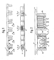
- FIG. 1 shows a schematic diagram of the transport and assembly system according to the invention with stations not retracted
- FIG. 2 shows a schematic Representation of the system with stations in their working position.
- the transport and assembly system shown in FIG. 1 is constructed in a modular system, a uniform grid system being provided for the exchangeable stations such as workstations 5, buffers 6 and automatic stations 7.
- the cross conveyor 3a and 3b are assigned to the assembly line 1 shown in FIG. 1, the cross conveyors serving to transport or remove the workpieces to the individual stations 2a, 2b, 2c etc.
- the individual stations 2a, b, c can be constructed very differently. Possible stations are, for example, machining stations 5, swap buffers 6, automatic machining stations 7, and further machining or treatment stations for workpieces. It can beiliebig other station types, such as N ietvorraumen, screwing, etc. are used, as far as the external dimensions and the connections match.
- the individual stations are stored in a depot 8 or prepared for use.
- the stations in the grid system of the transport and assembly system can occupy any positions (2a, 2b, 2c, etc.),
- FIG. 2 shows the schematic representation of the transport and assembly system with a processing station 5 and an exchangeable buffer 6 in the working position.
- the individual stations are equipped with their own conveyor belt, a roller conveyor or slide rail 4, as a result of which the connection of the cross conveyors 3a, 3b parallel to the conveyor belt 1 and thus the deflected workpiece transport is accomplished.
- the stations 2a, 2b, 2c ... are inserted into the grid system between the cross conveyors 3a, 3b and locked or fixed there.
- Each station is equipped with the control necessary for the work process, with a quick coupling system for supply connections such as the immediate operational readiness of the station.
- a depot 8 with ready-to-use, mobile exchange stations is assigned to the transport and assembly system, which enables the transport and assembly system to be supplemented and / or converted quickly.
- the device according to the invention can be used with all belt systems.
Landscapes
- Engineering & Computer Science (AREA)
- Mechanical Engineering (AREA)
- Automatic Assembly (AREA)
- Multi-Process Working Machines And Systems (AREA)
- General Factory Administration (AREA)
- Automobile Manufacture Line, Endless Track Vehicle, Trailer (AREA)
- Control Of Conveyors (AREA)
- Intermediate Stations On Conveyors (AREA)
- Structure Of Belt Conveyors (AREA)
Abstract
Description
Die Erfindung geht aus von einem Transport- und Montagesystem nach der Gattung des Hauptanspruchs. Bei der üblichen Fließbandarbeit durchläuft ein Werkstück mit bestimmten Anlieferungszustand mehrere hintereinander angeordnete Arbeitsplätze und wird dabei schrittweise vervollkommnet. Dabei ist jeder Arbeitsplatz auf die Zulieferung des Werkstückes durch den jeweils vorgeschalteten Arbeitsplatz angewiesen, sämtliche Arbeitsplätze ein und desselben Fließbandes sind also in ihrem Arbeitsrhytmus an eine bestimmte Taktzeit gebunden. Bei Personalausfall muß der betroffene Arbeitsplatz durch einen sogenannten Springer besetzt werden, damit der Werkstückfluß nicht unterbrochen wird. Um diesen Nachteil zu beheben, wurde zunächst durch örtliche Pufferbildung an jedem Arbeitsplatz eine gewisse Unabhängigkeit von benachbarten Arbeitsplätzen geschaffen. Im Zuge der zunehmenden Humanisierung des Arbeitsplatzes wurde sodann ein Transportsystem-zur Verkettung von Arbeitsplätzen geschaffen; was die Zuführung und den Abtransport von Werkstücken mit Pufferbildung vor und nach den Arbeitsplätzen gestattet, wobei an den einzelnen Arbeitsplätzen ohne Taktbildung gearbeitet werden kann (P 25 15 829.6). Dieses System hat jedoch den Nachteil, daß es, sofern es einmal aufgebaut ist, bezüglich einer variablen Werkstückbearbeitung und -behandlung nicht sehr flexibel ist.The invention is based on a transport and assembly system according to the preamble of the main claim. In the usual assembly line work, a workpiece with a certain delivery condition passes through several workplaces arranged one behind the other and is gradually perfected. Each workstation relies on the delivery of the workpiece through the upstream workstation, so all workstations on the same assembly line are tied to a certain cycle time in their work rhythm. In the event of staff shortages, the workplace concerned must be filled by a so-called jumper so that the Workpiece flow is not interrupted. In order to remedy this disadvantage, a certain independence from neighboring workplaces was first created by local buffering at each workstation. In the course of the increasing humanization of the workplace, a transport system for chaining jobs was created; which allows the feeding and removal of workpieces with buffer formation before and after the workplaces, whereby work can be done on the individual workplaces without cycle formation (P 25 15 829.6). However, this system has the disadvantage that, once it has been set up, it is not very flexible with regard to variable workpiece machining and treatment.
Die erfindungsgemäße Anordnung mit den kennzeichnenden Merkmalen des Hauptanspruchs hat demgegenüber den Vorteil, daß'ein Transport- und Montagesystem geschaffen wurde, das typbezogen abweichende Arbeitsgänge mit unterschiedlichen Montagefolgen ohne höheren Platzbedarf im System bewältigt. Durch die schnelle Umrüstbarkeit, eignet sich das System besonders für Montageaufgaben bei großem Typensprektrum mit unterschiedlichen Typenvarianten, da auch die Anordnung mehrer SDezialplätze möglich ist. Hierdurch wird das Transport- und Montagesystem im Rahmen der Größenstufe erzeugnisunabhängig und beliebig wiederverwendbar. Durch die beliebige Austauschbarkeit der einzelnen verschiedenartigen oder gleichartigen Stationen ist das Transport- und Montagesystem bezüglich den anfallenden Bearbeitungsgängen weitgehend typenflexibel.The arrangement according to the invention with the characterizing features of the main claim has the advantage, in contrast, that a transport and assembly system was created which copes with different types of work with different assembly sequences without requiring more space in the system. Through the quick set, the system is particularly suitable for assembly tasks with a large Typensprektrum with different model variants, as well as the arrangement of several S D ezialplätze is possible. As a result, the transport and assembly system within the size range is product-independent and can be reused as desired. Due to the interchangeability of the individual different or similar stations, the transport and assembly system is largely type-flexible with regard to the processing steps involved.
Es können z.B. im Grenzfall alle Plätze des Erzeugnisses A ausgetauscht werden und durch Arbeitsplätze mit Erzeugnis B belegt werden. Dies gilt insbesondere auch deshalb, da die Reihenfolge der Stationen wie z.B. der Arbeitsplätze, Puffer- und Automatikstationen beliebig kombinierbar sind. Das System weist als weiteren Vorteil eine geringere Gesamtlänge auf, da nicht benötigte Plätze im Depot verbleiben können. Hierdurch ergibt sich eine kürzere Werkstück-Durchlaufzeit, und somit wiederum weniger Werkstückträger und weniger Platzbedarf. Das System ist jedoch problemlos erweiterungsfähig. Eine spätere Automatisierbarkeit von Arbeitsgängen ist auf vorteilhafte Weise einfach durchführbar, da die Montagefolge beliebig kombinierbar ist. Das Transport- und Montagesystem ist insbesondere geeignet für Werkstückträger-Bandmontagen, sowie für Einzel-und Parallelplätze. Als weiterer Vorteil ist es anzusehen, daß der Aufbau und die Ausprobe neuer Stationen außerhalb möglich ist, sowie auch eine dadurch erreichbare Reduzierung der Rüstzeiten, da die Arbeitsplätze schon vor dem Einsetzen in das Transport- und Montagesystem umgerüstet werden können. Hierdurch ergibt sich ein höherer Nutzungsgrad. Als weiterer Vorteil sei schließlich erwähnt, daß bei-Einplanung von Leerstellen auch nachträglich zusätzliche Arbeitsgänge integrierbar sind.In the borderline case, for example, all places of product A can be exchanged and occupied with product B by workplaces. This is especially true because the order of the stations such as the work spaces, buffer and automatic stations can be combined as required. As a further advantage, the system has a shorter overall length, since unused spaces can remain in the depot. This results in a shorter workpiece throughput time, and in turn less workpiece carriers and less space. However, the system is easily expandable. A later automation of work steps can be carried out advantageously in an advantageous manner, since the assembly sequence can be combined as desired. The transport and assembly system is particularly suitable for workpiece carrier belt assemblies, as well as for single and parallel places. Another advantage is that it is possible to set up and try out new stations outside, as well as a reduction in set-up times that can be achieved as a result, since the workstations can be converted before they are used in the transport and assembly system. This results in a higher degree of utilization. Finally, as a further advantage it should be mentioned that additional spaces can also be integrated retrospectively when planning vacancies.
Durch die in den Unteransprüchen aufgeführten Maßnahmen sind vorteilhafte Weiterbildungen und Verbesserungen des im Hauptanspruch angegebenen Systems möglich. Auf die weiteren Vorteile wird in der nachfolgenden Beschreibung näher eingegangen.Advantageous further developments and improvements of the system specified in the main claim are possible through the measures listed in the subclaims. The further advantages are discussed in more detail in the description below.
Ein Ausführungsbeispiel der Erfindung ist in der Zeichnung dargestellt und in der nachfolgenden Beschreibung näher erläutet. Es zeigen Fiz. 1 eine Prinzipdarstellung des erfindungsgemäßen Transport- und Montagesystems mit nicht eingefahrenen Stationen, Fig. 2 eine schematische Darstellung des Systems mit Stationen in ihrer Arbeitsstellung.An embodiment of the invention is shown in the drawing and explained in more detail in the following description. It shows Fiz. 1 shows a schematic diagram of the transport and assembly system according to the invention with stations not retracted, FIG. 2 shows a schematic Representation of the system with stations in their working position.
Das in Fig. 1 dargestellte Transport- und Montagesystem ist im Baukastensystem aufgebaut, wobei ein einheitliches Rastersystem für die auswechselbaren Stationen wie z.B. Arbeitsplätze 5, Puffer 6 und Automatikstationen 7 vorgesehen ist. Dem in Fig. 1 dargestellten Fließband 1 sind Querförderer 3a und 3b zugeordnet, wobei die Querförderer der Transportzu- bzw. abfuhr der Werkstücke zu den einzelnen Stationen 2a , 2b, 2c usw. dienen. Die einzelnen Stationen 2a, b, c können sehr unterschiedlich aufgebaut sein. Mögliche Stationen sind z.B. Bearbeitungsplätze 5, Wechselpuffer 6, automatische Bearbeituhgsstationen 7, sowie weitere Bearbeitungs- oder Behandlungsstationen für Werkstücke. Es können beiliebig weitere Stationsarten, wie z.B. Nietvorrichtungen, Schraubvorrichtungen usw. Verwendung finden, soweit die Außenmaße und die Anschlüsse zueinander passen. Die einzelnen Stationen werden in einem Depot 8 gelagert bzw. für den Einsatz vorbereitet. Dabei können die Stationen im Rastersystem des Transport-und Montagesystems beliebige Plätze (2a, 2b, 2c usw.) einnehmen,The transport and assembly system shown in FIG. 1 is constructed in a modular system, a uniform grid system being provided for the exchangeable stations such as
Fig. 2 zeigt die schematische Darstellung des Transport-und Montagesystems mit einer Bearbeitungsstation 5 und einem Wechselpuffer 6 in Arbeitsstellung. Die einzelnen Stationen sind mit einem eigenen Transportband, einer Rollenbahn oder Gleitschiene 4 ausgerüstet, wodurch die zum Fließband 1 parallele Verbindung der Querförderer 3a, 3b und somit der umgelenkte Werkstücktransport bewerkstelligt wird. Durch die Ausbildung der Stationen als variable, auswechselbare Station können diese beliebig untereinander ausgetauscht werden. Die Stationen 2a, 2b, 2c ... werden dabei in das Rastersystem zwischen die Querförderer 3a, 3b eingeschoben und dort arretiert bzw. fixiert. Jede Station ist dabei mit der für den Arbeitsgang notwendigen Steuerung ausgerüstet, wobei ein Schnellkupplungssystem für Versorgungsanschlüsse wie z.B. die sofortige Einsatzbereitschaft der Station gewährleistet. Dem Transport- und Montagesystem ist ein Depot 8 mit einsatzbereiten, fahrbaren Auswechselstationen zugeordnet, wodurch eine schnelle Ergänzung und/oder Umrüstung des Transport- und Montagesystems ermöglicht wird. Die erfindungsgemäße Einrichtung ist bei allen Bandsystemen anwendbar.2 shows the schematic representation of the transport and assembly system with a
Claims (7)
Priority Applications (1)
| Application Number | Priority Date | Filing Date | Title |
|---|---|---|---|
| AT79105114T ATE378T1 (en) | 1979-01-10 | 1979-12-12 | VARIABLE TRANSPORT AND ASSEMBLY SYSTEM. |
Applications Claiming Priority (2)
| Application Number | Priority Date | Filing Date | Title |
|---|---|---|---|
| DE2900650 | 1979-01-10 | ||
| DE19792900650 DE2900650A1 (en) | 1979-01-10 | 1979-01-10 | VARIABLE TRANSPORT AND ASSEMBLY SYSTEM |
Publications (2)
| Publication Number | Publication Date |
|---|---|
| EP0013733A1 true EP0013733A1 (en) | 1980-08-06 |
| EP0013733B1 EP0013733B1 (en) | 1981-11-11 |
Family
ID=6060241
Family Applications (1)
| Application Number | Title | Priority Date | Filing Date |
|---|---|---|---|
| EP79105114A Expired EP0013733B1 (en) | 1979-01-10 | 1979-12-12 | Variable transporting and assembling system |
Country Status (4)
| Country | Link |
|---|---|
| EP (1) | EP0013733B1 (en) |
| JP (1) | JPS5596258A (en) |
| AT (1) | ATE378T1 (en) |
| DE (2) | DE2900650A1 (en) |
Cited By (10)
| Publication number | Priority date | Publication date | Assignee | Title |
|---|---|---|---|---|
| EP0056063A1 (en) * | 1981-01-08 | 1982-07-21 | Johann A. Krause Maschinenfabrik | Plant for transferring workpieces subject to operating stations |
| FR2541974A1 (en) * | 1983-03-11 | 1984-09-07 | Prodel Maurice | Module for circulating workpiece-carrying pallets for a flexible machining or assembly workshop and flexible workshop comprising such modules |
| US4519491A (en) * | 1980-10-14 | 1985-05-28 | Maurice Prodel | Apparatus for the assembly and/or machining of circulating and immobilizable parts carried by pallets |
| EP0201262A1 (en) * | 1985-04-30 | 1986-11-12 | International Business Machines Corporation | Automated product assembly system |
| WO1994005571A1 (en) * | 1992-09-01 | 1994-03-17 | Robert Bosch Gmbh | Flexible conveyor system |
| FR2700525A1 (en) * | 1993-01-15 | 1994-07-22 | Innovations Atel Const | Conveyor system e.g. for transporting articles in store |
| WO1996024545A1 (en) * | 1995-02-10 | 1996-08-15 | Robert Bosch Gmbh | Modular continuous production facility |
| FR2892040A1 (en) * | 2005-10-18 | 2007-04-20 | Ys Etudes Et Ind Sarl | Automated complex mechanical part fabricating step performing module, has automaton receiving mechanical part`s fabricating step starting order from central automaton and sending information of end of step to central automaton |
| WO2009100947A2 (en) * | 2008-02-15 | 2009-08-20 | Fachhochschule Aschaffenburg | Modular manufacturing plant |
| WO2016206895A3 (en) * | 2015-06-26 | 2017-02-16 | Zf Friedrichshafen Ag | Method and device for reducing the energy demand of a machine tool and machine tool system |
Families Citing this family (3)
| Publication number | Priority date | Publication date | Assignee | Title |
|---|---|---|---|---|
| JPH04111347U (en) * | 1991-03-12 | 1992-09-28 | 恒真産業株式会社 | Simple heating element for chemical liquids |
| DE4422416C1 (en) * | 1994-06-29 | 1996-01-11 | Magnus Dipl Ing Gruener | Machining center |
| JP5191789B2 (en) * | 2008-04-28 | 2013-05-08 | オリンパス株式会社 | Production equipment and production system |
Citations (4)
| Publication number | Priority date | Publication date | Assignee | Title |
|---|---|---|---|---|
| DE2521787A1 (en) * | 1974-05-18 | 1975-11-27 | Lucas Electrical Co Ltd | ASSEMBLY TAPE SYSTEM |
| DE2515829A1 (en) * | 1975-04-11 | 1976-10-21 | Bosch Gmbh Robert | TRANSPORT SYSTEM FOR LINKING PARALLEL WORKPLACES |
| DE2657795A1 (en) * | 1976-01-16 | 1977-07-21 | Lanco Ag | CONVEYOR BELT SYSTEM FOR PERFORMING WORK SUCCESSIVE ON A SERIES OF SIMILAR APPARATUS |
| DE2501054B2 (en) * | 1974-02-15 | 1977-12-15 | PROCEDURE FOR AUTOMATED EXECUTION OF CHEMICAL AND / OR PHYSICAL ANALYZES AND EQUIPMENT FOR CARRYING OUT THE PROCEDURE |
Family Cites Families (1)
| Publication number | Priority date | Publication date | Assignee | Title |
|---|---|---|---|---|
| JPS5049778A (en) * | 1973-09-04 | 1975-05-02 |
-
1979
- 1979-01-10 DE DE19792900650 patent/DE2900650A1/en not_active Withdrawn
- 1979-12-12 AT AT79105114T patent/ATE378T1/en active
- 1979-12-12 EP EP79105114A patent/EP0013733B1/en not_active Expired
- 1979-12-12 DE DE7979105114T patent/DE2961332D1/en not_active Expired
-
1980
- 1980-01-10 JP JP95080A patent/JPS5596258A/en active Granted
Patent Citations (5)
| Publication number | Priority date | Publication date | Assignee | Title |
|---|---|---|---|---|
| DE2501054B2 (en) * | 1974-02-15 | 1977-12-15 | PROCEDURE FOR AUTOMATED EXECUTION OF CHEMICAL AND / OR PHYSICAL ANALYZES AND EQUIPMENT FOR CARRYING OUT THE PROCEDURE | |
| DE2521787A1 (en) * | 1974-05-18 | 1975-11-27 | Lucas Electrical Co Ltd | ASSEMBLY TAPE SYSTEM |
| DE2515829A1 (en) * | 1975-04-11 | 1976-10-21 | Bosch Gmbh Robert | TRANSPORT SYSTEM FOR LINKING PARALLEL WORKPLACES |
| DE2657795A1 (en) * | 1976-01-16 | 1977-07-21 | Lanco Ag | CONVEYOR BELT SYSTEM FOR PERFORMING WORK SUCCESSIVE ON A SERIES OF SIMILAR APPARATUS |
| CH596062A5 (en) * | 1976-01-16 | 1978-02-28 | Lanco Ag |
Non-Patent Citations (3)
| Title |
|---|
| MASCHINENMARKT, Band 81, Nr. 51, 1975 Wurzburg "Montagelinie mit taktunabhangigen Arbeitsplatzen" Seiten 943 und 944. * |
| WERKSTATTSTECHNIK, Band 60, Nr. 8, 1970 Berlin C.M. DOLEZALEK et al. "Flexible Fertigungssysteme" Seite 449 bis 451. * |
| WERKSTATTSTECHNIK, Band 67, Nr. 4, 1977 Berlin F. KREMPEL "Flexible Montagesysteme" Seiten 223 bis 227. * |
Cited By (13)
| Publication number | Priority date | Publication date | Assignee | Title |
|---|---|---|---|---|
| US4519491A (en) * | 1980-10-14 | 1985-05-28 | Maurice Prodel | Apparatus for the assembly and/or machining of circulating and immobilizable parts carried by pallets |
| US4787496A (en) * | 1980-10-14 | 1988-11-29 | Maurice Prodel | Apparatus for the assembly and/or machining of circulating and immobilizable parts carried by pallets |
| EP0056063A1 (en) * | 1981-01-08 | 1982-07-21 | Johann A. Krause Maschinenfabrik | Plant for transferring workpieces subject to operating stations |
| FR2541974A1 (en) * | 1983-03-11 | 1984-09-07 | Prodel Maurice | Module for circulating workpiece-carrying pallets for a flexible machining or assembly workshop and flexible workshop comprising such modules |
| EP0201262A1 (en) * | 1985-04-30 | 1986-11-12 | International Business Machines Corporation | Automated product assembly system |
| WO1994005571A1 (en) * | 1992-09-01 | 1994-03-17 | Robert Bosch Gmbh | Flexible conveyor system |
| FR2700525A1 (en) * | 1993-01-15 | 1994-07-22 | Innovations Atel Const | Conveyor system e.g. for transporting articles in store |
| WO1996024545A1 (en) * | 1995-02-10 | 1996-08-15 | Robert Bosch Gmbh | Modular continuous production facility |
| US5884746A (en) * | 1995-02-10 | 1999-03-23 | Robert Bosch Gmbh | Modular assembly line system |
| FR2892040A1 (en) * | 2005-10-18 | 2007-04-20 | Ys Etudes Et Ind Sarl | Automated complex mechanical part fabricating step performing module, has automaton receiving mechanical part`s fabricating step starting order from central automaton and sending information of end of step to central automaton |
| WO2009100947A2 (en) * | 2008-02-15 | 2009-08-20 | Fachhochschule Aschaffenburg | Modular manufacturing plant |
| WO2009100947A3 (en) * | 2008-02-15 | 2009-12-03 | Fachhochschule Aschaffenburg | Modular manufacturing plant |
| WO2016206895A3 (en) * | 2015-06-26 | 2017-02-16 | Zf Friedrichshafen Ag | Method and device for reducing the energy demand of a machine tool and machine tool system |
Also Published As
| Publication number | Publication date |
|---|---|
| DE2961332D1 (en) | 1982-01-14 |
| EP0013733B1 (en) | 1981-11-11 |
| JPS643619B2 (en) | 1989-01-23 |
| ATE378T1 (en) | 1981-11-15 |
| JPS5596258A (en) | 1980-07-22 |
| DE2900650A1 (en) | 1980-07-24 |
Similar Documents
| Publication | Publication Date | Title |
|---|---|---|
| DE4010024B4 (en) | Production plant with parallel and secondary conveyors | |
| DE102004053503B4 (en) | Honing system with several workstations | |
| EP0013733B1 (en) | Variable transporting and assembling system | |
| DE19729369C5 (en) | Autarker processing station and resulting processing line | |
| EP0203170A1 (en) | Flexible manufacturing system for the processing and production of multiple-component assemblies, in particular unfinished coachwork assemblies. | |
| DE29815125U1 (en) | Device for machining workpieces | |
| EP3615268B1 (en) | Machining facility and method for changing a tool in the machining facility | |
| EP0771248A1 (en) | Process for producing elongated sections of definitive length by machining | |
| EP2067568A1 (en) | Type-variable production line | |
| DE202004001875U1 (en) | A modular processing station system for production lines has a processing platform and switch box for the operation of multiple processing tools | |
| DE102018213760A1 (en) | elevator system | |
| DE10229341A1 (en) | processing plant | |
| DE1915817A1 (en) | Workpiece manufacturing plant | |
| EP1736269B1 (en) | Wave soldering device with exchangeable soldering baths, the latter being moveable in a perpendicular direction relative to the conveyor providing the workpieces ; Process of wave soldering of workpieces with exchange of soldering baths | |
| DE102008005956B4 (en) | Machining center with workpiece changer and setup station | |
| DE4312406C2 (en) | Method and device for the clocked transport of workpieces or workpiece carriers in transfer lines or transfer machines | |
| EP1892068A2 (en) | Method and device for machining workpieces | |
| EP1328667B1 (en) | Compact processing installation for a printing cylinder | |
| AT402619B (en) | Production installation with parallel and secondary conveying paths | |
| DE10049930C2 (en) | sheathing device | |
| DE3727450C2 (en) | ||
| DE102022002925A1 (en) | Floor clamping arrangement for a production line | |
| DE10009681C2 (en) | Tenoning system for machining the ends of frame timber by milling | |
| DE102022119044A1 (en) | Device and method for producing product variants | |
| DE102020122095A1 (en) | System for assembling motor vehicles from several motor vehicle assemblies |
Legal Events
| Date | Code | Title | Description |
|---|---|---|---|
| PUAI | Public reference made under article 153(3) epc to a published international application that has entered the european phase |
Free format text: ORIGINAL CODE: 0009012 |
|
| 17P | Request for examination filed | ||
| AK | Designated contracting states |
Designated state(s): AT CH DE FR GB IT NL SE |
|
| ITF | It: translation for a ep patent filed | ||
| GRAA | (expected) grant |
Free format text: ORIGINAL CODE: 0009210 |
|
| AK | Designated contracting states |
Designated state(s): AT CH DE FR GB IT NL SE |
|
| REF | Corresponds to: |
Ref document number: 378 Country of ref document: AT Date of ref document: 19811115 Kind code of ref document: T |
|
| REF | Corresponds to: |
Ref document number: 2961332 Country of ref document: DE Date of ref document: 19820114 |
|
| ITTA | It: last paid annual fee | ||
| PGFP | Annual fee paid to national office [announced via postgrant information from national office to epo] |
Ref country code: AT Payment date: 19901129 Year of fee payment: 12 |
|
| PGFP | Annual fee paid to national office [announced via postgrant information from national office to epo] |
Ref country code: SE Payment date: 19901203 Year of fee payment: 12 Ref country code: GB Payment date: 19901203 Year of fee payment: 12 |
|
| PGFP | Annual fee paid to national office [announced via postgrant information from national office to epo] |
Ref country code: FR Payment date: 19901228 Year of fee payment: 12 |
|
| PGFP | Annual fee paid to national office [announced via postgrant information from national office to epo] |
Ref country code: NL Payment date: 19901231 Year of fee payment: 12 |
|
| PGFP | Annual fee paid to national office [announced via postgrant information from national office to epo] |
Ref country code: DE Payment date: 19910227 Year of fee payment: 12 |
|
| PGFP | Annual fee paid to national office [announced via postgrant information from national office to epo] |
Ref country code: CH Payment date: 19910318 Year of fee payment: 12 |
|
| PG25 | Lapsed in a contracting state [announced via postgrant information from national office to epo] |
Ref country code: GB Effective date: 19911212 Ref country code: AT Effective date: 19911212 |
|
| PG25 | Lapsed in a contracting state [announced via postgrant information from national office to epo] |
Ref country code: SE Effective date: 19911213 |
|
| PG25 | Lapsed in a contracting state [announced via postgrant information from national office to epo] |
Ref country code: CH Effective date: 19911231 |
|
| PG25 | Lapsed in a contracting state [announced via postgrant information from national office to epo] |
Ref country code: NL Effective date: 19920701 |
|
| GBPC | Gb: european patent ceased through non-payment of renewal fee | ||
| NLV4 | Nl: lapsed or anulled due to non-payment of the annual fee | ||
| PG25 | Lapsed in a contracting state [announced via postgrant information from national office to epo] |
Ref country code: FR Effective date: 19920831 |
|
| REG | Reference to a national code |
Ref country code: CH Ref legal event code: PL |
|
| PG25 | Lapsed in a contracting state [announced via postgrant information from national office to epo] |
Ref country code: DE Effective date: 19920901 |
|
| REG | Reference to a national code |
Ref country code: FR Ref legal event code: ST |
|
| EUG | Se: european patent has lapsed |
Ref document number: 79105114.7 Effective date: 19920704 |
|
| PLBE | No opposition filed within time limit |
Free format text: ORIGINAL CODE: 0009261 |
|
| STAA | Information on the status of an ep patent application or granted ep patent |
Free format text: STATUS: NO OPPOSITION FILED WITHIN TIME LIMIT |