EP0012461B1 - Coal gasification plant - Google Patents
Coal gasification plant Download PDFInfo
- Publication number
- EP0012461B1 EP0012461B1 EP79200698A EP79200698A EP0012461B1 EP 0012461 B1 EP0012461 B1 EP 0012461B1 EP 79200698 A EP79200698 A EP 79200698A EP 79200698 A EP79200698 A EP 79200698A EP 0012461 B1 EP0012461 B1 EP 0012461B1
- Authority
- EP
- European Patent Office
- Prior art keywords
- water
- coal gasification
- slag
- gasification plant
- drum screen
- Prior art date
- Legal status (The legal status is an assumption and is not a legal conclusion. Google has not performed a legal analysis and makes no representation as to the accuracy of the status listed.)
- Expired
Links
Images

Classifications
-
- C—CHEMISTRY; METALLURGY
- C10—PETROLEUM, GAS OR COKE INDUSTRIES; TECHNICAL GASES CONTAINING CARBON MONOXIDE; FUELS; LUBRICANTS; PEAT
- C10J—PRODUCTION OF PRODUCER GAS, WATER-GAS, SYNTHESIS GAS FROM SOLID CARBONACEOUS MATERIAL, OR MIXTURES CONTAINING THESE GASES; CARBURETTING AIR OR OTHER GASES
- C10J3/00—Production of combustible gases containing carbon monoxide from solid carbonaceous fuels
- C10J3/46—Gasification of granular or pulverulent flues in suspension
- C10J3/48—Apparatus; Plants
- C10J3/52—Ash-removing devices
-
- C—CHEMISTRY; METALLURGY
- C10—PETROLEUM, GAS OR COKE INDUSTRIES; TECHNICAL GASES CONTAINING CARBON MONOXIDE; FUELS; LUBRICANTS; PEAT
- C10J—PRODUCTION OF PRODUCER GAS, WATER-GAS, SYNTHESIS GAS FROM SOLID CARBONACEOUS MATERIAL, OR MIXTURES CONTAINING THESE GASES; CARBURETTING AIR OR OTHER GASES
- C10J3/00—Production of combustible gases containing carbon monoxide from solid carbonaceous fuels
- C10J3/02—Fixed-bed gasification of lump fuel
- C10J3/06—Continuous processes
- C10J3/08—Continuous processes with ash-removal in liquid state
-
- C—CHEMISTRY; METALLURGY
- C10—PETROLEUM, GAS OR COKE INDUSTRIES; TECHNICAL GASES CONTAINING CARBON MONOXIDE; FUELS; LUBRICANTS; PEAT
- C10J—PRODUCTION OF PRODUCER GAS, WATER-GAS, SYNTHESIS GAS FROM SOLID CARBONACEOUS MATERIAL, OR MIXTURES CONTAINING THESE GASES; CARBURETTING AIR OR OTHER GASES
- C10J3/00—Production of combustible gases containing carbon monoxide from solid carbonaceous fuels
- C10J3/72—Other features
- C10J3/86—Other features combined with waste-heat boilers
-
- C—CHEMISTRY; METALLURGY
- C10—PETROLEUM, GAS OR COKE INDUSTRIES; TECHNICAL GASES CONTAINING CARBON MONOXIDE; FUELS; LUBRICANTS; PEAT
- C10J—PRODUCTION OF PRODUCER GAS, WATER-GAS, SYNTHESIS GAS FROM SOLID CARBONACEOUS MATERIAL, OR MIXTURES CONTAINING THESE GASES; CARBURETTING AIR OR OTHER GASES
- C10J2300/00—Details of gasification processes
- C10J2300/09—Details of the feed, e.g. feeding of spent catalyst, inert gas or halogens
- C10J2300/0913—Carbonaceous raw material
- C10J2300/093—Coal
-
- C—CHEMISTRY; METALLURGY
- C10—PETROLEUM, GAS OR COKE INDUSTRIES; TECHNICAL GASES CONTAINING CARBON MONOXIDE; FUELS; LUBRICANTS; PEAT
- C10J—PRODUCTION OF PRODUCER GAS, WATER-GAS, SYNTHESIS GAS FROM SOLID CARBONACEOUS MATERIAL, OR MIXTURES CONTAINING THESE GASES; CARBURETTING AIR OR OTHER GASES
- C10J2300/00—Details of gasification processes
- C10J2300/16—Integration of gasification processes with another plant or parts within the plant
- C10J2300/1625—Integration of gasification processes with another plant or parts within the plant with solids treatment
- C10J2300/1628—Ash post-treatment
-
- C—CHEMISTRY; METALLURGY
- C10—PETROLEUM, GAS OR COKE INDUSTRIES; TECHNICAL GASES CONTAINING CARBON MONOXIDE; FUELS; LUBRICANTS; PEAT
- C10J—PRODUCTION OF PRODUCER GAS, WATER-GAS, SYNTHESIS GAS FROM SOLID CARBONACEOUS MATERIAL, OR MIXTURES CONTAINING THESE GASES; CARBURETTING AIR OR OTHER GASES
- C10J3/00—Production of combustible gases containing carbon monoxide from solid carbonaceous fuels
- C10J3/72—Other features
- C10J3/82—Gas withdrawal means
- C10J3/84—Gas withdrawal means with means for removing dust or tar from the gas
-
- Y—GENERAL TAGGING OF NEW TECHNOLOGICAL DEVELOPMENTS; GENERAL TAGGING OF CROSS-SECTIONAL TECHNOLOGIES SPANNING OVER SEVERAL SECTIONS OF THE IPC; TECHNICAL SUBJECTS COVERED BY FORMER USPC CROSS-REFERENCE ART COLLECTIONS [XRACs] AND DIGESTS
- Y02—TECHNOLOGIES OR APPLICATIONS FOR MITIGATION OR ADAPTATION AGAINST CLIMATE CHANGE
- Y02P—CLIMATE CHANGE MITIGATION TECHNOLOGIES IN THE PRODUCTION OR PROCESSING OF GOODS
- Y02P20/00—Technologies relating to chemical industry
- Y02P20/10—Process efficiency
- Y02P20/129—Energy recovery, e.g. by cogeneration, H2recovery or pressure recovery turbines
Definitions
- the invention relates to a coal gasification plant with a water bath in the reactor and / or in a downstream waste heat boiler, which receives slag containing combustible constituents, which is discharged together with the water, separated from the water in a separator with a settling tank and fed back to the reactor.
- the slag produced with the water in a coal gasification plant involves a considerable disposal problem.
- a connection. the gasification system to existing sewage systems is not suitable for disposal of the gasification system due to the considerable amount of slag.
- DE-A-2 044 310 has therefore proposed that the reactor be followed by a separator with a settling tank and an overflow.
- the known separator enables the removal of clarified water, as well as the separation of unburned carbon particles from other slag components.
- the clarified water is returned to the reactor.
- the unburned coal constituents can be added to the entry of the reactor again in a coal water suspension.
- the remaining components of the slag are removed in a water suspension.
- the settling tank requires a special dosage of the slag particles, unburned coal dust particles and the water emerging from the reactor or the downstream waste heat boiler. Disruptions in the stopping operation result in a failure of the reactor operation as a result of clogging.
- the invention is therefore based on the object of largely preventing the consequential effects of malfunctions in the slag discharge on the reactor operation. According to the invention this is achieved in that the separator contains a drum screen.
- the drum screen is an essentially maintenance-free construction that is largely independent of the speed of the incoming slag, water and the incoming unburned coal dust particles.
- the drum screen can be used in different ways. It opens up the possibility of directing the water into the interior of the drum. The water then drains outwards through the drum, the draining being accelerated by the centrifugal force acting on the water with the drum rotating movement and a particularly high degree of drying being achieved.
- An inclined arrangement of the drum also ensures particle flow from one end of the drum to the other.
- the rotation of the drum screen and the degree of drying that can be achieved are limited by the necessary particle movement in the axial direction of the drum.
- the drum screen must not rotate so fast that the particles remain in the drum due to the centrifugal force acting on them.
- the drum screen provides for external loading.
- the water carrying the slag particles is placed on the top of the drum.
- the water then penetrates through the drum screen into the interior of the drum and flows downwards, while the slag particles are conveyed further on the circumference of the drum screen and are continuously removed from the drum screen by means of a scraper plate.
- the scraper plate With a suitable inclination of the scraper plate, the slag particles then get from the scraper plate, which acts as a slide, into a collecting container.
- the scraper plate preferably extends parallel to the longitudinal axis of the drum along the drum screen.
- the water supply can be designed in the same way. This means that the water supply can consist of a feed plate that extends along the drum screen like the scraper plate.
- drum screens according to the invention are arranged one behind the other. This enables the slag to be classified. With a parallel connection of different drum sieves, however, a much larger amount of water and slag can be taken into account while the container size remains the same.
- the classification of the resulting slag particles is of particular advantage for slag return to the reactor. It allows an exact setting of the desired slag granulation.
- each drum screen has a line leading directly to the reactor.
- the downstream screens are each connected in parallel with the line leading to the reactor.
- Simple pipelines are suitable as lines.
- the particle flow is controlled with the aid of a pump which is preferably designed as a piston or membrane pump. Likewise, the particle flow can be controlled with control valves arranged in individual lines or in all lines.
- Simple pipe slides are suitable as control valves.
- the classification of the resulting slags Particles in the different drum screens are determined by different screen openings.
- the difference in displacement weight of the slag particles in two directly connected containers is at least 0.5 g / cm 3.
- the water speed is at least 2 m / sec.
- 1 is a settling tank.
- the settling tank 1 stands upright with its pointed end down; both ends are open.
- a feed line 2 is arranged centrally in the settling tank 1.
- the feed line 2 is held in the settling tank 1 by side cheeks 3 which, in the radial direction of the settling tank 1, rest against the feed line 2 and on the opposite inner wall of the tank over the entire length.
- the side walls 3 are expediently welded to the inner wall of the container and the feed line 2.
- At the bottom of the side walls 3 there is a bottom 4.
- the bottom 4 closes tightly with the side walls 3, the feed line 2 and the inner wall of the container. It is preferably welded to these parts.
- the bottom 4 forms with the side cheeks 3, the tube wall enclosed by the side cheeks 3 and the bottom 4 and the enclosed feed line 2 a collecting container 5.
- a feed line 6 for water loaded with slag leads to the feed line 2. This water comes from the water bath of a radiation boiler immediately downstream of a gasification reactor of a coal gasification plant.
- the gasification reactor and the radiation vessel have essentially cylindrical shapes and are aligned one above the other so that the slag particles emerging from the reactor can flow vertically downward into the radiation vessel and are cooled there for the first time.
- the water bath is located in the foot of the radiation boiler.
- the gas generated in coal gasification and the slag particles carried by the gas flow against the bath level of the water bath.
- the gas is redirected at the bath level of the water bath, while the slag particles carried hit by the mass inertia in the water bath and collect there.
- the slag particles are drawn off with the water at the lower end of the radiation boiler.
- this is done with the help of a lock.
- the lower end of the radiation boiler which is connected to the upper end of the lock, is opened first. This allows the slag to flow out of the lower end of the radiation boiler into the lock.
- its end or the upper end of the lock is closed again. Only as much water is removed as corresponds to a lock filling. The remaining water in the water bath serves as a gas barrier for safety reasons.
- the lower end of the lock can then be opened and the slag together with the water can be removed from the lock at atmospheric or slight excess pressure.
- the lock serves a dual purpose. It is a pressure lock. As a pressure lock, it enables the slag to be drawn off from the overpressure atmosphere of the reactor and radiation boiler interior. At the same time, it protects the gas produced from undesirable admixtures of the surrounding atmosphere and the environment from the disadvantageous consequences of synthetic gas flowing out.
- the water carrying the slag out of the water bath of the radiation boiler is forced through the feed lines 6, 2 of the settling tank by means of a feed pump, for example in the form of an impeller or piston pump.
- the feed line 2 has a partition 7.
- the partition 7 divides the interior of the tube into two halves and ends in the middle of the feed line 2, i. i.e., extends over half the length of the feed line 2.
- the slag particles emerging from the feed line 6 and forcibly flowing downward into the feed line 2 due to the pump pressure have different displacement weights. Some particles have buoyancy as a result of their lower displacement weight than water. A buoyancy force constantly acts on these particles. This buoyancy force is overcome in the supply line 6 by the pump pressure. At the end of the partition 7, these slag particles are given the opportunity to break out of the feed flow and to rise again in the opposite drain, designated 8. The buoyant slag particles then pass from the drain 8 into the collecting container 5.
- the water supplied through the feed line 6 flows via an overflow 10 in the collecting container 5 and an overflow 11 in the remaining container area into a drain and a clear water drain 13.
- the water flowing out through the clear water drain 13 is by collecting the slag particles at the lower end 9 of the settling container 1 cleaned.
- the water emerging from the drain 12 is cleaned by the overflow 10 of the floating slag particles.
- the overflow 10 retains the slag particles.
- the overflow 10 and the overflow 11 are formed by a common ring in the settling tank 1, which is divided by the side walls 3.
- the drain 12 and the line 12a are connected to a drum screen according to FIGS. 5 and 6. 3 and 4, a settling tank 29 is provided instead of the settling tank 1.
- the settling container 29 stands upright with its pointed end facing downwards. Both ends are open.
- a feed line 38 is arranged eccentrically in the settling container.
- the feed line 38 is located in the middle in a separation zone 31 which is open at the bottom.
- the separation zone 31 is formed by the side cheeks 30 which are welded to the container wall and to the joint.
- a feed line 32 for water loaded with slag leads to the feed line 38.
- the water carrying the slag is forced through the feed line 32 into the feed line 38 of the settling tank 29 by means of a feed pump, for example, an impeller or piston pump.
- the slag water emerging from the feed line 32 is expanded via the feed line 38 and placed on the water surface of the separation zone 31.
- Some particles have buoyancy as a result of their lower displacement weight than water.
- a buoyancy force constantly acts on these particles. This buoyancy force causes these particles to remain on the surface.
- a passage of these particles into the clear water drain 37 is prevented by the edges 35 of the side walls 30 which are higher than the clear water bath level and overflow 34.
- the slag particles with the displacement weight that is greater than the water emerge downward from the feed line 38 and continue their movement path through the separation zone 31 to the lower end of the settling container 29. These slag particles collect at the lower end 33 of the settling container 29. They can be deducted there continuously or at intervals.
- the water supplied through the supply line 32 flows over the overflow 34.
- the water flowing out through the clear water drain 37 is cleaned by collecting the slag particles at the lower end 33 of the drain tank 29 and collecting the floatable slag particles in the separation zone 31.
- the floatable particles can be discharged at the outlet 36 continuously or at intervals.
- a mechanically driven rake is also arranged on the separation zone 31, which additionally draws off the buoyant slag particles.
- FIG. 5 and 6 show a downstream drum screen.
- 1 and 2 consists of a box-shaped collecting container 14, in the side walls 15 of a drum screen 16 is rotatably mounted.
- the drum screen 16 is held on both sides in bearing flanges 17 and provided with a drive motor 18 on one side.
- the drive motor 18 rotates the drum screen 16 continuously at a constant speed.
- the drum screen 16 slides on two sheets, one of which has the function of a feed sheet 19, while the other forms a slide 20.
- the slide 20 leads to a collecting container 21, on the underside of which there is a line 22 for drawing off collected slag particles.
- the collecting container 14 has a water and slag supply line 24.
- slag-carrying water is conveyed through the feed line 24 into the collecting container 14 with the aid of a pump.
- the water with the slag particles reaches the outer circumference of the drum screen 16 rotating clockwise at a lower speed via the feed plate 19.
- the drum screen 16 conveys the slag particles from the feed plate 19 to the slide 20, while the water flows through the drum screen 16 to the bottom of the container. There it is drawn off through line 23.
- the slag particles arriving at the chute 20 are stripped off by the drum screen 16 and slide on the chute 20 into the collecting container 21. There they collect and can be used for any purpose continuously or in periods through the line 22.
- the slide 20 slides on the drum screen 16 or is arranged over the drum screen 16 with a slight play.
- the rotational speed and the conveying speed for the water and the Schlakkenp particles are coordinated so that the water level on the feed side is below the upper limit given by the drum screen 16.
- the slide 20 is optionally provided with sieve openings, which allow an additional drainage of liquid drops collecting on the slide.
- the slag-carrying water can be applied to the drum screen instead of from the inside.
- the drum screen 16 is designed as a hollow cylinder and the slag-carrying water is directed into the interior of the drum screen by a coaxially arranged feed line. There the water passes through the drum screen into the surrounding container. The rotation of the drum screen accelerates the separation of water and slag particles. The escaping water is thrown against the walls of the collecting container 14, which is then expediently closed on all sides, and flows from the walls to the container bottom, where it is drawn off through line 23.
- the separation process in the drum screen takes place continuously, i.e. that is, the slag largely freed of water continuously emerges from the other end of the drum screen when the collecting container 14 is arranged inclined with the drum screen 16 and instead of the drive motor provided on the same shaft in FIG. 1, a drive motor arranged offset therefrom via a suitable transmission, e.g. B. a belt or gear drive, the drum screen 16 drives.
- the belt or gear drive enables a drum screen support on the outer circumference of the drum screen with a drive wheel arranged outside the collecting container 14, which is provided with an opening which is the same as the inside diameter of the drum screen.
- the water carrying the slag can be supplied through a coaxial bore in the axis belonging to the bearing flange 17.
- the rotational speed of the drum screen 16 is limited when the drum screen 16 is loaded from the inside by the centrifugal force acting on the slag particles and the inclination of the drum screen 16 or the collecting container 14.
- the slag particles collect in a collecting container downstream of the drum sieve in the aixal direction when the slag particles are passed axially through the drum sieve.
- the subsequent connection of the collecting container 14 behind the settling container 1 or 29 causes a classification.
- the feed line 24 is connected to the drain 8 and slag particles with a larger displacement weight collect in the settling tank 1, while slag particles with a smaller displacement weight collect in the collecting tank 21.
- a further classification of the slag material can be achieved with the aid of a change in the flow velocity of the water and / or the sieve openings of the drum sieve or the slide 20. The increase in the water velocity leads to the entrainment of smaller slag particles over the overflow 10.
- These slag particles collect when a number of collection and separation devices are connected in series in a downstream collection or separation container. This means that the principle of this progressive classification is based on the inadequate functionality of the upstream separating and collecting devices. The excessively high water speed causes the devices to collect and separate less for this process.
- classification with different sieve openings can be achieved.
- the initially very large sieve openings give the small slag particles the opportunity to flow through the drum sieve 16 or the slide 20 with the water.
- An upstream collection and separation device then only responds to the larger particles.
- the smaller slag particles carried along with the separated water can then be separated in one or more further collecting and separating devices connected downstream. By grading the sieve openings from device to device, the slag particles accumulate sorted by size.
- Fig. 3 shows a series connection of various separating and collecting devices. The diagram shown is explained below using the collection container 14. Thereafter, a control valve 25 designed as a tube slide valve is located in each supply line 24.
- Each collecting container 14 is connected with its supply line 24 to the line 23 of the upstream collecting container 14. From the lines 23, 24, a line 27 with control valves 26 interposed leads to a line 28. With the help of the control valves 25, the entrance of the collecting container 14 is regulated. Depending on the valve position, more or less water carrying slag enters the collecting container 14. The water prevented by each control valve from entering the collecting container 14 flows with the slag particles via the associated line 27 and the control valve 26 into the line 28. On the other hand, the liquid flow in the lines 27 can also be influenced by adjusting the control valves 26.
- each collecting container 14 With different sieve opening sizes in each collecting container 14, i.e. initially larger sieve openings and sieve openings which become smaller from container to container, water with other, remaining smaller slag particles accumulates behind each collecting container 14.
- This water and these slag particles can be passed entirely or partially into the line 28 branching upstream of the associated control valve 25 by adjusting the control valve 25.
- the water and particle stream remaining in the partial branching off of the water and particle stream and reaching the subsequent collecting tank 14 is in turn freed from slag particles of a certain size, namely those which get caught on the sieve openings of this downstream collecting tank 14.
- the smaller-sized slag particles accompanying the water flowing out emerge through lines 23 and can in turn be wholly or partially fed to line 28. This is done with the aid of the control valve 25 connected upstream of the next collecting container 14.
- the particles screened out in all the collecting containers 14 are discharged through the lines 22. They are for any use.
- the slag particles which have reached water in line 28 have a particle size distribution which is set with control valves 25 and 26 so that when slag is returned from line 28 they enter the coal feed (reactor entry), in particular the mixer for the coal preparation upstream of the gasification reactor , optimally supplement with the insert coal.
- the optimum setting can be determined manually by adjusting the control valves 25 on a trial basis.
- the slag particles are added to the mixer together with the water if the insert coal is to be brought into the form of a pumpable coal-water slurry.
- the water content from line 28 can be reduced in any manner by interposing a further separating separator. This is done either with a correspondingly reduced water separation capacity or by partially adding the separated water after leaving the separation container.
- the return of slag particles to the reactor is preferably limited to the floatable slag particles.
- the floating slag particles still have a usable carbon content due to incomplete burnout.
- an additional particle feed into line 28 is provided.
- the additional feed takes place via a suitable conveyor unit, e.g. B. a screw conveyor.
Landscapes
- Chemical & Material Sciences (AREA)
- Engineering & Computer Science (AREA)
- Combustion & Propulsion (AREA)
- Oil, Petroleum & Natural Gas (AREA)
- Organic Chemistry (AREA)
- Separation Of Solids By Using Liquids Or Pneumatic Power (AREA)
- Processing Of Solid Wastes (AREA)
- Removal Of Floating Material (AREA)
Description
Die Erfindung betrifft eine Kohlevergasungsanlage mit einem Wasserbad im Reaktor und/oder in einem nachgeschalteten Abhitzekessel, das brennbare Bestandteile enthaltende Schlacke aufnimmt, die zusammen mit dem Wasser ausgetragen, in einem Trennscheider mit einem Absetzbehälter vom Wasser getrennt und dem Reaktor wieder zugeführt wird.The invention relates to a coal gasification plant with a water bath in the reactor and / or in a downstream waste heat boiler, which receives slag containing combustible constituents, which is discharged together with the water, separated from the water in a separator with a settling tank and fed back to the reactor.
Die in einer Kohlevergasungsanlage mit dem Wasser anfallende Schlacke beinhaltet ein erhebliches Entsorgungsproblem. Ein Anschluß . der Vergasungsanlage an bestehende Abwässersysteme ist aufgrund des erheblichen Schlakkenanfalls zur Entsorgung der Vergasungsanlage nicht geeignet.The slag produced with the water in a coal gasification plant involves a considerable disposal problem. A connection. the gasification system to existing sewage systems is not suitable for disposal of the gasification system due to the considerable amount of slag.
Mit der DE-A-2 044 310 ist deshalb vorgeschlagen worden, dem Reaktor einen Trennscheider mit einem Absetzbehälter und einem Überlauf nachzuschalten. Der bekannte Trennscheider ermöglicht den Abzug geklärten Wassers, ferner die Trennung unverbrannter Kohlenstoffpartikel von übrigen Schlackenbestandteilen. Das geklärte Wasser wird dem Reaktor zurückgeführt. Die unverbrannten Kohlebestandteile lassen sich in einer Kohlewassersuspension dem Eintrag des Reaktors wieder zufügen. Die übrigen Schlakkenbestandteile werden in einer Wassersuspension abgeführt.DE-A-2 044 310 has therefore proposed that the reactor be followed by a separator with a settling tank and an overflow. The known separator enables the removal of clarified water, as well as the separation of unburned carbon particles from other slag components. The clarified water is returned to the reactor. The unburned coal constituents can be added to the entry of the reactor again in a coal water suspension. The remaining components of the slag are removed in a water suspension.
Der Absetzbehälter bedingt eine besondere Dosierung der aus dem Reaktor bzw. dem nachgeschalteten Abhitzekessel austretenden Schlackenpartikel, unverbrannten Kohlenstaubpartikeln und des Wassers. Störungen im Absetzbetrieb haben infolge Verstopfens eine Störung des Reaktorbetriebes zur Folge.The settling tank requires a special dosage of the slag particles, unburned coal dust particles and the water emerging from the reactor or the downstream waste heat boiler. Disruptions in the stopping operation result in a failure of the reactor operation as a result of clogging.
Der Erfindung liegt daher die Aufgabe zugrunde, Folgewirkungen aus Betriebsstörungen des Schlackenabzuges auf den Reaktorbetrieb weitgehend zu verhindern. Nach der Erfindung wird das dadurch erreicht, daß der Trennscheider ein Trommelsieb enthält. Das Trommelsieb stellt eine im wesentlichen wartungsfreie Konstruktion dar, die weitgehend unabhängig von der Geschwindigkeit der anströmenden Schlacke, Wassers und der anströmenden unverbrannten Kohlestaubpartikel ist.The invention is therefore based on the object of largely preventing the consequential effects of malfunctions in the slag discharge on the reactor operation. According to the invention this is achieved in that the separator contains a drum screen. The drum screen is an essentially maintenance-free construction that is largely independent of the speed of the incoming slag, water and the incoming unburned coal dust particles.
Das Trommelsieb kann in verschiedener Weise genutzt werden. Es eröffnet die Möglichkeit, das Wasser in den Trommelinnenraum zu lenken. Das Wasser läuft dann durch die Trommel nach außen ab, wobei das Ablaufen durch die auf das Wasser mit der Trommeldrehbewegung wirkende Zentrifugalkraft beschleunigt wird und ein besonders hoher Trocknungsgrad erreicht wird. Eine geneigte Anordnung der Trommel gewährleistet zugleich einen Partikelfluß von einem zum anderen Ende der Trommel. Die Drehung des Trommelsiebes und der erreichbare Trocknungsgrad sind durch die notwendige Partikelbewegung in axialer Trommelrichtung begrenzt. Das Trommelsieb darf sich nicht so schnell drehen, daß die Partikel infolge der auf sie wirkenden Zentrifugalkraft in der Trommel verbleiben.The drum screen can be used in different ways. It opens up the possibility of directing the water into the interior of the drum. The water then drains outwards through the drum, the draining being accelerated by the centrifugal force acting on the water with the drum rotating movement and a particularly high degree of drying being achieved. An inclined arrangement of the drum also ensures particle flow from one end of the drum to the other. The rotation of the drum screen and the degree of drying that can be achieved are limited by the necessary particle movement in the axial direction of the drum. The drum screen must not rotate so fast that the particles remain in the drum due to the centrifugal force acting on them.
Eine andere Nutzung des Trommelsiebes sieht eine Beaufschlagung von außen vor. Das Schlackenpartikel führende Wasser wird auf die Oberseite der Trommel aufgegeben. Das Wasser dringt dann durch das Trommelsieb in den Trommelinnenraum und fließt nach unten ab, während die Schlackenpartikel-auf dem Umfang des Trommelsiebes weitergefördert und mittels eines Abstreifbleches kontinuierlich von dem Trommelsieb entfernt werden. Bei geeigneter Neigung des Abstreifbleches gelangen die Schlackenpartikel dann von dem als Rutsche wirkenden Abstreifblech in einen Sammelbehälter. Vorzugsweise erstreckt sich das Abstreifblech parallel zur Trommellängsachse entlang des Trommelsiebes. In gleicher Weise kann die Wasserzuführung ausgebildet sein. Das heißt, die Wasserzuführung kann aus einem sich wie das Abstreifblech am Trommelsieb entlang erstreckenden Aufgabeblech bestehen. Besonders günstige-Betriebsverhältnisse ergeben sich, wenn die beiden Bleche sich am Trommelsieb beiderseits der durch die Trommelmitte gehenden Vertikalen gegenüberliegen und in bezug auf die Trommelmitte und die Berührungspunkte am Trommelsieb einen Winkel zwischen sich einschließen, der nicht größer als 90° ist. Dann nimmt die Trommel die angeförderten Schlakkenpärtikel sehr leicht auf und trägt sie weiter zum Abstreifblech, während ausreichend Gelegenheit zum Abfließen für das Wasser besteht.Another use of the drum screen provides for external loading. The water carrying the slag particles is placed on the top of the drum. The water then penetrates through the drum screen into the interior of the drum and flows downwards, while the slag particles are conveyed further on the circumference of the drum screen and are continuously removed from the drum screen by means of a scraper plate. With a suitable inclination of the scraper plate, the slag particles then get from the scraper plate, which acts as a slide, into a collecting container. The scraper plate preferably extends parallel to the longitudinal axis of the drum along the drum screen. The water supply can be designed in the same way. This means that the water supply can consist of a feed plate that extends along the drum screen like the scraper plate. Particularly favorable operating conditions result when the two sheets on the drum screen are opposite each other on the vertical through the center of the drum and enclose an angle between them that is not greater than 90 ° with respect to the center of the drum and the points of contact on the drum screen. Then the drum picks up the conveyed slag particles very easily and carries them further to the scraper plate, while there is sufficient opportunity for the water to drain off.
In weiterer Ausbildung der Erfindung sind mehrere der erfindungsgemäßen Trommelsiebe hintereinander angeordnet. Dadurch kann eine Klassierung der Schlacke erreicht werden. Mit einer Parallelschaltung verschiedener Trommelsiebe kann dagegen bei gleichbleibender Behältergröße einem vielfach größeren Wasser-und Schlackenanfall Rechnung getragen werden.In a further embodiment of the invention, several of the drum screens according to the invention are arranged one behind the other. This enables the slag to be classified. With a parallel connection of different drum sieves, however, a much larger amount of water and slag can be taken into account while the container size remains the same.
Die Klassierung der anfallenden Schlackenpartikel ist für eine Schlackenrückführung in den Reaktor von besonderem Vorteil. Sie erlaubt eine genaue Einstellung der gewünschten Schlackenkörnung.The classification of the resulting slag particles is of particular advantage for slag return to the reactor. It allows an exact setting of the desired slag granulation.
Für diese Rückführung besitzt jedes Trommelsieb eine unmittelbar zum Reaktor führende Leitung. Dadurch sind die nachgeschalteten Siebe jeweils mit der zum Reaktor führenden Leitung parallel geschaltet. Als Leitungen eignen sich einfache Rohrleitungen. Die Partikelströmung wird mit Hilfe einer vorzugsweise als Kolben- oder Membranpumpe ausgebildeten Pumpe gesteuert. Desgleichen kann die Steuerung des Partikelstromes mit in einzelnen oder allen Leitungen angeordneten Steuerventile erfolgen.For this return, each drum screen has a line leading directly to the reactor. As a result, the downstream screens are each connected in parallel with the line leading to the reactor. Simple pipelines are suitable as lines. The particle flow is controlled with the aid of a pump which is preferably designed as a piston or membrane pump. Likewise, the particle flow can be controlled with control valves arranged in individual lines or in all lines.
Als Steuerventile eignen sich einfache Rohrschieber.Simple pipe slides are suitable as control valves.
Die Klassierung der anfallenden Schlackenpartikel in den verschiedenen Trommelsieben wird durch unterschiedliche Sieböffnungen bestimmt. Der Verdrängungsgewichtsunterschied der Schlackenpartikel beträgt in zwei unmittelbar hintereinander geschalteten Behältern mindestens 0,5 g/cm3. Die Wassergeschwindigkeit beträgt mindestens 2 m/sec.The classification of the resulting slags Particles in the different drum screens are determined by different screen openings. The difference in displacement weight of the slag particles in two directly connected containers is at least 0.5 g / cm 3. The water speed is at least 2 m / sec.
In der Zeichnung sind verschiedene Ausführungsbeispiele der Erfindung dargestellt. Es zeigen
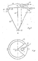
- Fig. 1 und 2 Absetzbehälter eines erfindungsgemäßen Trennscheiders,
- Fig. 3 und 4 einen weiteren Absetzbehälter,
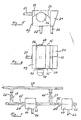
- Fig. 5 und 6 ein nachgeschaltetes Trommelsieb des erfindungsgemäßen Trennscheiders,
- Fig. 7 eine Hintereinanderschaltung verschiedener Behälter nach Fig. 1-6 mit der Möglichkeit zur Schlackenrückführung zum Reaktor.
- 1 and 2 settling tanks of a separator according to the invention,
- 3 and 4 a further settling tank,
- 5 and 6 a downstream drum screen of the separator according to the invention,
- Fig. 7 shows a series connection of various containers according to Fig. 1-6 with the possibility of slag return to the reactor.
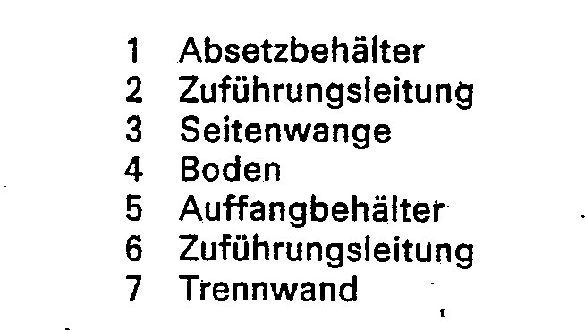
In Fig. 1 und 2 ist mit 1 ein Absetzbehälter bezeichnet. Der Absetzbehälter 1 steht aufrecht mit seinem spitzen Ende nach unten; beide Enden sind offen. Am oberen Ende des Absetzbehälters 1 ist zentrisch in dem Absetzbehälter 1 eine Zuführungsleitung 2 angeordnet. Die Zuführungsleitung 2 wird durch Seitenwangen 3 in dem Absetzbehälter 1 gehalten, die in radialer Richtung des Absetzbehälters 1 schließend über der ganzen Länge an der Zuführungsleitung 2 und an der gegenüberliegenden Behälterinnenwand anliegen. Zweckmäßigerweise sind die Seitenwangen 3 an der Behälterinnenwand und Zuführungsleitung 2 verschweißt. Unten an den Seitenwangen 3 befindet sich ein Boden 4. Der Boden 4 schließt dicht mit den Seitenwangen 3, der Zuführungsleitung 2 und der Behälterinnenwand ab. Er ist vorzugsweise mit diesen Teilen verschweißt. Der Boden 4 bildet mit den Seitenwangen 3, der von den Seitenwangen 3 und dem Boden 4 eingeschlossenen Rohrwandung sowie der eingeschlossenen Zuführungsleitung 2 einen Auffangbehälter 5.1 and 2, 1 is a settling tank. The
Zu der Zuführungsleitung 2 führt eine Zuführungsleitung 6 für mit Schlacke beladenes Wasser. Dieses Wasser stammt aus dem Wasserbad eines einem Vergasungsreaktor einer Kohlevergasungsanlage unmittelbar nachgeschalteten Strahlungskessels.A feed line 6 for water loaded with slag leads to the
Dabei besitzen der Vergasungsreaktor und der Strahlungskessel im wesentlichen zylindrische Formen und sind fluchtend übereinander angeordnet, so daß die aus dem Reaktor austretenden Schlackenpartikel senkrecht nach unten in den Strahlungskessel strömen können und dort eine erste Abkühlung erfahren. Im Fuß des Strahlungskessels befindet sich das Wasserbad.The gasification reactor and the radiation vessel have essentially cylindrical shapes and are aligned one above the other so that the slag particles emerging from the reactor can flow vertically downward into the radiation vessel and are cooled there for the first time. The water bath is located in the foot of the radiation boiler.
Das bei einer Kohlevergasung entstandene Gas und die von dem Gas mitgeführten Schlackenpartikel strömen gegen den Badspiegel des Wasserbades. Dabei wird das Gas an dem Badspiegel des Wasserbades umgelenkt, während die mitgeführten Schlackenpartikel infolge ihrer Massenträgheit in das Wasserbad schlagen und sich dort sammeln.The gas generated in coal gasification and the slag particles carried by the gas flow against the bath level of the water bath. The gas is redirected at the bath level of the water bath, while the slag particles carried hit by the mass inertia in the water bath and collect there.
Die Schlackenpartikel werden mit dem Wasser am unteren Ende des Strahlungskessels abgezogen. Das geschieht bei einer Kohlevergasung unter Überdruck mit Hilfe einer Schleuse. Das heißt, zunächst wird das untere Ende des Strahlungskessels, an das sich das obere Ende der Schleuse anschließt, geöffnet. Dadurch kann die Schlacke aus dem unteren Ende des Strahlungskessels in die Schleuse abfließen. Nach Entleerung der Schlackenpartikel aus dem Wasserbad wird dessen Ende bzw. das obere Ende der Schleuse wieder geschlossen. Es wird nur soviel Wasser ausgeschleust, wie es einer Schleusenfüllung entspricht. Das restliche Wasser des Wasserbades dient aus Sicherheitsgründen als Gassperre. Anschließend können das untere Ende der Schleuse geöffnet und die Schlacke mitsamt dem Wasser aus der Schleuse bei atmosphärischem bzw. geringfügigem Überdruck abgezogen werden.The slag particles are drawn off with the water at the lower end of the radiation boiler. In the case of coal gasification under pressure, this is done with the help of a lock. This means that the lower end of the radiation boiler, which is connected to the upper end of the lock, is opened first. This allows the slag to flow out of the lower end of the radiation boiler into the lock. After emptying the slag particles from the water bath, its end or the upper end of the lock is closed again. Only as much water is removed as corresponds to a lock filling. The remaining water in the water bath serves as a gas barrier for safety reasons. The lower end of the lock can then be opened and the slag together with the water can be removed from the lock at atmospheric or slight excess pressure.
Die Schleuse erfüllt einen doppelten Zweck. Sie ist Druckschleuse. Als Druckschleuse ermöglicht sie es, die Schlacke aus der Überdruckatmosphäre des Reaktor- und Strahlungskesselinnenraumes abzuziehen. Zugleich schützt sie das erzeugte Gas vor unerwünschten Beimengungen umgebender Atmosphäre bzw. die Umwelt vor nachteiligen Folgen ausströmenden Synthesegases.The lock serves a dual purpose. It is a pressure lock. As a pressure lock, it enables the slag to be drawn off from the overpressure atmosphere of the reactor and radiation boiler interior. At the same time, it protects the gas produced from undesirable admixtures of the surrounding atmosphere and the environment from the disadvantageous consequences of synthetic gas flowing out.
Das Schlacke führende Wasser aus dem Wasserbad des Strahlungskessels wird mit einer beispielsweise als Flügelrad oder Kolbenpumpe ausgebildeten Förderpumpe durch die Zuführungsleitungen 6, 2 des Absetzbehälters gedrückt.The water carrying the slag out of the water bath of the radiation boiler is forced through the
Die Zuführungsleitung 2 besitzt eine Trennwand 7. Die Trennwand 7 unterteilt den Rohrinnenraum in zwei Hälften und endet in der Mitte der Zuführungsleitung 2, d. h., erstreckt sich über die halbe Länge der Zuführungsleitung 2.The
Die aus der Zuführungsleitung 6 austretenden und infolge des Pumpendruckes zwangsweise nach unten in die Zuführungsleitung 2 strömenden Schlackenpartikel haben unterschiedliches Verdrängungsgewicht. Die einen Partikel besitzen infolge eines gegenüber dem Wasser geringeren Verdrängungsgewichtes Schwimmfähigkeit. Auf diese Partikel wirkt ständig eine Auftriebskraft. Diese Auftriebskraft wird in der Zuführungsleitung 6 durch den Pumpendruck überwunden. Am Ende der Trennwand 7 wird diesen Schlackenpartikeln Gelegenheit gegeben, aus der Zuführungsströmung auszubrechen und in dem gegenüberliegenden und mit 8 bezeichneten Abfluß wieder aufzusteigen. Die schwimmfähigen Schlackenpartikel gelangen dann aus dem Abfluß 8 in den Auffangbehälter 5.The slag particles emerging from the feed line 6 and forcibly flowing downward into the
Die Schlackenpartikel mit< dem gegenüber dem Wasser größeren Verdrängungsgewicht treten aus der Zuführungsleitung 2 nach unten aus und setzen ihre Bewegungsbahn zum unteren Ende des Absetzbehälters 1 hin fort. Am unteren Ende 9 des Absetzbehälters 1 sammeln sich diese Schlackenpartikel. Sie können dort kontinuierlich oder in Intervallen abgezogen werden. Das durch die Zuführungsleitung 6 zugeführte Wasser strömt über jeweils einen Überlauf 10 im Auffangbehälter 5 und einen Überlauf 11 im übrigen Behälterbereich in einen Abfluß und einen Klarwasserabfluß 13. Das durch den Klarwasserabfluß 13 ausströmende Wasser ist durch Sammeln der Schlackenpartikel am unteren Ende 9 des Absetzbehälters 1 gereinigt. Das aus dem Abfluß 12 austretende Wasser wird durch den Überlauf 10 von den schwimmfähigen Schlackenpartikeln gereinigt. Der Überlauf 10 hält die Schlackenpartikel zurück.The slag particles with a displacement weight greater than that of water emerge downward from the
Der Überlauf 10 und der Überlauf 11 werden durch einen gemeinsamen Ring im Absetzbehälter 1 gebildet, der durch die Seitenwangen 3 unterteilt ist.The
Der Abfluß 12 und die Leitung 12a sind mit einem Trommelsieb nach Fig. 5 und 6 verbunden. Nach Fig. 3 und 4 ist anstelle des Absetzbehälters 1 ein Absetzbehälter 29 vorgesehen. Der Absetzbehälter 29 steht aufrecht mit seinem spitzen Ende nach unten. Beide Enden sind offen. Am oberen Ende des Absetzbehälters 29 ist exzentrisch in dem Absetzbehälter eine Zuführungsleitung 38 angeordnet. Die Zuführungsleitung 38 befindet sich mittig in einer nach unten offenen Trennzone 31. Die Trennzone 31 wird durch die Seitenwangen 30 gebildet, die mit der Behälterwand und am Stoß miteinander verschweißt sind.The
Zu der Zuführungsleitung 38 führt eine Zuführungsleitung 32 für mit Schlacke beladenes Wasser. Das Schlacke führende Wasser wird mit einer beispielsweise als Flügelrad oder Kolbenpumpe ausgebildeten Förderpumpe durch die Zuführungsleitung 32 in die Zuführungsleitung 38 des Absetzbehälters 29 gedrückt.A
Das aus der Zuführungsleitung 32 austretende Schlackenwasser wird über die Zuführungsleitung 38 entspannt und auf die Wasseroberfläche der Trennzone 31 gegeben. Die einen Partikel besitzen infolge eines gegenüber dem Wasser geringeren Verdrängungsgewichtes Schwimmfähigkeit. Auf diese Partikel wirkt ständig eine Auftriebskraft. Diese Auftriebskraft bewirkt, daß diese Partikel an der Oberfläche bleiben. Ein Übertreten dieser Partikel in den Klarwasserabfluß 37 wird durch die höher als der Klarwasserbadspiegel und Überlauf 34 liegenden Kanten 35 der Seitenwangen 30 verhindert.The slag water emerging from the
Die Schlackenpartikel mit dem gegenüber dem Wasser größeren Verdrängungsgewicht treten aus der Zuführungsleitung 38 nach unten aus und setzen ihre Bewegungsbahn durch die Trennzone 31 zum unteren Ende des Absetzbehälters 29 hin fort. Am unteren Ende 33 des Absetzbehälters 29 sammeln sich diese Schlakkenpartikel. Sie können dort kontinuierlich oder in Intervallen abgezogen werden. Das durch die Zuführungsleitung 32 zugeführte Wasser strömt über den Überlauf 34.The slag particles with the displacement weight that is greater than the water emerge downward from the
Das durch den Klarwasserabfluß 37 ausströmende Wasser ist durch Sammeln der Schlakkenpartikel am unteren Ende 33 des Abflußbehälters 29 und das Sammeln der schwimmfähigen Schlackenpartikel in der Trennzone 31 gereinigt. Am Abfluß 36 können kontinuierlich oder in Intervallen die schwimmfähigen Partikel ausgetragen werden. Wahlweise wird außerdem ein mechanisch angetriebener Rechen an der Trennzone 31 angeordnet, der die schwimmfähigen Schlackenpartikel zusätzlich abzieht.The water flowing out through the clear water drain 37 is cleaned by collecting the slag particles at the
Fig. 5 und 6 zeigen ein nachgeschaltetes Trommelsieb. Die Vorrichtung nach Fig. 1 und 2 besteht aus einem kastenförmig ausgebildeten Auffangbehälter 14, in dessen Seitenwänden 15 ein Trommelsieb 16 drehbeweglich gelagert ist. Das Trommelsieb 16 ist beiderseits in Lagerflanschen 17 gehalten und an einer Seite mit einem Antriebsmotor 18 versehen. Der Antriebsmotor 18 dreht das Trommelsieb 16 kontinuierlich mit gleichbleibender Geschwindigkeit. Dabei gleitet das Trommelsieb 16 an zwei Blechen, von denen eines die Funktion eines Aufgabebleches 19 hat, während das andere eine- Rutsche 20 bildet. Die Rutsche 20 führt zu einem Sammelbehälter 21, an dessen Unterseite sich eine Leitung 22 zum Abziehen von gesammelten Schlackenpartikeln befindet. An der Unterseite des Auffangbehälters 14 befindet sich gleichfalls eine Leitung. Diese mit 23 bezeichnete Leitung dient zum Abziehen von Wasser. Ferner besitzt der Auffangbehälter 14 eine Wasser- und Schlakkenzuführungsleitung 24.5 and 6 show a downstream drum screen. 1 and 2 consists of a box-shaped
Im Betriebsfall wird Schlacke führendes Wasser durch die Zuführungsleitung 24 mit Hilfe einer Pumpe in den Auffangbehälter 14 gefördert. Dabei gelangt das Wasser mit den Schlackenpartikeln über das Aufgabeblech 19 auf den äußeren Umfang des sich im Uhrzeigersinn mit geringerer Geschwindigkeit drehenden Trommelsiebes 16.In operation, slag-carrying water is conveyed through the
Das Trommelsieb 16 fördert die Schlackenpartikel von dem Aufgabeblech 19 zur Rutsche 20, während das Wasser durch das Trommelsieb 16 hindurch zum Behälterboden strömt. Dort wird es durch die Leitung 23 hindurch abgezogen.The
Die an der Rutsche 20 ankommenden Schlakkenpartikel werden von dem Trommelsieb 16 abgestreift und gleiten auf der Rutsche 20 in den Sammelbehälter 21. Dort sammeln sie sich und können kontinuierlich oder in Zeitabschnitten durch die Leitung 22 hindurch einer beliebigen Verwendung zugeführt werden.The slag particles arriving at the
Damit die angeförderten Schlackenpartikel von dem Trommelsieb 16 abgestreift werden, gleitet die Rutsche 20 auf dem Trommelsieb 16 bzw. ist sie mit geringfügigem Spiel über dem Trommelsieb 16 angeordnet. Entsprechendes gilt für das Aufgabeblech 19, um ein unerwünschtes Hindurchtreten von Schlackenpartikeln zum Behälterboden zu verhindern.So that the slag particles conveyed off are stripped from the
Die Drehgeschwindigkeit und die Fördergeschwindigkeit für das Wasser und die Schlakkenpartikel sind so abgestimmt, daß der aufgabeseitige Wasserspiegel unterhalb der durch das Trommelsieb 16 gegebenen oberen Begrenzung steht.The rotational speed and the conveying speed for the water and the Schlakkenpartikel are coordinated so that the water level on the feed side is below the upper limit given by the
Um eine möglichst weitgehende Trocknung der Schlackenpartikel während des Trennvorganges zu erreichen, wird wahlweise die Rutsche 20 mit Sieböffnungen versehen, die ein zusätzliches Ablaufen von sich auf der Rutsche sammelnden Flüssigkeitstropfen ermöglichen.To as far as possible drying To reach the slag particles during the separation process, the
Im übrigen kann die Beaufschlagung des Trommelsiebes mit Schlacke führendem Wasser statt von außen auch von innen erfolgen. In einem solchen Fall ist das Trommelsieb 16 als Hohlzylinder ausgebildet und wird das Schlacke führende Wasser durch eine koaxial angeordnete Zuführungsleitung in das Innere des Trommelsiebes gelenkt. Dort tritt das Wasser durch das Trommelsieb hindurch in den umgebenden Behälter. Die Drehung des Trommelsiebes wirkt dabei beschleunigend auf die Trennung von Wasser und Schlackenpartikeln. Das austretende Wasser wird gegen die Wände des dann zweckmäßigerweise allseitig geschlossenen Sammelbehälters 14 geschleudert und strömt von den Wänden zum Behälterboden, wo es durch die Leitung 23 abgezogen wird.Otherwise, the slag-carrying water can be applied to the drum screen instead of from the inside. In such a case, the
Der Trennungsvorgang im Trommelsieb erfolgt kontinuierlich, d. h., es tritt kontinuierlich die vom Wasser weitgehend befreite Schlacke aus dem anderen Ende des Trommelsiebes aus, wenn der Auffangbehälter 14 mit dem Trommelsieb 16 geneigt angeordnet ist und statt des in Fig. 1 vorgesehenen, auf gleicher Welle sitzenden Antriebsmotors ein davon versetzt angeordneter Antriebsmotor über eine geeignete Transmission, z. B. einen Riemen oder Zahnradtrieb, das Trommelsieb 16 treibt. Der Riemen- oder Zahnradtrieb ermöglicht eine Trommelsieblagerung am äußeren Trommelsiebumfang mit einem außerhalb des Auffangbehälters 14 angeordneten Antriebsrad, das mit einer dem Innendurchmesser des Trommelsiebes gleichen Öffnung versehen ist. Dadurch können die Schlackenpartikel auf einer glatten Fläche ohne Hindernisse aus dem Trommelsieb 16 durch das Antriebsrad hindurch austreten. Die Zuführung des Schlacke führenden Wassers kann durch eine koaxiale Bohrung in der zum Lagerflansch 17 gehörenden Achse erfolgen.The separation process in the drum screen takes place continuously, i.e. that is, the slag largely freed of water continuously emerges from the other end of the drum screen when the collecting
Die Drehgeschwindigkeit des Trommelsiebes 16 ist bei Beaufschlagung des Trommelsiebes 16 von innen durch die auf die Schlackenpartikel wirkende Zentrifugalkraft und die Neigung des Trommelsiebes 16 bzw. des Auffangbehälters 14 begrenzt.The rotational speed of the
Im Falle der Beaufschlagung des Trommelsiebes 16 von außen sammeln sich alle Schlackenpartikel in dem Sammelbehälter 21. Die Schlakkenpartikel sammeln sich dagegen in einem dem Trommelsieb in aixaler Richtung nachgeordneten Sammelbehälter, wenn die Schlackenpartikel axial durch das Trommelsieb hindurchgeführt werden.If the
Die Nachschaltung des Sammelbehälters 14 hinter dem Absetzbehälter 1 bzw. 29 bewirkt eine Klassierung. Dazu ist die Zuführungsleitung 24 mit dem Abfluß 8 verbunden und sammeln sich Schlackenpartikel mit größerem Verdrängungsgewicht im Absetzbehälter 1, während sich Schlackenpartikel mit,kleinerem Verdrängungsgewicht im Sammelbehälter 21 sammeln. Eine weitere Klassierung des Schlackengutes läßt sich mit Hilfe einer Änderung der Strömungsgeschwindigkeit des Wassers und/oder der Sieböffnungen des Trommelsiebes bzw. der Rutsche 20 erreichen. Die Vergrößerung der Wassergeschwindigkeit führt zu einem Mitreißen kleinerer Schlackenpartikel über den Überlauf 10. Diese Schlackenpartikel sammeln sich bei Hintereinanderschaltung mehrerer Sammel- und Trennvorrichtungen in einem nachgeschalteten Sammel- bzw. Trennbehälter. Das heißt, das Prinzip dieser fortschreitenden Klassierung beruht auf mangelnder Funktionsfähigkeit der vorgeschalteten Trenn- und Sammelvorrichtungen. Die zu hohe Wassergeschwindigkeit verursacht die für diesen Vorgang nachlassende Sammel- und Trennfähigkeit der Vorrichtungen.The subsequent connection of the collecting
Unabhängig von der Wassergeschwindigkeit kann eine Klassierung mit unterschiedlichen Sieböffnungen bewirkt werden. Durch zunächst sehr große Sieböffnungen wird den kleinen Schlackenpartikeln Gelegenheit gegeben, mit dem Wasser durch das Trommelsieb 16 bzw. die Rutsche 20 hindurchzuströmen. Eine vorgeschaltete Sammel- und Trennvorrichtung spricht dann nur auf die größeren Partikel an. Die mit dem abgeschiedenen Wasser mitgeführten kleineren Schlackenpartikel können dann in einer oder mehreren nachgeschalteten weiteren Sammel-und Trennvorrichtungen abgeschieden werden. Durch Abstufen der Sieböffnungen von Vorrichtung zu Vorrichtung fallen die Schlackenpartikel nach Größen sortiert an.Regardless of the water speed, classification with different sieve openings can be achieved. The initially very large sieve openings give the small slag particles the opportunity to flow through the
Fig. 3 zeigt eine Hintereinanderschaltung verschiedener Trenn- und Sammelvorrichtungen. Das dargestellte Schema ist nachfolgend anhand der Auffangbehälter 14 erläutert. Danach befindet sich in jeder Zuführungsleitung 24 ein als Rohrschieber ausgebildetes Steuerventil 25.Fig. 3 shows a series connection of various separating and collecting devices. The diagram shown is explained below using the
Jeder Auffangbehälter 14 ist mit seiner Zuführungsleitung 24 an die Leitung 23 des vorgeschalteten Auffangbehälters 14 angeschlossen. Von den Leitungen 23, 24 führt eine Leitung 27 mit zwischengeschalteten Steuerventilen 26 zu einer Leitung 28. Mit Hilfe der Steuerventile 25 wird der Eingang der Auffangbehälter 14 geregelt. Je nach Ventilstellung tritt mehr oder weniger Schlacke führendes Wasser in die Auffangbehälter 14 ein. Das von jedem Steuerventil am Eintritt in den Auffangbehälter 14 gehinderte Wasser strömt mit den Schlackenpartikeln über die zugehörende Leitung 27 und das Steuerventil 26 in die Leitung 28. Andererseits kann der Flüssigkeitsstrom in den Leitungen 27 auch durch Verstellen der Steuerventile 26 beeinflußt werden.Each collecting
Bei unterschiedlichen Sieböffnungsgrößen in jedem Auffangbehälter 14, also zunächst größeren Sieböffnungen und von Behälter zu Behälter kleiner werdenden Sieböffnungen, fällt hinter jedem Auffangbehälter 14 Wasser mit anderen, verbleibenden kleineren Schlackenpartikein an.With different sieve opening sizes in each collecting
Dieses Wasser und diese Schlackenpartikel können durch Verstellen des Steuerventils 25 ganz oder teilweise in die vor dem zugehörenden Steuerventil 25 abzweigende Leitung 27 hindurch in die Leitung 28 geleitet werden.This water and these slag particles can be passed entirely or partially into the
Der bei teiiweisem Abzweigen des Wasser-und Partikelstromes verbleibende, in den nachfolgenden Auffangbehälter 14 gelangende Wasser- und Partikelstrom wird wiederum von Schlackenpartikeln bestimmter Größe befreit, nämlich denen, die an den Sieböffnungen dieses nachgeschalteten Auffangbehälters 14 hängenbleiben. Die mit dem durchströmenden Wasser mitgehenden Schlackenpartikel kleineren Formats treten durch die Leitungen 23 aus und können wiederum ganz oder teilweise der Leitung 28 zugeführt werden. Das geschieht mit Hilfe des dem nächsten Auffangbehälter 14 vorgeschalteten Steuerventils 25.The water and particle stream remaining in the partial branching off of the water and particle stream and reaching the
Die in allen Auffangbehältern 14 herausgesiebten Partikel werden durch die Leitungen 22 abgeführt. Sie gehen einer beliebigen Verwendung zu.The particles screened out in all the collecting
Die mit Wasser in die Leitung 28 gelangten Schlackenpartikel besitzen eine Korngrößenverteilung, die mit den Steuerventilen 25 und 26 so eingestellt ist, daß sie sich bei einer Schlackenrückführung aus der Leitung 28 in die Kohleaufgabe (Reaktoreintrag), insbesondere den dem Vergasungsreaktor vorgeschalteten Mischer für die Kohleaufbereitung, mit der Einsatzkohle optimal ergänzen. Die optimale Einstellung läßt sich von Hand durch probeweise Verstellung der Steuerventile 25 ermitteln.The slag particles which have reached water in
Die Schlackenpartikel werden zusammen mit dem Wasser in den Mischer gegeben, wenn die Einsatzkohle in die Form einer pumpfähigen Kohle-Wasserslurry gebracht werden soll. Dabei läßt sich der Wasseranteil aus der Leitung 28 durch Zwischenschaltung eines weiteren Trennscheiders in beliebiger Weise verrringern. Das geschieht entweder mit entsprechend verringerter Wasserabscheidefähigkeit oder aber durch teilweise Zugabe des abgeschiedenen Wassers nach Verlassen des Abscheidebehälters.The slag particles are added to the mixer together with the water if the insert coal is to be brought into the form of a pumpable coal-water slurry. The water content from
Vorzugsweise beschränkt sich die Rückführung von Schlackenpartikel zum Reaktor auf die schwimmfähigen Schlackenpartikel. Die schwimmfähigen Schlackenpartikel besitzen infolge unvollständigen Ausbrandes noch einen nutzbaren Kohlenstoffanteil.The return of slag particles to the reactor is preferably limited to the floatable slag particles. The floating slag particles still have a usable carbon content due to incomplete burnout.
Sofern zur Beeinflussung der Reaktortemperatur auch eine Beimengung von völlig ausgebrannten $chlackenpartikeln von Vorteil ist, ist eine zusätzliche Partikelzuführung in die Leitung 28 vorgesehen. Die zusätzliche Zuführung erfolgt über ein geeignetes Förderaggregat, z. B. eine Förderschnecke.

Claims (10)
Applications Claiming Priority (2)
| Application Number | Priority Date | Filing Date | Title |
|---|---|---|---|
| DE2851533 | 1978-11-29 | ||
| DE19782851533 DE2851533A1 (en) | 1978-11-29 | 1978-11-29 | COAL GASIFICATION PLANT |
Publications (2)
| Publication Number | Publication Date |
|---|---|
| EP0012461A1 EP0012461A1 (en) | 1980-06-25 |
| EP0012461B1 true EP0012461B1 (en) | 1983-06-15 |
Family
ID=6055775
Family Applications (1)
| Application Number | Title | Priority Date | Filing Date |
|---|---|---|---|
| EP79200698A Expired EP0012461B1 (en) | 1978-11-29 | 1979-11-29 | Coal gasification plant |
Country Status (9)
| Country | Link |
|---|---|
| EP (1) | EP0012461B1 (en) |
| JP (1) | JPS5598294A (en) |
| AU (1) | AU527886B2 (en) |
| BR (1) | BR7907720A (en) |
| CA (1) | CA1157652A (en) |
| DE (2) | DE2851533A1 (en) |
| PL (2) | PL126045B1 (en) |
| SU (1) | SU1036237A3 (en) |
| ZA (1) | ZA796488B (en) |
Families Citing this family (7)
| Publication number | Priority date | Publication date | Assignee | Title |
|---|---|---|---|---|
| BR8105270A (en) * | 1980-11-12 | 1982-08-31 | Texaco Development Corp | PROCESS FOR THE PRODUCTION OF SYNTHESIS GAS SUBSTANTIALLY FREE OF PARTICLES |
| CH661054A5 (en) * | 1981-10-23 | 1987-06-30 | Sulzer Ag | GAS COOLER TO SYNTHESIS GAS GENERATOR. |
| AU551376B2 (en) * | 1982-03-01 | 1986-04-24 | Energy Equipment Co. Ltd., The | Combustible gas producer plant |
| EP0124159B1 (en) * | 1983-05-02 | 1988-05-18 | Shell Internationale Researchmaatschappij B.V. | Process and apparatus for the preparation of synthesis gas |
| FR2546077B1 (en) * | 1983-05-20 | 1988-05-06 | Rhone Poulenc Chim Base | HIGH TEMPERATURE REACTION DEVICE |
| DE102008033095A1 (en) * | 2008-07-15 | 2010-01-28 | Uhde Gmbh | Apparatus for slag removal from a coal gasification reactor |
| JP6719971B2 (en) * | 2016-05-16 | 2020-07-08 | 三菱日立パワーシステムズ株式会社 | Slag discharge system, gasification furnace, and slag filtration method |
Family Cites Families (8)
| Publication number | Priority date | Publication date | Assignee | Title |
|---|---|---|---|---|
| FR656252A (en) * | 1926-05-27 | 1929-05-06 | Process and devices for treating carboniferous products | |
| DE1096302B (en) * | 1956-03-24 | 1961-01-05 | Basf Ag | Process for reprocessing grainy substances loaded with hydrophobic soot |
| DE2044310C3 (en) * | 1970-09-08 | 1974-01-31 | Texaco Development Corp., New York, N.Y. (V.St.A.) | Process for the production of carbon monoxide and hydrogen from solid fuel |
| DE2414389C3 (en) * | 1974-03-26 | 1978-03-16 | Hoechst Ag, 6000 Frankfurt | Coating agent made from a low molecular weight polytetrafluoroethylene and a film-forming resin in an organic solvent |
| US3929429A (en) * | 1974-09-26 | 1975-12-30 | Texaco Inc | Fuel gas from solid carbonaceous fuels |
| NL182486C (en) * | 1976-03-08 | 1988-03-16 | Shell Int Research | METHOD FOR PREPARING DRY SOOT AND APPARATUS SUITABLE FOR CARRYING OUT THIS METHOD |
| DE2735090C2 (en) * | 1977-08-04 | 1986-11-06 | Carl Still Gmbh & Co Kg, 4350 Recklinghausen | Process for cleaning and cooling process gases containing hydrogen and carbon oxide |
| DE2735565C2 (en) * | 1977-08-06 | 1986-01-02 | Carl Still Gmbh & Co Kg, 4350 Recklinghausen | Single-heat process for the generation of reducing gases consisting essentially of carbon oxide and hydrogen for ore reductions and apparatus for its implementation |
-
1978
- 1978-11-29 DE DE19782851533 patent/DE2851533A1/en not_active Withdrawn
-
1979
- 1979-11-27 PL PL1979235147A patent/PL126045B1/en unknown
- 1979-11-27 PL PL1979219914A patent/PL123992B1/en unknown
- 1979-11-27 JP JP15252079A patent/JPS5598294A/en active Pending
- 1979-11-28 SU SU792843409A patent/SU1036237A3/en active
- 1979-11-28 AU AU53264/79A patent/AU527886B2/en not_active Ceased
- 1979-11-28 BR BR7907720A patent/BR7907720A/en not_active IP Right Cessation
- 1979-11-29 EP EP79200698A patent/EP0012461B1/en not_active Expired
- 1979-11-29 CA CA000340910A patent/CA1157652A/en not_active Expired
- 1979-11-29 ZA ZA796488A patent/ZA796488B/en unknown
- 1979-11-29 DE DE7979200698T patent/DE2965692D1/en not_active Expired
Also Published As
| Publication number | Publication date |
|---|---|
| DE2965692D1 (en) | 1983-07-21 |
| ZA796488B (en) | 1981-01-28 |
| BR7907720A (en) | 1980-09-23 |
| PL126045B1 (en) | 1983-07-30 |
| PL123992B1 (en) | 1982-12-31 |
| AU5326479A (en) | 1980-09-04 |
| AU527886B2 (en) | 1983-03-31 |
| PL219914A1 (en) | 1980-09-08 |
| DE2851533A1 (en) | 1980-06-12 |
| CA1157652A (en) | 1983-11-29 |
| SU1036237A3 (en) | 1983-08-15 |
| EP0012461A1 (en) | 1980-06-25 |
| JPS5598294A (en) | 1980-07-26 |
Similar Documents
| Publication | Publication Date | Title |
|---|---|---|
| EP2155353B1 (en) | Press screw separator | |
| DE2930581A1 (en) | CENTRIFUGE FOR SORTING AND SEPARATING SOLIDS | |
| EP0322516A2 (en) | Solid bowl centrifuge | |
| DE1293089B (en) | centrifuge | |
| DE2813056C2 (en) | Washing drum for processing residual concrete | |
| EP0537797A1 (en) | Compact type-device for separating and removing rakings and sand from a gully | |
| WO2003078070A1 (en) | Helical conveyor centrifuge | |
| DE3518833C2 (en) | ||
| EP0012461B1 (en) | Coal gasification plant | |
| EP1566219B1 (en) | Device for cleaning and separating light and heavy articles contained in bulk material | |
| DE3301099C2 (en) | ||
| DE1024438B (en) | Process for separating solids from a liquid | |
| WO2001005718A1 (en) | Device for dehydrating sludge | |
| DE193997C (en) | ||
| DE4209277A1 (en) | DEVICE FOR SORTING SOLID MIXTURES | |
| DE4414750C2 (en) | Method and device for cleaning viscous plastic melts | |
| DE1632324A1 (en) | Funnel centrifuge | |
| WO1994004276A1 (en) | Conveyor for aggregates produced during reprocessing of residual concrete | |
| EP1137469B1 (en) | Device for separating waste water | |
| EP1860231A2 (en) | Method and device for cleaning paper raw materials containing impurities | |
| DE19622962A1 (en) | Device for separating composite material suspended in liquid | |
| DE2751425A1 (en) | AIR ROTARY SORTER | |
| DE3132740A1 (en) | FULL-COATED CENTRIFUGE WITH SEVEN PART | |
| DE2622987A1 (en) | METHOD AND DEVICE FOR SEPARATING A MATERIAL MIXTURE | |
| EP1161302B1 (en) | Installation and method for separating substance mixtures having different densities |
Legal Events
| Date | Code | Title | Description |
|---|---|---|---|
| PUAI | Public reference made under article 153(3) epc to a published international application that has entered the european phase |
Free format text: ORIGINAL CODE: 0009012 |
|
| AK | Designated contracting states |
Designated state(s): BE DE FR GB NL |
|
| 17P | Request for examination filed | ||
| GRAA | (expected) grant |
Free format text: ORIGINAL CODE: 0009210 |
|
| AK | Designated contracting states |
Designated state(s): BE DE FR GB NL |
|
| REF | Corresponds to: |
Ref document number: 2965692 Country of ref document: DE Date of ref document: 19830721 |
|
| ET | Fr: translation filed | ||
| PLBE | No opposition filed within time limit |
Free format text: ORIGINAL CODE: 0009261 |
|
| STAA | Information on the status of an ep patent application or granted ep patent |
Free format text: STATUS: NO OPPOSITION FILED WITHIN TIME LIMIT |
|
| 26N | No opposition filed | ||
| GBPC | Gb: european patent ceased through non-payment of renewal fee | ||
| PG25 | Lapsed in a contracting state [announced via postgrant information from national office to epo] |
Ref country code: GB Effective date: 19881118 |
|
| PGFP | Annual fee paid to national office [announced via postgrant information from national office to epo] |
Ref country code: DE Payment date: 19951025 Year of fee payment: 17 |
|
| PGFP | Annual fee paid to national office [announced via postgrant information from national office to epo] |
Ref country code: FR Payment date: 19951117 Year of fee payment: 17 |
|
| PGFP | Annual fee paid to national office [announced via postgrant information from national office to epo] |
Ref country code: NL Payment date: 19961129 Year of fee payment: 18 |
|
| PGFP | Annual fee paid to national office [announced via postgrant information from national office to epo] |
Ref country code: BE Payment date: 19970106 Year of fee payment: 18 |
|
| PG25 | Lapsed in a contracting state [announced via postgrant information from national office to epo] |
Ref country code: FR Effective date: 19970731 |
|
| PG25 | Lapsed in a contracting state [announced via postgrant information from national office to epo] |
Ref country code: DE Effective date: 19970801 |
|
| REG | Reference to a national code |
Ref country code: FR Ref legal event code: ST |
|
| PG25 | Lapsed in a contracting state [announced via postgrant information from national office to epo] |
Ref country code: BE Free format text: LAPSE BECAUSE OF NON-PAYMENT OF DUE FEES Effective date: 19971130 |
|
| BERE | Be: lapsed |
Owner name: RUHRKOHLE A.G. Effective date: 19971130 |
|
| PG25 | Lapsed in a contracting state [announced via postgrant information from national office to epo] |
Ref country code: NL Free format text: LAPSE BECAUSE OF NON-PAYMENT OF DUE FEES Effective date: 19980601 |
|
| NLV4 | Nl: lapsed or anulled due to non-payment of the annual fee |
Effective date: 19980601 |