EP0010965A1 - A squeeze-bottle, liquid-dispensing container - Google Patents
A squeeze-bottle, liquid-dispensing container Download PDFInfo
- Publication number
- EP0010965A1 EP0010965A1 EP79302399A EP79302399A EP0010965A1 EP 0010965 A1 EP0010965 A1 EP 0010965A1 EP 79302399 A EP79302399 A EP 79302399A EP 79302399 A EP79302399 A EP 79302399A EP 0010965 A1 EP0010965 A1 EP 0010965A1
- Authority
- EP
- European Patent Office
- Prior art keywords
- container
- receptacle
- duct
- liquid
- dispensing
- Prior art date
- Legal status (The legal status is an assumption and is not a legal conclusion. Google has not performed a legal analysis and makes no representation as to the accuracy of the status listed.)
- Granted
Links
Images

Classifications
-
- G—PHYSICS
- G01—MEASURING; TESTING
- G01F—MEASURING VOLUME, VOLUME FLOW, MASS FLOW OR LIQUID LEVEL; METERING BY VOLUME
- G01F11/00—Apparatus requiring external operation adapted at each repeated and identical operation to measure and separate a predetermined volume of fluid or fluent solid material from a supply or container, without regard to weight, and to deliver it
- G01F11/28—Apparatus requiring external operation adapted at each repeated and identical operation to measure and separate a predetermined volume of fluid or fluent solid material from a supply or container, without regard to weight, and to deliver it with stationary measuring chambers having constant volume during measurement
- G01F11/286—Apparatus requiring external operation adapted at each repeated and identical operation to measure and separate a predetermined volume of fluid or fluent solid material from a supply or container, without regard to weight, and to deliver it with stationary measuring chambers having constant volume during measurement where filling of the measuring chamber is effected by squeezing a supply container that is in fluid connection with the measuring chamber and excess fluid is sucked back from the measuring chamber during relaxation of the supply container
-
- B—PERFORMING OPERATIONS; TRANSPORTING
- B65—CONVEYING; PACKING; STORING; HANDLING THIN OR FILAMENTARY MATERIAL
- B65D—CONTAINERS FOR STORAGE OR TRANSPORT OF ARTICLES OR MATERIALS, e.g. BAGS, BARRELS, BOTTLES, BOXES, CANS, CARTONS, CRATES, DRUMS, JARS, TANKS, HOPPERS, FORWARDING CONTAINERS; ACCESSORIES, CLOSURES, OR FITTINGS THEREFOR; PACKAGING ELEMENTS; PACKAGES
- B65D25/00—Details of other kinds or types of rigid or semi-rigid containers
- B65D25/38—Devices for discharging contents
- B65D25/52—Devices for discharging successive articles or portions of contents
Definitions
- This invention relates to a dispensing container for liquids and provides an improved container for repeated delivery of a measured quantity of liquid.
- the invention is particularly but not exclusively useful for dispensing relatively large doses, such as 10-30 millilitres or more, for use in veterinary treatment.
- the invention is applied to a known kind of liquid-dispensing container formed integrally with a dispensing receptacle and having, extending between the container and the receptacle, a duct for liquid to be expressed from the container into the receptacle or sucked back by squeezing or relaxing squeeze of the container to change its volume.
- the duct is formed integrally with the container and receptacle.
- the duct integrally with the container and receptacle, preferably by moulding resiliently deformable plastics material, not only is there saved the cost of manufacture, insertion and securing of a separate duct, or a combined duct and receptable, as in previously proposed dispensing containers, but the location and inlet and outlet levels of the duct are determined once for all in the manufacture of the container. This avoids uncertainty in the measuring of dispensed quantities, in cases in which the outlet level of the duct determines the quantity dispensed, and also avoids the container becoming unserviceable should the duct be materially displaced or lost.
- the container is formed from thermoplastic material, such as polyethylene or polypropylene, by blow-moulding to define the duct by opposed and interwelded wall portions of the container.
- thermoplastic material such as polyethylene or polypropylene
- the duct extends upwardly externally alongside the container from an inlet through the container wall near the bottom thereof to an outlet opening into a receptacle formed on a shoulder of the container.
- the container illustrated is made by known blow-moulding technology in which a tubular parison of thermoplastic material is extruded and then blown while pressed between a pair of dies to flatten and interweld opposed wall portions, around the hollow shapes of the container, receptacle and duct, and cut off any material excess to the required overall shape.
- the container 1 is formed integrally with a duct 2 which extends, from a bottom inlet 3, upwards externally alongside the container and is defined by opposed wall portions of the container flattened and interwelded to form web portions 4 and 5 which similarly define a dispensing receptacle 6, into which the duct 2 opens by an outlet 7, integrally moulded on the shoulder of the container.
- Fig. 2 the webs 4 and 5 are shown as composed of two distinct layers but this is only for the purposes of illustration, the moulded material in the webs being in practice homogenously interwelded.
- the mould parting line along the meeting plane of the moulding tools is indicated by the broken line X-X in Fig. 2.
- the container is moulded with a screw-threaded neck 8, for a closure cap 9, and the receptacle 6 similarly has a neck 10 for a cap 11.
- the wall of the receptacle 6 is shown moulded with graduation marks 12, to indicate the levels for given volumes of liquid to be dispensed.
- the material of the whole container is transparent or translucent.
- the container is delivered to the user filled with liquid to be dispensed, or may be filled or re-filled through the neck 8, and may be used in the following manner to dispense a full measure from the receptacle 6.
- the container After removing or loosening the receptacle cap 11, and making sure that the container cap 9 is tightly closed, the container is squeezed, as indicated by the arrow S in Fig. 3 to reduce its volume and express liquid through the duct 2 into the receptacle 6 until it is seen that the duct outlet 7 is immersed.
- the container On release from squeezing, as indicated by the arrow R in Fig. 4, the container recovers its volume and liquid is sucked back through the duct 2 until the liquid level in the receptable 6 is reduced to the outlet 7 through which air, not liquid, is then inspired.
- the measured amount of liquid can be poured from the receptacle 6 (Fig.5).
- liquid may be returned from the receptacle to the container by tilting for liquid to flow back through the duct 2, the caps 9 and 11 being loosened.
Landscapes
- Engineering & Computer Science (AREA)
- Mechanical Engineering (AREA)
- Physics & Mathematics (AREA)
- Fluid Mechanics (AREA)
- General Physics & Mathematics (AREA)
- Closures For Containers (AREA)
- Containers And Packaging Bodies Having A Special Means To Remove Contents (AREA)
Abstract
Description
- This invention relates to a dispensing container for liquids and provides an improved container for repeated delivery of a measured quantity of liquid.
- The invention is particularly but not exclusively useful for dispensing relatively large doses, such as 10-30 millilitres or more, for use in veterinary treatment.
- The invention is applied to a known kind of liquid-dispensing container formed integrally with a dispensing receptacle and having, extending between the container and the receptacle, a duct for liquid to be expressed from the container into the receptacle or sucked back by squeezing or relaxing squeeze of the container to change its volume. According to the invention, the duct is formed integrally with the container and receptacle.
- By forming the duct integrally with the container and receptacle, preferably by moulding resiliently deformable plastics material, not only is there saved the cost of manufacture, insertion and securing of a separate duct, or a combined duct and receptable, as in previously proposed dispensing containers, but the location and inlet and outlet levels of the duct are determined once for all in the manufacture of the container. This avoids uncertainty in the measuring of dispensed quantities, in cases in which the outlet level of the duct determines the quantity dispensed, and also avoids the container becoming unserviceable should the duct be materially displaced or lost.
- Preferably the container is formed from thermoplastic material, such as polyethylene or polypropylene, by blow-moulding to define the duct by opposed and interwelded wall portions of the container.
- In a preferred embodiment, considering the container in an upright position, the duct extends upwardly externally alongside the container from an inlet through the container wall near the bottom thereof to an outlet opening into a receptacle formed on a shoulder of the container.
- The invention is illustrated by way of example on the accompanying drawings, in which:-
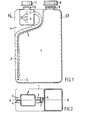
- Fig. 1 is a side elevation of a container according to the invention,
- Fig. 2 is a cross section on the line II - II of Fig. 1 and
- Figs. 3 to 5 are somewhat diagrammatic side elevations of the container of Fig. 1 in successive conditions of use.
- The container illustrated is made by known blow-moulding technology in which a tubular parison of thermoplastic material is extruded and then blown while pressed between a pair of dies to flatten and interweld opposed wall portions, around the hollow shapes of the container, receptacle and duct, and cut off any material excess to the required overall shape.
- As shown by Figs. 1 and 2, the
container 1 is formed integrally with aduct 2 which extends, from abottom inlet 3, upwards externally alongside the container and is defined by opposed wall portions of the container flattened and interwelded to formweb portions dispensing receptacle 6, into which theduct 2 opens by an outlet 7, integrally moulded on the shoulder of the container. - In Fig. 2 the
webs - The container is moulded with a screw-threaded
neck 8, for aclosure cap 9, and thereceptacle 6 similarly has aneck 10 for a cap 11. The wall of thereceptacle 6 is shown moulded with graduation marks 12, to indicate the levels for given volumes of liquid to be dispensed. The material of the whole container is transparent or translucent. - The container is delivered to the user filled with liquid to be dispensed, or may be filled or re-filled through the
neck 8, and may be used in the following manner to dispense a full measure from thereceptacle 6. - After removing or loosening the receptacle cap 11, and making sure that the
container cap 9 is tightly closed, the container is squeezed, as indicated by the arrow S in Fig. 3 to reduce its volume and express liquid through theduct 2 into thereceptacle 6 until it is seen that the duct outlet 7 is immersed. - On release from squeezing, as indicated by the arrow R in Fig. 4, the container recovers its volume and liquid is sucked back through the
duct 2 until the liquid level in the receptable 6 is reduced to the outlet 7 through which air, not liquid, is then inspired. - The cap 11 being removed, the measured amount of liquid can be poured from the receptacle 6 (Fig.5).
- By judicious squeezing, less than a full measure, as observed against the graduation marks 12, may be dispensed. Also, provided that the liquid is at a suitably low level in the
container 1, liquid may be returned from the receptacle to the container by tilting for liquid to flow back through theduct 2, thecaps 9 and 11 being loosened.
Claims (5)
Applications Claiming Priority (2)
| Application Number | Priority Date | Filing Date | Title |
|---|---|---|---|
| GB4292178 | 1978-11-02 | ||
| GB7842921A GB2038779B (en) | 1978-11-02 | 1978-11-02 | Dispensing container |
Publications (2)
| Publication Number | Publication Date |
|---|---|
| EP0010965A1 true EP0010965A1 (en) | 1980-05-14 |
| EP0010965B1 EP0010965B1 (en) | 1982-05-05 |
Family
ID=10500753
Family Applications (1)
| Application Number | Title | Priority Date | Filing Date |
|---|---|---|---|
| EP19790302399 Expired EP0010965B1 (en) | 1978-11-02 | 1979-11-01 | A squeeze-bottle, liquid-dispensing container |
Country Status (3)
| Country | Link |
|---|---|
| EP (1) | EP0010965B1 (en) |
| DE (1) | DE2962732D1 (en) |
| GB (1) | GB2038779B (en) |
Cited By (17)
| Publication number | Priority date | Publication date | Assignee | Title |
|---|---|---|---|---|
| EP0060060A2 (en) * | 1981-03-02 | 1982-09-15 | Bettix Limited | Dispensing container |
| US4640441A (en) * | 1984-05-14 | 1987-02-03 | Lever Brothers Company | Liquid-dispensing container |
| WO1993003338A1 (en) * | 1991-08-06 | 1993-02-18 | Anglehart, Dwight | Viscous liquid dispenser with integral measuring device |
| WO1994016969A1 (en) * | 1993-01-29 | 1994-08-04 | Roussel Uclaf | Multiple package for the simultaneous administration of two or more liquids in a preparation |
| WO1998008753A2 (en) * | 1996-08-19 | 1998-03-05 | Bettix Limited | Dispenser bag |
| EP0875461A1 (en) * | 1997-05-02 | 1998-11-04 | Soplar Sa | Bottle, especially for cleaning toilet bowls |
| WO1999019222A1 (en) * | 1997-10-10 | 1999-04-22 | Bettix Limited | Improved dispenser bag |
| WO1999067632A1 (en) * | 1998-06-20 | 1999-12-29 | Sensalyse Limited | Analysis of liquid samples |
| WO2001036921A1 (en) * | 1999-11-18 | 2001-05-25 | Alpla-Werke Alwin Lehner Gmbh & Co. Kg | Squeezable bottle comprising a dosing chamber |
| US6290102B1 (en) | 2000-03-31 | 2001-09-18 | Robert Michael Jennings | Liquid measuring and dispensing container |
| WO2002074636A1 (en) * | 2001-03-16 | 2002-09-26 | Fabrizio Arizzi | Multiple container |
| GB2389098A (en) * | 2002-05-08 | 2003-12-03 | Craig Driver | Dispensing container |
| WO2004031734A1 (en) * | 2002-10-03 | 2004-04-15 | The Secretary Of State For Defence | Sampling apparatus |
| EP1832878A1 (en) * | 2006-03-07 | 2007-09-12 | Hamilton Bonaduz AG | Container with a tamper-proof data transponder |
| EP2413108A1 (en) * | 2010-07-27 | 2012-02-01 | Pont Emballage | Metering device |
| ITVI20130312A1 (en) * | 2013-12-24 | 2015-06-25 | Taplast Srl | CONTAINER FOR A PRODUCT THAT CAN BE ASSOCIATED WITH A DISTRIBUTION DEVICE FOR SUCH A PRODUCT AND ITS RELEASE SYSTEM. |
| US9630828B1 (en) * | 2012-09-21 | 2017-04-25 | Michael A. Gardner | Multi shot fluid dispensing system |
Families Citing this family (10)
| Publication number | Priority date | Publication date | Assignee | Title |
|---|---|---|---|---|
| US4564129A (en) * | 1983-01-27 | 1986-01-14 | Hoechst-Roussel Pharmaceuticals Inc. | Dosage dispensing unit |
| US4600130A (en) * | 1983-09-29 | 1986-07-15 | Libit Sidney M | Squeeze pressure dispenser with integral siphon tube |
| US5071039A (en) * | 1990-03-16 | 1991-12-10 | Dwight Anglehart | Viscous liquid dispensing container |
| US5125541A (en) * | 1990-06-28 | 1992-06-30 | Dwight Angelhart | Viscous liquid dispensing apparatus |
| US5558257A (en) * | 1994-10-03 | 1996-09-24 | W. Braun Company | Oval integral slant pump |
| US5833124A (en) * | 1996-05-21 | 1998-11-10 | Pfizer Inc. | Fluid dispensing device |
| GB2340236B (en) * | 1998-06-20 | 2003-03-26 | Sensalyse Ltd | Analysis of liquid samples |
| US9051073B2 (en) | 2006-12-21 | 2015-06-09 | Robert M. Jennings | Measuring and dispensing container |
| US20120018458A1 (en) | 2010-07-26 | 2012-01-26 | Ecolab Usa Inc. | Metered dosing bottle |
| US11052415B2 (en) | 2016-03-10 | 2021-07-06 | Ecolab Usa Inc. | Measured dosing and spray bottle for multi-use applications and associated method of using |
Citations (3)
| Publication number | Priority date | Publication date | Assignee | Title |
|---|---|---|---|---|
| FR1393789A (en) * | 1963-04-22 | 1965-03-26 | Vessels for measuring and dispensing selected quantities of fluids or flowing materials such as fluids | |
| FR88270E (en) * | 1965-03-24 | 1967-01-06 | Hollow plastic body and shell mold for manufacturing them | |
| DE2710639A1 (en) * | 1977-03-11 | 1978-09-14 | Paul Banaschik | Package with metering device - has small metering compartment with outlet connected to large main compartment |
-
1978
- 1978-11-02 GB GB7842921A patent/GB2038779B/en not_active Expired
-
1979
- 1979-11-01 DE DE7979302399T patent/DE2962732D1/en not_active Expired
- 1979-11-01 EP EP19790302399 patent/EP0010965B1/en not_active Expired
Patent Citations (3)
| Publication number | Priority date | Publication date | Assignee | Title |
|---|---|---|---|---|
| FR1393789A (en) * | 1963-04-22 | 1965-03-26 | Vessels for measuring and dispensing selected quantities of fluids or flowing materials such as fluids | |
| FR88270E (en) * | 1965-03-24 | 1967-01-06 | Hollow plastic body and shell mold for manufacturing them | |
| DE2710639A1 (en) * | 1977-03-11 | 1978-09-14 | Paul Banaschik | Package with metering device - has small metering compartment with outlet connected to large main compartment |
Cited By (21)
| Publication number | Priority date | Publication date | Assignee | Title |
|---|---|---|---|---|
| EP0060060A2 (en) * | 1981-03-02 | 1982-09-15 | Bettix Limited | Dispensing container |
| EP0060060B1 (en) * | 1981-03-02 | 1987-10-21 | Bettix Limited | Dispensing container |
| US4640441A (en) * | 1984-05-14 | 1987-02-03 | Lever Brothers Company | Liquid-dispensing container |
| WO1993003338A1 (en) * | 1991-08-06 | 1993-02-18 | Anglehart, Dwight | Viscous liquid dispenser with integral measuring device |
| WO1994016969A1 (en) * | 1993-01-29 | 1994-08-04 | Roussel Uclaf | Multiple package for the simultaneous administration of two or more liquids in a preparation |
| WO1998008753A2 (en) * | 1996-08-19 | 1998-03-05 | Bettix Limited | Dispenser bag |
| WO1998008753A3 (en) * | 1996-08-19 | 1998-04-16 | Bettix Ltd | Dispenser bag |
| EP0875461A1 (en) * | 1997-05-02 | 1998-11-04 | Soplar Sa | Bottle, especially for cleaning toilet bowls |
| WO1999019222A1 (en) * | 1997-10-10 | 1999-04-22 | Bettix Limited | Improved dispenser bag |
| WO1999067632A1 (en) * | 1998-06-20 | 1999-12-29 | Sensalyse Limited | Analysis of liquid samples |
| WO2001036921A1 (en) * | 1999-11-18 | 2001-05-25 | Alpla-Werke Alwin Lehner Gmbh & Co. Kg | Squeezable bottle comprising a dosing chamber |
| US6290102B1 (en) | 2000-03-31 | 2001-09-18 | Robert Michael Jennings | Liquid measuring and dispensing container |
| WO2002074636A1 (en) * | 2001-03-16 | 2002-09-26 | Fabrizio Arizzi | Multiple container |
| GB2389098A (en) * | 2002-05-08 | 2003-12-03 | Craig Driver | Dispensing container |
| WO2004031734A1 (en) * | 2002-10-03 | 2004-04-15 | The Secretary Of State For Defence | Sampling apparatus |
| EP1832878A1 (en) * | 2006-03-07 | 2007-09-12 | Hamilton Bonaduz AG | Container with a tamper-proof data transponder |
| EP2413108A1 (en) * | 2010-07-27 | 2012-02-01 | Pont Emballage | Metering device |
| FR2963423A1 (en) * | 2010-07-27 | 2012-02-03 | Pont Emballage | ASSAY DEVICE |
| US9630828B1 (en) * | 2012-09-21 | 2017-04-25 | Michael A. Gardner | Multi shot fluid dispensing system |
| ITVI20130312A1 (en) * | 2013-12-24 | 2015-06-25 | Taplast Srl | CONTAINER FOR A PRODUCT THAT CAN BE ASSOCIATED WITH A DISTRIBUTION DEVICE FOR SUCH A PRODUCT AND ITS RELEASE SYSTEM. |
| WO2015097606A3 (en) * | 2013-12-24 | 2015-10-22 | Taplast S.P.A. | Product container suited to be associated with a dispensing device suited to dispense said product and related dispensing system |
Also Published As
| Publication number | Publication date |
|---|---|
| GB2038779B (en) | 1982-11-03 |
| EP0010965B1 (en) | 1982-05-05 |
| GB2038779A (en) | 1980-07-30 |
| DE2962732D1 (en) | 1982-06-24 |
Similar Documents
| Publication | Publication Date | Title |
|---|---|---|
| EP0010965A1 (en) | A squeeze-bottle, liquid-dispensing container | |
| US3347420A (en) | Multi-compartment container for dispensing measured quantities of a plurality of liquids | |
| US5054660A (en) | Self-dosing measuring chamber and container | |
| US3033420A (en) | Method and apparatus for dispensing liquids | |
| US4418843A (en) | Single-mouth squeeze-bottle dispensing container | |
| US3246807A (en) | Containers | |
| US3141574A (en) | Container for dispensing selected quantities of fluid | |
| US5220949A (en) | Bottle reflling apparatus | |
| EP0117423B1 (en) | Dosage dispensing unit | |
| US2979236A (en) | Dispenser caps for fluid containers | |
| US10232971B2 (en) | Measuring and dispensing container | |
| US4640441A (en) | Liquid-dispensing container | |
| US3402860A (en) | Combination closure and liquid metering dispenser for squeeze bottles | |
| US6378741B1 (en) | Dosing bottle for dispensing fixed doses of liquids | |
| US5071039A (en) | Viscous liquid dispensing container | |
| EP0666225A2 (en) | A container set comprising at least two containers | |
| EP0108636A2 (en) | Dispenser with self-sealing applicator | |
| US5125541A (en) | Viscous liquid dispensing apparatus | |
| CA1146507A (en) | Dispensing container | |
| WO1993003338A1 (en) | Viscous liquid dispenser with integral measuring device | |
| GB2129774A (en) | Dispensing container | |
| EP0701108A1 (en) | A metering device | |
| JPH0826319A (en) | Measuring cap | |
| JPH0118524Y2 (en) | ||
| JPS59134170A (en) | Crush type liquid distributing vessel |
Legal Events
| Date | Code | Title | Description |
|---|---|---|---|
| PUAI | Public reference made under article 153(3) epc to a published international application that has entered the european phase |
Free format text: ORIGINAL CODE: 0009012 |
|
| AK | Designated contracting states |
Designated state(s): BE DE FR GB IT |
|
| 17P | Request for examination filed |
Effective date: 19801105 |
|
| ITF | It: translation for a ep patent filed |
Owner name: BARZANO' E ZANARDO ROMA S.P.A. |
|
| GRAA | (expected) grant |
Free format text: ORIGINAL CODE: 0009210 |
|
| AK | Designated contracting states |
Designated state(s): BE DE FR GB IT |
|
| REF | Corresponds to: |
Ref document number: 2962732 Country of ref document: DE Date of ref document: 19820624 |
|
| ITTA | It: last paid annual fee | ||
| ITPR | It: changes in ownership of a european patent |
Owner name: ATTO DI LICENZA ESCLUSIVA;PLASTIVALLE S.R.L. |
|
| PGFP | Annual fee paid to national office [announced via postgrant information from national office to epo] |
Ref country code: GB Payment date: 19981021 Year of fee payment: 20 |
|
| PGFP | Annual fee paid to national office [announced via postgrant information from national office to epo] |
Ref country code: FR Payment date: 19981030 Year of fee payment: 20 |
|
| PGFP | Annual fee paid to national office [announced via postgrant information from national office to epo] |
Ref country code: BE Payment date: 19981204 Year of fee payment: 20 |
|
| PGFP | Annual fee paid to national office [announced via postgrant information from national office to epo] |
Ref country code: DE Payment date: 19981217 Year of fee payment: 20 |
|
| BE20 | Be: patent expired |
Free format text: 19991101 *BETTIX LTD |
|
| PG25 | Lapsed in a contracting state [announced via postgrant information from national office to epo] |
Ref country code: GB Free format text: LAPSE BECAUSE OF EXPIRATION OF PROTECTION Effective date: 19991031 |
|
| REG | Reference to a national code |
Ref country code: GB Ref legal event code: PE20 Effective date: 19991031 |
|
| PLBE | No opposition filed within time limit |
Free format text: ORIGINAL CODE: 0009261 |
|
| STAA | Information on the status of an ep patent application or granted ep patent |
Free format text: STATUS: NO OPPOSITION FILED WITHIN TIME LIMIT |