EP0010925B1 - Spray or atomizing nozzle - Google Patents
Spray or atomizing nozzle Download PDFInfo
- Publication number
- EP0010925B1 EP0010925B1 EP79302325A EP79302325A EP0010925B1 EP 0010925 B1 EP0010925 B1 EP 0010925B1 EP 79302325 A EP79302325 A EP 79302325A EP 79302325 A EP79302325 A EP 79302325A EP 0010925 B1 EP0010925 B1 EP 0010925B1
- Authority
- EP
- European Patent Office
- Prior art keywords
- spray
- nozzle
- control body
- orifice
- active face
- Prior art date
- Legal status (The legal status is an assumption and is not a legal conclusion. Google has not performed a legal analysis and makes no representation as to the accuracy of the status listed.)
- Expired
Links
Images


Classifications
-
- B—PERFORMING OPERATIONS; TRANSPORTING
- B05—SPRAYING OR ATOMISING IN GENERAL; APPLYING FLUENT MATERIALS TO SURFACES, IN GENERAL
- B05B—SPRAYING APPARATUS; ATOMISING APPARATUS; NOZZLES
- B05B3/00—Spraying or sprinkling apparatus with moving outlet elements or moving deflecting elements
- B05B3/02—Spraying or sprinkling apparatus with moving outlet elements or moving deflecting elements with rotating elements
- B05B3/04—Spraying or sprinkling apparatus with moving outlet elements or moving deflecting elements with rotating elements driven by the liquid or other fluent material discharged, e.g. the liquid actuating a motor before passing to the outlet
- B05B3/0417—Spraying or sprinkling apparatus with moving outlet elements or moving deflecting elements with rotating elements driven by the liquid or other fluent material discharged, e.g. the liquid actuating a motor before passing to the outlet comprising a liquid driven rotor, e.g. a turbine
- B05B3/0425—Spraying or sprinkling apparatus with moving outlet elements or moving deflecting elements with rotating elements driven by the liquid or other fluent material discharged, e.g. the liquid actuating a motor before passing to the outlet comprising a liquid driven rotor, e.g. a turbine actuated downstream of the outlet elements
- B05B3/0426—Spraying or sprinkling apparatus with moving outlet elements or moving deflecting elements with rotating elements driven by the liquid or other fluent material discharged, e.g. the liquid actuating a motor before passing to the outlet comprising a liquid driven rotor, e.g. a turbine actuated downstream of the outlet elements the liquid driven rotor being a deflecting rotating element
-
- B—PERFORMING OPERATIONS; TRANSPORTING
- B05—SPRAYING OR ATOMISING IN GENERAL; APPLYING FLUENT MATERIALS TO SURFACES, IN GENERAL
- B05B—SPRAYING APPARATUS; ATOMISING APPARATUS; NOZZLES
- B05B1/00—Nozzles, spray heads or other outlets, with or without auxiliary devices such as valves, heating means
- B05B1/26—Nozzles, spray heads or other outlets, with or without auxiliary devices such as valves, heating means with means for mechanically breaking-up or deflecting the jet after discharge, e.g. with fixed deflectors; Breaking-up the discharged liquid or other fluent material by impinging jets
- B05B1/262—Nozzles, spray heads or other outlets, with or without auxiliary devices such as valves, heating means with means for mechanically breaking-up or deflecting the jet after discharge, e.g. with fixed deflectors; Breaking-up the discharged liquid or other fluent material by impinging jets with fixed deflectors
- B05B1/265—Nozzles, spray heads or other outlets, with or without auxiliary devices such as valves, heating means with means for mechanically breaking-up or deflecting the jet after discharge, e.g. with fixed deflectors; Breaking-up the discharged liquid or other fluent material by impinging jets with fixed deflectors the liquid or other fluent material being symmetrically deflected about the axis of the nozzle
-
- B—PERFORMING OPERATIONS; TRANSPORTING
- B05—SPRAYING OR ATOMISING IN GENERAL; APPLYING FLUENT MATERIALS TO SURFACES, IN GENERAL
- B05B—SPRAYING APPARATUS; ATOMISING APPARATUS; NOZZLES
- B05B1/00—Nozzles, spray heads or other outlets, with or without auxiliary devices such as valves, heating means
- B05B1/34—Nozzles, spray heads or other outlets, with or without auxiliary devices such as valves, heating means designed to influence the nature of flow of the liquid or other fluent material, e.g. to produce swirl
- B05B1/3405—Nozzles, spray heads or other outlets, with or without auxiliary devices such as valves, heating means designed to influence the nature of flow of the liquid or other fluent material, e.g. to produce swirl to produce swirl
- B05B1/341—Nozzles, spray heads or other outlets, with or without auxiliary devices such as valves, heating means designed to influence the nature of flow of the liquid or other fluent material, e.g. to produce swirl to produce swirl before discharging the liquid or other fluent material, e.g. in a swirl chamber upstream the spray outlet
- B05B1/3421—Nozzles, spray heads or other outlets, with or without auxiliary devices such as valves, heating means designed to influence the nature of flow of the liquid or other fluent material, e.g. to produce swirl to produce swirl before discharging the liquid or other fluent material, e.g. in a swirl chamber upstream the spray outlet with channels emerging substantially tangentially in the swirl chamber
- B05B1/3426—Nozzles, spray heads or other outlets, with or without auxiliary devices such as valves, heating means designed to influence the nature of flow of the liquid or other fluent material, e.g. to produce swirl to produce swirl before discharging the liquid or other fluent material, e.g. in a swirl chamber upstream the spray outlet with channels emerging substantially tangentially in the swirl chamber the channels emerging in the swirl chamber perpendicularly to the outlet axis
Definitions
- the present invention relates to a spray or atomizing nozzle to be used for any agricultural, industrial or other purpose, particularly of the type having a vortex chamber and an outward-flaring outlet orifice.
- Spray or atomizing nozzles working by the deflection-plate principle are known.
- a liquid jet of relatively narrow cross-section is made to impinge on an object substantially larger in area than the cross-section of the jet.
- the liquid particles are deflected outwards, falling to the ground over an approximately annular area.
- a typical nozzle of this kind is taught by Israel Patent Application No. 45916, which provides a spraying device comprising a nozzle formed with an outlet orifice through which the fluid issues in the form of a jet and a deflector supported close to, and in alignment with, the nozzle orifice, so as to be impinged by the jet issuing therefrom.
- DE-A1-2753788 describes a multi-fluid mixing, aerating and atomizing device having a non-rotating, and possibly non-floating, spray-control plate.
- a movable spray-control body (10) in the non-operative state of the nozzle device, may rest on the flaring rim of the outlet orifice (7).
- unspecified modification of what is explicitly described in this prior specification would be required to practically realise this feature.
- means would apparently be required to prevent tilting or skewing of the carrier disk (11,23), while in contrast in the present invention a certain freedom to tilt and skew, i.e. to nutate, is required, especially during the first movements of operation of the nozzle when the rotational speed is still low and stabilizing gyroscopic effect therefore still absent.
- U.S.-A-2949241 teaches a non-vortex device having a stationary, non-floating baffle plate (19, 19a, 110) having serrations ("Kerfs" - 41, 42, 43, 115) which is the element that produces the actual spraying or atomizing action and presents a variant which, in addition to the stationary spray-producing baffle plate, is also provided with a rotatable deflector wheel (120) which is impacted by and further deflects the spray and not the compact jet.
- U.S.-A-2848276 teaches a non-vortex device with a non-floating spray-control body that nutates rather than rotates (column 2, lines 40-47) and does not produce a spraying action covering at any instant 360°, but a rotating jet slightly fanning out before it hits the ground.
- FR-A-1010480 describes a device based on a vortex effect produced by the tangential introduction of working fluid.
- the various embodiments of this device are hydrostatic or hydromechanical and are not based on the hydrodynamic effect.
- a spray or atomizing nozzle comprising a vortex chamber having an outward-flaring outlet orifice, a spray-control body movable along the axis of the outlet orifice, which spray-control body, in the non-operative state of the nozzle, rests with a non-planar active face on the flaring rim of the outlet orifice, and in the operative state of the nozzle, being impacted by the liquid issuing from the outlet orifice, is lifted off the flaring rim of the outlet orifice, facilitates deflection of the impacting liquid outwards, produces a droplet spraying effect and, due to the negative pressure zone created in the vortex chamber, is maintained in a position of equilibrium at a close distance from the orifice rim, wherein the spray-control body is also freely rotatable and within limits nutatable about said axis, and wherein retaining means are provided to prevent, in the non-operative state, dislodging, by extraneous forces
- FIG 1 a first embodiment of a spray or atomizing nozzle according to the invention.
- Liquid enters a body 2 of the nozzle through an inlet opening 4, threaded to accept a pipe socket (not shown). From this inlet opening 4, the liquid enters a relatively small bore 6, through which it passes into a vortex chamber 8.
- the bore 6 is off center to such a degree that the liquid will enter the vortex chamber 8 in a substantially tangential direction, producing a swirling motion.
- the latter is partly closed by an orifice sleeve 10, leaving open only an outward-flaring outlet orifice 12 of a diameter smaller than, or equal to, the diameter of the vortex chamber 8.
- the device as described so far constitutes a vortex nozzle known as such and producing a very thin "sheet” of liquid fanning out from the outlet orifice. At some distance from the orifice, this "sheet” tends to disintegrate into very small liquid particles, a not insubstantial proportion of which, especially in hotter climates, are liable to evaporate even before reaching the ground. An even finer mist is produced directly above the outlet orifice.
- this vortex nozzle is equipped with a spray-control body 14.
- this spray-control body 14 rests on the flaring rim of the outlet orifice 12, as shown in Figure 1, covering the orifice and thereby preventing fouling.
- the spray-control body 14 being impacted by the liquid issuing from the orifice 12, is slightly lifted off the flaring rim of the orifice 12, and facilitates deflection of the impacting liquid outwards and produces a spraying effect which differs from that produced by the known nozzles in that both the throw and the mean droplet size are larger.
- the spray-control body 14 is not thrown off by the liquid, as might have been expected, but is maintained floating in a position of equilibrium at a certain distance from the orifice rim, with without any retaining means. Moreover, increasing the weight of the spray-control body 14 causes the latter to approach closer to the rim of the orifice 12 and produce a larger throw and a finer spray. Instead of increasing the weight of the body 14, a biasing spring could be used. Furthermore, the spray-control body 14 is automatically kept centered with respect to the outlet orifice 12. This surprising effect is due to certain fluid-dynamical phenomena which produces a vacuum or negative-pressure zone immediately below the spray-control body 14.
- retaining and guiding means are required to prevent the spray- impact body 14 from being dislodged, in the non-operative state of the nozzle, from its position relative to the outlet orifice 12.
- These means may include a slender rod 16, centrally arranged in the outlet orifice 12, having its lower end fixed in the nozzle body 2.
- the retaining rod 16 passes with clearance through a hole in the center of the spray-control body 14 and carries a head 18 at its upper end, which head 18 serves as a retaining stop from the spray-control body 14.
- the head 18 is removable.
- the orifice sleeve 10 may be provided with a hexagonal head and has a threaded body which fits with an inside thread provided in the vortex chamber 8. Other fastening means can be provided instead of threads, such as snap-in means.
- the nozzle body 2 and the orifice sleeve 10 as well as the rest of the nozzle components can be made of any suitable material.
- the spray nozzle according to the invention will work in all positions, upright, inclined and upside down. In the latter two positions, it might be necessary to use a restoring spring urging the spray-control body against the orifice rim, to initiate the spraying action based on the above-described suction effect.
- FIG 3 shows another preferred embodiment of a nozzle according to the invention.
- the outlet orifice corresponding to the orifice 12 in Figure 1 is unencumbered by the retaining rod 16, this rod now forming part of the spray-control body 14 and extending not downwards into the vortex chamber but being guided upwards in a suitably dimensioned hole 20 in an arm 22 pivotable about a pivot 24.
- the pivot end of the arm 22 is seated in a slot in a boss 26 attached to, or forming part of, the nozzle body 2.
- the arm 22 can be swung out of the way as indicated in Figure 3 in broken lines, whereupon the spray-control body 14 can be removed and the orifice sleeve 10 unscrewed.
- a suitably shaped pair of nibs 28 (one nib on each side of the arm 22) retains the arm 22 in its swung-down working position. Being free of the central retaining rod 16, the orifice 12 in this embodiment is more efficient. It should be understood that other means for removably retaining the spray-control body 14 can also be used.
- the main factor determining nozzle performance is the size, weight and general configuration of the spray-control body.
- Figures 4 to 7 show some preferred basic non-planar profiles of the spray-control body of the nozzle according to the invention.
- the geometries of the profiles shown in Figures 4 to 6 are, respectively, those of a cone, a cone frustrum and convex.
- the geometry of the spray-control body profile shown in Figure 7 is also substantially that of a cone, but with a generatrix which is not a straight line, but a curve. It should, however, be noted that either a flat or a non-concave configuration, or a combination of any of the shapes shown in Figures 4 to 7, could equally be used.
- Figure 11 shows an active face with a plurality of dimple-like recesses (or protrusions), and Figure 12 is a curved, multiple-groove (or ridge) configuration. Recesses and projections may also be mixed. Whereas the edges of the spray-control bodies shown in Figures 8 to 13 are cylindrical and smooth, an additional effect may be obtained by having them milled, knurled or otherwise serrated, or giving them a corrugated or polygonal shape.
- a further factor affecting nozzle performance is the size and general configuration of the outlet orifice 12.
- the embodiments shown in Figures 1 and 3 permit easy changing of the orifices.
- the outlet orifice 12 would be an integral part of the nozzle body 2.
- the orifice could be varied by providing a set of known snap-in inserts (not shown), which could optionally alter the size and/or shape of the inlet orifice.
- FIG. 14 to 17 show some examples of such geometries.
- the vortex chamber of Figure 14 has a bottom with a substantially cylindrical recess 30.
- Figure 15 shows a re-entrant bottom 32
- Figure 16 shows a bottom with undercut edges 34
- Figure 17 shows a slanting bottom 36. All other parameters being equal, it has been experimentally established that the highest outputs are achievable with nozzles with vortex-chamber bottom geometries as shown in Figure 15 and Figure 16.
- FIGS 18 and 19 are a front and plan view, respectively, of a circular swirl plate 40 having an off-center duct 42 starting at some point at the underside 44 of the plate 40 and rising helically to emerge at an angularly offset point at the upper side of the plate 40.
- An impact cone 48 constituting part of the swirl plate 40 deflects the impacting water from the center of the plate 40 to the peripheral zone in which the helical duct is located.
- the geometry of the duct 42 is such that, when properly mounted ( Figure 20), the water coming from below and passing through it at a high velocity has imparted thereto not only a swirling motion but also, due to the helicality of the duct 42, an axially rising motion which enhances the spraying effect.
- the swirl plate 40 shown has only one helical duct 42, such plates can have two or more such helical ducts arranged along one common imaginary cylinder or along two or more imaginary cylinders, e.g. concentrically arranged imaginary cylinders.
- the swirl plate 40 will also function without the impact cone 48, especially when several concentrically arranged helical ducts are provided. It is also clear that the ducts 42 need not be parts of a true helix, but may be for example tangents to such a true helix.
- FIG 20 shows such a swirl plate 40 in position in a nozzle according to the invention.
- a vortex chamber 8 is provided in the nozzle body 2.
- the swirl plate 40 is seated on a sealing ring 50 located at the bottom of the chamber 8 and is held down by a clamping ring 52.
- the vortex chamber 8 is closed by an orifice sleeve 10, leaving open only an outlet orifice 12 on which, in the non-operative state, there is seated a spray-control body 14.
- the retaining rod 16 ( Figures 1 and 3) is not shown for reasons of clarity.
- the rod 16 could conceivably be press-fitted or embedded in the impact cone 48, or the nozzle could be of the type shown in Figure 3, with the rod 16 being a part of the spray-control body 14 and the nozzle body being provided with a pivotable arm 22.
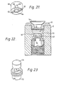
- Figure 21 shows a swirl plate 60 provided with two inlet grooves 62 which tangentially lead into a cylindrical recess 64 passing into a funnel section 66 which, via a short cylindrical section 68, opens on the other side of the plate 60.
- the liquid entering the grooves 62 (of which there may be more than two) passes tangentially into the recess 64 and, via the funnel section 66 and cylindrical sections 68, to the other side of the plate 60, which other side, as can be seen in the assembled nozzle shown in Figure 22, faces the vortex chamber 8.
- the tangential entry via the grooves 62 imparts to the liquid the desired swirling motion which it also retains when in the vortex chamber 8.
- the swirling plate 60 is located immedately below the vortex chamber 8 and held against an abutment 70 by a special set screw 72, shown greatly enlarged in Figure 23.
- This set screw 72 is provided with a bore 74 which, however, does not penetrate its top face 76.
- the upper part of the set screw 72 is of a'reduced diameter and is substantially cylindrical, so that, when screwed home against the swirl plate 60, not only will its top face 76 obturate the entire central section of the swirl plate 60, leaving open and accessible to the liquid only the outer ends of the tangential grooves 62, but, because of the reduced diameter of its upper part, create an annular space 78 ( Figure 22) immediately below the swirl plate 60.
- the set screw 72 and the body 2 could be integral. Furthermore, by providing the set screw 72 (either of the design shown in Figure 22 or of the above described integral design) with, for example, a plurality of radial slots along the upper reduced part of the screw, instead of the two slots shown in Figures 22 and 23, the screw 72 would also function as a filter screeen, keeping out solid particles such as grit or soil particles. These radial slots would have to be deep enough to break into the bore 74, but leave enough of the top face 76 intact to obturate the central section of the swirl plate 60 or its integral analogue.
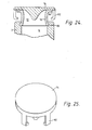
- Figure 24 shows yet another embodiment of a nozzle according to the invention which, from the manufacturing point of view, offers several advantages.
- the nozzle (shown in its non-operative state) has a nozzle body 2, only part of which is shown. Any of the vortex-producing devices described above or otherwise known can be used.
- the orifice sleeve 10 preferably but not necessarily made of a plastics material, is provided at its end facing the vortex chamber 8 with a beaded rim 80 which, upon assembly, is made to snap into an appropriately shaped groove in the nozzle body 2, saving the added expenditure of a- threaded joint.
- the spray-control body 14 which can have any of the shaped described above, is provided with a plurality of hook-like fingers 82 which permit it some radial movement to prevent friction and a few millimeters of axial movement, to let it reach its floating position without the bent ends of the fingers 82 making contact with the underside 84 of the rim of the orifice body 10, but otherwide preventing the spray-control body 14 from sliding or falling off the orifice sleeve 10.
- the retaining rod 16 Figures 1, 3) and its accessories (22-28 in Figure 3) can therefore be dispensed with.
- the fingers 82 can have any cross-section, for example round, oval or rectangular.
- a triangular cross-section, at least of the vertical part of the fingers 82, with the triangle vertex pointing radially inward, would have the effect of reducing the inevitable interference of the fingers with the even spreading of the "sheet" of water. Since the spray-control body 14 rotates as explained above, the retaining fingers 82 having no "shadowing" effect. The fingers 82 could also be used to increase the throw-enhancing rotation of the spray-control body 14. If, for instance, the triangle of the above-mentioned finger cross-section were to be oriented in such a way that it would not be symmetrical with respect to the orifice radius passing through its vertex, a turbine-blade effect would result, assisting the rotary movement of the spray-control body 14.
- Figure 25 is a perspective view of a spray-control body 14 having for example three retaining fingers 82 (of which only two are visible). Whatever their configuration, these fingers 82 must have some degree of elasticity, so that they can be flexed enough to slip over the rim of the orifice sleeve 10, since the ends of the bent portions of these fingers 82 are parts of, or tangent to, a circle the diameter of which is substantially smaller than the diameter of the rim of the outlet of the sleeve 10.
Landscapes
- Nozzles (AREA)
- Acyclic And Carbocyclic Compounds In Medicinal Compositions (AREA)
- Catching Or Destruction (AREA)
Priority Applications (1)
| Application Number | Priority Date | Filing Date | Title |
|---|---|---|---|
| AT79302325T ATE9139T1 (de) | 1978-10-30 | 1979-10-24 | Spritz- oder zerstaeuberduese. |
Applications Claiming Priority (2)
| Application Number | Priority Date | Filing Date | Title |
|---|---|---|---|
| IL55827A IL55827A (en) | 1978-10-30 | 1978-10-30 | Swirl chamber spray-nozzle |
| IL55827 | 1978-10-30 |
Publications (2)
| Publication Number | Publication Date |
|---|---|
| EP0010925A1 EP0010925A1 (en) | 1980-05-14 |
| EP0010925B1 true EP0010925B1 (en) | 1984-08-29 |
Family
ID=11050629
Family Applications (1)
| Application Number | Title | Priority Date | Filing Date |
|---|---|---|---|
| EP79302325A Expired EP0010925B1 (en) | 1978-10-30 | 1979-10-24 | Spray or atomizing nozzle |
Country Status (11)
| Country | Link |
|---|---|
| US (1) | US4331294A (enExample) |
| EP (1) | EP0010925B1 (enExample) |
| JP (1) | JPS5597268A (enExample) |
| AT (1) | ATE9139T1 (enExample) |
| AU (1) | AU528380B2 (enExample) |
| CA (1) | CA1129913A (enExample) |
| DE (1) | DE2967198D1 (enExample) |
| GR (1) | GR73597B (enExample) |
| IL (1) | IL55827A (enExample) |
| MX (1) | MX150082A (enExample) |
| ZA (1) | ZA795503B (enExample) |
Families Citing this family (24)
| Publication number | Priority date | Publication date | Assignee | Title |
|---|---|---|---|---|
| IL61000A0 (en) * | 1980-07-02 | 1980-11-30 | Rottenberg M | Means for repelling mosquitos |
| FR2521876A1 (fr) * | 1982-02-24 | 1983-08-26 | Perales Fernand | Dispositif de support de valve d'emission et de mise en forme du jet, pour installation d'irrigation autonettoyante par giclees |
| US4512519A (en) * | 1982-10-05 | 1985-04-23 | Mifalei Matechet Naan | Sprinkler |
| US4583689A (en) * | 1983-07-22 | 1986-04-22 | Peretz Rosenberg | Rotary sprinkler |
| DE3328467A1 (de) * | 1983-08-06 | 1985-02-21 | Robert Bosch Gmbh, 7000 Stuttgart | Elektromagnetisch betaetigbares ventil |
| DE3464700D1 (en) * | 1983-10-13 | 1987-08-20 | Hozelock Ltd | Lawn sprinkler |
| GB8419286D0 (en) * | 1984-07-27 | 1984-08-30 | Caruana J F | Lawn sprinkler |
| US4986474A (en) * | 1989-08-07 | 1991-01-22 | Nelson Irrigation Corporation | Stream propelled rotary pop-up sprinkler |
| US5058806A (en) * | 1990-01-16 | 1991-10-22 | Nelson Irrigation Corporation | Stream propelled rotary pop-up sprinkler with adjustable sprinkling pattern |
| AU646289B2 (en) * | 1990-09-17 | 1994-02-17 | Leonard Jefferson Blee | Improved sprinkler |
| US5192024A (en) * | 1990-09-17 | 1993-03-09 | Blee Leonard J | Sprinkler |
| US5288022A (en) * | 1991-11-08 | 1994-02-22 | Nelson Irrigation Corporation | Part circle rotator with improved nozzle assembly |
| IL102693A (en) * | 1992-07-31 | 1997-06-10 | Plastro Gvat | Static sprayer including protective cover |
| DK48993D0 (da) * | 1993-04-30 | 1993-04-30 | Steen Erik Holm | Forstoevningsapparat til vandbaaret lungemedicin |
| US5490545A (en) * | 1994-08-31 | 1996-02-13 | Michael D. Sokoloff | Vortex connector |
| FR2739306B1 (fr) * | 1995-10-03 | 1998-05-07 | Lab Sa | Pulverisateur pour liquides charges, notamment de nature abrasive |
| AU2002950802A0 (en) * | 2002-08-15 | 2002-09-12 | Skala, Peter | Fluidic vortex amplifier |
| JP2006111801A (ja) * | 2004-10-18 | 2006-04-27 | Mitsui Eng & Shipbuild Co Ltd | ガスハイドレートスラリー製造装置 |
| US8268354B2 (en) | 2007-11-07 | 2012-09-18 | Aridis Pharmaceuticals | Sonic low pressure spray drying |
| IT1394819B1 (it) * | 2009-07-10 | 2012-07-13 | Drechsel | Regolatore di pressione con massa stabilizzante modulare |
| JP5819142B2 (ja) * | 2011-08-31 | 2015-11-18 | トヨタ紡織株式会社 | 車両用シート |
| US9682386B2 (en) | 2014-07-18 | 2017-06-20 | NaanDanJain Irrigation Ltd. | Irrigation sprinkler |
| US10232388B2 (en) | 2017-03-08 | 2019-03-19 | NaanDanJain Irrigation Ltd. | Multiple orientation rotatable sprinkler |
| KR200495518Y1 (ko) * | 2020-12-22 | 2022-06-13 | 주식회사 서원기술 | 선박용 분무 노즐장치 |
Citations (6)
| Publication number | Priority date | Publication date | Assignee | Title |
|---|---|---|---|---|
| US2116879A (en) * | 1936-08-24 | 1938-05-10 | Thomas R Day | Fog nozzle |
| US2422059A (en) * | 1943-12-14 | 1947-06-10 | Fred B Wilber | Lawn sprinkler |
| FR1010480A (fr) * | 1962-12-19 | 1952-06-11 | Mauser Kg | Procédé et dispositif d'atomisation et de pulvérisation |
| GB812423A (en) * | 1956-02-02 | 1959-04-22 | Film Cooling Towers 1925 Ltd | Improvements in and relating to liquid sprayers |
| FR2288559A1 (fr) * | 1974-10-23 | 1976-05-21 | Rosenberg Peretz | Perfectionnements apportes aux tuyeres d'arrosage |
| DE2753788A1 (de) * | 1976-12-03 | 1978-06-08 | Mitsubishi Precision Co Ltd | Vorrichtung zum zerstaeuben und dispergieren von fluida |
Family Cites Families (13)
| Publication number | Priority date | Publication date | Assignee | Title |
|---|---|---|---|---|
| US599330A (en) * | 1898-02-22 | Fiee extinguished | ||
| US1667943A (en) * | 1922-03-13 | 1928-05-01 | Elmer G Munz | Nozzle |
| US1880880A (en) * | 1930-06-04 | 1932-10-04 | Charles G Dietsch | Nozzle |
| US2247897A (en) * | 1940-03-22 | 1941-07-01 | Spraying Systems Co | Spray nozzle |
| US2639191A (en) * | 1950-04-10 | 1953-05-19 | Jr John O Hruby | Sprinkler head and nozzle |
| US2848276A (en) * | 1956-11-19 | 1958-08-19 | Jack F Clearman | Liquid distributor |
| US2949241A (en) * | 1957-09-23 | 1960-08-16 | Comet Metal Products Co Inc | Lawn and crop sprinkler |
| US3006558A (en) * | 1958-03-19 | 1961-10-31 | Arthur W Jacobs | Lawn sprinkler nozzle |
| US3069099A (en) * | 1960-04-05 | 1962-12-18 | George C Graham | Fuel injection nozzle and spray device |
| US3326473A (en) * | 1964-08-07 | 1967-06-20 | Spraying Systems Co | Spray nozzle |
| US3693886A (en) * | 1971-10-27 | 1972-09-26 | Delavan Manufacturing Co | Swirl air nozzle |
| JPS4871410U (enExample) * | 1971-12-10 | 1973-09-07 | ||
| JPS5176014U (enExample) * | 1974-12-12 | 1976-06-15 |
-
1978
- 1978-10-30 IL IL55827A patent/IL55827A/xx unknown
-
1979
- 1979-10-12 GR GR60251A patent/GR73597B/el unknown
- 1979-10-16 ZA ZA00795503A patent/ZA795503B/xx unknown
- 1979-10-17 AU AU51882/79A patent/AU528380B2/en not_active Ceased
- 1979-10-18 US US06/086,065 patent/US4331294A/en not_active Expired - Lifetime
- 1979-10-24 AT AT79302325T patent/ATE9139T1/de not_active IP Right Cessation
- 1979-10-24 EP EP79302325A patent/EP0010925B1/en not_active Expired
- 1979-10-24 DE DE7979302325T patent/DE2967198D1/de not_active Expired
- 1979-10-29 CA CA338,619A patent/CA1129913A/en not_active Expired
- 1979-10-29 JP JP13884279A patent/JPS5597268A/ja active Granted
- 1979-10-30 MX MX179847A patent/MX150082A/es unknown
Patent Citations (6)
| Publication number | Priority date | Publication date | Assignee | Title |
|---|---|---|---|---|
| US2116879A (en) * | 1936-08-24 | 1938-05-10 | Thomas R Day | Fog nozzle |
| US2422059A (en) * | 1943-12-14 | 1947-06-10 | Fred B Wilber | Lawn sprinkler |
| GB812423A (en) * | 1956-02-02 | 1959-04-22 | Film Cooling Towers 1925 Ltd | Improvements in and relating to liquid sprayers |
| FR1010480A (fr) * | 1962-12-19 | 1952-06-11 | Mauser Kg | Procédé et dispositif d'atomisation et de pulvérisation |
| FR2288559A1 (fr) * | 1974-10-23 | 1976-05-21 | Rosenberg Peretz | Perfectionnements apportes aux tuyeres d'arrosage |
| DE2753788A1 (de) * | 1976-12-03 | 1978-06-08 | Mitsubishi Precision Co Ltd | Vorrichtung zum zerstaeuben und dispergieren von fluida |
Also Published As
| Publication number | Publication date |
|---|---|
| DE2967198D1 (en) | 1984-10-04 |
| ATE9139T1 (de) | 1984-09-15 |
| JPS5597268A (en) | 1980-07-24 |
| ZA795503B (en) | 1981-03-25 |
| IL55827A0 (en) | 1979-01-31 |
| CA1129913A (en) | 1982-08-17 |
| GR73597B (enExample) | 1984-03-26 |
| US4331294A (en) | 1982-05-25 |
| MX150082A (es) | 1984-03-13 |
| EP0010925A1 (en) | 1980-05-14 |
| AU5188279A (en) | 1980-05-15 |
| JPH0253108B2 (enExample) | 1990-11-15 |
| AU528380B2 (en) | 1983-04-28 |
| IL55827A (en) | 1983-02-23 |
Similar Documents
| Publication | Publication Date | Title |
|---|---|---|
| EP0010925B1 (en) | Spray or atomizing nozzle | |
| US4796811A (en) | Sprinkler having a flow rate compensating slow speed rotary distributor | |
| JP2593462B2 (ja) | 回転散水器 | |
| US4261515A (en) | Rotary sprinkler | |
| US5377914A (en) | Speed controlled rotating sprinkler | |
| US6942164B2 (en) | Rotating stream sprinkler with turbine speed governor | |
| EP1508378A2 (en) | Rotating stream sprinkler | |
| US4760958A (en) | Water sprinkler | |
| US3081949A (en) | Water dispersal apparatus | |
| EP0130135B1 (en) | Liquid spraying devices | |
| EP0863803B1 (en) | Rotary sprinkler without dynamic seals | |
| US5192024A (en) | Sprinkler | |
| US4957240A (en) | Rotary sprinklers | |
| EP0212917B1 (en) | Sprinkler device | |
| US4290557A (en) | Sprinklers | |
| CA1168679A (en) | Rotary sprinkler | |
| RU2262991C1 (ru) | Распылитель жидкости турбинного типа | |
| US4783005A (en) | Rotary sprinkler | |
| US20020066801A1 (en) | Fluid atomising device | |
| SU1699630A1 (ru) | Распылитель жидкости | |
| AU645593B2 (en) | Sprinkler | |
| AU674586B2 (en) | Speed controlled rotating sprinkler | |
| SU1498444A1 (ru) | Опрыскиватель | |
| US5415349A (en) | Liquid distribution element | |
| US5984204A (en) | Sprinkler device for dispersing water or other liquid |
Legal Events
| Date | Code | Title | Description |
|---|---|---|---|
| PUAI | Public reference made under article 153(3) epc to a published international application that has entered the european phase |
Free format text: ORIGINAL CODE: 0009012 |
|
| AK | Designated contracting states |
Designated state(s): AT BE CH DE FR GB IT NL |
|
| 17P | Request for examination filed |
Effective date: 19801106 |
|
| ITF | It: translation for a ep patent filed | ||
| GRAA | (expected) grant |
Free format text: ORIGINAL CODE: 0009210 |
|
| AK | Designated contracting states |
Designated state(s): AT BE CH DE FR GB IT NL |
|
| PG25 | Lapsed in a contracting state [announced via postgrant information from national office to epo] |
Ref country code: NL Effective date: 19840829 Ref country code: CH Effective date: 19840829 Ref country code: BE Effective date: 19840829 Ref country code: AT Effective date: 19840829 |
|
| REF | Corresponds to: |
Ref document number: 9139 Country of ref document: AT Date of ref document: 19840915 Kind code of ref document: T |
|
| REF | Corresponds to: |
Ref document number: 2967198 Country of ref document: DE Date of ref document: 19841004 |
|
| ET | Fr: translation filed | ||
| REG | Reference to a national code |
Ref country code: CH Ref legal event code: PL |
|
| NLV1 | Nl: lapsed or annulled due to failure to fulfill the requirements of art. 29p and 29m of the patents act | ||
| PG25 | Lapsed in a contracting state [announced via postgrant information from national office to epo] |
Ref country code: DE Effective date: 19850702 |
|
| PLBE | No opposition filed within time limit |
Free format text: ORIGINAL CODE: 0009261 |
|
| STAA | Information on the status of an ep patent application or granted ep patent |
Free format text: STATUS: NO OPPOSITION FILED WITHIN TIME LIMIT |
|
| 26N | No opposition filed | ||
| REG | Reference to a national code |
Ref country code: FR Ref legal event code: TP |
|
| REG | Reference to a national code |
Ref country code: GB Ref legal event code: 732 |
|
| ITPR | It: changes in ownership of a european patent |
Owner name: CESSIONE;PLASTRO - GUAT S.R.L. |
|
| ITTA | It: last paid annual fee | ||
| PGFP | Annual fee paid to national office [announced via postgrant information from national office to epo] |
Ref country code: GB Payment date: 19971015 Year of fee payment: 19 |
|
| PG25 | Lapsed in a contracting state [announced via postgrant information from national office to epo] |
Ref country code: GB Free format text: LAPSE BECAUSE OF NON-PAYMENT OF DUE FEES Effective date: 19981024 |
|
| PGFP | Annual fee paid to national office [announced via postgrant information from national office to epo] |
Ref country code: FR Payment date: 19981030 Year of fee payment: 20 |
|
| GBPC | Gb: european patent ceased through non-payment of renewal fee |
Effective date: 19981024 |