BACKGROUND OF THE INVENTION
-
This invention relates generally to improvements in irrigation
sprinklers of the so-called micro-stream type having a rotatably driven vaned
deflector for sweeping a plurality of relatively small water streams over a
surrounding terrain area to irrigate adjacent vegetation. More specifically, this
invention relates to an improved rotating stream sprinkler having a ball drive rotor
for rotatably driving the deflector in a succession of relatively small angular
increments or steps, in combination with a speed control brake for maintaining
the rotational speed of the vaned deflector substantially constant throughout a
range of normal operating pressures and flow rates.
-
Rotating stream sprinklers, sometimes referred to as micro-stream
sprinklers, are well known in the art of the type for producing a plurality of
relatively small outwardly projected water streams swept over surrounding
terrain. In one common form, one or more jets of water are directed upwardly
against a rotatable vaned deflector which has a vaned lower surface defining an
array of relatively small flow channels extending upwardly and turning radially
outwardly with a spiral component of direction. The water jet or jets impinge
upon this underside vaned deflector surface to fill these curved flow channels
and to rotatably drive the deflector. At the same time, the water is guided by the
curved flow channels for projection generally radially outwardly from the sprinkler
in the form of a plurality of relatively small water streams to irrigate adjacent
vegetation. As the deflector is rotatably driven, these water streams are swept
over the surrounding terrain area, with a range of throw depending in part on the
channel configuration. Such rotating stream sprinklers have been designed for
irrigating a surrounding terrain area of predetermined pattern, such as a full
circle, half-circle, or quarter-circle pattern. For examples of such rotating stream
sprinklers, see U.S. Patents 4,660,766; 4,796,811; 4,815,662; 4,971,250;
4,986,474; Re. 33,823; 5,288,022; 5,058,806; 5,845,849; and 6,244,521.
-
In rotating stream sprinklers of this general type, it is desirable to
control or regulate the rotational speed of the vaned deflector and thereby also
regulate the speed at which the water streams are swept over the surrounding
terrain area. In this regard, in the absence of speed control or brake means, the
vaned deflector can be rotatably driven at an excessive speed up to and
exceeding 1,000 rpm, resulting in rapid sprinkler wear and distorted waterstream
delivery patterns. A relatively slow deflector rotational speed on the order of
about 4-20 rpm is desired to achieve extended sprinkler service life while
producing uniform and consistent water stream delivery patterns. Toward this
end, a variety of fluid brake devices have been developed wherein a rotor
element carried by the vaned deflector is rotatably driven within a closed
chamber containing a viscous fluid. In such designs, the viscous fluid applies a
substantial drag to rotor element rotation which significantly reduces the
rotational speed of the vaned deflector during sprinkler operation.
-
While such fluid brake devices are effective to prevent deflector
rotation at excessive speeds, the actual rotational speed of the deflector
inherently and significantly varies as a function of changes in water pressure and
flow rate through the sprinkler. Unfortunately, these parameters can vary during
any given period or cycle of sprinkler operation, resulting in corresponding
variations in the water stream delivery patterns for irrigating the surrounding
vegetation. In addition, such fluid brake concepts require the use and effective
sealed containment of a viscous fluid such as a silicon-based oil or the like,
which undesirably increases the overall complexity and cost of the irrigation
sprinkler.
-
Copending U.S. Serial No. 10/310,584, filed December 4, 2002,
discloses an improved rotating stream sprinkler having a nonfluid speed control
brake for maintaining the rotational speed of the vaned deflector substantially
constant throughout a range of normal operating pressures and flow rates. A
resilient brake pad is mounted between a friction plate rotatable with the
deflector and a nonrotating brake disk, with one or more of these components
incorporating a suitably tapered contact surface designed for varying the
frictional resistance to deflector rotation in a manner achieving substantially
constant rotational speed during normal operating conditions. While this
improved sprinkler design beneficially avoids the problems and disadvantages
associated with prior fluid brake concepts, the deflector is continuously rotated
to sweep the water streams over the surrounding terrain to be irrigated. Such
continuous rotation of the deflector inherently reduces the range of throw of the
outwardly projected water streams.
-
There exists, therefore, a need for further improvements in and to
rotating stream sprinklers of the type for sweeping a plurality of relatively small
water streams over a surrounding terrain area, particularly with respect to
maximizing the range of the outwardly projected water streams while at the same
time maintaining the rotational speed of a vaned deflector at a controlled,
relatively slow, and substantially constant rate. The present invention fulfills
these needs and provides further related advantages.
SUMMARY OF THE INVENTION
-
In accordance with the invention, a rotating stream sprinkler is
provided of the type having a rotatable vaned deflector for sweeping a plurality
of relatively small water streams over a surrounding terrain area to irrigate
adjacent vegetation. The sprinkler includes a turbine driven ball drive rotor
having at least one drive ball carried by centrifugal force into repetitious impact
engagement with one or more raised anvils on the deflector for incrementally
displacing the deflector in a succession of small rotational steps. The sprinkler
further includes a speed control brake for providing a variable friction force
resisting deflector rotation, to maintain deflector rotation substantially constant
within a range of normal water supply pressures and flow rates.
-
The rotating stream sprinkler comprises the vaned deflector
rotatably mounted above a sprinkler base and having an underside surface
defined by an array of vanes with generally vertically oriented upstream ends
which curve and merge smoothly with generally radially outwardly extending
downstream ends. These vanes cooperatively define a corresponding array of
intervening, relatively small flow channels of corresponding configuration. One
or more water jets, directed upwardly through jet ports formed in a pattern plate
on the sprinkler base, impinge upon these deflector vanes and are subdivided
into a plurality of relatively small water streams flowing through said flow
channels for projection radially outwardly from the sprinkler to irrigate the
surrounding terrain area. The specific pattern of irrigated terrain area is
determined by the pattern of jet ports formed in the pattern plate to provide, for
example, a substantially full circle, half-circle, or quarter-circle irrigation pattern.
-
The ball drive rotor includes at least one and preferably multiple
drive balls carried within radially outwardly open slotted tracks, with the drive
balls supported on a radially outwardly inclined ramp defined on an upper
surface of the deflector. A turbine is rotatably driven by a swirling water flow
passed through an array of angularly oriented swirl ports formed in a swirl plate,
and the turbine in turn rotatably drives the rotor at a speed sufficient to displace
the drive balls radially outwardly within their respective slotted tracks and
upwardly on the inclined ramp by centrifugal action. The drive balls are thus
displaced by centrifugal force into impact engagement with one or more anvils
protruding radially inwardly from an upstanding, generally cylindrical wall on the
deflector at the periphery of the inclined ramp.
-
Impact engagement between one of the drive balls and one of the
anvils on the deflector wall causes the deflector to rotate through a relatively
small angular step or increment, whereupon the deflector ceases rotation for a
brief interval until the next impact engagement between a drive ball and anvil.
During this brief interval, the water streams are projected outwardly from the
stationary deflector with a maximum radius of throw. In addition, the drive ball
is impact-displaced radially inwardly a sufficient distance to permit continued
turbine driven rotation of the ball drive rotor, followed by return movement of the
drive ball in a radially outward direction by centrifugal action for subsequent
impact engagement with the same or a different one of the anvils on the
deflector. Thus, the drive balls are carried by centrifugal force for impact
engagement with the drive anvils in a rapid and repetitious succession to
correspondingly rotate the deflector through a rapid succession of small
rotational steps.
-
The speed control brake, in the preferred form, includes a brake pad
interposed axially between an upwardly presented friction surface on the
deflector and a nonrotating brake disk. Upon supply of water through the pattern
plate jet ports to impinge upon the deflector vanes, the deflector is urged axially
upwardly to compress the brake pad between the deflector friction surface and
the brake disk, thereby generating frictional resistance to deflector rotation. The
speed control brake is preferably designed in accordance with copending U.S.
Serial No. 10/310,584, filed December 4, 2002, which is incorporated by
reference herein, to provide a variable frictional resistance to maintain deflector
rotational speed substantially constant within a range of normal water supply
pressures and flow rates.
-
Other features and advantages of the present invention will become
more apparent from the following detailed description taken in conjunction with
the accompanying drawings which illustrate, by way of example, the principles
of the invention.
BRIEF DESCRIPTION OF THE DRAWINGS
-
The accompanying drawings illustrate the invention. In such
drawings:
- FIGURE 1 is a fragmented perspective view illustrating a rotating
stream sprinkler of the present invention installed onto the upper end of a riser;
- FIGURE 2 is a side elevation view of the rotating stream sprinkler
viewed in FIG. 1, shown in exploded relation with the riser depicted in partial
section;
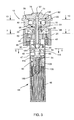
- FIGURE 3 is an enlarged vertical sectional view taken generally on
the line 3-3 of FIG. 1;
- FIGURE 4 is an exploded perspective view of the rotating stream
sprinkler;
- FIGURE 5 is a horizontal sectional view taken generally on the line
5-5 of FIG. 3;
- FIGURE 6 is an enlarged fragmented side elevation view taken
generally on the line 6-6 of FIG. 5, with portions broken away to illustrate
construction details of an internally mounted swirl plate;
- FIGURE 7 is a horizontal sectional view taken generally on the line
7-7 of FIG. 3;
- FIGURE 8 is an underside perspective view of a vaned deflector;
- FIGURE 9 is a side elevation view of the vaned deflector of FIG. 8;
- FIGURE 10 is a vertical sectional view taken generally on the line
10-10 of FIG. 9;
- FIGURE 11 is a top plan view of the vaned deflector, taken generally
on the line 11-11 of FIG. 9;
- FIGURE 12 is an underside perspective view of a ball drive rotor
forming a portion of a ball drive arrangement for the rotating stream sprinkler;
- FIGURE 13 is an enlarged horizontal sectional view taken generally
on the line 13-13 of FIG. 3;
- FIGURE 14 is a fragmented horizontal sectional view, similar to a
portion of FIG. 13, and illustrating impact engagement of a drive ball with a
radially inwardly protruding anvil on the vaned deflector;
- FIGURE 15 is an enlarged and exploded perspective view showing
components of an adjustable flow control assembly for the sprinkler; and
- FIGURE 16 is an enlarged sectional view similar to FIG. 3, but
depicting adjustment of the flow control assembly.
-
DETAILED DESCRIPTION OF THE PREFERRED EMBODIMENT
-
As shown in the exemplary drawings, a rotating stream sprinkler
referred to generally in FIGURES 1-4 by the reference numeral 10 includes a
vaned deflector 12 for producing and distributing a plurality of relatively small
water streams 14 (FIG. 1) projected radially outwardly therefrom to irrigate a
surrounding terrain area. The deflector 12 is rotatably indexed in a rapid
succession of relatively small angular steps or increments by a turbine driven ball
drive rotor 16 (FIGS. 3, 4 and 12-14) including one or more drive balls 18 for
repetitious impact engagement with one or more anvils 20 carried by the
deflector. A speed control brake 22 (FIG. 3) is additionally provided to maintain
the rotational speed of the deflector 12 at a controlled, relatively slow, and
substantially constant speed throughout a range of normal operating pressures
and flow rates.
-
The rotating stream sprinkler 10 of the present invention generally
comprises a compact sprinkler nozzle unit or head having a base 24 adapted for
convenient thread-on mounting or the like onto the upper end of a stationary or
pop-up tubular riser 26 (FIGS. 1-2). The deflector 12 is rotatably supported on
the base 24 and includes an underside surface defining an array of vanes 28
(FIGS. 1-4, 8 and 9) for projection of the plurality of relatively small water
streams 14 (FIG. 1) radially outwardly from the deflector 12 to irrigate
surrounding vegetation. The ball drive rotor 16 is rotatably driven by a turbine
30 (FIG. 3) for carrying the drive ball or balls 18 by centrifugal action into
repeated impact engagement with the anvil or anvils 20 (FIGS. 3, 10 and 11) to
rotatably drive the deflector in a succession of small rotational steps, thereby
sweeping the outwardly projected water streams 14 in a stepwise fashion over
the surrounding terrain. The speed control brake 22 provides a variable frictional
resistance to deflector rotation for purposes of maintaining deflector rotational
speed at a relatively slow and substantially constant rate of about 4-20 rpm,
throughout a normal range of water supply pressures and flow rates.
Accordingly, the improved sprinkler 10 beneficially provides a consistent and
uniform pattern of water distribution during each operating cycle, with deflector
rotation momentarily halting after each rotational step to permit the projected
water streams 14 to achieve a substantially maximized range of throw.
-
More particularly, as shown in FIGS. 1-4 in accordance with one
preferred form of the invention, the sprinkler base 24 has a generally cylindrical
shape with an internal female thread 32 (FIG. 3) formed within a lower region
thereof for convenient and simple mounting of the base 24 onto an externally
threaded upper end 34 (FIG. 2) of the tubular riser 26. An internal, radially
inwardly projecting annular rib 36 (FIG. 3) is formed within the base 24 to define
a downwardly presented annular shoulder for seated support and retention of a
circular pattern plate 40 which may be attached to the base 24 as by means of
a suitable adhesive, or by a weld process such as ultrasonic welding.
Alternatively, the pattern plate 40 may be formed integrally with the base 24, as
by plastic injection molding or the like. As viewed best in FIG. 7, the pattern
plate 40 has an array of upwardly open jet ports 42 formed therein in an annular
pattern, with the illustrative drawings showing four elongated arcuate ports 42
each spanning an arcuate range of slightly less than 90° for substantially full-circle
distribution of water from the sprinkler during operation, as will be
described in more detail. Persons skilled in the art will recognize and appreciate
that the number and geometry of these jet ports 42 can be varied for selected
part-circle water distribution, such as a quarter-circle, half-circle, or other
selected part-circle irrigation pattern.
-
A filter unit 44 having an upwardly open and generally cup-shaped
configuration is mounted at the underside of the sprinkler base 24. In one form,
this filter unit includes an outwardly radiating upper flange 48 having a size and
shape for press-fit or snap-fit reception into the underside of the base 24, with
a generally cylindrical side wall suspended therefrom. In an alternative form, the
filter unit 44 may be configured for slide-fit reception into the open upper end of
the riser 26, with the flange 48 rested upon the riser upper end, prior to thread-on
mounting of the base 24. In either configuration, the cylindrical side wall of
the filter unit 44 is slidably received into the riser upper end and has a perforated
lower segment 46. This perforated lower segment 46 of the filter unit 44 is
sufficiently spaced from an internal diameter surface of the riser 26 so that water
inflow to the sprinkler 10 may pass through the perforations which obstruct
passage of sizable particulate and other debris which could other damage
sprinkler components.
-
The turbine 30 is mounted at a lower end of a drive shaft 50
extending downwardly through a central aperture 52 formed in the pattern plate
40. This drive shaft 50 is rotatably carried within a tubular bearing sleeve 54, a
lower end of which extends downwardly through the pattern plate 40 and is
captured by a shaft seal 56. The turbine 30 is mounted onto the drive shaft 50
as by press-fit or snap-fit mounting thereon, to position the turbine within an
upper region of the filter unit 44 in the path of upward water flow to the sprinkler
10, when the riser 26 is connected to a supply of water under pressure. A swirl
plate 58 is positioned within a substantially imperforate upper segment 47 of the
cylindrical side wall of the filter unit 44, at an upstream location relative to the
turbine 30, and includes an annular array of angularly oriented swirl ports 60
(shown best in FIGS. 5-6) for imparting a circumferential swirl flow to water inflow
passing through the riser 26 to the sprinkler 10 to rotatably drive the turbine 30
and the associated drive shaft 50. As shown, the swirl plate 58 may include a
peripheral ridge 62 (FIG. 6) for snap-fit mounting into a matingly shaped internal
groove 64 formed within the imperforate upper segment 47 of the filter unit 44.
-
The drive shaft 50 and the associated bearing sleeve 54 project
upwardly from the pattern plate 40 for rotatably supporting the deflector 12, and
for rotatably driving the ball drive rotor 16 on the same axis but independently of
deflector rotation. More specifically, the bearing sleeve 54 extends upwardly
through a central hub 66 of the deflector 12, and supports this deflector hub 66
in an axial position sandwiched between a lower seal member 68 and a radially
enlarged thrust flange 70 at the upper end of the bearing sleeve 54. With this
arrangement, the deflector 12 is supported on the exterior of the bearing sleeve
54 for rotation relative to said bearing sleeve, whereas the drive shaft 50 is
supported within the bearing sleeve 54 for rotation relative to said bearing
sleeve. The bearing sleeve 54 is supported by secure, nonrotational connection
to the pattern plate 40.
-
The deflector 12, which may be conveniently formed from lightweight
molded plastic, incorporates the array of vanes 28 formed on an underside
surface thereof. This array of vanes is disposed, as previously described, for
engagement by the jet or jets of water flowing upwardly from the pattern plate
40, in accordance with the number and configuration of jet ports 42 formed in the
pattern plate. These vanes 28 (shown best in FIGS. 8-9) are shown to have a
generally V-shaped cross section defining a corresponding plurality of
intervening flow channels of inverted generally V-shaped cross section extending
upwardly and then curving smoothly to extend generally radially outwardly with
a selected inclination angle. In the preferred form, these vanes 28 and the
associated flow channels do not incorporate any significant spiral or helical
component of direction. In operation of the sprinkler, the upwardly directed
water jet or jets from the pattern plate 40 impinge upon the lower or upstream
segments of these vanes 28 which subdivide the water flow into the plurality
relatively small flow streams 14 for passage through the flow channels and
radially outward projection from the sprinkler. With the pattern plate jet ports 42
arranged in a substantially full-circle array as shown (FIG. 7), the resultant water
jets impinge upon the array of deflector vanes 28 for substantially full-circle
distribution of water streams 14 from the sprinkler. Alternative jet port
arrangements in the pattern plate 40, such as quarter-circle or half-circle
arrangements (not shown) will produce a corresponding part-circle impingement
of water upon the deflector vanes 28 for part-circle distribution of water streams
14 from the sprinkler. By forming the vanes 28 and the associated flow channels
without a significant spiral or helical configuration, the water jet or jets impinging
on the vanes do not impart any significant rotary drive torque to the deflector 12.
-
The ball drive rotor 16 may also be formed from molded plastic or
the like and is mounted onto an upper end of the drive shaft 50 for rotation
therewith at an upper surface of the deflector 12. FIGS. 12-14 show the ball
drive rotor 16 in one preferred form to include a generally disk-shaped element
having a central hub 72 secured as by press-fit or snap-fit mounting onto an
upper segment of the drive shaft 50 for rotatable driving therewith, with an upper
end of the drive shaft being axially slidably and rotatably positioned within a
central recess 74 (FIG. 3) formed at the underside of a cap plate 76. The cap
plate 76 is in turn seated at its periphery as by press-fit or snap-fit seated
reception into a shallow counterbore 78 formed at the upper margin of a
generally cylindrical wall 80 upstanding from the periphery of the deflector upper
surface and the periphery of the underside vane array 28. As shown best in FIG.
3, the upper side of the deflector 12 cooperates with the deflector wall 80 and
the cap plate 76 to define a substantially enclosed drive chamber 82 within which
the drive rotor 16 is positioned.
-
The drive rotor 16 includes at least one and preferably a plurality of
radially outwardly open slotted tracks 84, with four of said slotted tracks 84 being
shown in FIGS. 12-13 formed at substantially equiangular intervals. At least one
and preferably multiple drive balls 18 are rollably carried within these tracks 84
for centrifugal displacement in response to rotatable driving of the drive rotor 16.
In this regard, each drive ball 18 has a substantial mass, as by forming the drive
balls from steel or stainless steel or the like. In addition, the perimeter of the
drive rotor 16 is radially spaced from the deflector wall 80 by a clearance
sufficient to accommodate free rotor rotation relative to the deflector, but such
clearance is insufficient to permit escape of the drive ball 18 from its associated
track 84. Similarly, the vertical dimension of the drive chamber 82 is also
insufficient to permit drive ball escape from the associated track 84. In the
illustrative drawings (FIG. 13), two drive balls 18 are positioned respectively
within a diametrically opposed pair of the slotted tracks 84, to provide a balanced
rotary structure. Persons skilled in the art will appreciate, however, that any
number of drive balls 18 and a corresponding number of slotted tracks 84 may
be used, with a preferred arrangement including multiple drive balls arranged in
a balanced array about the rotational axis of the drive shaft 50.
-
The upper surface of the deflector 12, within the drive chamber 82,
includes an inclined ramp 86 extending radially outwardly and axially upwardly
from the central deflector hub 66 toward the peripheral wall 80. Each drive ball
18 is rollingly supported on this inclined ramp 86, whereby each drive ball 18
normally rolls down this ramp in a radially inward direction along the associated
slotted track 84 when the rotor 16 is stationary. However, upon rotational driving
of the rotor 16 at a speed capable of generating a sufficient centrifugal force,
each drive ball 18 is displaced by centrifugal action in a radially outward direction
along the associated track 84.
-
When this occurs, each drive ball 18 moves into rolling contact
against an interior surface of the deflector wall 80. In accordance with one
aspect of the invention, the wall surface incorporates at least one and preferably
multiple radially inwardly protruding anvils 20. As the rotor 16 is driven at a
sufficient speed, the drive balls 18 are thus rotationally carried into impact
engagement with the anvils 20, with the resultant impact force being effective to
rotate the deflector 12 through a small rotary step or increment of a few degrees.
Following such impact, the drive ball 18 is displaced radially inwardly a sufficient
distance to clear the impacted anvil 20 by the combined effect of ball rebound
and interrupted rotor speed to produce insufficient centrifugal force to maintain
each drive ball 18 in the radially outermost position. As a result, the step-rotated
deflector 12 momentarily ceases rotation and remains stationary for a brief
interval until resumed rotor rotation again carries a drive ball 18 by centrifugal
action to the radially outermost position for impact engagement with an anvil 20.
The drive ball or balls 18 repeated and rapidly strike the anvil or anvils 20 at a
regular impact frequency for rotatably driving the deflector 12 in a rapid
succession of small rotational steps, thereby sweeping the projected water
streams 14 over the surrounding terrain area in a similar rapid succession of
small rotational steps.
-
The speed control brake 22 comprises a relatively simple yet highly
effective structure for frictionally resisting rotational displacement of the deflector
12, thereby assuring step-wise rotation in relatively small increments of
substantially uniform angular displacement. As shown, the speed control brake
22 comprises an annular brake pad 88 formed from a suitable brake material
such as a resilient silicone-based elastomer or the like interposed axially
between the deflector hub 66 and the thrust flange 70 on the bearing sleeve 54.
In this regard, the deflector hub 66 defines an axially upwardly presented friction
surface 89 (shown best in FIG. 16) rotatable with the deflector 12, whereas the
thrust flange 70 defines an axially downwardly presented brake disk carried by
the bearing sleeve 54 and thereby constrained against rotation.
-
When water under pressure is supplied to the sprinkler, the upwardly
directed jet or jets impinging upon the vanes 28 provide a thrust force urging the
deflector 12 axially upwardly through a short stroke to compress the brake pad
88 between the deflector hub 66 and the thrust flange 70 (as viewed in FIG. 3).
The magnitude of this upward thrust force varies in direct proportion to variations
in water supply pressure and/or water flow rate. In this regard, in the most
preferred form, the contact surfaces of the brake pad 88 with the friction surface
89 (FIGS. 10, 11 and 16) on the deflector hub 66 and the axially underside
surface of the thrust flange 70 are shaped for variably adjusting the surface
contact radius in response to fluctuations in water supply pressure and/or flow
rate which can occur in the course of any given cycle of sprinkler operation, to
achieve a substantially constant speed of deflector rotation despite such
pressure and/or flow rate fluctuations within a normal operating range. In this
regard, the brake pad 88 preferably includes a tapered profile for varying the
radius of surface contact to correspondingly vary the friction brake torque
substantially as a linear function of changes in water pressure and flow rate.
This brake pad geometry, and functional alternatives, is shown and described
in copending U.S. Serial No. 10/310,584, filed December 4, 2002, which is
incorporated by reference herein.
-
The specific design parameters of the sprinkler components can be
selected to achieve a target and substantially constant deflector rotational speed
within a desired and relatively slow speed range on the order of about 4-20 rpm.
In this regard, the turbine 30 can be designed in conjunction with the ball drive
rotor 16 and associated drive balls 18 for rotatably driving the rotor at a relatively
high rate of speed, such as about 350-400 rpm. The angle of the inclined ramp
86 on the deflector 12 can be selected in relation to ball mass to achieve radially
outward ball displacement by centrifugal force when rotor rotation exceeds a
predetermined speed, such as about 325-350 rpm. By selecting the number of
drive balls 18 and associated number of anvils 20, a target frequency of ball-anvil
impact engagement can be obtained, such as about 360 impacts per
minute. Finally, by appropriately designing the speed control brake 20 to provide
a predetermined frictional resistance to deflector rotation, the angular increment
of each deflector step can be obtained, such as about 4° per step increment to
yield a deflector rotational speed of about 4 rpm. With this arrangement, the
deflector 12 is rotatably driven in a rapid succession of step-wise increments, the
deflector rotation being briefly interrupted after each rotational step for a time
period sufficient for the outwardly projected water streams 14 to achieve a
substantially maximized projected range.
-
A flow rate adjustment assembly 90 (FIGS. 3-4 and 15-16) may be
provided for selectively setting the water flow rate through the sprinkler 10, for
purposes of regulating the range of throw of the projected water streams 14. As
shown, this flow rate adjustment assembly 90 is mounted within the filter unit 44
at an upstream location relative to the swirl plate 58. Conveniently, the flow rate
adjustment assembly 90 is adapted for variable setting by means of a
screwdriver 91 (FIG. 16) or the like engageable with a screwdriver slot 92 or the
like formed in an upwardly exposed surface of the cap plate 76 (FIGS. 3 and 16).
-
The illustrative flow rate adjustment assembly 90 includes an
adjustment screw 94 having a head 96 rotatably carried and axially retained by
a cylindrical hub 98 of the swirl plate 58. A threaded screw shank 100 is
suspended from the head 96 to project downwardly into the interior of the filter
unit 44, in an upstream direction extending away from the swirl plate 58. A flow
rate adjustment nut 102 is threaded carried on the shank 100 and includes at
least one and preferably multiple radially outwardly extending wings 104 (FIG.
15) engages with internal ribs or splines 106 (FIG. 16) formed within the
perforated lower side wall segment 46. Accordingly, rotation of the screw head
96 and associate shank 100 is accompanied by axial translation of the flow rate
adjustment nut 102, without nut rotation on the screw.
-
A resilient flow rate restrictor element 108 is captured between the
flow rate adjustment nut 102 and a support disk 110 seated axially against a
backstop flange 112 formed on the screw head 96 (FIGS. 3 and 16). In addition,
this support disk 110 may also include a pair of outwardly radiating ears 114
(shown best in FIG. 15) for snap-fit reception into a corresponding pair of side
ports 116 (FIGS. 2-3) formed in the imperforate upper side wall segment 47 of
the filter unit 44. As shown, the support disk 110 includes a downwardly
protruding nose 111 (FIG. 4) of noncircular geometry for seated reception into
a matingly shaped noncircular seat 109 (FIG. 15) formed in an upper side of the
restrictor element 108 to rotationally align and retain these components with
respect to each other. Importantly, the restrictor element 108 includes a plurality
of peripheral flow channels or slots 118 (FIGS. 15-16) which are respectively
aligned axially with a corresponding plurality of peripheral flow channels or slots
120 formed in the support disk 110. These aligned flow channels 118, 120
accommodate upward waterflow past the flow rate adjustment assembly 90 and
further to the swirl plate 58 for normal sprinkler operation.
-
However, the flow rate of water through these channels 118, 120
can be selectively throttled or reduced by rotating the adjustment screw 94 in a
direction translating the adjustment nut 102 in an upward direction to compress
the restrictor element 108. Such adjustment is illustrated in FIG. 16 which shows
a conically tapered upper surface 122 on the nut 102 bearing against a matingly
tapered lower surface 123 on the restrictor element 108, to cause a side wall of
the restrictor element 108 to bulge radially outwardly as indicated by arrows 124,
resulting in restriction of the cross sectional areas of the flow channels 118 and
a corresponding restriction or reduction in water flow rate past the adjustment
assembly 90.
-
The head 96 of the adjustment screw 94 includes an upwardly
presented slotted recess 125 (FIG. 5) which is normally positioned in axially
spaced relation below the turbine 30. That is, upon normal supply of water
under pressure to the sprinkler, upwardly directly water flow acts against the
turbine 30 and the vaned underside surface of the deflector 12 to urge the
turbine 30 and deflector 12 together with the drive shaft 50 upwardly through a
short axial stroke to a normal first position with the speed control brake
components are axially engaged. In this normal operating position, as viewed
in FIG. 3, a lower end of the drive shaft 50 including a tool member, e.g., a
slotted tool tip 126 such as a Phillips-type screwdriver tip, is axially spaced
above the swirl plate 58 to permit unimpeded rotation of the drive shaft 50 and
components mounted thereon.
-
However, when the screwdriver 91 or other suitable tool is engages
with the cap plate slot 92 and pressed downwardly, as depicted by arrow 128 in
FIG. 16, the cap plate 76 is translated axially downwardly through a short stroke
into engagement with an upper side of the ball drive rotor 16. Importantly, the
underside surface of the cap plate 76 includes one or more downwardly
protruding keys 130 (FIGS. 3, 4 and 16) for engaging the axially upwardly open
and matingly shaped keyways 132 (FIGS. 3, 12-14 and 16) formed in the hub 72
of the ball drive rotor 16. At the same time, continued downward pressure
applied to the cap plate 76 shifts the deflector 12 downwardly to disengage the
speed control brake components (FIG. 16) and also shifts the drive shaft 50
downwardly a sufficient distance to engage the tool tip 126 with the tool recess
125 formed in the head 96 of the flow rate adjustment screw 94.
-
In this downwardly shifted orsecond position, subsequent rotational
movement of the screwdriver 91 will impart a corresponding rotational motion via
the rotor 16 to the drive shaft 50 and the associated tool tip 126 thereon, for
rotatably adjusting the position of the flow rate adjustment screw 94, thereby
variably altering the water flow rate to and through the sprinkler 10. When a
desired adjustment setting is reached, the tool 91 is removed and subsequent
resumption of water supply under pressure to the sprinkler automatically shifts
the turbine 30 and the deflector 12 with the drive shaft 50 upwardly within the
bearing sleeve 54 to disengage the cap plate keys 130 from the keyways 132 on
the ball drive rotor 16, and also to disengage the drive shaft tool tip 126 from the
flow rate adjustment screw 94. At the same time, this upward water pressure
acting on the deflector 12 returns the components of the speed control brake into
engagement for resumed speed control function.
-
With this arrangement, the specific water flow rate to and through
the sprinkler 10 can be quickly and easily set. Thereafter, water under pressure
supplied via the riser 26 flows through the swirl plate 58 for rotatably driving the
turbine 30, which in turn rotatably drives the rotor 16 and associated drive ball
or balls 18. As the water flow continues upwardly through the pattern plate 40
to impinge upon the deflector vanes 28, for outward projection in the form of the
relatively small water streams 14, the drive ball or balls 18 repetitiously impact
the anvil or anvils 20 for rotatably driving the deflector 12 is a succession of
small rotary steps. As a result, the streams 14 are swept in a stepwise fashion
over the surrounding terrain. The speed control brake 22 advantageously
maintains the rotational speed of the deflector 12 at a relatively slow and
substantially constant flow rate throughout a normal range of water supply
pressures and flow rates, to achieve highly uniform and consistent distribution
of irrigation water.
-
A variety of further modifications and improvements in and to the
rotating stream sprinkler of the present invention will be apparent to those
persons skilled in the art. Accordingly, no limitation on the invention is intended
by way of the foregoing description and accompanying drawings, except as set
forth in the appended claims.