EP0010562B1 - Procédé d'électrolyse - Google Patents
Procédé d'électrolyse Download PDFInfo
- Publication number
- EP0010562B1 EP0010562B1 EP19780400147 EP78400147A EP0010562B1 EP 0010562 B1 EP0010562 B1 EP 0010562B1 EP 19780400147 EP19780400147 EP 19780400147 EP 78400147 A EP78400147 A EP 78400147A EP 0010562 B1 EP0010562 B1 EP 0010562B1
- Authority
- EP
- European Patent Office
- Prior art keywords
- electrolysis
- fixed electrodes
- fact
- electrodes
- per
- Prior art date
- Legal status (The legal status is an assumption and is not a legal conclusion. Google has not performed a legal analysis and makes no representation as to the accuracy of the status listed.)
- Expired
Links
- 238000000034 method Methods 0.000 title claims description 25
- 230000008569 process Effects 0.000 title claims description 18
- 238000005868 electrolysis reaction Methods 0.000 claims description 23
- 150000001875 compounds Chemical class 0.000 claims description 10
- 238000006243 chemical reaction Methods 0.000 claims description 9
- 239000003792 electrolyte Substances 0.000 claims description 9
- 239000002245 particle Substances 0.000 claims description 7
- 230000003647 oxidation Effects 0.000 claims description 6
- 238000007254 oxidation reaction Methods 0.000 claims description 6
- 239000008151 electrolyte solution Substances 0.000 claims description 4
- 230000009467 reduction Effects 0.000 claims description 4
- 239000000243 solution Substances 0.000 claims description 4
- 238000003475 lamination Methods 0.000 claims 1
- 238000005516 engineering process Methods 0.000 description 4
- 238000006722 reduction reaction Methods 0.000 description 4
- 238000003487 electrochemical reaction Methods 0.000 description 3
- 230000008030 elimination Effects 0.000 description 3
- 238000003379 elimination reaction Methods 0.000 description 3
- 238000009434 installation Methods 0.000 description 3
- 239000000047 product Substances 0.000 description 3
- 239000000725 suspension Substances 0.000 description 3
- 238000003786 synthesis reaction Methods 0.000 description 3
- 231100000331 toxic Toxicity 0.000 description 3
- 230000002588 toxic effect Effects 0.000 description 3
- OKTJSMMVPCPJKN-UHFFFAOYSA-N Carbon Chemical compound [C] OKTJSMMVPCPJKN-UHFFFAOYSA-N 0.000 description 2
- 230000015572 biosynthetic process Effects 0.000 description 2
- 238000010586 diagram Methods 0.000 description 2
- 239000003344 environmental pollutant Substances 0.000 description 2
- 238000012423 maintenance Methods 0.000 description 2
- 238000004519 manufacturing process Methods 0.000 description 2
- 231100000719 pollutant Toxicity 0.000 description 2
- 230000004888 barrier function Effects 0.000 description 1
- 238000010349 cathodic reaction Methods 0.000 description 1
- 239000007795 chemical reaction product Substances 0.000 description 1
- 239000003153 chemical reaction reagent Substances 0.000 description 1
- 239000000470 constituent Substances 0.000 description 1
- 230000006378 damage Effects 0.000 description 1
- 238000007599 discharging Methods 0.000 description 1
- 230000000694 effects Effects 0.000 description 1
- 239000003295 industrial effluent Substances 0.000 description 1
- 239000003456 ion exchange resin Substances 0.000 description 1
- 229920003303 ion-exchange polymer Polymers 0.000 description 1
- 150000002500 ions Chemical class 0.000 description 1
- 230000005012 migration Effects 0.000 description 1
- 238000013508 migration Methods 0.000 description 1
- 230000001590 oxidative effect Effects 0.000 description 1
- 238000011084 recovery Methods 0.000 description 1
- 230000002468 redox effect Effects 0.000 description 1
- 238000006479 redox reaction Methods 0.000 description 1
- 230000001603 reducing effect Effects 0.000 description 1
- 230000001105 regulatory effect Effects 0.000 description 1
- 230000004044 response Effects 0.000 description 1
- 238000000926 separation method Methods 0.000 description 1
- 239000000126 substance Substances 0.000 description 1
- 230000009466 transformation Effects 0.000 description 1
Images
Classifications
-
- C—CHEMISTRY; METALLURGY
- C25—ELECTROLYTIC OR ELECTROPHORETIC PROCESSES; APPARATUS THEREFOR
- C25B—ELECTROLYTIC OR ELECTROPHORETIC PROCESSES FOR THE PRODUCTION OF COMPOUNDS OR NON-METALS; APPARATUS THEREFOR
- C25B9/00—Cells or assemblies of cells; Constructional parts of cells; Assemblies of constructional parts, e.g. electrode-diaphragm assemblies; Process-related cell features
-
- C—CHEMISTRY; METALLURGY
- C02—TREATMENT OF WATER, WASTE WATER, SEWAGE, OR SLUDGE
- C02F—TREATMENT OF WATER, WASTE WATER, SEWAGE, OR SLUDGE
- C02F1/00—Treatment of water, waste water, or sewage
- C02F1/46—Treatment of water, waste water, or sewage by electrochemical methods
- C02F1/461—Treatment of water, waste water, or sewage by electrochemical methods by electrolysis
- C02F1/46104—Devices therefor; Their operating or servicing
- C02F1/46109—Electrodes
-
- C—CHEMISTRY; METALLURGY
- C02—TREATMENT OF WATER, WASTE WATER, SEWAGE, OR SLUDGE
- C02F—TREATMENT OF WATER, WASTE WATER, SEWAGE, OR SLUDGE
- C02F1/00—Treatment of water, waste water, or sewage
- C02F1/001—Processes for the treatment of water whereby the filtration technique is of importance
-
- C—CHEMISTRY; METALLURGY
- C02—TREATMENT OF WATER, WASTE WATER, SEWAGE, OR SLUDGE
- C02F—TREATMENT OF WATER, WASTE WATER, SEWAGE, OR SLUDGE
- C02F1/00—Treatment of water, waste water, or sewage
- C02F1/46—Treatment of water, waste water, or sewage by electrochemical methods
- C02F1/461—Treatment of water, waste water, or sewage by electrochemical methods by electrolysis
- C02F1/46104—Devices therefor; Their operating or servicing
- C02F1/46109—Electrodes
- C02F1/46114—Electrodes in particulate form or with conductive and/or non conductive particles between them
-
- C—CHEMISTRY; METALLURGY
- C02—TREATMENT OF WATER, WASTE WATER, SEWAGE, OR SLUDGE
- C02F—TREATMENT OF WATER, WASTE WATER, SEWAGE, OR SLUDGE
- C02F1/00—Treatment of water, waste water, or sewage
- C02F1/46—Treatment of water, waste water, or sewage by electrochemical methods
- C02F1/461—Treatment of water, waste water, or sewage by electrochemical methods by electrolysis
- C02F1/46104—Devices therefor; Their operating or servicing
- C02F1/46109—Electrodes
- C02F2001/46152—Electrodes characterised by the shape or form
Definitions
- the invention relates to electrolytic cells.
- the presence of a separator between the anode and cathode compartments has been made unnecessary. It is highlighted that the porous separator, contrary to what shows the current practice, can be advantageously eliminated, which authorizes the circulation of an electrode dispersed in the whole of the electrolytic cell, and makes it possible to eliminate the disadvantages which result from the presence of a separator.
- the dispersed electrode is formed by a suspension in the electrolyte of conductive particles.
- Various arrangements of all the elements of the cell are proposed and in particular as regards the circulation of the dispersed electrode with respect to the fixed electrodes.
- Such a method can be used for any electrolytic cell, in general for all oxidation or reduction reactions and in particular for synthesis reactions, or of destruction or elimination of toxic or polluting compounds contained in the effluents.
- the invention relates to techniques which use electrochemical reactions. It relates more precisely to the design of a process and an electrolysis cell for the implementation of redox reactions. It is likely to receive applications as varied as are the many uses of electrochemical reactions, in various industries. However, reference will be made more particularly in the following to two preferred types of applications of the assembly according to the invention, which are the electrolysers intended for the transformation of the basic products of an electrochemical synthesis, and those used for the elimination of toxic or polluting compounds contained in effluents.
- the present invention relates to an electrolysis method and device, resulting from the observation made that the reverse reactions occurring at the electrodes of each polarity, often take place at different kinetics, this being generally applicable to all oxidation or reduction reactions and authorizing the removal of compartmentalization of the cell.
- Such a separator has a number of drawbacks; in particular, and by virtue of its mere presence, the separator causes an ohmic drop between the electrodes, all the more important as the electrolyser operates at higher current densities.
- the invention aims to overcome these drawbacks by eliminating the porous diaphragm.
- the removal of the separator allows the use of a dispersed electrode circulating in the whole of the electrolyte and through the fixed electrodes, and which can consequently be in contact with both the cathode and the anode. fixed.
- the polarity of the dispersed electrode is determined by the direction of the reaction with the fastest kinetics.
- the purpose of such a dispersed electrode is to improve the yields of the operation.
- the method of the invention applies to all cases where each of the constituents in solution is characterized by redox properties, such that one of the two reactions, oxidation or reduction, occurs with kinetics faster than l 'other.
- the electrolytic solution can be brought into contact simultaneously with the positive electrodes and the negative electrodes without there being any fear that the reactions which occur at the electrodes of a polarite will be annihilated by those occurring at the reverse polarity electrodes.
- only one reaction is able to occur with appreciable kinetics. This effect could advantageously be amplified, possibly, by the judicious choice of the relative surfaces of the electrodes of opposite polarities.
- Such a process is likely to be used in a particularly advantageous manner, either in the context of electrosynthesis operations, or for the treatment of effluents.
- the present invention allows, in the case of its application to the treatment of effluents, to overcome these drawbacks by installing the device of the invention which it is possible to adapt directly to the circuit for discharging pollutant discharges.
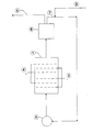
- the single figure proposes a diagram of nonlimiting application of the method of the invention to the treatment of effluents.
- the electrolytic cell is directly supplied by the effluent evacuation circuit at 2.
- the cathodes and anodes 3 and 4 may especially, as in the case of an electrolytic cell intended for electrochemical synthesis operations, including be arranged transversely to the passage of the effluent, in which case the fixed electrodes must be crossed by the suspension; the fixed electrodes can, in this case, present themselves under various aspects and in particular: plates pierced with holes through which the compulsory migration of the suspension takes place; grids crossed in the same way; a network of wires or strips, tubes or plates.
- the purified effluent leaves the device at 5, after passing through a filter 6 which can in particular be a rotary filter, which allows the recovery of the particles of the electrode dispersed at 7 with a view to their reuse; their reintroduction into the circuit is regulated by means of a pump 8.
- a filter 6 which can in particular be a rotary filter, which allows the recovery of the particles of the electrode dispersed at 7 with a view to their reuse; their reintroduction into the circuit is regulated by means of a pump 8.
- the invention is not limited to the particular embodiments which have been described by way of example. In particular, it extends to the application of any other method making it possible to carry out an electrolysis reaction in the absence of a separator between the anode and cathode compartments.
- the invention is not limited to the examples which have just been given, but embraces all the variants thereof.
Landscapes
- Chemical & Material Sciences (AREA)
- Organic Chemistry (AREA)
- Electrochemistry (AREA)
- Engineering & Computer Science (AREA)
- Chemical Kinetics & Catalysis (AREA)
- General Chemical & Material Sciences (AREA)
- Life Sciences & Earth Sciences (AREA)
- Hydrology & Water Resources (AREA)
- Environmental & Geological Engineering (AREA)
- Water Supply & Treatment (AREA)
- Materials Engineering (AREA)
- Metallurgy (AREA)
- Electrolytic Production Of Non-Metals, Compounds, Apparatuses Therefor (AREA)
- Water Treatment By Electricity Or Magnetism (AREA)
Description
- L'invention concerne des cellules électrolytiques.
- Conformément à l'invention, la présence d'un séparateur entre les compartiments anodiques et cathodiques a été rendue inutile. Il est mis en évidence que le séparateur poreux, contrairement à ce que montre la pratique courante, peut être avantageusement supprimé, ce qui autorise la circulation d'une électrode dispersée dans l'ensemble de la cellule électrolytique, et permet de supprimer les inconvénients qui résultent de la présence d'un séparateur.
- L'électrode dispersée est formée par une suspension, dans l'électrolyte, de particules conductrices. Diverses dispositions de l'ensemble des éléments de la cellule sont proposées et notamment en ce qui concerne la circulation de l'électrode dispersée par rapport aux électrodes fixes.
- Un tel procédé est utilisable pour toute cellule électrolytique, d'une manière générale pour toutes réactions d'oxydation ou de réduction et en particulier pour des réactions de synthèse, ou de destruction ou élimination de composés toxiques ou polluants contenus dans les effluents.
- L'invention concerne les techniques qui mettent en oeuvre des réactions étectro- chimiques. Elle concerne plus précisément la conception d'un procédé et d'une cellule d'électrolyse pour la mise en oeuvre des réactions d'oxydo-réduction. Elle est susceptible de recevoir des applications aussi variées que le sont les nombreux usages des réactions électrochimiques, dans des industries diverses. Cependant, on se référera plus particulièrement dans ce qui suit à deux types d'applications privilégiées de l'ensemble selon l'invention que constituent les électrolyseurs destinés à la transformation des produits de base d'une synthèse électrochimique, et ceux utilisés pour l'élimination de composés toxiques ou polluants contenus dans les effluents.
- La présente invention concerne un procédé et un dispositif d'électrolyse, résultant de l'observation faite que les réactions inverses se produisant au niveau des électrodes de chaque polarité, s'effectuent souvent à des cinétiques différentes, ceci étant applicable d'une manière générale à toutes réactions d'oxydation ou de réduction et autorisant la suppression du compartimentage de la cellule.
- Jusqu'à présent, le souci d'éviter que celle des deux réactions inverses que l'on ne désire pas voir se produire n'anihile celle qui est recherchée, a conduit à séparer les électrodes par un diaphragme qui compartimente le bain électrolytique. Il est de pratique courante que les opérations d'électrolyse s'effectuent dans les électrolyseurs divisés en deux ou plusieurs compartiments, contenant respectivement chacune des électrodes de polarités opposées baignant dans un électrolyte, par un séparateur qui doit être à la fois suffisamment poreux pour être perméable aux ions qui assurent le passage du courant électrique d'un compartiment à l'autre, mais cependant capable d'opposer une barrière efficace aux réactifs ou produits des réactions électrochimiques formés dans chaque compartiment.
- Cependant, un tel séparateur présente un certain nombre d'inconvénients; en particulier, et du fait de sa seule présence, le séparateur provoque une chute ohmique entre les électrodes, d'autant plus importante que l'électrolyseur fonctionne à de plus fortes densités de courant. L'invention a pour objectif de pallier ces inconvénients par la suppression du diaphragme poreux.
- Selon l'invention la suppression du séparateur autorise l'utilisation d'une électrode dispersée circulant dans l'ensemble de l'électrolyte et a travers les électrodes fixes, et pouvant par conséquent se trouver au contact tant de la cathode que de l'anode fixes. La polarité de l'électrode dispersée est déterminée par le sens de la réaction dont la cinétique est la plus rapide.
- La présence d'un telle électrode dispersée à pour objet d'améliorer les rendements de l'opération.
- Le procédé de l'invention s'applique à tous les cas où chacun des constituants en solution se caractérise par des propriétés d'oxydoréduction, telles que l'une des deux réactions, oxydation ou réduction, se produit avec une cinétique plus rapide que l'autre. En pareil cas, la solution électrolytique peut être mise en contact simultanément avec les électrodes positives et les électrodes négatives sans pour autant qu'il y ait à craindre que les réactions qui se produisent aux électrodes d'une polarite soient anihilées par celles se produisant aux électrodes de polarité inverse. Pour chacun des composés à transformer ou à éliminer, une seule réaction (soit une oxydation à l'électrode positive, soit une réduction à l'électrode négative) est en mesure de se produire avec une cinétique appréciable. Cet effet pourra être avantageusement amplifié, éventuellement, par le choix judicieux des surfaces relatives des électrodes de polarités opposées.
- Un tel procédé est de nature à être utilisé de façon particulièrement avantageuse, soit dans le cadre d'opérations d'électrosynthèse, soit pour le traitement d'effluents.
- Sa mise en oeuvre, ne nécessite pas l'interposition, entre les électrodes, de séparateur interdisant aux produits réactionnels cathodiques d'entrer en contact avec l'anode, et par suite et inversement, le procédé proposé conduit à une simplification de conception et de fonctionnement des cellules d'électrolyse. Ceci les rend, notamment, particulièrement aptes au traitement des effluents industriels dans leur circuit même d'évacuation.
- On s'attachera, à titre d'exemple non limitatif d'application du procédé de l'invention à mettre en évidence les avantages de celui-ci par rapport aux méthodes et dispositifs habituels de traitement d'effluent, et à en décrire un schéma de principe n'ayant aucun caractère restrictif.
- Dans la pratique habituelle, le traitement des effluents nécessite soit une élimination physique des composés toxiques ou polluants, soit leur transformation chimique de façon à les rendre inoffensifs.
- Dans le premier cas il est fait appel soit à des résines échangeuses d'ions, soit à du charbon actif.
- Dans le second cas, on utilise des produits chimiques à effet oxydant ou réducteur, destinées à transformer les polluants en corps facilement récupérables et séparables.
- Ces deux types de traitement présentent un certain nombre d'inconvénients parmi lesquels:
- - un prix de revient élevé du fait de l'utilisation de produits coûteux et d'importantes installations;
- - la nécessité d'une maintenance permanente des installations par un personnel compétent;
- - une réponse toujours imparfaite au problème de fonctionnement en continu;
- - un rendement énergétique faible;
- - une durée de traitement susceptible de provoquer un ralentissement du rythme de fonctionnement de l'unité de production.
- La présente invention permet, dans le cas de son application au traitement des effluents, de pallier ces inconvénients par l'installation du dispositif de l'invention qu'il est possible d'adapter directement sur le circuit d'évacuation des rejets polluants.
- La figure unique propose un schéma d'application non limitative du procédé de l'invention au traitement des effluents.
- La cuve d'électrolyse est directement alimentée par le circuit d'évacuation des effluents en 2. Les cathodes et anodes 3 et 4 peuvent notamment, comme d'ailleurs dans le cas d'une cuve électrolytique destinée à des opérations de synthèse électrochimique, y être disposés de façon transversale au passage de l'effluent, au quel cas les électrodes fixes doivent être franchies par la suspension; les électrodes fixes peuvent, dans ce cas, se présenter sous divers aspects et notamment: des plaques percées de trous par lesquels s'effectue la migration obligatoire de la suspension; des grilles traversées de la même manière; un réseau de fils ou lamelles, tubes ou plaques. L'effluent purifié quitte le dispositif en 5, après passage à travers un filtre 6 pouvant être notamment un filtre rotatif, qui permet le récupération des particules de l'électrode dispersée en 7 en vue de leur réutilisation; leur réintroduction dans le circuit est réglée au moyen d'une pompe 8.
- Tel qu'il est conçu et décrit, le procédé d'électrolyse qui fait l'objet du présent brevet se distingue donc fondamentalement des trois procédés connus par ses caractéristiques de principe, de mise en oeuvre et de fonctionnement:
- l'électrolyse réalisée au moyen de seules électrodes fixes sans présence d'électrode sous forme de particules;
- -la technologie de l'électrode en lit fluidisé;
- -la technologie de l'électrode en lit compacté ou lit fixe.
- Ces deux derniers procédés, bien que faisant appel à une forme d'électrode en particules, interdisent la libre circulation de celle-ci dans l'ensemble du circuit, les particules étant caractérisées par leur faible conductivité, leur bipolarité et donc une résistance suffisante pour éviter tout court-circuit entre les électrodes fixes.
- Naturellement, et comme il résulte d'ailleurs très largement de ce qui précède, l'invention n'est pas limitée aux modes de réalisation particuliers qui ont été décrits à titre d'exemple. En particulier, elle s'étend à l'application de tout autre procédé permettant de réaliser une réaction d'électrolyse en l'absence de séparateur entre les compartiments anodiques et cathodiques.
- En définitive, l'invention ne se limite pas aux exemples qui viennent d'être donnés, mais en embrasse toutes les variantes.
Claims (10)
Priority Applications (2)
| Application Number | Priority Date | Filing Date | Title |
|---|---|---|---|
| DE7878400147T DE2862460D1 (en) | 1978-10-25 | 1978-10-25 | Electrochemical process |
| EP19780400147 EP0010562B1 (fr) | 1978-10-25 | 1978-10-25 | Procédé d'électrolyse |
Applications Claiming Priority (1)
| Application Number | Priority Date | Filing Date | Title |
|---|---|---|---|
| EP19780400147 EP0010562B1 (fr) | 1978-10-25 | 1978-10-25 | Procédé d'électrolyse |
Publications (2)
| Publication Number | Publication Date |
|---|---|
| EP0010562A1 EP0010562A1 (fr) | 1980-05-14 |
| EP0010562B1 true EP0010562B1 (fr) | 1985-02-13 |
Family
ID=8186044
Family Applications (1)
| Application Number | Title | Priority Date | Filing Date |
|---|---|---|---|
| EP19780400147 Expired EP0010562B1 (fr) | 1978-10-25 | 1978-10-25 | Procédé d'électrolyse |
Country Status (2)
| Country | Link |
|---|---|
| EP (1) | EP0010562B1 (fr) |
| DE (1) | DE2862460D1 (fr) |
Families Citing this family (6)
| Publication number | Priority date | Publication date | Assignee | Title |
|---|---|---|---|---|
| DE3069071D1 (en) * | 1979-10-23 | 1984-10-04 | Creconsult Ltd | A process for the electrochemical degradation of persistent organic compounds, with harmful or potentially harmful properties |
| NL8006412A (nl) * | 1980-11-25 | 1982-06-16 | Tno | Werkwijze voor het detoxificeren van chemische afvalstoffen. |
| US4399020A (en) * | 1981-07-24 | 1983-08-16 | Diamond Shamrock Corporation | Device for waste water treatment |
| EP0322478A1 (fr) * | 1987-12-30 | 1989-07-05 | Kay Wilms | Procédé et dispositif pour le traitement de l'eau par l'oxydation anodique, spécialement pour la production d'eau potable stérile |
| FR2717459B1 (fr) * | 1994-03-16 | 1996-04-12 | Commissariat Energie Atomique | Procédé et installation de destruction de solutes organiques, en particulier d'agents complexants, présents dans une solution aqueuse telle qu'un effluent radioactif. |
| AU2007200853B1 (en) * | 2006-11-13 | 2007-07-26 | Newtreat Pty Ltd | Electroflocculation |
Family Cites Families (6)
| Publication number | Priority date | Publication date | Assignee | Title |
|---|---|---|---|---|
| US3288692A (en) * | 1962-09-20 | 1966-11-29 | Pullman Inc | Electrochemical process for the production of organic oxides |
| US3616356A (en) * | 1967-09-18 | 1971-10-26 | Clarence H Roy | Electrolysis in a particulate carbon packing |
| US4310406A (en) * | 1968-10-01 | 1982-01-12 | Resource Control, Incorporated | Apparatus for removing metal ions and other pollutants from aqueous solutions and moist gaseous streams |
| US4004994A (en) * | 1972-07-12 | 1977-01-25 | Stauffer Chemical Company | Electrochemical removal of contaminants |
| DE2460754C2 (de) * | 1974-12-21 | 1982-07-15 | Hoechst Ag, 6000 Frankfurt | Verfahren zur Herstellung von p-Benzochinondiketalen |
| FR2375351A1 (en) * | 1976-12-21 | 1978-07-21 | Inst Neorganicheskoi Khim | Electrolysis system for oxidation reactions - using extended surface electrode formed by conducting particles in cell |
-
1978
- 1978-10-25 EP EP19780400147 patent/EP0010562B1/fr not_active Expired
- 1978-10-25 DE DE7878400147T patent/DE2862460D1/de not_active Expired
Also Published As
| Publication number | Publication date |
|---|---|
| EP0010562A1 (fr) | 1980-05-14 |
| DE2862460D1 (en) | 1985-03-28 |
Similar Documents
| Publication | Publication Date | Title |
|---|---|---|
| EP0031267B1 (fr) | Electrode poreuse percolante fibreuse modifiée en carbone ou graphite et son application à la réalisation de réactions électrochimiques | |
| EP1671711A1 (fr) | Procede de purification de matiere contaminee par des metaux lourds et appareil destine a cet effet | |
| CN106660837A (zh) | 用于进行电芬顿反应以分解有机化合物的装置 | |
| FR2555913A1 (fr) | Procede de desionisation electrochimique de solutions aqueuses | |
| CN110240221A (zh) | 一种光电催化体系及降解有机污染物同时回收贵金属银的方法 | |
| EP4039655B1 (fr) | Réacteur permettant la filtration en continu d'un fluide en écoulement à travers d'un filtre et avec une régénération électrochimique in situ du filtre | |
| FR2755789A1 (fr) | Procede et appareil de traitement d'une solution de dechets radioactifs | |
| RU145009U1 (ru) | Микробный топливный элемент и схема сборки таких элементов | |
| EP0010562B1 (fr) | Procédé d'électrolyse | |
| CN108658177A (zh) | 一种适用于水中难降解有机物去除的电化学活性炭纤维毡膜反应器 | |
| CN114538572B (zh) | 利用电化学水处理装置处理反渗透浓水的方法 | |
| EP0141780A1 (fr) | Procédé pour la décontamination électrochimique de l'eau | |
| US7704373B2 (en) | Waste fluid or waste water treatment method and its apparatus | |
| JP5812874B2 (ja) | 微生物燃料電池システム | |
| Liu et al. | Electrified carbon nanotube membrane technology for water treatment | |
| EP0449735B1 (fr) | Réacteur de dépollution électrolytique | |
| WO2012168447A1 (fr) | Procédé de traitement par percolation d'un élément de feutre par électrodéposition | |
| FR2993902A1 (fr) | Cellule d'electrolyse | |
| EP0756582A1 (fr) | Destruction des complexes cyano metalliques par la combinaison d'oxydation chimique et d'electrolyse | |
| FR2573221A1 (fr) | Procede et dispositif pour la recuperation de l'argent des bains de fixage | |
| FR3077008A1 (fr) | Procede et dispositif de capture et/ou de liberation d'especes anioniques assiste par electrolyse | |
| EP0534029A1 (fr) | Installation électrochimique et procédé de traitement d'effluents aqueux contenant un métal lourd | |
| FR2927326A1 (fr) | Procede et equipement pour l'oxydation de matieres organiques | |
| FR2681079A1 (fr) | Dispositif et procede d'electrolyse a electrode poreuse et agitee. | |
| EP1031633A1 (fr) | Cellule électrochimique de type filtre-presse destinée à la lixiviation de pulpes contenant des métaux valables |
Legal Events
| Date | Code | Title | Description |
|---|---|---|---|
| PUAI | Public reference made under article 153(3) epc to a published international application that has entered the european phase |
Free format text: ORIGINAL CODE: 0009012 |
|
| AK | Designated contracting states |
Designated state(s): BE CH DE GB |
|
| 17P | Request for examination filed |
Effective date: 19810728 |
|
| RAP1 | Party data changed (applicant data changed or rights of an application transferred) |
Owner name: SORAPEC SOCIETE DE RECHERCHES ET D'APPLICATIONS EL |
|
| GRAA | (expected) grant |
Free format text: ORIGINAL CODE: 0009210 |
|
| AK | Designated contracting states |
Designated state(s): BE CH DE GB |
|
| REF | Corresponds to: |
Ref document number: 2862460 Country of ref document: DE Date of ref document: 19850328 |
|
| PLBE | No opposition filed within time limit |
Free format text: ORIGINAL CODE: 0009261 |
|
| STAA | Information on the status of an ep patent application or granted ep patent |
Free format text: STATUS: NO OPPOSITION FILED WITHIN TIME LIMIT |
|
| 26N | No opposition filed | ||
| PGFP | Annual fee paid to national office [announced via postgrant information from national office to epo] |
Ref country code: BE Payment date: 19931006 Year of fee payment: 16 |
|
| PGFP | Annual fee paid to national office [announced via postgrant information from national office to epo] |
Ref country code: GB Payment date: 19931019 Year of fee payment: 16 |
|
| PGFP | Annual fee paid to national office [announced via postgrant information from national office to epo] |
Ref country code: CH Payment date: 19931028 Year of fee payment: 16 |
|
| PGFP | Annual fee paid to national office [announced via postgrant information from national office to epo] |
Ref country code: DE Payment date: 19931210 Year of fee payment: 16 |
|
| PG25 | Lapsed in a contracting state [announced via postgrant information from national office to epo] |
Ref country code: GB Effective date: 19941025 |
|
| PG25 | Lapsed in a contracting state [announced via postgrant information from national office to epo] |
Ref country code: CH Effective date: 19941031 Ref country code: BE Effective date: 19941031 |
|
| BERE | Be: lapsed |
Owner name: SORAPEC SOC. DE RECHERCHERS ET D'APPLICATION ELEC Effective date: 19941031 |
|
| GBPC | Gb: european patent ceased through non-payment of renewal fee |
Effective date: 19941025 |
|
| REG | Reference to a national code |
Ref country code: CH Ref legal event code: PL |
|
| PG25 | Lapsed in a contracting state [announced via postgrant information from national office to epo] |
Ref country code: DE Effective date: 19950701 |