EP0010557A1 - Dispositif pour assurer le transport d'un mélange en suspension de vase et d'eau venaut d'être dragué - Google Patents
Dispositif pour assurer le transport d'un mélange en suspension de vase et d'eau venaut d'être dragué Download PDFInfo
- Publication number
- EP0010557A1 EP0010557A1 EP78200287A EP78200287A EP0010557A1 EP 0010557 A1 EP0010557 A1 EP 0010557A1 EP 78200287 A EP78200287 A EP 78200287A EP 78200287 A EP78200287 A EP 78200287A EP 0010557 A1 EP0010557 A1 EP 0010557A1
- Authority
- EP
- European Patent Office
- Prior art keywords
- pressure
- closing member
- pump
- duct
- suction
- Prior art date
- Legal status (The legal status is an assumption and is not a legal conclusion. Google has not performed a legal analysis and makes no representation as to the accuracy of the status listed.)
- Granted
Links
- XLYOFNOQVPJJNP-UHFFFAOYSA-N water Substances O XLYOFNOQVPJJNP-UHFFFAOYSA-N 0.000 title claims abstract description 20
- 239000000725 suspension Substances 0.000 title description 3
- 238000000034 method Methods 0.000 claims abstract description 8
- 239000012530 fluid Substances 0.000 claims abstract description 7
- 230000001502 supplementing effect Effects 0.000 claims abstract description 4
- 239000000654 additive Substances 0.000 claims description 3
- 230000000996 additive effect Effects 0.000 claims description 3
- 230000009469 supplementation Effects 0.000 claims description 3
- 239000000463 material Substances 0.000 abstract description 4
- 239000012528 membrane Substances 0.000 description 3
- 239000006096 absorbing agent Substances 0.000 description 1
- 230000002238 attenuated effect Effects 0.000 description 1
- 230000005540 biological transmission Effects 0.000 description 1
- 238000013016 damping Methods 0.000 description 1
- 239000000203 mixture Substances 0.000 description 1
- 210000002445 nipple Anatomy 0.000 description 1
- 238000005086 pumping Methods 0.000 description 1
- 238000007789 sealing Methods 0.000 description 1
- 239000013589 supplement Substances 0.000 description 1
Images

Classifications
-
- E—FIXED CONSTRUCTIONS
- E02—HYDRAULIC ENGINEERING; FOUNDATIONS; SOIL SHIFTING
- E02F—DREDGING; SOIL-SHIFTING
- E02F3/00—Dredgers; Soil-shifting machines
- E02F3/04—Dredgers; Soil-shifting machines mechanically-driven
- E02F3/88—Dredgers; Soil-shifting machines mechanically-driven with arrangements acting by a sucking or forcing effect, e.g. suction dredgers
- E02F3/90—Component parts, e.g. arrangement or adaptation of pumps
- E02F3/907—Measuring or control devices, e.g. control units, detection means or sensors
-
- E—FIXED CONSTRUCTIONS
- E02—HYDRAULIC ENGINEERING; FOUNDATIONS; SOIL SHIFTING
- E02F—DREDGING; SOIL-SHIFTING
- E02F3/00—Dredgers; Soil-shifting machines
- E02F3/04—Dredgers; Soil-shifting machines mechanically-driven
- E02F3/88—Dredgers; Soil-shifting machines mechanically-driven with arrangements acting by a sucking or forcing effect, e.g. suction dredgers
- E02F3/90—Component parts, e.g. arrangement or adaptation of pumps
- E02F3/902—Component parts, e.g. arrangement or adaptation of pumps for modifying the concentration of the dredged material, e.g. relief valves preventing the clogging of the suction pipe
-
- F—MECHANICAL ENGINEERING; LIGHTING; HEATING; WEAPONS; BLASTING
- F04—POSITIVE - DISPLACEMENT MACHINES FOR LIQUIDS; PUMPS FOR LIQUIDS OR ELASTIC FLUIDS
- F04D—NON-POSITIVE-DISPLACEMENT PUMPS
- F04D15/00—Control, e.g. regulation, of pumps, pumping installations or systems
- F04D15/0005—Control, e.g. regulation, of pumps, pumping installations or systems by using valves
- F04D15/0016—Control, e.g. regulation, of pumps, pumping installations or systems by using valves mixing-reversing- or deviation valves
Definitions
- the invention relates to a method of safeguarding fluid transport through a hydraulic transport duct including a pump, in which at a pressure drop below a predetermined pressure on the suction side of the pump, through a balanced closing member moved into the open position by a source of power water is supplemented into the transport duct and at an excess pressure above said predetermined pressure the supplementation is terminated.
- the invention has for its object to safeguard on the one hand the fluid transport and on the other hand to maintain as much and as long as possible the suction power in the suction duct in order to introduce much material to be transported and little water into the transport duct. According to the invention this is achieved by counteracting the source of power in. order to move the closing member into the closed position by a pressure admitted into a pressure chamber and prevailing on the suction side of the pump and by enlarging or reducing the passage of the closing member according as the pressure on the suction side of the pump becomes lower or higher respectively.
- the movements of the closing member are preferably damped.
- the invention relates to and provides a device for carrying out the method according to the invention, said device comprising a hydraulic transport duct particularly forming part of a dredging device and consisting mainly of a pump, a pressure duct and a suction duct having a suction nozzle, a closing member included in the suction duct near the pump and compelled into the open position by the action of a source of power for supplementing water into the suction duct and comprising driving means controlled by the pressure on the suction side of the pump for moving the closing member into the closed position against the source of power.
- This device is characterized in that the suction duct communicates with a pressure chamber bounded by a movable wall subjected to a source of power counteracting the pressure in the pressure chamber and being mechanically coupled with the closing member.
- a particularly well balanced closing member is formed by a cylindrical slide.
- the source of power preferably comprises a pneumatic spring.
- the device according to the invention preferably comprises an additive, hydraulic motor for closing the closing member.
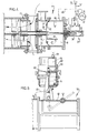
- the ground dredger 1 of Figure 1 comprises a vessel 5 and a hydraulic transport duct 2 suspended thereto for sucking up ground from a bottom 4- below the water 3.
- This transport duct 2 mainly consists of a pump 10, a pressure duct 39 and a suction duct 9 and a closing member 14.
- the transport duct 2 comprises two rigid lengths of tubing 6 of the suction duct 9 and a rigid length of tubing 16 of the pressure duct 39, which are pivoted to one another by means of hinges 12 about pivotal axes 7 and by means of a hinge 13 about a pivotal axis 8 to the vessel 5.
- the suction duct 9 has a nozzle 11 to be inserted into the bottom 4, through which a suspension of ground and water is sucked into the transport duct 2.
- the tubings 6 and 16 communicate with one another at the area of the hinges 12 through bellows 15.
- the pump 10 together with the upper tubing 16 is rigidly secured to a frame 27, which is suspended to the vessel 5 so as to be pivotable about an axis 8.
- the upper tubing 16 communicates through bellows 28 with a pump 53 positioned in the vessel 5 for pumping on the suspension through a duct 41.
- the frame 27 and the rigid tubings 16 are furthermore suspended to the vessel 5 by means of cables 29 of hoisting devices 30 positioned on the vessel 5.
- the closing member 14 is included in the suction duct 9 near the pump 10 and the closing part 17 of said member is compelled under the action of a source of power, for example, a spring, preferably a pneumatic spring 18, into an open position for supplementing water 3 into the suction duct 9.
- a source of power for example, a spring, preferably a pneumatic spring 18, into an open position for supplementing water 3 into the suction duct 9.
- This pneumatic spring 18 consists of a pressure chamber 19 bounded by a movable wall 20 having a membrane 21 and communicating through an inlet 22 with a wind kettle 23 havig a predetermined absolute pressure of, for example, 2 metres water column.
- the movable wall 20 bounds on the other side a pressure chamber 24, which communicates through an inlet 25 and a connecting duct 26 near the pump 10 with the suction duct 9 for absorbing the pressure prevailing there.
- the movable wall 20 is mechanically coupled with the closing part 17 of the closing member 14.
- the closing part 17 is preferably formed by a cylindrical slide 31, which is axially displaceable in bearings 32 and 33 and which can shut an annular inlet gap 34 to a controlled extent.
- control member 14 is closed, in which position the closing part 17 is in sealing relationship with a radial, stationary wall 36 by means of a rubber seal 35.
- the closing part 17 is balanced by its shape and bearing position so that it can be closed or opened by comparatively little power. Use is made of an equilibrium between the pressure on the suction side of the pump 10 and a predetermined pressure in the wind kettle 23, in which case the difference in pressure provides directly, that is to say without transmission ratio the required power for opening and closing respectively.
- the closing member 14 is moved into the open position at a drop below the pressure on the suction side of the pump 10, that is to say, at a drop below the predetermined pressure in the pressure chamber 19 so that water 3 is supplemented into the transport duct 2.
- the supplementation is stopped. In this manner such a state of equilibrium of the closing part 17 is attained that exactly the amount of water 3 is supplemented which is required by the operational conditions.
- the passage of the closing member 14 is enlarged and reduced according as the pressure on the suction side of the pump 10 becomes lower and higher respectively. In order to avoid a rapid reciprocatory movement of the wall 20, this movement is preferably attenuated by means of a piston 36 of a hydraulic absorber 37 fastened to the wall 20.
- the pressure chamber 24 has a small opening 54,. through which a small amount of water 3 continuously trickles in so that the pressure chamber 24 and the connecting duct 26 are flushed to cleanness.
- the damper 37 communicates through chokes 38 with the oil chamber 44 of a pressure compensator 42 having a membrane 43, which separates the oil chamber 44 from an air chamber 45.
- the air chamber 45 communicates through a duct 46 with the pressure chamber 19 in order to have low pressure in the air chamber 45.
- the extreme positions of the closing part 17 can be observed with the aid of electric tell-tale switches 47 and 48 actuated by stops 49 and 50 respectively of the wall 20 for remote-signalling of said positions.
- the closing member 14 If in the event of a calamity, for example, a torn membrane 21 the closing member 14 remains in the open position, it can be closed from a distance with the aid of a manual oil pump 51, which upon actuation automatically closes a flap 52 in the overflow damping circuit of the damper 37 and which energizes the damper 37 in the closing direction of the closing part 17.
- the damper 37 thus constitutes an additive motor for closing the closing part 17.
- the opening 54 which is larger in Figure 4 than in Figure 3, is provided with a flap 55 remote--controlled from the vessel 5 in order to flush the chamber 24 from time to time.
- the closing member 56 is formed by a butterfly flap 58 pivoting about a shaft 57 and being actuated by a piston 59 of a cylinder 60, which in itself is pivotable with respect to the suction duct 9 about a hinge 62.
- the piston 59 is a moving wall between the pressure chamber 24 and a presssure chamber 19 operating as a pneumatic spring, in which through a nipple 61 a predetermined pressure of, for example, 1,5 water column is produced.
- the pressure chamber 24 again communicates through a connecting duct 26 with the suction duct 9 so that at a pressure drop below the predetermined pressure in the suction duct 9 the butterfly valve 58 is moved into the controlled, preferably narrowly opened position.
- Figure 5 shows the extreme open position.
Landscapes
- Engineering & Computer Science (AREA)
- Mechanical Engineering (AREA)
- General Engineering & Computer Science (AREA)
- Mining & Mineral Resources (AREA)
- Civil Engineering (AREA)
- Structural Engineering (AREA)
- Structures Of Non-Positive Displacement Pumps (AREA)
Priority Applications (4)
| Application Number | Priority Date | Filing Date | Title |
|---|---|---|---|
| EP78200287A EP0010557B1 (fr) | 1978-11-03 | 1978-11-03 | Dispositif pour assurer le transport d'un mélange en suspension de vase et d'eau venaut d'être dragué |
| DE7878200287T DE2860955D1 (en) | 1978-11-03 | 1978-11-03 | Apparatus for safeguarding transport of a suspension of dredging spoil and water |
| JP54142727A JPS6027334B2 (ja) | 1978-11-03 | 1979-11-02 | 浚渫ポンプ用保護装置 |
| US06/310,749 US4412790A (en) | 1978-11-03 | 1981-10-13 | Balanced supplemental water bleed for suction dredgers |
Applications Claiming Priority (1)
| Application Number | Priority Date | Filing Date | Title |
|---|---|---|---|
| EP78200287A EP0010557B1 (fr) | 1978-11-03 | 1978-11-03 | Dispositif pour assurer le transport d'un mélange en suspension de vase et d'eau venaut d'être dragué |
Publications (2)
| Publication Number | Publication Date |
|---|---|
| EP0010557A1 true EP0010557A1 (fr) | 1980-05-14 |
| EP0010557B1 EP0010557B1 (fr) | 1981-08-12 |
Family
ID=8185976
Family Applications (1)
| Application Number | Title | Priority Date | Filing Date |
|---|---|---|---|
| EP78200287A Expired EP0010557B1 (fr) | 1978-11-03 | 1978-11-03 | Dispositif pour assurer le transport d'un mélange en suspension de vase et d'eau venaut d'être dragué |
Country Status (4)
| Country | Link |
|---|---|
| US (1) | US4412790A (fr) |
| EP (1) | EP0010557B1 (fr) |
| JP (1) | JPS6027334B2 (fr) |
| DE (1) | DE2860955D1 (fr) |
Families Citing this family (3)
| Publication number | Priority date | Publication date | Assignee | Title |
|---|---|---|---|---|
| US7591088B1 (en) * | 2008-04-28 | 2009-09-22 | Schuh Allen J | Suction dredge system and method |
| CN110644549B (zh) * | 2019-08-16 | 2023-09-01 | 黄河机械有限责任公司 | 渠道边坡藻泥生态清除多功能车 |
| CN111021448B (zh) * | 2019-12-30 | 2024-08-16 | 长江南京航道工程局 | 一种耙吸式挖泥船舷侧吸口气动密封装置 |
Citations (7)
| Publication number | Priority date | Publication date | Assignee | Title |
|---|---|---|---|---|
| US1508521A (en) * | 1922-11-03 | 1924-09-16 | John W Kreuser | Excavator |
| US3109377A (en) * | 1961-09-11 | 1963-11-05 | Marguerite M Hofer | Relief valve control system for hydraulic dredges |
| US3111778A (en) * | 1961-01-06 | 1963-11-26 | Byron C Fonnesbeck | Hydraulic dredge production sustanining control |
| US3263615A (en) * | 1964-02-03 | 1966-08-02 | Marguerite M Hofer | Relief valve control mechanism for suction dredges |
| FR2107306A5 (fr) * | 1970-09-09 | 1972-05-05 | Orenstein & Koppel Ag | |
| GB1299379A (en) * | 1969-12-15 | 1972-12-13 | Hollandsche Aannemingsmij N V | Cutter-suction dredgers and method of operation thereof |
| FR2198558A5 (fr) * | 1972-09-05 | 1974-03-29 | Saurer Adolph |
Family Cites Families (6)
| Publication number | Priority date | Publication date | Assignee | Title |
|---|---|---|---|---|
| US2603234A (en) * | 1952-07-15 | Relief valve operating and control | ||
| US974286A (en) * | 1907-02-01 | 1910-11-01 | Frank J Matchette | Vacuum cleaning apparatus. |
| FR834117A (fr) * | 1937-02-23 | 1938-11-14 | Bosch Gmbh Robert | Dispositif permettant de créer une dépression avec des pompes servant normalement à fournir une pression, ou inversement |
| US2572263A (en) * | 1949-05-02 | 1951-10-23 | David L Hofer | Suction dredge relief valve system |
| US2889779A (en) * | 1957-06-24 | 1959-06-09 | Hofer David Louis | Relief valve system for suction dredges |
| US3180040A (en) * | 1961-07-31 | 1965-04-27 | Wallace C Ballam | Constant velocity governor for hydraulic pipe line dredges |
-
1978
- 1978-11-03 DE DE7878200287T patent/DE2860955D1/de not_active Expired
- 1978-11-03 EP EP78200287A patent/EP0010557B1/fr not_active Expired
-
1979
- 1979-11-02 JP JP54142727A patent/JPS6027334B2/ja not_active Expired
-
1981
- 1981-10-13 US US06/310,749 patent/US4412790A/en not_active Expired - Fee Related
Patent Citations (7)
| Publication number | Priority date | Publication date | Assignee | Title |
|---|---|---|---|---|
| US1508521A (en) * | 1922-11-03 | 1924-09-16 | John W Kreuser | Excavator |
| US3111778A (en) * | 1961-01-06 | 1963-11-26 | Byron C Fonnesbeck | Hydraulic dredge production sustanining control |
| US3109377A (en) * | 1961-09-11 | 1963-11-05 | Marguerite M Hofer | Relief valve control system for hydraulic dredges |
| US3263615A (en) * | 1964-02-03 | 1966-08-02 | Marguerite M Hofer | Relief valve control mechanism for suction dredges |
| GB1299379A (en) * | 1969-12-15 | 1972-12-13 | Hollandsche Aannemingsmij N V | Cutter-suction dredgers and method of operation thereof |
| FR2107306A5 (fr) * | 1970-09-09 | 1972-05-05 | Orenstein & Koppel Ag | |
| FR2198558A5 (fr) * | 1972-09-05 | 1974-03-29 | Saurer Adolph |
Also Published As
| Publication number | Publication date |
|---|---|
| EP0010557B1 (fr) | 1981-08-12 |
| US4412790A (en) | 1983-11-01 |
| JPS6027334B2 (ja) | 1985-06-28 |
| DE2860955D1 (en) | 1981-11-12 |
| JPS5565640A (en) | 1980-05-17 |
Similar Documents
| Publication | Publication Date | Title |
|---|---|---|
| US4474248A (en) | Hydraulic demolishing rock drill | |
| CA1097187A (fr) | Agencement pour egaliser la longueur de course de cylindres d'hydraulique | |
| CN211922529U (zh) | 双向泵闸装置 | |
| JPS56115428A (en) | Hydraulic controller | |
| KR0184302B1 (ko) | 밀폐식 혼련기 | |
| EP0010557A1 (fr) | Dispositif pour assurer le transport d'un mélange en suspension de vase et d'eau venaut d'être dragué | |
| SK280931B6 (sk) | Elektrohydraulické zariadenie | |
| US4394098A (en) | Radial gate having fine tuning of flow control | |
| US3945394A (en) | Pressure-responsive valve | |
| US4429622A (en) | Pressure responsive actuator for use with an automatic dump valve | |
| GB2091325A (en) | Underwater grouting apparatus | |
| JPH05141365A (ja) | 流体圧装置 | |
| KR101396958B1 (ko) | 댐의 튜브 수문 | |
| US2971499A (en) | Pendulum-actuated servo mechanism | |
| KR100225915B1 (ko) | 두개의배출관및한개의조절구를지닌원심펌프 | |
| EP3339648B1 (fr) | Pompe à liquide avec une pompe à air d'amorçage et, entre les deux pompes, une valve actionnée par un flotteur | |
| JP2002088748A (ja) | オーバーリンクゲート | |
| US3816027A (en) | Eductor jet pump and method | |
| US3408901A (en) | Coordinated hydraulic motor control system and pressure coordinating valve therefor | |
| US4678001A (en) | Pump prime maintainer | |
| US3056422A (en) | Water level control device | |
| SU1382915A1 (ru) | Ковш скрепера | |
| CN219932598U (zh) | 一种可开合的二通阀 | |
| US6189856B1 (en) | Pressure release valve | |
| US2317091A (en) | Pump controlling mechanism |
Legal Events
| Date | Code | Title | Description |
|---|---|---|---|
| PUAI | Public reference made under article 153(3) epc to a published international application that has entered the european phase |
Free format text: ORIGINAL CODE: 0009012 |
|
| 17P | Request for examination filed | ||
| AK | Designated contracting states |
Designated state(s): BE CH DE FR GB LU NL SE |
|
| GRAA | (expected) grant |
Free format text: ORIGINAL CODE: 0009210 |
|
| AK | Designated contracting states |
Designated state(s): BE CH DE FR GB LU NL SE |
|
| REF | Corresponds to: |
Ref document number: 2860955 Country of ref document: DE Date of ref document: 19811112 |
|
| PG25 | Lapsed in a contracting state [announced via postgrant information from national office to epo] |
Ref country code: LU Free format text: LAPSE BECAUSE OF NON-PAYMENT OF DUE FEES Effective date: 19811130 |
|
| PGFP | Annual fee paid to national office [announced via postgrant information from national office to epo] |
Ref country code: LU Payment date: 19831206 Year of fee payment: 6 |
|
| PGFP | Annual fee paid to national office [announced via postgrant information from national office to epo] |
Ref country code: NL Payment date: 19841130 Year of fee payment: 7 Ref country code: FR Payment date: 19841130 Year of fee payment: 7 Ref country code: DE Payment date: 19841130 Year of fee payment: 7 |
|
| PGFP | Annual fee paid to national office [announced via postgrant information from national office to epo] |
Ref country code: CH Payment date: 19841207 Year of fee payment: 7 |
|
| PGFP | Annual fee paid to national office [announced via postgrant information from national office to epo] |
Ref country code: SE Payment date: 19841231 Year of fee payment: 7 Ref country code: BE Payment date: 19841231 Year of fee payment: 7 |
|
| PG25 | Lapsed in a contracting state [announced via postgrant information from national office to epo] |
Ref country code: SE Effective date: 19851104 |
|
| PG25 | Lapsed in a contracting state [announced via postgrant information from national office to epo] |
Ref country code: CH Effective date: 19851130 Ref country code: BE Effective date: 19851130 |
|
| BERE | Be: lapsed |
Owner name: AMSTERDAMSE BALLAST BAGGER EN GROND -AMSTERDAM BA Effective date: 19851130 Owner name: BALLAST-NEDAM GROEP N.V. Effective date: 19851130 |
|
| PG25 | Lapsed in a contracting state [announced via postgrant information from national office to epo] |
Ref country code: NL Effective date: 19860601 |
|
| GBPC | Gb: european patent ceased through non-payment of renewal fee | ||
| NLV4 | Nl: lapsed or anulled due to non-payment of the annual fee | ||
| PG25 | Lapsed in a contracting state [announced via postgrant information from national office to epo] |
Ref country code: FR Free format text: LAPSE BECAUSE OF NON-PAYMENT OF DUE FEES Effective date: 19860731 |
|
| REG | Reference to a national code |
Ref country code: CH Ref legal event code: PL |
|
| PG25 | Lapsed in a contracting state [announced via postgrant information from national office to epo] |
Ref country code: DE Effective date: 19860801 |
|
| REG | Reference to a national code |
Ref country code: FR Ref legal event code: ST |
|
| PG25 | Lapsed in a contracting state [announced via postgrant information from national office to epo] |
Ref country code: GB Effective date: 19881118 |
|
| EUG | Se: european patent has lapsed |
Ref document number: 78200287.7 Effective date: 19860805 |
|
| PLBE | No opposition filed within time limit |
Free format text: ORIGINAL CODE: 0009261 |
|
| STAA | Information on the status of an ep patent application or granted ep patent |
Free format text: STATUS: NO OPPOSITION FILED WITHIN TIME LIMIT |