EP0010400B1 - Method and apparatus for inserting weatherstrip or the like in a groove - Google Patents
Method and apparatus for inserting weatherstrip or the like in a groove Download PDFInfo
- Publication number
- EP0010400B1 EP0010400B1 EP79302166A EP79302166A EP0010400B1 EP 0010400 B1 EP0010400 B1 EP 0010400B1 EP 79302166 A EP79302166 A EP 79302166A EP 79302166 A EP79302166 A EP 79302166A EP 0010400 B1 EP0010400 B1 EP 0010400B1
- Authority
- EP
- European Patent Office
- Prior art keywords
- weatherstrip
- roller
- rollers
- groove
- nip
- Prior art date
- Legal status (The legal status is an assumption and is not a legal conclusion. Google has not performed a legal analysis and makes no representation as to the accuracy of the status listed.)
- Expired
Links
- 238000000034 method Methods 0.000 title claims description 5
- 239000000463 material Substances 0.000 claims description 7
- 238000003780 insertion Methods 0.000 claims 1
- 230000037431 insertion Effects 0.000 claims 1
- 238000010276 construction Methods 0.000 description 2
- 210000003813 thumb Anatomy 0.000 description 2
- XAGFODPZIPBFFR-UHFFFAOYSA-N aluminium Chemical compound [Al] XAGFODPZIPBFFR-UHFFFAOYSA-N 0.000 description 1
- 229910052782 aluminium Inorganic materials 0.000 description 1
- 239000004411 aluminium Substances 0.000 description 1
- 230000004888 barrier function Effects 0.000 description 1
- 239000003638 chemical reducing agent Substances 0.000 description 1
- 230000006835 compression Effects 0.000 description 1
- 238000007906 compression Methods 0.000 description 1
- 229910001651 emery Inorganic materials 0.000 description 1
- 239000004744 fabric Substances 0.000 description 1
- 238000007789 sealing Methods 0.000 description 1
Images

Classifications
-
- B—PERFORMING OPERATIONS; TRANSPORTING
- B23—MACHINE TOOLS; METAL-WORKING NOT OTHERWISE PROVIDED FOR
- B23P—METAL-WORKING NOT OTHERWISE PROVIDED FOR; COMBINED OPERATIONS; UNIVERSAL MACHINE TOOLS
- B23P19/00—Machines for simply fitting together or separating metal parts or objects, or metal and non-metal parts, whether or not involving some deformation; Tools or devices therefor so far as not provided for in other classes
- B23P19/04—Machines for simply fitting together or separating metal parts or objects, or metal and non-metal parts, whether or not involving some deformation; Tools or devices therefor so far as not provided for in other classes for assembling or disassembling parts
- B23P19/047—Machines for simply fitting together or separating metal parts or objects, or metal and non-metal parts, whether or not involving some deformation; Tools or devices therefor so far as not provided for in other classes for assembling or disassembling parts for flexible profiles, e.g. sealing or decorating strips in grooves or on other profiles by devices moving along the flexible profile
-
- Y—GENERAL TAGGING OF NEW TECHNOLOGICAL DEVELOPMENTS; GENERAL TAGGING OF CROSS-SECTIONAL TECHNOLOGIES SPANNING OVER SEVERAL SECTIONS OF THE IPC; TECHNICAL SUBJECTS COVERED BY FORMER USPC CROSS-REFERENCE ART COLLECTIONS [XRACs] AND DIGESTS
- Y10—TECHNICAL SUBJECTS COVERED BY FORMER USPC
- Y10T—TECHNICAL SUBJECTS COVERED BY FORMER US CLASSIFICATION
- Y10T29/00—Metal working
- Y10T29/49—Method of mechanical manufacture
- Y10T29/49826—Assembling or joining
- Y10T29/49838—Assembling or joining by stringing
-
- Y—GENERAL TAGGING OF NEW TECHNOLOGICAL DEVELOPMENTS; GENERAL TAGGING OF CROSS-SECTIONAL TECHNOLOGIES SPANNING OVER SEVERAL SECTIONS OF THE IPC; TECHNICAL SUBJECTS COVERED BY FORMER USPC CROSS-REFERENCE ART COLLECTIONS [XRACs] AND DIGESTS
- Y10—TECHNICAL SUBJECTS COVERED BY FORMER USPC
- Y10T—TECHNICAL SUBJECTS COVERED BY FORMER US CLASSIFICATION
- Y10T29/00—Metal working
- Y10T29/49—Method of mechanical manufacture
- Y10T29/49826—Assembling or joining
- Y10T29/49863—Assembling or joining with prestressing of part
- Y10T29/4987—Elastic joining of parts
- Y10T29/49872—Confining elastic part in socket
-
- Y—GENERAL TAGGING OF NEW TECHNOLOGICAL DEVELOPMENTS; GENERAL TAGGING OF CROSS-SECTIONAL TECHNOLOGIES SPANNING OVER SEVERAL SECTIONS OF THE IPC; TECHNICAL SUBJECTS COVERED BY FORMER USPC CROSS-REFERENCE ART COLLECTIONS [XRACs] AND DIGESTS
- Y10—TECHNICAL SUBJECTS COVERED BY FORMER USPC
- Y10T—TECHNICAL SUBJECTS COVERED BY FORMER US CLASSIFICATION
- Y10T29/00—Metal working
- Y10T29/53—Means to assemble or disassemble
- Y10T29/53657—Means to assemble or disassemble to apply or remove a resilient article [e.g., tube, sleeve, etc.]
-
- Y—GENERAL TAGGING OF NEW TECHNOLOGICAL DEVELOPMENTS; GENERAL TAGGING OF CROSS-SECTIONAL TECHNOLOGIES SPANNING OVER SEVERAL SECTIONS OF THE IPC; TECHNICAL SUBJECTS COVERED BY FORMER USPC CROSS-REFERENCE ART COLLECTIONS [XRACs] AND DIGESTS
- Y10—TECHNICAL SUBJECTS COVERED BY FORMER USPC
- Y10T—TECHNICAL SUBJECTS COVERED BY FORMER US CLASSIFICATION
- Y10T29/00—Metal working
- Y10T29/53—Means to assemble or disassemble
- Y10T29/53696—Means to string
Definitions
- This invention relates to a method of and apparatus for inserting flexible weatherstrip or the like into elongated normally rigid members provided with a weatherstrip-receiving groove.
- Apparatus for inserting a flexible member, e.g. caulking material, in a groove is disclosed in U.S. Patent Specification No. 2761199 and French Specification No. 2045909.
- the flexible material is pressed down into the groove in a direction at right angles to the length of the groove by a special roller.
- Such apparatus is not suitable for inserting weatherstrip in grooves because the grooves are normally narrower at their mouth than at their base to hold the weatherstrip in position. It is necessary, therefore, to insert the weatherstrip into the grooves from one end of the groove.
- the apparatus for feeding an elongate flexible weatherstrip or the like into a groove in an elongated member, the apparatus including a pair of contra-rotating weatherstrip advancing rollers between the nip of which the weatherstrip is arranged to be advanced, an outlet guide downstream of the nip of the rollers to receive the weatherstrip as it emerges therefrom, drive means for rotating the rollers and means on the outlet guide downstream from said nip with which the groove in the elongated member can be aligned to receive the advancing weatherstrip.
- a third weatherstrip advancing roller is provided which forms a further nip with one of the rollers of the pair, the weatherstrip being guided through this further nip so as to increase the forces acting on the weatherstrip to advance it into the groove.
- a guide block is provided to guide the weatherstrip into the further nip.
- a line drawn through the rotational axes of the pair of rollers extends substantially at right angles to a line drawn through the rotational axes of the third roller and the roller of the pair with which it forms the further nip.
- a guide is provided to guide the weatherstrip from the further nip to the first- mentioned nip.
- said one roller is driven, via a toothed drive belt, by an electric motor.
- a groove is provided in the surface of this roller to accommodate the sealing portion of the weatherstrip, the surface of the roller, and that of the other roller(s) otherwise being knurled.
- each of the three rollers is mounted on a roller spindle, these spindles being driven from a common drive shaft by means of suitable drive belts.
- one of the rollers of the first pair has a non-compressible tyre on its surface and the other roller of the pair has a tyre made of brush-like material on its surface, and the third advancing roller has a rubber tyre on its surface.
- the apparatus includes a base 1 and a pair of upstanding support plates 3 and 5.
- a spindle 7 is mounted for rotation about a fixed axis normal to the plates 3 and 5, there being a drive pulley 9 and a weatherstrip advancing roller 11 keyed to the spindle 7.
- the drive pulley 9 is driven from a drive shaft 13 by means of a twisted drive belt (not shown) engaging in a groove 15 in the drive shaft 13.
- a second weatherstrip advancing roller 17 is rotatably mounted between the plates 3 and 5 on a spindle 19, the spindle 19 being supported in suitable journals (not shown) mounted in slides 20 supported in a slideway 21 formed in each of the plates 3 and 5 so that the spindle 19 can be moved towards and away from the spindle 7 to accommodate different thicknesses of weatherstrip passing through the nip between the rollers 11 and 17.
- the spindle 19 is rotated by means of a drive belt (not shown) passing round a drive pulley 23 which is keyed to the spindle 19 and engaging with a groove 25 in the drive shaft 13.
- a further spindle 27 is adjustably supported between the plates 3 and 5 in slides 29 slidably supported in slideways 31 formed in the plates 3 and 5 so that the spindle 27 can be moved towards and away from the spindle 7, the arrangement being such that the direction of movement of the spindle 27 is along a line extending at substantially right angles to the direction of movement of the spindle 19.
- a roller 33 is keyed to the spindle 27 which is driven by means of a twisted endless belt (not shown) engaging around a drive pulley 35 keyed to the spindle 27 and a groove 37 formed in the drive shaft 13.
- each of the rollers 11, 17 and 33 is of the same diameter and their spindles 7, 19 and 27 are so located that a first nip is provided between the rollers 11 and 17 and a further nip is provided between the rollers 11 and 33 through which nips weatherstrip to be inserted into a groove in an elongated member is entrained.
- the weatherstrip is fed first into the further nip via an inlet guide 39 and after passing out of the further nip it is guided around the surface of the roller 11 by a guide 41 and thence into the first nip and as it emerges from this first nip it passes into an outlet guide 43.
- Means may be provided on the outlet guide 43 to locate the elongated member having a groove into which the weatherstrip is to be inserted, the arrangement being such that the groove is aligned with the weatherstrip as it emerges from the downstream end of the guide 43.
- VELCROSE VELCROSE
- the roller 17 which must provide a datum surface for the emerging weatherstrip, must have a hard non-compressible tyre on its surface, for example a coarse emery cloth strip.
- the drive shaft 13 can be driven in any known manner but is particularly designed to be driven by an electric motor. Alternatively, it may be driven by any commercially available electric hand drill from which the chuck is removed and replaced by a drive peg 45. The drill can be supported in a suitable stand 47 mounted on the base 1 of the apparatus..
- the required compression and hence grip on the weatherstrip can be achieved and different thicknesses of pile weatherstrip can be accommodated.
- the three guides 39, 41 and 43 can be changed to accommodate different types of weatherstrip (or adjusted).
- the above-described apparatus is only designed to feed one length of weatherstrip at a time into a groove of the elongated member, and hence the rollers 11, 17 and 33 are relatively thin and are arranged in the same vertical plane, it could easily be modified by the duplication of the rollers or increase in the width of the rollers to feed a plurality of weatherstrips into a plurality of grooves.
- the whole apparatus would be housed within an overall casing and it is envisaged that an automatic cutting head could be mounted on the apparatus to cut the weatherstrip after it has been inserted into its groove. Furthermore, it is envisaged that a microswitch cut-out could be provided which would operate when the weatherstrip reaches the end of its groove.
- the above-described apparatus is small and mobile and because it can be driven by an electric drill it can be set up wherever there is an electrical supply. Furthermore, it can feed weatherstrip into grooves in the elongated members regardless of the location of the groove and of course it can be used by unskilled operators.
- an electric motor 2 is provided to advance weatherstrip through the apparatus.
- the motor 2 has an output shaft 113 which drives a speed reducer 4 which has an output pulley 115.
- a toothed drive belt 106 Entrained around the output pulley 115 and engaging teeth thereon is a toothed drive belt 106 which is also entrained around a drive pulley 8 on the input spindle 107 of the weatherstrip advancing roller 111.
- the roller 111 is keyed to the spindle 107 but can easily be removed and replaced by a different roller by removal of a knurled thumb nut 10 screw- threadedly engaged on a free end of the spindle 107.
- the roller 111 has a knurled periphery and is cut away at its centre to provide an annular groove 12. The dimensions of this groove are sufficient to receive the weatherstrip, e.g. pile and any barrier film of a length of pile weatherstrip passing through the machine.
- rollers 133 and 117 (not visible in Figure 3) can be moved towards and away from the roller 111 as in the construction shown particularly in Figure 1 and each of these rollers also has a knurled periphery.
- side edge portions of the backing strip of the weatherstrip can be sandwiched between the periphery of two adjacent rollers and tightly held in the nip by suitable adjustment of the two rollers 133 and 117.
- a locking nut 14 is first loosened, whereupon an adjustment stud 16 is rotated to cause the slide 129 to be moved towards or away from the spindle 107.
- the locking nut 14 is tightened so as firmly to fix the slide 129 relative to the support plate 105 and hence fix the position of the roller 133 and its spindle 127 relative to the spindle 107.
- weatherstrip fed into the apparatus is guided firstly into the nip between the rollers 111 and 133 by a guide-in channel and immediately it passes from this nip it is guided around the surface of the roller 111 into the nip between the roller 111 and the roller 117. Immediately on emerging from this nip the weatherstrip will pass into a groove in a guide- out channel which itself may have a transverse slot therein for cutting off lengths of weatherstrip.
- a guard be provided for the mechanism and this may be in the form of a dome which overlies the mechanism and is secured to the plate 5 by one or more thumb screws 18.
- the apparatus instead of being driven by an electric motor through a reduction gear or by means of an electric drill, may be driven by hand by means of a handle and a suitable drive train.
- the invention has been particularly designed for inserting flexible prie weatherstrip into a rigid grooved elongate IT -her, it will be appreciated that the invention ald be used to insert any flexible elongate member into any grooved member.
Landscapes
- Engineering & Computer Science (AREA)
- Mechanical Engineering (AREA)
- Shaping Of Tube Ends By Bending Or Straightening (AREA)
- Specific Sealing Or Ventilating Devices For Doors And Windows (AREA)
- Folding Of Thin Sheet-Like Materials, Special Discharging Devices, And Others (AREA)
Description
- This invention relates to a method of and apparatus for inserting flexible weatherstrip or the like into elongated normally rigid members provided with a weatherstrip-receiving groove.
- Traditionally, weatherstrip, especially pile weatherstrip, has been inserted into grooves in elongated members either by hand or by means of a machine which pulls the weatherstrip along the groove. There are obvious disadvantages in inserting the weatherstrip by hand and one of the problems with the known methods of machine inserting is that the machines have to be as long as the elongate member, e.g. aluminium section, into which the weatherstrip is being inserted. Furthermore, if the weatherstrip-receiving groove in the member is on an inside face of the member, it is likely that the pulling head of the machine cannot be inserted into the groove and hence it has only been possible in the past to insert the weatherstrip by hand.
- Apparatus for inserting a flexible member, e.g. caulking material, in a groove is disclosed in U.S. Patent Specification No. 2761199 and French Specification No. 2045909. In this apparatus the flexible material is pressed down into the groove in a direction at right angles to the length of the groove by a special roller. Such apparatus is not suitable for inserting weatherstrip in grooves because the grooves are normally narrower at their mouth than at their base to hold the weatherstrip in position. It is necessary, therefore, to insert the weatherstrip into the grooves from one end of the groove.
- According to the broadest aspect of the invention, we provide a method of inserting an elongate flexible weatherstrip or the like into a groove in an elongate member wherein the groove is aligned with an outlet guide of a weatherstrip advancing machine, the weatherstrip is fed into the nip of a pair of advancing rollers forming part of the machine, whereupon the advancing rollers advance the weatherstrip into the outlet guide and hence into the groove in the elongate member.
- Also according to the present invention, we provide apparatus for feeding an elongate flexible weatherstrip or the like into a groove in an elongated member, the apparatus including a pair of contra-rotating weatherstrip advancing rollers between the nip of which the weatherstrip is arranged to be advanced, an outlet guide downstream of the nip of the rollers to receive the weatherstrip as it emerges therefrom, drive means for rotating the rollers and means on the outlet guide downstream from said nip with which the groove in the elongated member can be aligned to receive the advancing weatherstrip.
- Preferably, a third weatherstrip advancing roller is provided which forms a further nip with one of the rollers of the pair, the weatherstrip being guided through this further nip so as to increase the forces acting on the weatherstrip to advance it into the groove.
- Preferably, a guide block is provided to guide the weatherstrip into the further nip. Preferably, a line drawn through the rotational axes of the pair of rollers extends substantially at right angles to a line drawn through the rotational axes of the third roller and the roller of the pair with which it forms the further nip.
- Preferably, a guide is provided to guide the weatherstrip from the further nip to the first- mentioned nip.
- In a preferred arrangement, said one roller is driven, via a toothed drive belt, by an electric motor. Preferably, a groove is provided in the surface of this roller to accommodate the sealing portion of the weatherstrip, the surface of the roller, and that of the other roller(s) otherwise being knurled.
- In an alternative arrangement, each of the three rollers is mounted on a roller spindle, these spindles being driven from a common drive shaft by means of suitable drive belts. In this construction, one of the rollers of the first pair has a non-compressible tyre on its surface and the other roller of the pair has a tyre made of brush-like material on its surface, and the third advancing roller has a rubber tyre on its surface.
- Two embodiments of the present invention are now described by way of example with reference to the accompanying drawings, in which:-
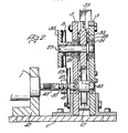
- FIGURE 1 is a side elevation of one emL ment of pile weatherstrip inserting apparatu.
- FIGURE 2 is a section on the line A-A Figure 1; and
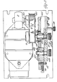
- FIGURE 3 is a sectional plan view of a second, preferred embodiment of apparatus, but showing the apparatus the opposite way round with respect to Figure 2.
- Referring to Figures 1 and 2 of the drawings, the apparatus includes a base 1 and a pair of upstanding support plates 3 and 5. A spindle 7 is mounted for rotation about a fixed axis normal to the plates 3 and 5, there being a drive pulley 9 and a weatherstrip advancing roller 11 keyed to the spindle 7.
- The drive pulley 9 is driven from a
drive shaft 13 by means of a twisted drive belt (not shown) engaging in a groove 15 in thedrive shaft 13. A secondweatherstrip advancing roller 17 is rotatably mounted between the plates 3 and 5 on a spindle 19, the spindle 19 being supported in suitable journals (not shown) mounted inslides 20 supported in a slideway 21 formed in each of the plates 3 and 5 so that the spindle 19 can be moved towards and away from the spindle 7 to accommodate different thicknesses of weatherstrip passing through the nip between therollers 11 and 17. The spindle 19 is rotated by means of a drive belt (not shown) passing round adrive pulley 23 which is keyed to the spindle 19 and engaging with agroove 25 in thedrive shaft 13. - A
further spindle 27 is adjustably supported between the plates 3 and 5 inslides 29 slidably supported inslideways 31 formed in the plates 3 and 5 so that thespindle 27 can be moved towards and away from the spindle 7, the arrangement being such that the direction of movement of thespindle 27 is along a line extending at substantially right angles to the direction of movement of the spindle 19. - A
roller 33 is keyed to thespindle 27 which is driven by means of a twisted endless belt (not shown) engaging around adrive pulley 35 keyed to thespindle 27 and agroove 37 formed in thedrive shaft 13. - As can be seen from Figure 1, each of the
rollers spindles 7, 19 and 27 are so located that a first nip is provided between therollers 11 and 17 and a further nip is provided between therollers 11 and 33 through which nips weatherstrip to be inserted into a groove in an elongated member is entrained. The weatherstrip is fed first into the further nip via aninlet guide 39 and after passing out of the further nip it is guided around the surface of the roller 11 by a guide 41 and thence into the first nip and as it emerges from this first nip it passes into anoutlet guide 43. Means may be provided on theoutlet guide 43 to locate the elongated member having a groove into which the weatherstrip is to be inserted, the arrangement being such that the groove is aligned with the weatherstrip as it emerges from the downstream end of theguide 43. It will be appreciated that because the drive belts for therollers drive shaft 13 rotates clockwise, whereas the roller 11 will rotate in a clockwise direction. We have found that high driving forces can be imparted to the weatherstrip if theroller 33 is provided with a rubber tyre on its surface and the roller 11 is provided with a tyre made of brush-like material, e.g. material known as VELCROSE, the fibres of which mesh with the material of the weatherstrip. Theroller 17, however, which must provide a datum surface for the emerging weatherstrip, must have a hard non-compressible tyre on its surface, for example a coarse emery cloth strip. - The
drive shaft 13 can be driven in any known manner but is particularly designed to be driven by an electric motor. Alternatively, it may be driven by any commercially available electric hand drill from which the chuck is removed and replaced by adrive peg 45. The drill can be supported in asuitable stand 47 mounted on the base 1 of the apparatus.. - By adjusting the position of the
spindles 19 and 27, the required compression and hence grip on the weatherstrip can be achieved and different thicknesses of pile weatherstrip can be accommodated. Likewise, the threeguides - Although the above-described apparatus is only designed to feed one length of weatherstrip at a time into a groove of the elongated member, and hence the
rollers - Normally, for safety reasons, the whole apparatus would be housed within an overall casing and it is envisaged that an automatic cutting head could be mounted on the apparatus to cut the weatherstrip after it has been inserted into its groove. Furthermore, it is envisaged that a microswitch cut-out could be provided which would operate when the weatherstrip reaches the end of its groove.
- The above-described apparatus is small and mobile and because it can be driven by an electric drill it can be set up wherever there is an electrical supply. Furthermore, it can feed weatherstrip into grooves in the elongated members regardless of the location of the groove and of course it can be used by unskilled operators.
- Referring now to Figure 3, parts shown therein which are similar to the parts shown in the embodiment of Figures 1 and 2 have reference numerals 100 higher than those of Figures 1 and 2.
- In Figure 3, an electric motor 2 is provided to advance weatherstrip through the apparatus. The motor 2 has an output shaft 113 which drives a
speed reducer 4 which has anoutput pulley 115. Entrained around theoutput pulley 115 and engaging teeth thereon is a toothed drive belt 106 which is also entrained around a drive pulley 8 on theinput spindle 107 of the weatherstrip advancing roller 111. The roller 111 is keyed to thespindle 107 but can easily be removed and replaced by a different roller by removal of a knurledthumb nut 10 screw- threadedly engaged on a free end of thespindle 107. The roller 111 has a knurled periphery and is cut away at its centre to provide an annular groove 12. The dimensions of this groove are sufficient to receive the weatherstrip, e.g. pile and any barrier film of a length of pile weatherstrip passing through the machine. - The
rollers 133 and 117 (not visible in Figure 3) can be moved towards and away from the roller 111 as in the construction shown particularly in Figure 1 and each of these rollers also has a knurled periphery. Thus, side edge portions of the backing strip of the weatherstrip can be sandwiched between the periphery of two adjacent rollers and tightly held in the nip by suitable adjustment of the tworollers rollers toothed drive belt 6 to the roller 111 is required than occurs in the Figure 1, 2 embodiment. - To adjust the
roller 133 relative to the roller 111, a locking nut 14 is first loosened, whereupon an adjustment stud 16 is rotated to cause theslide 129 to be moved towards or away from thespindle 107. When the correct spacing has been achieved, then the locking nut 14 is tightened so as firmly to fix theslide 129 relative to thesupport plate 105 and hence fix the position of theroller 133 and itsspindle 127 relative to thespindle 107. - It is important that weatherstrip fed into the apparatus is guided firstly into the nip between the
rollers 111 and 133 by a guide-in channel and immediately it passes from this nip it is guided around the surface of the roller 111 into the nip between the roller 111 and theroller 117. Immediately on emerging from this nip the weatherstrip will pass into a groove in a guide- out channel which itself may have a transverse slot therein for cutting off lengths of weatherstrip. - It is preferred that a guard be provided for the mechanism and this may be in the form of a dome which overlies the mechanism and is secured to the plate 5 by one or
more thumb screws 18. - . If desired, the apparatus, instead of being driven by an electric motor through a reduction gear or by means of an electric drill, may be driven by hand by means of a handle and a suitable drive train.
- Although the invention has been particularly designed for inserting flexible prie weatherstrip into a rigid grooved elongate IT -her, it will be appreciated that the invention ald be used to insert any flexible elongate member into any grooved member.
Claims (13)
Applications Claiming Priority (2)
| Application Number | Priority Date | Filing Date | Title |
|---|---|---|---|
| GB4040678 | 1978-10-13 | ||
| GB7840406 | 1978-10-13 |
Publications (2)
| Publication Number | Publication Date |
|---|---|
| EP0010400A1 EP0010400A1 (en) | 1980-04-30 |
| EP0010400B1 true EP0010400B1 (en) | 1982-04-21 |
Family
ID=10500303
Family Applications (1)
| Application Number | Title | Priority Date | Filing Date |
|---|---|---|---|
| EP79302166A Expired EP0010400B1 (en) | 1978-10-13 | 1979-10-10 | Method and apparatus for inserting weatherstrip or the like in a groove |
Country Status (8)
| Country | Link |
|---|---|
| US (1) | US4308653A (en) |
| EP (1) | EP0010400B1 (en) |
| JP (1) | JPS5595795A (en) |
| AU (1) | AU5147579A (en) |
| DE (2) | DE2962579D1 (en) |
| ES (1) | ES484953A1 (en) |
| GR (1) | GR72393B (en) |
| IE (1) | IE48952B1 (en) |
Families Citing this family (13)
| Publication number | Priority date | Publication date | Assignee | Title |
|---|---|---|---|---|
| DE3021031C2 (en) * | 1980-06-03 | 1983-03-31 | Anton Huber GmbH & Co, 8228 Freilassing | Method for attaching at least one trim strip to the surfaces of components, in particular bumpers, bumper cladding, covers, decorative parts or the like. and apparatus for carrying out the method |
| US4377893A (en) * | 1980-12-29 | 1983-03-29 | Schlegel Corporation | Apparatus and method for aligning a weatherstrip guideway with a receiving slot |
| DE3320946C2 (en) * | 1983-06-09 | 1994-09-22 | Schuermann & Co Heinz | Device with a drive device for inserting at least one insulating rod into the receiving grooves of metal profiles |
| US5155890A (en) * | 1988-12-20 | 1992-10-20 | Draftex Industries Limited | Apparatus and method for fitting a flexible strip |
| CA2004418C (en) * | 1988-12-20 | 2000-10-10 | Dieter Goedderz | Apparatus and method for fitting a flexible strip |
| US5031293A (en) * | 1989-09-06 | 1991-07-16 | Draftex Industries Limited | Apparatus for fitting a flexible strip |
| US5179774A (en) * | 1990-05-24 | 1993-01-19 | Ford Motor Company | Apparatus and method for mechanically applying a sealing strip |
| GB2244302B (en) * | 1990-05-24 | 1994-01-19 | Ford Motor Co | Applying weather strips |
| US5758400A (en) * | 1996-06-21 | 1998-06-02 | Donald G. Miller | Weatherstripping insertion machine and method |
| EP1508401A1 (en) * | 2002-05-27 | 2005-02-23 | Vicente Vila, S.L. | Method of inserting a joint into metal, pvc or similar joinery sections |
| US8322005B2 (en) * | 2008-10-23 | 2012-12-04 | Pow Specialty Equipment Inc. | Weather strip installation device |
| US8307524B2 (en) * | 2009-07-08 | 2012-11-13 | Ultrafab, Inc. | Weatherstrip insertion apparatus and method |
| US9120369B2 (en) * | 2011-12-19 | 2015-09-01 | Fca Us Llc | Glass run installation tool |
Family Cites Families (13)
| Publication number | Priority date | Publication date | Assignee | Title |
|---|---|---|---|---|
| US2924007A (en) * | 1960-02-09 | Method for securing rubber-like weather stripping | ||
| US1556234A (en) * | 1923-10-08 | 1925-10-06 | Briggs Mfg Co | Weather-strip-assembling machine |
| US1839429A (en) * | 1929-09-20 | 1932-01-05 | Manning & Co | Tread strip forming machine |
| US2311326A (en) * | 1940-11-25 | 1943-02-16 | Birkin Dimitri | Fastening means |
| US2550898A (en) * | 1947-05-15 | 1951-05-01 | Sterling Molders Inc | Machine for use in making fabrics |
| US2638131A (en) * | 1949-01-14 | 1953-05-12 | Chicopee Mfg Corp | Framing device |
| US2761199A (en) * | 1953-11-27 | 1956-09-04 | Francis E Allen | Caulking tool |
| US3027629A (en) * | 1955-03-21 | 1962-04-03 | Curtis Companies Inc | Apparatus for securing rubber-like weather stripping |
| US3335487A (en) * | 1965-06-25 | 1967-08-15 | Storm Weather Products Co Inc | Machine for inserting pile weather stripping into grooves of storm window extrusions |
| GB1255021A (en) * | 1968-07-26 | 1971-11-24 | Mastabar Beltfasteners Ltd | Guide means for use in joining belt ends together by means of belt fasteners |
| US3608445A (en) * | 1969-06-09 | 1971-09-28 | Acme Highway Prod | Apparatus for inserting seals in pavement grooves |
| US3667105A (en) * | 1970-05-26 | 1972-06-06 | Acme Highway Prod | Strip inserting apparatus |
| US3777353A (en) * | 1970-05-26 | 1973-12-11 | Acme Highway Prod | Strip inserting apparatus |
-
1979
- 1979-10-02 IE IE1872/79A patent/IE48952B1/en unknown
- 1979-10-04 GR GR60183A patent/GR72393B/el unknown
- 1979-10-04 AU AU51475/79A patent/AU5147579A/en not_active Abandoned
- 1979-10-09 US US06/082,920 patent/US4308653A/en not_active Expired - Lifetime
- 1979-10-10 DE DE7979302166T patent/DE2962579D1/en not_active Expired
- 1979-10-10 EP EP79302166A patent/EP0010400B1/en not_active Expired
- 1979-10-11 ES ES484953A patent/ES484953A1/en not_active Expired
- 1979-10-12 JP JP13097179A patent/JPS5595795A/en active Pending
- 1979-10-15 DE DE19797929183U patent/DE7929183U1/en not_active Expired
Also Published As
| Publication number | Publication date |
|---|---|
| AU5147579A (en) | 1980-04-17 |
| GR72393B (en) | 1983-11-01 |
| IE48952B1 (en) | 1985-06-26 |
| EP0010400A1 (en) | 1980-04-30 |
| US4308653A (en) | 1982-01-05 |
| DE2962579D1 (en) | 1982-06-03 |
| IE791872L (en) | 1980-04-13 |
| DE7929183U1 (en) | 1980-04-24 |
| ES484953A1 (en) | 1980-04-16 |
| JPS5595795A (en) | 1980-07-21 |
Similar Documents
| Publication | Publication Date | Title |
|---|---|---|
| EP0010400B1 (en) | Method and apparatus for inserting weatherstrip or the like in a groove | |
| US5368212A (en) | Apparatus for infeeding a cable to an automatic cable processing machine | |
| US4650536A (en) | Machine for applying a portion of photosensitive film to at least one face of a flat plate having a surface area greater than said portion | |
| JPH03245995A (en) | Automatic switching device for blade width of cutting machine | |
| EP0779852B1 (en) | Method and apparatus for skiving belt ends | |
| CA1143546A (en) | Method and apparatus for inserting weatherstrip in a groove | |
| CN210161252U (en) | Printing paper segmentation cutting equipment | |
| JPH0428653A (en) | Cloth supply mechanism for automatic cutting device | |
| FI76272B (en) | FOERFARANDE OCH ANORDNING FOER SLIPNING AEVEN AV SMAO ARBETSSTYCKEN. | |
| EP1355033B1 (en) | Apparatus and method for the production of roller blinds | |
| US6012365A (en) | Reduced maintenance cutting machine | |
| US4601187A (en) | Twisting apparatus and method | |
| KR100605513B1 (en) | Cord paper cutting device for tire cutting process | |
| EP0828041A1 (en) | Applicator device for self-adhesive material strip | |
| SU937187A1 (en) | Machine tool for cutting coiled film | |
| CN217732202U (en) | Automatic cutting device for waste glue | |
| CN211812639U (en) | Cutting machine for release paper | |
| CN215047455U (en) | Virtual cutting device | |
| JPH07290320A (en) | Wire cut electric discharge machine | |
| JP4861576B2 (en) | Endless toothed belt width cutting device and width cutting method thereof | |
| JP2782297B2 (en) | Device for inserting sheet-like material between sliced materials | |
| JPH03170292A (en) | Soft material cutting equipment | |
| CA1237978A (en) | Cutting method and apparatus | |
| KR890007427Y1 (en) | Composite working machine for metal strip | |
| SU1442176A1 (en) | Machine for continuous cutting-out of flat materials |
Legal Events
| Date | Code | Title | Description |
|---|---|---|---|
| PUAI | Public reference made under article 153(3) epc to a published international application that has entered the european phase |
Free format text: ORIGINAL CODE: 0009012 |
|
| AK | Designated contracting states |
Designated state(s): BE DE FR GB IT NL |
|
| 17P | Request for examination filed |
Effective date: 19801015 |
|
| ITF | It: translation for a ep patent filed | ||
| GRAA | (expected) grant |
Free format text: ORIGINAL CODE: 0009210 |
|
| AK | Designated contracting states |
Designated state(s): BE DE FR GB IT NL |
|
| REF | Corresponds to: |
Ref document number: 2962579 Country of ref document: DE Date of ref document: 19820603 |
|
| ITPR | It: changes in ownership of a european patent |
Owner name: CAMBIO RAGIONE SOCIALE;SCHLEGEL ( UK ) HOLDINGS LI |
|
| REG | Reference to a national code |
Ref country code: FR Ref legal event code: CD |
|
| PGFP | Annual fee paid to national office [announced via postgrant information from national office to epo] |
Ref country code: FR Payment date: 19841009 Year of fee payment: 6 |
|
| PGFP | Annual fee paid to national office [announced via postgrant information from national office to epo] |
Ref country code: DE Payment date: 19841106 Year of fee payment: 6 |
|
| PGFP | Annual fee paid to national office [announced via postgrant information from national office to epo] |
Ref country code: BE Payment date: 19841231 Year of fee payment: 6 |
|
| PGFP | Annual fee paid to national office [announced via postgrant information from national office to epo] |
Ref country code: NL Payment date: 19851031 Year of fee payment: 7 |
|
| PG25 | Lapsed in a contracting state [announced via postgrant information from national office to epo] |
Ref country code: BE Effective date: 19861031 |
|
| BERE | Be: lapsed |
Owner name: SCHLEGEL (UK) HOLDINGS LTD Effective date: 19861031 |
|
| PG25 | Lapsed in a contracting state [announced via postgrant information from national office to epo] |
Ref country code: NL Effective date: 19870501 |
|
| NLV4 | Nl: lapsed or anulled due to non-payment of the annual fee | ||
| PG25 | Lapsed in a contracting state [announced via postgrant information from national office to epo] |
Ref country code: FR Free format text: LAPSE BECAUSE OF NON-PAYMENT OF DUE FEES Effective date: 19870630 |
|
| GBPC | Gb: european patent ceased through non-payment of renewal fee | ||
| PG25 | Lapsed in a contracting state [announced via postgrant information from national office to epo] |
Ref country code: DE Effective date: 19870701 |
|
| REG | Reference to a national code |
Ref country code: FR Ref legal event code: ST |
|
| PG25 | Lapsed in a contracting state [announced via postgrant information from national office to epo] |
Ref country code: GB Effective date: 19881118 |
|
| PLBE | No opposition filed within time limit |
Free format text: ORIGINAL CODE: 0009261 |
|
| STAA | Information on the status of an ep patent application or granted ep patent |
Free format text: STATUS: NO OPPOSITION FILED WITHIN TIME LIMIT |