EP0010290B1 - A press for forming particulate tungsten carbide into a blank for cutting tool bit insert and a sinter fixture for compensating shrinkage distortion during sintering - Google Patents
A press for forming particulate tungsten carbide into a blank for cutting tool bit insert and a sinter fixture for compensating shrinkage distortion during sintering Download PDFInfo
- Publication number
- EP0010290B1 EP0010290B1 EP79103989A EP79103989A EP0010290B1 EP 0010290 B1 EP0010290 B1 EP 0010290B1 EP 79103989 A EP79103989 A EP 79103989A EP 79103989 A EP79103989 A EP 79103989A EP 0010290 B1 EP0010290 B1 EP 0010290B1
- Authority
- EP
- European Patent Office
- Prior art keywords
- blank
- centre pin
- sinter
- press
- forming
- Prior art date
- Legal status (The legal status is an assumption and is not a legal conclusion. Google has not performed a legal analysis and makes no representation as to the accuracy of the status listed.)
- Expired
Links
Images

Classifications
-
- B—PERFORMING OPERATIONS; TRANSPORTING
- B23—MACHINE TOOLS; METAL-WORKING NOT OTHERWISE PROVIDED FOR
- B23P—METAL-WORKING NOT OTHERWISE PROVIDED FOR; COMBINED OPERATIONS; UNIVERSAL MACHINE TOOLS
- B23P15/00—Making specific metal objects by operations not covered by a single other subclass or a group in this subclass
- B23P15/28—Making specific metal objects by operations not covered by a single other subclass or a group in this subclass cutting tools
- B23P15/32—Making specific metal objects by operations not covered by a single other subclass or a group in this subclass cutting tools twist-drills
-
- B—PERFORMING OPERATIONS; TRANSPORTING
- B22—CASTING; POWDER METALLURGY
- B22F—WORKING METALLIC POWDER; MANUFACTURE OF ARTICLES FROM METALLIC POWDER; MAKING METALLIC POWDER; APPARATUS OR DEVICES SPECIALLY ADAPTED FOR METALLIC POWDER
- B22F3/00—Manufacture of workpieces or articles from metallic powder characterised by the manner of compacting or sintering; Apparatus specially adapted therefor ; Presses and furnaces
- B22F3/02—Compacting only
- B22F3/03—Press-moulding apparatus therefor
-
- B—PERFORMING OPERATIONS; TRANSPORTING
- B22—CASTING; POWDER METALLURGY
- B22F—WORKING METALLIC POWDER; MANUFACTURE OF ARTICLES FROM METALLIC POWDER; MAKING METALLIC POWDER; APPARATUS OR DEVICES SPECIALLY ADAPTED FOR METALLIC POWDER
- B22F3/00—Manufacture of workpieces or articles from metallic powder characterised by the manner of compacting or sintering; Apparatus specially adapted therefor ; Presses and furnaces
- B22F3/12—Both compacting and sintering
- B22F3/14—Both compacting and sintering simultaneously
-
- B—PERFORMING OPERATIONS; TRANSPORTING
- B22—CASTING; POWDER METALLURGY
- B22F—WORKING METALLIC POWDER; MANUFACTURE OF ARTICLES FROM METALLIC POWDER; MAKING METALLIC POWDER; APPARATUS OR DEVICES SPECIALLY ADAPTED FOR METALLIC POWDER
- B22F5/00—Manufacture of workpieces or articles from metallic powder characterised by the special shape of the product
Description
- The invention relates to a press with contra- rotating jaws and forming cavity closure members for cold pressure-forming of particulate, tungsten carbine into helically-shaped blanks for fitting to a cutting tool bit as inserts; a separate sinter piece has components of similar configuration and function to those of the press and has means built in for continually maintaining correct angular and radial dimensions of the pressed insert blank to compensate for shrinkage and prevent distortion during sintering.
- Sintered tungsten carbide cutting tool bit insert blanks used as cutting edges fixed to high-speed cutting tools such as augers with helical cutting edges are made by pressing tungsten carbide, sometimes mixed with cobalt, under pressure into slabs or ingots from which special shapes are then cut or pressed directly into blanks of desired shape or size. Blanks are then semi-sintered in a non-oxidizing atmosphere at temperatures below 800°C (1472°F) and further formed by machining. Final sintering is then carried out but the sintered carbide so obtained is so hard that the sintered shape can only be corrected by diamond cutter grinding. Uncontrolled shrinkage of the carbide blanks occurs with distortion of shape in existing methods in which carbide powder is brushed onto a spiral or helical cutting tool edge and the carbide is partially sintered on the tool. This requires reheating and bending the tool. Again a strip of pre-sintered or partially sintered carbide is placed along or beside the spiral cutting contour of the cutting tool and fused onto the tool by sintering at a higher temperature than the first-stage temperature. Uncontrolled shrinkage and distortion of the pressed blank occurs during existing sintering processes.
- This causes irregularities in the sintered insert and loss of edge and shoulder sharpness or definition.
- The invention as claimed is intended to remedy the above problem of shrinkage distortion of a sintered blank by controlling or confining those surfaces and edges which are critically affected during shrinkage caused by sintering and namely the whole diameter or radial height and the angular thickness or the thickness of the insert blank in the pitch circle direction of the insert when it is in mounted position on a spiral cutting bit. The whole diameter of the insert is that distance between the root diameter or base of the insert on the cutter bit face and the radial distance from the base to the top of the insert or the outer diameter of the cutter.
- The advantages of the invention are mainly that the correct configuration of a spiral insert blank is obtained by press forming and then maintained during sintering and shrinking of the blank by a sinter piece having distortion-correcting design features built in which continually correct or maintain correct configuration of an insert blank of tungsten carbide during sintering.
- One way of carrying out the invention is described in detail below with reference to drawings which illustrate several specific embodiments, in which:-
- Figure 1 is a perspective view of a forming press in accordance with the invention with a top pressure member removed, and side cavity sealing plate loosened.
- Figure 2 is a plan view of the press with side cavity-sealing plate closed up.
- Figure 3 is a vertical section taken along line A-A of figure 2.
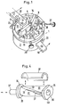
- Figure 4 is a partially exploded view of the shrinkage-compensating, sintering fixture for pressed and formed cutter bit insert blanks for cutting tools.
- The figures 1 to 3 show a cold-forming press for making pre-sinter blanks of tungsten carbide for tool cutter bit inserts or tips for milling machine cutters, augers and other such devices and which comprises a bowl shaped body 1 with a
recessed base 2, aside wall 3 and a central column 4 supporting acentre forming pin 5. The column 4 is bolted to the base of the body by a socket screw 6 the head of which clamps asecuring collar 7 into therecess 8 under the body. There is mounted around the centre pin 5 a compression jaw 9 the base of which is fixed on acompression plate 10 bysocket screws 11. Anejection jaw 12 is similarly fixed to anejection plate 13 beneath the compression plate, bothplates centre pin 5. Theplates collar 14. Thejaws 9, 12 are formed as two matching split segments of a cylindrically curved sleeve split into two segments along blank-shaped cuts which are matching helical or spiral separation cut or cuts forming a helical or spiral forming cavity on one side of thecentre pin 5 and an identical jaw-separation slot on the diametrically opposite side of thepin 5. By an angular movement of the compression jaw 9 or of theejection jaw 12 the complementary, helically-shaped mating surfaces 15 and 16 of the split-shell segments, i.e. the circumferentially facing areas of the forming cavity move towards each other whereas at the same time the two helical surfaces of the jaw-separation slot on the opposite side of thepin 5 move away from each other, and vice versa. To compress a charge by - applying sufficient pressure of the order of 100 pounds, a closing and opening movement of the compression jaw 9 andcompression plate 10 is caused by a reciprocating angular movement of thecompression lever 17 which is powered by suitable means such as apneumatic ram 18. The movement of theejection jaw 12 andejection plate 13 facilitating removal and causing ejection of the compressed blank is effected by theejection lever 19 actuated by a pneumatic ram. The extent of angular travel of thecompression lever 17,plate 10 and jaw 9 is limited by thelimit stop screw 20 mounted on the threadedpost 21 and the screw is adapted to bear against thestop block 22. The extent of the angular travel of theejection lever 19,plate 13 andjaw 12 is limited by the confining edges of theangular slot 23. The forming cavity is sealed against loss of particulate carbide charge material by means of the separate topcavity sealing collar 24 sealed under pressure by vertically reciprocatingmeans 25, the separate cavityside sealing plate 26 clamped in place by upper threadedpress bolt 27 mounted on thepost 28 and the lower threadedpress bolt 29 mounted through the plate-retaining,ring 14. - Referring to figure 4, there is shown a sintering fixture for sintering press-formed, helically-shaped, tungsten carbide cutting tool bit inserts which although is a separate assembly from the press assembly nevertheless has components of the same shape and function and comprises four components of graphite in the form of a spool-shaped body on a centre pin and which is longitudinally split into two sleeve-like segments along
helical separation cuts segments segments circular ends axial bore 36 which is adapted to receive a removable, rod-like pin 37. The round surface of the pin is, when the pin is inserted into the bore, adapted to maintain contact with the bottom surface of a pressed blank and the helical edge walls defining the two sleeve segments are adapted to maintain contact of the sides of a pressed blank. Acover piece 38 of complementary curvature to the spool or sleeve segments is adapted to bear against the top edge of a pressed blank. The flanged ends each have aflattened portion flattened rim portions edge surfaces
Claims (3)
Applications Claiming Priority (3)
| Application Number | Priority Date | Filing Date | Title |
|---|---|---|---|
| AUPD648378 | 1978-10-20 | ||
| AU6483/78 | 1978-10-20 | ||
| AU12336/83A AU1233683A (en) | 1978-10-20 | 1983-03-10 | Sinter fixture for helical or spiral cutting tool tips |
Publications (2)
| Publication Number | Publication Date |
|---|---|
| EP0010290A1 EP0010290A1 (en) | 1980-04-30 |
| EP0010290B1 true EP0010290B1 (en) | 1983-04-27 |
Family
ID=34423622
Family Applications (1)
| Application Number | Title | Priority Date | Filing Date |
|---|---|---|---|
| EP79103989A Expired EP0010290B1 (en) | 1978-10-20 | 1979-10-16 | A press for forming particulate tungsten carbide into a blank for cutting tool bit insert and a sinter fixture for compensating shrinkage distortion during sintering |
Country Status (10)
| Country | Link |
|---|---|
| US (2) | US4303416A (en) |
| EP (1) | EP0010290B1 (en) |
| JP (1) | JPS5597404A (en) |
| AU (2) | AU534619B2 (en) |
| BR (1) | BR7906724A (en) |
| CA (1) | CA1130083A (en) |
| DE (1) | DE2942132C3 (en) |
| DK (1) | DK438679A (en) |
| NO (1) | NO793371L (en) |
| ZA (1) | ZA795575B (en) |
Cited By (1)
| Publication number | Priority date | Publication date | Assignee | Title |
|---|---|---|---|---|
| US11759860B2 (en) | 2020-11-09 | 2023-09-19 | General Electric Company | Systems and methods for compensating a geometry of a green body part based on sintering-induced distortion |
Families Citing this family (8)
| Publication number | Priority date | Publication date | Assignee | Title |
|---|---|---|---|---|
| US5762843A (en) * | 1994-12-23 | 1998-06-09 | Kennametal Inc. | Method of making composite cermet articles |
| AT406240B (en) * | 1996-06-20 | 2000-03-27 | Miba Sintermetall Ag | MOLDING TOOL FOR PRESSING A MOLDED BODY FROM A SINTER POWDER |
| US6908688B1 (en) | 2000-08-04 | 2005-06-21 | Kennametal Inc. | Graded composite hardmetals |
| US8033805B2 (en) | 2007-11-27 | 2011-10-11 | Kennametal Inc. | Method and apparatus for cross-passageway pressing to produce cutting inserts |
| US8079786B2 (en) * | 2009-04-22 | 2011-12-20 | Corbin Manufacturing, Inc. | Tool insert blanks and method of manufacture |
| CN105921959B (en) * | 2016-05-03 | 2018-05-29 | 哈尔滨飞机工业集团有限责任公司 | A kind of rubber pattern circular mold cavity accurate processing method |
| CN115138848B (en) * | 2022-07-13 | 2024-03-12 | 阳江市天骄家庭用品制造有限公司 | Preparation frock of injection integrated into one piece cutter |
| CN115502395B (en) * | 2022-09-17 | 2023-12-01 | 深圳市大族瑞利泰德精密涂层有限公司 | Superfine crystal carbide cutting blade system of processing |
Family Cites Families (10)
| Publication number | Priority date | Publication date | Assignee | Title |
|---|---|---|---|---|
| US1572724A (en) * | 1923-09-08 | 1926-02-09 | Connecticut Telephone & Elec | Power press |
| US1749981A (en) * | 1927-04-11 | 1930-03-11 | Gustavus A Montgomery | Method of making drill stems |
| FR1193090A (en) * | 1958-03-06 | 1959-10-30 | Commissariat Energie Atomique | High load sintering device |
| US3491826A (en) * | 1966-07-15 | 1970-01-27 | Nat Lead Co | Extended opening die casting machine |
| FR1526032A (en) * | 1967-03-13 | 1968-05-24 | Lignes Telegraph Telephon | Process for making small parts by powder molding under pressure |
| US3461506A (en) * | 1967-04-26 | 1969-08-19 | Comstock & Wescott | Die for hot-pressing powdered metal |
| DE2032378B2 (en) * | 1970-06-30 | 1973-06-28 | Marwin Cutting Tools Ltd, Rothley, Leicester (Großbritannien) | METHOD AND DEVICE FOR MANUFACTURING A HELICAL CARBIDE COMPONENT |
| US3960518A (en) * | 1973-07-19 | 1976-06-01 | Hall George H | Method of forming a cutting tool |
| US4203732A (en) * | 1974-03-07 | 1980-05-20 | Cornelius Phaal | Method of making an abrasive product |
| US3932085A (en) * | 1974-07-17 | 1976-01-13 | Stephen Horbach | Mold base |
-
1978
- 1978-10-20 AU AU51531/79A patent/AU534619B2/en not_active Expired - Fee Related
-
1979
- 1979-10-12 US US06/084,296 patent/US4303416A/en not_active Expired - Lifetime
- 1979-10-16 EP EP79103989A patent/EP0010290B1/en not_active Expired
- 1979-10-17 DK DK438679A patent/DK438679A/en unknown
- 1979-10-18 BR BR7906724A patent/BR7906724A/en unknown
- 1979-10-18 DE DE2942132A patent/DE2942132C3/en not_active Expired
- 1979-10-19 NO NO793371A patent/NO793371L/en unknown
- 1979-10-19 CA CA337,977A patent/CA1130083A/en not_active Expired
- 1979-10-19 ZA ZA00795575A patent/ZA795575B/en unknown
- 1979-10-20 JP JP13584179A patent/JPS5597404A/en active Pending
-
1980
- 1980-08-25 US US06/180,942 patent/US4340350A/en not_active Expired - Lifetime
-
1983
- 1983-03-10 AU AU12336/83A patent/AU1233683A/en not_active Abandoned
Cited By (1)
| Publication number | Priority date | Publication date | Assignee | Title |
|---|---|---|---|---|
| US11759860B2 (en) | 2020-11-09 | 2023-09-19 | General Electric Company | Systems and methods for compensating a geometry of a green body part based on sintering-induced distortion |
Also Published As
| Publication number | Publication date |
|---|---|
| BR7906724A (en) | 1980-06-03 |
| JPS5597404A (en) | 1980-07-24 |
| NO793371L (en) | 1980-04-22 |
| EP0010290A1 (en) | 1980-04-30 |
| ZA795575B (en) | 1980-10-29 |
| DE2942132C3 (en) | 1981-10-01 |
| AU534619B2 (en) | 1984-02-09 |
| US4303416A (en) | 1981-12-01 |
| US4340350A (en) | 1982-07-20 |
| AU1233683A (en) | 1983-07-07 |
| AU5153179A (en) | 1980-05-01 |
| DE2942132A1 (en) | 1980-05-22 |
| DE2942132B2 (en) | 1980-11-20 |
| DK438679A (en) | 1980-04-21 |
| CA1130083A (en) | 1982-08-24 |
Similar Documents
| Publication | Publication Date | Title |
|---|---|---|
| EP0638384B1 (en) | A cutting insert | |
| KR101940890B1 (en) | Indexable cutting insert and milling tool | |
| EP0010290B1 (en) | A press for forming particulate tungsten carbide into a blank for cutting tool bit insert and a sinter fixture for compensating shrinkage distortion during sintering | |
| US20170282254A1 (en) | Method and arrangement for manufacturing a cutting insert | |
| US20060024191A1 (en) | Method and apparatus for cross-hole pressing to produce cutting inserts | |
| JP6875515B2 (en) | Cemented Carbide Pressed Product Manufacturing Method and Equipment and Cemented Carbide Pressed Product | |
| US7951455B2 (en) | Methods for manufacturing ultrahard compacts | |
| JP5906355B2 (en) | Method for manufacturing super hard structure | |
| EP0211643B1 (en) | Powder metal consolidation of multiple preforms | |
| CA1126924A (en) | Apparatus and method for compacting prismatic or pyramidal articles from powder material | |
| US11148382B2 (en) | Plane plate of a pressing tool | |
| US11465203B2 (en) | Plane plate of a pressing tool | |
| CN115365497B (en) | Continuous processing and forming process for hard alloy nut | |
| EP3698901B1 (en) | A press tool | |
| CA1156024A (en) | Process and apparatus for the manufacture of sintered tungsten carbide tool tips | |
| CN114310191B (en) | Preparation method of spherical tooth hard alloy die | |
| JPS61257401A (en) | Molding die for piston ring made of sintered alloy | |
| IE84819B1 (en) | Methods for manufacturing ultrahard compacts |
Legal Events
| Date | Code | Title | Description |
|---|---|---|---|
| PUAI | Public reference made under article 153(3) epc to a published international application that has entered the european phase |
Free format text: ORIGINAL CODE: 0009012 |
|
| AK | Designated contracting states |
Designated state(s): CH FR GB IT SE |
|
| 17P | Request for examination filed | ||
| ITF | It: translation for a ep patent filed |
Owner name: STUDIO INGG. FISCHETTI & WEBER |
|
| GRAA | (expected) grant |
Free format text: ORIGINAL CODE: 0009210 |
|
| AK | Designated contracting states |
Designated state(s): CH FR GB IT SE |
|
| ET | Fr: translation filed | ||
| PGFP | Annual fee paid to national office [announced via postgrant information from national office to epo] |
Ref country code: CH Payment date: 19830930 Year of fee payment: 5 |
|
| PGFP | Annual fee paid to national office [announced via postgrant information from national office to epo] |
Ref country code: FR Payment date: 19831010 Year of fee payment: 5 |
|
| PGFP | Annual fee paid to national office [announced via postgrant information from national office to epo] |
Ref country code: SE Payment date: 19840331 Year of fee payment: 6 |
|
| PG25 | Lapsed in a contracting state [announced via postgrant information from national office to epo] |
Ref country code: SE Effective date: 19841017 |
|
| PG25 | Lapsed in a contracting state [announced via postgrant information from national office to epo] |
Ref country code: CH Effective date: 19841031 |
|
| GBPC | Gb: european patent ceased through non-payment of renewal fee | ||
| PG25 | Lapsed in a contracting state [announced via postgrant information from national office to epo] |
Ref country code: FR Free format text: LAPSE BECAUSE OF NON-PAYMENT OF DUE FEES Effective date: 19850628 |
|
| REG | Reference to a national code |
Ref country code: CH Ref legal event code: PL |
|
| REG | Reference to a national code |
Ref country code: FR Ref legal event code: ST |
|
| PG25 | Lapsed in a contracting state [announced via postgrant information from national office to epo] |
Ref country code: GB Effective date: 19881118 |
|
| EUG | Se: european patent has lapsed |
Ref document number: 79103989.4 Effective date: 19851007 |
|
| PLBE | No opposition filed within time limit |
Free format text: ORIGINAL CODE: 0009261 |
|
| STAA | Information on the status of an ep patent application or granted ep patent |
Free format text: STATUS: NO OPPOSITION FILED WITHIN TIME LIMIT |