EP0010290A1 - Presse zum Überführen pulverförmigen Wolframkarbids in ein Bestückungsteil für ein Schneidewerkzeug und Halter, um der während des Sinterns auftretenden Schwindungsverformung entgegen zu wirken - Google Patents
Presse zum Überführen pulverförmigen Wolframkarbids in ein Bestückungsteil für ein Schneidewerkzeug und Halter, um der während des Sinterns auftretenden Schwindungsverformung entgegen zu wirken Download PDFInfo
- Publication number
- EP0010290A1 EP0010290A1 EP79103989A EP79103989A EP0010290A1 EP 0010290 A1 EP0010290 A1 EP 0010290A1 EP 79103989 A EP79103989 A EP 79103989A EP 79103989 A EP79103989 A EP 79103989A EP 0010290 A1 EP0010290 A1 EP 0010290A1
- Authority
- EP
- European Patent Office
- Prior art keywords
- blank
- press
- pin
- sintering
- tool bit
- Prior art date
- Legal status (The legal status is an assumption and is not a legal conclusion. Google has not performed a legal analysis and makes no representation as to the accuracy of the status listed.)
- Granted
Links
- 238000005245 sintering Methods 0.000 title claims abstract description 21
- UONOETXJSWQNOL-UHFFFAOYSA-N tungsten carbide Chemical compound [W+]#[C-] UONOETXJSWQNOL-UHFFFAOYSA-N 0.000 title claims abstract description 11
- 230000006835 compression Effects 0.000 claims abstract description 12
- 238000007906 compression Methods 0.000 claims abstract description 12
- 238000000926 separation method Methods 0.000 claims abstract description 10
- 238000007789 sealing Methods 0.000 claims abstract description 9
- OKTJSMMVPCPJKN-UHFFFAOYSA-N Carbon Chemical compound [C] OKTJSMMVPCPJKN-UHFFFAOYSA-N 0.000 claims abstract description 3
- 229910002804 graphite Inorganic materials 0.000 claims abstract description 3
- 239000010439 graphite Substances 0.000 claims abstract description 3
- 230000005484 gravity Effects 0.000 claims abstract 2
- 230000013011 mating Effects 0.000 claims description 3
- 238000007493 shaping process Methods 0.000 claims 1
- 230000000295 complement effect Effects 0.000 description 2
- 238000000034 method Methods 0.000 description 2
- 239000000203 mixture Substances 0.000 description 2
- 238000005452 bending Methods 0.000 description 1
- 239000010941 cobalt Substances 0.000 description 1
- 229910017052 cobalt Inorganic materials 0.000 description 1
- GUTLYIVDDKVIGB-UHFFFAOYSA-N cobalt atom Chemical compound [Co] GUTLYIVDDKVIGB-UHFFFAOYSA-N 0.000 description 1
- 229910003460 diamond Inorganic materials 0.000 description 1
- 239000010432 diamond Substances 0.000 description 1
- 238000000227 grinding Methods 0.000 description 1
- 238000003754 machining Methods 0.000 description 1
- 239000000463 material Substances 0.000 description 1
- 238000003801 milling Methods 0.000 description 1
- 230000001590 oxidative effect Effects 0.000 description 1
- 239000000843 powder Substances 0.000 description 1
- 238000003825 pressing Methods 0.000 description 1
- 238000003303 reheating Methods 0.000 description 1
- 230000000717 retained effect Effects 0.000 description 1
Images

Classifications
-
- B—PERFORMING OPERATIONS; TRANSPORTING
- B23—MACHINE TOOLS; METAL-WORKING NOT OTHERWISE PROVIDED FOR
- B23P—METAL-WORKING NOT OTHERWISE PROVIDED FOR; COMBINED OPERATIONS; UNIVERSAL MACHINE TOOLS
- B23P15/00—Making specific metal objects by operations not covered by a single other subclass or a group in this subclass
- B23P15/28—Making specific metal objects by operations not covered by a single other subclass or a group in this subclass cutting tools
- B23P15/32—Making specific metal objects by operations not covered by a single other subclass or a group in this subclass cutting tools twist-drills
-
- B—PERFORMING OPERATIONS; TRANSPORTING
- B22—CASTING; POWDER METALLURGY
- B22F—WORKING METALLIC POWDER; MANUFACTURE OF ARTICLES FROM METALLIC POWDER; MAKING METALLIC POWDER; APPARATUS OR DEVICES SPECIALLY ADAPTED FOR METALLIC POWDER
- B22F3/00—Manufacture of workpieces or articles from metallic powder characterised by the manner of compacting or sintering; Apparatus specially adapted therefor ; Presses and furnaces
- B22F3/02—Compacting only
- B22F3/03—Press-moulding apparatus therefor
-
- B—PERFORMING OPERATIONS; TRANSPORTING
- B22—CASTING; POWDER METALLURGY
- B22F—WORKING METALLIC POWDER; MANUFACTURE OF ARTICLES FROM METALLIC POWDER; MAKING METALLIC POWDER; APPARATUS OR DEVICES SPECIALLY ADAPTED FOR METALLIC POWDER
- B22F3/00—Manufacture of workpieces or articles from metallic powder characterised by the manner of compacting or sintering; Apparatus specially adapted therefor ; Presses and furnaces
- B22F3/12—Both compacting and sintering
- B22F3/14—Both compacting and sintering simultaneously
-
- B—PERFORMING OPERATIONS; TRANSPORTING
- B22—CASTING; POWDER METALLURGY
- B22F—WORKING METALLIC POWDER; MANUFACTURE OF ARTICLES FROM METALLIC POWDER; MAKING METALLIC POWDER; APPARATUS OR DEVICES SPECIALLY ADAPTED FOR METALLIC POWDER
- B22F5/00—Manufacture of workpieces or articles from metallic powder characterised by the special shape of the product
Definitions
- the invention relates to a press with contra-rotating jaws and forming cavity closure members for cold pressure-forming of particulate, tungsten carbide into helically-shaped blanks for fitting to a cutting tool bit as inserts; a separate sinter piece has components of similar configuration and function to those of the press and has means built in for continually maintaining correct angular and radial dimensions of the pressed insert blank to compensate for shrinkage and prevent distortion during sintering.
- Sintered tungsten carbide cutting tool bit insert blanks used as cutting edges fixed to high-speed cutting tools such as augers with helical cutting edges are made by pressing tungsten carbide, sometimes mixed with cobalt, under pressure into slabs or ingots from which special shapes are then cut or pressed directly into blanks of desired shape or size. Blanks are then semi-sintered in a non-oxidizing atmosphere at temp-0 eratures below 1472 F and further formed by machining. Final sintering is then carried out but the sintered carbide so obtained is so hard that the sintered shape can only be corrected by diamond cutter grinding.
- Uncontrolled shrinkage of the carbide blanks occurs with distortion of shape in existing methods in which carbide powder is brushed onto a spiral or helical cutting tool edge and the carbide is partially sintered on the tool. This requires reheating and bending the tool. Again a strip of pre-sintered or partially sintered carbide is placed along or beside the spiral cutting contour of the cutting tool and fused onto the tool by sintering at a higher temperature than the first-stage temperature. Uncontrolled shrinkage and distortion of the pressed blank occurs during existing sintering processes.
- the invention as claimed is intended to remedy the above problem of shrinkage distortion of a sintered blank by controlling or confining those surfaces and edges which are critically affected during shrinkage caused by sintering and namely the whole diameter or radial height and the angular thickness or the thickness of the insert blank in the pitch circle direction of the insert when it is in mounted position on a spiral cutting bit.
- the whole diameter of the insert is that distance between the root diameter or base of the insert on the cutter bit face and the radial distance from the base to the top of the insert or the.outer diameter of the cutter.
- the advantages of the invention are mainly that the correct configuration of a spiral insert blank is obtained by press forming and then maintained during sintering and shrinking of the blank by a sinter piece having distortion-correcting design features built in which continually correct or maintain correct configuration of an insert blank of tungsten carbide during sintering.
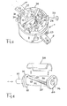
- the figures 1 to 3 show a cold-forming press for making pre- sinter blanks of tungsten carbide for tool cutter bit inserts or tips for milling machine cutters, augers and other such devices and which comprises a bowl shaped body 1 with a recessed base 2, a side wall 3 and a central column 4 supporting a centre forming pin 5.
- the column 4 is bolted to the base of the body by a socket screw 6 the head of which clamps a securing collar 7 into the recess 8 under the body.
- An ejection jaw 12 is similarly fixed to the ejection plate 13 beneath the compression plate, both plates being designed for limited, angular reciprocating movement about the column and centre pin.
- the plates are retained within the body by the plate-retaining collar 14.
- the jaws are formed as matching cylindrically curved sleeves split into two segments along a blank shaped in this example, helical or spiral separation cut or cuts forming a helical or spiral forming cavity on one side of the centre pin and an identical jaw-separation ejection travel slot on the opposite side of the pin.
- the complementary, helically-shaped mating surfaces 15 and 16 of the split-shell segments close towards each other to compress a particulate charge of carbide in an angular movement about the centre pin and move away from the pressed blank and each other when the ejection jaw is actuated.
- the two helical surfaces opposite the pin from the surfaces 15 and 16 close towards each other about the pin when 15 and 16 open up and vice versa.
- the opening and closing movements of the compression jaw 9 and compression plate 10 are actuated by the reciprocating angular movement of the compression lever 17 which is powered by suitable means such as a pneumatic ram 18 to compress a charge by applying sufficient pressure of the order.of 100 pounds.
- the movement of the ejection jaws 12 and ejection plate 13 is effected by the ejection lever 19 actuated by a pneumatic ram.
- the extent of angular travel of the compression lever, plate and jaw is limited by the limit stop screw 20 mounted on the threaded post 21 and the screw is adapted to bear against the stop block 22.
- the extent of the angular travel of the ejection lever, plate and jaw is limited by the confining edges of the angular slot 23.
- the forming cavity is sealed against loss of particulate carbide charge material by,means of the separate top cavity sealing collar 24 sealed under pressure by vertically reciprocating means 25, the separate cavity side sealing plate 26 clamped in place by upper threaded press bolt 27 mounted on the post 28 and the lower threaded press bolt 29 mounted through the plate-retaining ring 14.
- a sintering fixture for sintering press-formed, helically-shaped, tungsten carbide cutting tool bit inserts which although is a separate assembly from the press assembly nevertheless has components of the same shape and function and comprises four components of graphite in the form of a spool-shaped body on a centre pin and which is longitudihally split into two sleeve-like segments along helical separation cuts 15 and 16 in the press or 32 and 33 in the fixture which divide the segments 30 and 31.
- the segments 30 and 31 have flanged partially circular ends 34 and 35 and a longitudinal or axial bore 36 which is adapted to receive a removeable, rod-like pin 37
- the round surface of the pin is, when the pin is inserted into the bore, adapted to maintain contact with the bottom surfaceof a pressed blank and the helical edge walls defining the two sleeve segments are adapted to maintain contact of the sides of a pressed blank.
- a cover piece 38 of complementary curvature to the spool or sleeve segments is adapted to bear against the top edge of a pressed blank and the flanged ends each have a flattened portion 39 and 40, respectively which, when the assembled fixture containing a pressed blank is placed upon the flat surface in a sinter furnace, the flattened rim portions 39 and 40 which are each off-set with respect to each other in an angular direction about the longit- udihal axis of the sintering fixture produce a torque or twisting action of each segment of the shell towards each other so that the edge surfaces 32 and 33 close up or bear against a helical blank to counteract angular shrinkage distortion in the direction of the pitch circle of the sintered blank insert installed on or against the cutting edge profile 0 of a cutting tool bit when the blank is sintered at 1500 to 1600 C, depending on the composition of the sinter mix.
Landscapes
- Engineering & Computer Science (AREA)
- Mechanical Engineering (AREA)
- Manufacturing & Machinery (AREA)
- Powder Metallurgy (AREA)
- Ceramic Products (AREA)
- Carbon And Carbon Compounds (AREA)
Applications Claiming Priority (3)
| Application Number | Priority Date | Filing Date | Title |
|---|---|---|---|
| AU6483/78 | 1978-10-20 | ||
| AUPD648378 | 1978-10-20 | ||
| AU12336/83A AU1233683A (en) | 1978-10-20 | 1983-03-10 | Sinter fixture for helical or spiral cutting tool tips |
Publications (2)
| Publication Number | Publication Date |
|---|---|
| EP0010290A1 true EP0010290A1 (de) | 1980-04-30 |
| EP0010290B1 EP0010290B1 (de) | 1983-04-27 |
Family
ID=34423622
Family Applications (1)
| Application Number | Title | Priority Date | Filing Date |
|---|---|---|---|
| EP79103989A Expired EP0010290B1 (de) | 1978-10-20 | 1979-10-16 | Presse zum Überführen pulverförmigen Wolframkarbids in ein Bestückungsteil für ein Schneidewerkzeug und Halter, um der während des Sinterns auftretenden Schwindungsverformung entgegen zu wirken |
Country Status (10)
| Country | Link |
|---|---|
| US (2) | US4303416A (de) |
| EP (1) | EP0010290B1 (de) |
| JP (1) | JPS5597404A (de) |
| AU (2) | AU534619B2 (de) |
| BR (1) | BR7906724A (de) |
| CA (1) | CA1130083A (de) |
| DE (1) | DE2942132C3 (de) |
| DK (1) | DK438679A (de) |
| NO (1) | NO793371L (de) |
| ZA (1) | ZA795575B (de) |
Cited By (2)
| Publication number | Priority date | Publication date | Assignee | Title |
|---|---|---|---|---|
| AT406240B (de) * | 1996-06-20 | 2000-03-27 | Miba Sintermetall Ag | Formwerkzeug zum pressen eines formkörpers aus einem sinterpulver |
| CN115138848A (zh) * | 2022-07-13 | 2022-10-04 | 阳江市天骄家庭用品制造有限公司 | 一种新型注射一体成型刀具的制备工装 |
Families Citing this family (9)
| Publication number | Priority date | Publication date | Assignee | Title |
|---|---|---|---|---|
| US5762843A (en) * | 1994-12-23 | 1998-06-09 | Kennametal Inc. | Method of making composite cermet articles |
| US6908688B1 (en) | 2000-08-04 | 2005-06-21 | Kennametal Inc. | Graded composite hardmetals |
| US8033805B2 (en) | 2007-11-27 | 2011-10-11 | Kennametal Inc. | Method and apparatus for cross-passageway pressing to produce cutting inserts |
| US8079786B2 (en) * | 2009-04-22 | 2011-12-20 | Corbin Manufacturing, Inc. | Tool insert blanks and method of manufacture |
| CN105921959B (zh) * | 2016-05-03 | 2018-05-29 | 哈尔滨飞机工业集团有限责任公司 | 一种橡胶模圆形型腔精确加工方法 |
| WO2021126324A1 (en) | 2019-12-17 | 2021-06-24 | Kennametal Inc. | Additive manufacturing techniques and applications thereof |
| US11759860B2 (en) | 2020-11-09 | 2023-09-19 | General Electric Company | Systems and methods for compensating a geometry of a green body part based on sintering-induced distortion |
| CN118287675B (zh) * | 2022-04-25 | 2025-10-17 | 泉州众志新材料科技有限公司 | 一种金刚石刀头的制备方法 |
| CN115502395B (zh) * | 2022-09-17 | 2023-12-01 | 深圳市大族瑞利泰德精密涂层有限公司 | 一种超细晶硬质合金切削刀片加工系统 |
Citations (4)
| Publication number | Priority date | Publication date | Assignee | Title |
|---|---|---|---|---|
| US1749981A (en) * | 1927-04-11 | 1930-03-11 | Gustavus A Montgomery | Method of making drill stems |
| FR1193090A (fr) * | 1958-03-06 | 1959-10-30 | Commissariat Energie Atomique | Dispositif de frittage sous charge élevée |
| FR1526032A (fr) * | 1967-03-13 | 1968-05-24 | Lignes Telegraph Telephon | Procédé de réalisation de petites pièces par moulage de poudre sous pression |
| DE2032378A1 (de) * | 1970-06-30 | 1972-06-15 | Marwin Cutting Tools Ltd | Spiralförmiges Werkzeugbestuckungs teil sowie Verfahren und Vorrichtung zu dessen Herstellung |
Family Cites Families (6)
| Publication number | Priority date | Publication date | Assignee | Title |
|---|---|---|---|---|
| US1572724A (en) * | 1923-09-08 | 1926-02-09 | Connecticut Telephone & Elec | Power press |
| US3491826A (en) * | 1966-07-15 | 1970-01-27 | Nat Lead Co | Extended opening die casting machine |
| US3461506A (en) * | 1967-04-26 | 1969-08-19 | Comstock & Wescott | Die for hot-pressing powdered metal |
| US3960518A (en) * | 1973-07-19 | 1976-06-01 | Hall George H | Method of forming a cutting tool |
| US4203732A (en) * | 1974-03-07 | 1980-05-20 | Cornelius Phaal | Method of making an abrasive product |
| US3932085A (en) * | 1974-07-17 | 1976-01-13 | Stephen Horbach | Mold base |
-
1978
- 1978-10-20 AU AU51531/79A patent/AU534619B2/en not_active Expired - Fee Related
-
1979
- 1979-10-12 US US06/084,296 patent/US4303416A/en not_active Expired - Lifetime
- 1979-10-16 EP EP79103989A patent/EP0010290B1/de not_active Expired
- 1979-10-17 DK DK438679A patent/DK438679A/da unknown
- 1979-10-18 DE DE2942132A patent/DE2942132C3/de not_active Expired
- 1979-10-18 BR BR7906724A patent/BR7906724A/pt unknown
- 1979-10-19 CA CA337,977A patent/CA1130083A/en not_active Expired
- 1979-10-19 ZA ZA00795575A patent/ZA795575B/xx unknown
- 1979-10-19 NO NO793371A patent/NO793371L/no unknown
- 1979-10-20 JP JP13584179A patent/JPS5597404A/ja active Pending
-
1980
- 1980-08-25 US US06/180,942 patent/US4340350A/en not_active Expired - Lifetime
-
1983
- 1983-03-10 AU AU12336/83A patent/AU1233683A/en not_active Abandoned
Patent Citations (4)
| Publication number | Priority date | Publication date | Assignee | Title |
|---|---|---|---|---|
| US1749981A (en) * | 1927-04-11 | 1930-03-11 | Gustavus A Montgomery | Method of making drill stems |
| FR1193090A (fr) * | 1958-03-06 | 1959-10-30 | Commissariat Energie Atomique | Dispositif de frittage sous charge élevée |
| FR1526032A (fr) * | 1967-03-13 | 1968-05-24 | Lignes Telegraph Telephon | Procédé de réalisation de petites pièces par moulage de poudre sous pression |
| DE2032378A1 (de) * | 1970-06-30 | 1972-06-15 | Marwin Cutting Tools Ltd | Spiralförmiges Werkzeugbestuckungs teil sowie Verfahren und Vorrichtung zu dessen Herstellung |
Cited By (3)
| Publication number | Priority date | Publication date | Assignee | Title |
|---|---|---|---|---|
| AT406240B (de) * | 1996-06-20 | 2000-03-27 | Miba Sintermetall Ag | Formwerkzeug zum pressen eines formkörpers aus einem sinterpulver |
| CN115138848A (zh) * | 2022-07-13 | 2022-10-04 | 阳江市天骄家庭用品制造有限公司 | 一种新型注射一体成型刀具的制备工装 |
| CN115138848B (zh) * | 2022-07-13 | 2024-03-12 | 阳江市天骄家庭用品制造有限公司 | 一种注射一体成型刀具的制备工装 |
Also Published As
| Publication number | Publication date |
|---|---|
| BR7906724A (pt) | 1980-06-03 |
| AU534619B2 (en) | 1984-02-09 |
| CA1130083A (en) | 1982-08-24 |
| DE2942132B2 (de) | 1980-11-20 |
| US4340350A (en) | 1982-07-20 |
| JPS5597404A (en) | 1980-07-24 |
| US4303416A (en) | 1981-12-01 |
| NO793371L (no) | 1980-04-22 |
| DK438679A (da) | 1980-04-21 |
| DE2942132C3 (de) | 1981-10-01 |
| DE2942132A1 (de) | 1980-05-22 |
| AU5153179A (en) | 1980-05-01 |
| AU1233683A (en) | 1983-07-07 |
| EP0010290B1 (de) | 1983-04-27 |
| ZA795575B (en) | 1980-10-29 |
Similar Documents
| Publication | Publication Date | Title |
|---|---|---|
| EP0638384B1 (de) | Schneideinsatz | |
| US9713845B2 (en) | Method and arrangement for manufacturing a cutting insert | |
| EP0010290A1 (de) | Presse zum Überführen pulverförmigen Wolframkarbids in ein Bestückungsteil für ein Schneidewerkzeug und Halter, um der während des Sinterns auftretenden Schwindungsverformung entgegen zu wirken | |
| US7731488B2 (en) | Method and apparatus for manufacturing a cutting insert | |
| JP6875515B2 (ja) | 超硬合金プレス品の製造方法および製造装置ならびに超硬合金プレス品 | |
| EP1558415B1 (de) | Verfahren und vorrichtung zum pressen von formkörpern mit durchgangslöchern zum herstellen von schneideinsätzen | |
| CA1126924A (en) | Apparatus and method for compacting prismatic or pyramidal articles from powder material | |
| US11148382B2 (en) | Plane plate of a pressing tool | |
| US11465203B2 (en) | Plane plate of a pressing tool | |
| US11479007B2 (en) | Plane plate of a pressing tool | |
| EP3698901B1 (de) | Presswerkzeug | |
| CA1156024A (en) | Process and apparatus for the manufacture of sintered tungsten carbide tool tips | |
| JP6354893B1 (ja) | 切削インサート用圧粉体の粉末成形プレス方法および粉末成形プレス装置 | |
| JPS63183107A (ja) | 焼結ヘリカルギヤの成形装置 | |
| JP2018199152A (ja) | 切削インサート用圧粉体の粉末成形プレス方法および粉末成形プレス装置 | |
| JPS61257401A (ja) | 焼結合金製ピストンリングの成形金型 |
Legal Events
| Date | Code | Title | Description |
|---|---|---|---|
| PUAI | Public reference made under article 153(3) epc to a published international application that has entered the european phase |
Free format text: ORIGINAL CODE: 0009012 |
|
| AK | Designated contracting states |
Designated state(s): CH FR GB IT SE |
|
| 17P | Request for examination filed | ||
| ITF | It: translation for a ep patent filed | ||
| GRAA | (expected) grant |
Free format text: ORIGINAL CODE: 0009210 |
|
| AK | Designated contracting states |
Designated state(s): CH FR GB IT SE |
|
| ET | Fr: translation filed | ||
| PGFP | Annual fee paid to national office [announced via postgrant information from national office to epo] |
Ref country code: CH Payment date: 19830930 Year of fee payment: 5 |
|
| PGFP | Annual fee paid to national office [announced via postgrant information from national office to epo] |
Ref country code: FR Payment date: 19831010 Year of fee payment: 5 |
|
| PGFP | Annual fee paid to national office [announced via postgrant information from national office to epo] |
Ref country code: SE Payment date: 19840331 Year of fee payment: 6 |
|
| PG25 | Lapsed in a contracting state [announced via postgrant information from national office to epo] |
Ref country code: SE Effective date: 19841017 |
|
| PG25 | Lapsed in a contracting state [announced via postgrant information from national office to epo] |
Ref country code: CH Effective date: 19841031 |
|
| GBPC | Gb: european patent ceased through non-payment of renewal fee | ||
| PG25 | Lapsed in a contracting state [announced via postgrant information from national office to epo] |
Ref country code: FR Free format text: LAPSE BECAUSE OF NON-PAYMENT OF DUE FEES Effective date: 19850628 |
|
| REG | Reference to a national code |
Ref country code: CH Ref legal event code: PL |
|
| REG | Reference to a national code |
Ref country code: FR Ref legal event code: ST |
|
| PG25 | Lapsed in a contracting state [announced via postgrant information from national office to epo] |
Ref country code: GB Effective date: 19881118 |
|
| EUG | Se: european patent has lapsed |
Ref document number: 79103989.4 Effective date: 19851007 |
|
| PLBE | No opposition filed within time limit |
Free format text: ORIGINAL CODE: 0009261 |
|
| STAA | Information on the status of an ep patent application or granted ep patent |
Free format text: STATUS: NO OPPOSITION FILED WITHIN TIME LIMIT |