EP0010269A1 - Process and apparatus for splitting a stream of lubricant droplets in a carrying medium into at least two separate outgoing flows - Google Patents
Process and apparatus for splitting a stream of lubricant droplets in a carrying medium into at least two separate outgoing flows Download PDFInfo
- Publication number
- EP0010269A1 EP0010269A1 EP79103935A EP79103935A EP0010269A1 EP 0010269 A1 EP0010269 A1 EP 0010269A1 EP 79103935 A EP79103935 A EP 79103935A EP 79103935 A EP79103935 A EP 79103935A EP 0010269 A1 EP0010269 A1 EP 0010269A1
- Authority
- EP
- European Patent Office
- Prior art keywords
- flows
- channels
- output
- flow
- oil
- Prior art date
- Legal status (The legal status is an assumption and is not a legal conclusion. Google has not performed a legal analysis and makes no representation as to the accuracy of the status listed.)
- Granted
Links
Images
Classifications
-
- F—MECHANICAL ENGINEERING; LIGHTING; HEATING; WEAPONS; BLASTING
- F16—ENGINEERING ELEMENTS AND UNITS; GENERAL MEASURES FOR PRODUCING AND MAINTAINING EFFECTIVE FUNCTIONING OF MACHINES OR INSTALLATIONS; THERMAL INSULATION IN GENERAL
- F16N—LUBRICATING
- F16N7/00—Arrangements for supplying oil or unspecified lubricant from a stationary reservoir or the equivalent in or on the machine or member to be lubricated
- F16N7/30—Arrangements for supplying oil or unspecified lubricant from a stationary reservoir or the equivalent in or on the machine or member to be lubricated the oil being fed or carried along by another fluid
- F16N7/32—Mist lubrication
Definitions
- the invention relates to a method for dividing a droplet-shaped lubricant brought up in a carrier medium into at least two separate output flows, preferably for dividing oil drops brought up in a turbulent air flow, and a device for carrying out this method.
- Oil mist lubrication in which the lubricating oil is atomized in a central oil mist device, is known for the supply of lubricant to friction points.
- the surface tension of the microfine oil particles is greater than the attraction of the oil particles.
- the microfine nebulized oil is in a state that resembles a gaseous state of matter. In this state, the microfine nebulized oil can be fed from the central nebulizer to the individual friction points via distributors.
- the microfine oil is re-compressed in front of the lubrication points in appropriate nozzles, so that teardrop-shaped oil liquid is formed again
- a disadvantage of this oil mist system is that it is not possible to completely bring the oil mist back together in a droplet shape, and that the remaining oil mist can then cause environmental pollution or damage.
- the oil mist can only be transported at low speeds, since it is the only way that the micro-atomized state of the oil can last. ge is maintained when the flow is laminar. When the flow becomes turbulent, the oil particles collide. collect and combine to form such large drops of oil that it is again liquid. In this state, no division is possible and the oil runs back to the tank.
- the required low flow rate which must be lower than the critical flow rate corresponding to the Reynolds number, requires relatively large cross sections for the lines.
- the invention has for its object to provide a method by means of which a droplet-shaped lubricating medium introduced in a carrier medium can be divided into at least two separate output flows, in which the division takes place independently of the position without moving parts, so that the influence of gravity acts on the oil drops no longer play a role in the distribution, and thus the advantages known from the oil mist system are combined with the known advantages of the oil-air system without the respective disadvantages.
- the invention provides d ate the input flow is divided into a plurality of intermediate flows, and in each case one group of intermediate flows merges into one of the output flows, and the intermediate flows at the transitions from the input flow into the intermediate flows have overall spatial preferred directions of equal value in groups.
- the invention is based on the idea of dividing the lubricant between the inlet flow and the outlet flows into a large number of intermediate flows. When dividing an inlet flow into two outlet flows, it can be provided, for example, that the inlet flow is first divided into eight intermediate flows, four of which are combined into one outlet flow.
- the term "equivalent spatial preferred directions" is to be understood in such a way that two intermediate flows each open at the bottom of the input channel, two intermediate flows branch off at the two opposite side walls and two intermediate flows each at the top of the channel.
- the intermediate flows thus branch off in four different positions, namely on the bottom, on the opposite sides and on the top.
- One of the intermediate flows from the bottom, from the opposite side and from the top is then brought together into one exit flow, while the remaining four intermediate flows are brought together into the other exit flow. Since each output flow therefore has four intermediate flows with different spatial preferred directions at the transition from the input flow to the intermediate
- the associated distribution is independent of the position, since the influence of the gravitational force on the oil drops has the same effect on the distribution in every position.
- the method is of course not limited to the exemplary embodiment described above, but of course a division into more than two outlet flows is possible, and a significantly larger number of intermediate flows than mentioned can also be provided.
- the method according to the invention has the advantages that it works unaffected by the installation position of the arrangement, that it can do without moving elements. Another advantage is that the ratio of carrier medium to lubricating medium is maintained according to the pre-metering, so that the distribution process leaves this ratio unaffected.
- the method can be used regardless of the viscosity of the lubricant. It can be used for the entire range from thin to highly viscous lubricants.
- the lubricant for example oil
- the lubricant remains liquid so that the oil can be sprayed at the friction point with the help of the air used for the transport. No oil mist escapes, making the process environmentally friendly.
- the ratio of carrier medium to lubricant at the control center can also vary depending on the application case. Compared to the oil mist system, a higher delivery speed can be used, which leads to small cross sections.
- the method according to the invention works without wear. It is not necessary to heat the oil to reduce the oil viscosity.
- a device for carrying out the method according to the invention with an input channel assigned to the input flow and a plurality of output channels assigned to the output flows is characterized in that the output channels are connected to the input channel via a group of the same number of a plurality of intermediate channels, and the spatial preferred directions of the individual Intermediate channels assigned to groups at the transitions to the input channel are equally divided among the groups.
- the exit channels have passage cross sections of different sizes.
- junctions of the intermediate channels in the input channel are arranged next to one another radially around the imaginary central axis of the input channel, and the intermediate channels with adjoining junctions are assigned to different groups.
- throttle devices are provided in the output channels.
- the distribution ratio can be designed differently by means of these throttle devices. If the throttle devices are designed, for example, in the form of diaphragms, and the diaphragm openings in the output channels are of the same size, then there is a uniform division. If the diaphragm openings are of different sizes, different flow distributions result depending on the cross-sectional differences.
- the input channel having an internal toothing and the intermediate channels are formed in that inserted into the input channel gears having a number of teeth - are inserted that is different from that of the internal teeth.
- the gaps thus created in the toothing and distributed over the circumference form the intermediate channels, which are then connected in groups to the output channels.
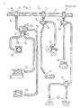
- An oil-air mixture (in which the oil is not contained in a nebulized state but in a drop-shaped state) is introduced in a turbulent air flow in the direction of arrow A in a line 1 from a central device (not shown).
- the line 1 has several distributors 2, 3, 4 ..., to which branch lines 5, 6, 7 connect. Further distributors 8, 16, 9, 10 and 11 are connected to the branch lines. From these distributors, the oil-air mixture, which is denoted by 12, is supplied with friction points or lubrication points, which can be designed as roller bearings, slide bearings, sliding surfaces, gear wheels, chains or the like, and which are shown schematically in FIG. 1 .
- the branch lines leading to the friction points are designated 13 in the distributor 8 and 14 and 15 in the distributor 16.
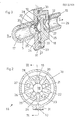
- the distributor 16 is shown schematically on an enlarged scale in FIGS. 2 and 3 and is explained below.
- the line 5 forms in its interior an inlet channel 17 for an inlet flow in the direction of arrow B for the oil drops brought up in a turbulent air flow.
- the input channel 17 has a closed one Front end 18 on.
- a total of ten intermediate channels 19 to 28 are arranged distributed in the radial direction over the inner circumference of the input channel 17.
- the intermediate channels 19, 21, 23, 25 and 27 all lead into an outlet channel 29 through which the oil-air mixture is fed to the friction point in the direction of arrow C.
- the intermediate channels 20, 22, 24, 26 and 28 lying between the just mentioned intermediate channels all open into an annular channel 30, which in turn opens into a channel 31, in which oil-air mixture flows in the direction of arrow D.
- Throttle devices 32 and 33 are provided in the output channels 29 and 31, respectively, by means of which the cross section of the output channels can be designed to be of different sizes. This enables a wide range of variations in the distribution ratios. If, for example, the throttle device has an opening radius of 0.1 mm, then this corresponds to a cross section of 0.0314 mm 2 . In contrast, if the opening of the throttle device in another output channel has a bore with a radius of 0.2 mm, this corresponds to a cross-section of 0.1256 mm 2 , i.e. four times the cross-sectional value of the other output channel (assuming that contrary to the neichnerical Representation the cross sections of the output channels are the same size). If the radius of a hole is 1 mm, the cross-section is already a hundred times the value compared to a hole of 0.1 mm radius.
- the carrier medium prefferably be the working medium at the same time.
Abstract
Description
Die Erfindung betrifft ein Verfahren zum Aufteilen von einem in einem Trägermedium herangeführten tropfenförmigen Schmiermedium in wenigstens zwei voneinander getrennte Ausgangsströmungen, vorzugsweise zum Aufteilen von in einer turbulenten Luftströmung herangeführten Öltropfen, sowie eine Vorrichtung zur Durchführung dieses Verfahrens.The invention relates to a method for dividing a droplet-shaped lubricant brought up in a carrier medium into at least two separate output flows, preferably for dividing oil drops brought up in a turbulent air flow, and a device for carrying out this method.
Für die Zufuhr von Schmiermedium zu Reibstellen ist die Ölnebelschmierung bekannt, bei der in einem zentralen Ölnebelgerät das Schmieröl mikrofein vernebelt wird. Die Oberflächenspannung der mikrofeinen Ölpartikelchen ist größer als die Anziehungskraft der Ölpartikel. Dies hat zur Folge, daß sich das mikrofein vernebelte Öl in einem Zustand befindet, welcher einem gasförmigen Aggregatzustand ähnelt. Das mikrofein vernebelte Öl kann in diesem Zustand von dem zentralen Vernebelungsgerät über Verteiler den einzelnen Reibstellen zugeführt werden. Das mikrofein vermebelte Öl wird vor den Schmierstellen in entsprechenden Düsen rückverdichtet, so daß sich dort wieder tropfenförmige Ölflüssigkeit bildet Ein Nachteil dieses Ölnebelsystems besteht darin, daß es nicht möglich ist, den Ölnebel vollständig wieder in eine Tropfenform zusammenzuführen, und daß dann durch den übrigbleibenden Ölnebel eine Umweltverschmutzung bzw. Umweltschädigung auftreten kann. Weiterhin kann der Ölnebel nur mit geringen Geschwindigkeiten transportiert werden, da er mikrofein vernebelte Aggregatzustand des Öls nur so lan. ge aufrechterhalten bleibt, als die Strömung laminar ist. Wenn die Strömung turbulent wird, prallen die Ölpartikel zu. sammen und vereinigen sich zu so großen Öltropfen, daß es sich wiederum um Flüssigkeit handelt. In diesem Zustand ist keine Aufteilung möglich, und das Öl läuft zum Behälter zurück. Die erforderliche geringe Strömungsgeschwindigkeit, die geringer sein muß als die der Reynolds-Zahl entsprechende kritische Strömungsgeschwindigkeit, bedingt relativ grosse Querschnitte für die Leitungen.Oil mist lubrication, in which the lubricating oil is atomized in a central oil mist device, is known for the supply of lubricant to friction points. The surface tension of the microfine oil particles is greater than the attraction of the oil particles. As a result, the microfine nebulized oil is in a state that resembles a gaseous state of matter. In this state, the microfine nebulized oil can be fed from the central nebulizer to the individual friction points via distributors. The microfine oil is re-compressed in front of the lubrication points in appropriate nozzles, so that teardrop-shaped oil liquid is formed again A disadvantage of this oil mist system is that it is not possible to completely bring the oil mist back together in a droplet shape, and that the remaining oil mist can then cause environmental pollution or damage. Furthermore, the oil mist can only be transported at low speeds, since it is the only way that the micro-atomized state of the oil can last. ge is maintained when the flow is laminar. When the flow becomes turbulent, the oil particles collide. collect and combine to form such large drops of oil that it is again liquid. In this state, no division is possible and the oil runs back to the tank. The required low flow rate, which must be lower than the critical flow rate corresponding to the Reynolds number, requires relatively large cross sections for the lines.
Es ist auch bekannt, einer Schmierstelle Schmiermedium in einer turbulenten Luftströmung zuzuführen. Bei diesem Verfahren treten jedoch Probleme bei der Aufteilung des tropfenförmigen, in der Luftströmung herangeführten Schmiermediums auf die einzelnen Schmierstellen auf. An den Abzweigstellen bewirkt nämlich die Schwerkraft, daß sich jeweils ein größerer Teil der Öltropfen an der jeweils untersten Stelle des Verteilers befindet. Somit ist die Verteilung lageabhängig, was sich beispielsweise bei auf Fahrzeugen angebrachten Schmieranlagen negativ auswirkt. Es sind Versuche unternommen worden, Verteiler mit beweglichen Elementen einzusetzen. Diese Versuche haben jedoch zu keinen praktischen Erfolgen geführt. Weiterhin wurde bereits vorgeschlagen, in den Verteilern gesonderte Luftwirbel (ähnlich einem Zyklon) zu erzeugen. Da jedoch die Viskosität des Schmiermediums in weiten Grenzen schwanken kann, hat sich auch dieser Vorschlag als nicht erfolgreich erwiesen. Im Hinblick darauf, daß die Schmieröle infolge ihrer unterschiedlichen Viskositäten strömungsmäßig nicht berechenbar sind, und da das Verhältnis der Luftmenge zu der Ölmenge je nach Bedarf unterschiedlich ist, so daß die Einbaulage eine entsprechende Rolle spielt, ist es üblich, bei einer Schmierung mit einem Öl-Luftgemisch, welches in einer turbulenten Luftströmung herangeführt wird, dem Luftstrom die Ölmenge für jede Reibstelle gesondert dosiert zuzugeben.It is also known to supply lubricant to a lubrication point in a turbulent air flow. With this method, however, problems arise in the distribution of the drop-shaped lubricant introduced into the air flow among the individual lubrication points. At the branch points, gravity causes a larger part of the oil drops to be at the lowest point of the distributor. The distribution is therefore dependent on the position, which has a negative impact, for example, on lubrication systems installed on vehicles. They are attempts undertaken to use distributors with movable elements. However, these attempts have not led to practical success. Furthermore, it has already been proposed to generate separate air vortices (similar to a cyclone) in the distributors. However, since the viscosity of the lubricant can fluctuate within wide limits, this proposal has also proved unsuccessful. In view of the fact that, due to their different viscosities, the lubricating oils cannot be calculated in terms of flow, and since the ratio of the amount of air to the amount of oil varies as required, so that the installation position plays a corresponding role, it is common for lubrication with an oil -Air mixture, which is introduced in a turbulent air flow, to add the oil quantity to the air flow separately for each friction point.
Der Erfindung liegt die Aufgabe zugrunde, ein Verfahren zu schaffen, mittels dessen eine Aufteilung eines in eimem Trägermedium herangeführten tropfenförmigen Schmiermediums in wenigstens zwei voneinander getrennte Ausgangsströmungen erzielt werden kann, bei dem die Aufteilung lageunabhängig ohne bewegliche Teile erfolgt, so daß der Einfluß der Schwerkraft auf die Öltropfen bei der Verteilung keine Rolle mehr spielt, und daß somit die von dem Öl-Nebelsystem bekannten Vorteile mit den bekannten Vorteilen des Öl-Luftsystems ohne die jeweiligen Nachteile kombiniert werden.The invention has for its object to provide a method by means of which a droplet-shaped lubricating medium introduced in a carrier medium can be divided into at least two separate output flows, in which the division takes place independently of the position without moving parts, so that the influence of gravity acts on the oil drops no longer play a role in the distribution, and thus the advantages known from the oil mist system are combined with the known advantages of the oil-air system without the respective disadvantages.
Zum Lösung dieser Aufgabe ist erfindungsgemäß vorgesehen, daß die Eingangsströmung in eine Mehrzahl von Zwischenströmungen unterteilt wird, und jeweils eine Gruppe von Zwischenströmungen in eine der Ausgangsströmungen mundet, und die Zwischenströmungen an den Übergängen von der Eingangsströmung in die Zwischenströmungen gruppenweise insgesamt gleichwertige räumliche Vorzugsrichtungen aufweisen. Der Erfindung liegt der Gedanke zugrunde, das Schmiermedium zwiscnen der Eingangsströmung und den Ausgangsströmungen in eine Vielzahl von Zwischenströmungen zu unterteilen. Bei der Aufteilung einer Eingangsströmung in zwei Ausgangsströmungen kann beispielsweise vorgesehen sein, daß die Eingangsströmung zunächst in acht Zwischenströmungen unterteilt wird von denen jeweils vier in eine Ausgangsströmung zusammengeführt werden. Der Begriff "gleichwertige räumliche Vorzugsrichtungen" ist dabei so zu verstehen, daß jeweils zwei Zwischenströmungen am Boden des Eingangskanals einmünden, jeweils zwei Zwischenströmungen an den beiden gegenüberliegenden Seitenwänden und jeweils zwei Zwischenströmungen an der Oberseite des Kanals abzweigen. Die Zwischenströmungen zweigen somit in vier unterschiedlichen Lagen ab, und zwar am Boden, an den gegenüberliegenden Seiten und an der Oberseite. Je eine der Zwischenströmungen vom Boden, von den gegenüberliegenden und der Oberseite wird dann in die eine Ausgangsströmung zusammengeführt, während die übrigen vier Zwischenströmungen in die andere Ausgangsströmung zusammengeführt werden. Da somit jeder Ausgangsströmung vier Zwischenströmungen mit unterschiedlichen räumlichen Vorzugsrichtungen am Übergang von der Eingangsströmung in die Zwischenströmungen zugeordnet sind, ist die dadurch erzielte Aufteilung lageunabhängig, da sich der Einfluß der Gravitationskraft auf die Öltropfen in jeder Lage gleich auf die Verteilung auswirkt.To achieve this object, the invention provides d ate the input flow is divided into a plurality of intermediate flows, and in each case one group of intermediate flows merges into one of the output flows, and the intermediate flows at the transitions from the input flow into the intermediate flows have overall spatial preferred directions of equal value in groups. The invention is based on the idea of dividing the lubricant between the inlet flow and the outlet flows into a large number of intermediate flows. When dividing an inlet flow into two outlet flows, it can be provided, for example, that the inlet flow is first divided into eight intermediate flows, four of which are combined into one outlet flow. The term "equivalent spatial preferred directions" is to be understood in such a way that two intermediate flows each open at the bottom of the input channel, two intermediate flows branch off at the two opposite side walls and two intermediate flows each at the top of the channel. The intermediate flows thus branch off in four different positions, namely on the bottom, on the opposite sides and on the top. One of the intermediate flows from the bottom, from the opposite side and from the top is then brought together into one exit flow, while the remaining four intermediate flows are brought together into the other exit flow. Since each output flow therefore has four intermediate flows with different spatial preferred directions at the transition from the input flow to the intermediate The associated distribution is independent of the position, since the influence of the gravitational force on the oil drops has the same effect on the distribution in every position.
Das Verfahren ist selbstverständlich nicht auf das vorstehend beschriebene Ausführungsbeispiel beschränkt, sondern es ist natürlich eine Aufteilung in mehr als zwei Ausgangsströmungen möglich, und es kann auch eine wesentlich größere Anzahl von Zwischenströmungen als erwähnt vorgesehen sein. Das erfindungsgemäße Verfahren weist die Vorteile auf, daß es von der Einbaulage der Anordnung unbeeinflußt arbeitet, daß es ohne bewegliche Elemente auskommen kann. Ein weiterer Vorteil besteht darin, daß das Verhältnis von Trägermedium zu Schmiermedium entsprechend der Vordosierung erhalten bleibt, so daß der Aufteilungsvorgang dieses Verhältnis unbeeinflußt läßt. Weiterhin kann das Verfahren unabhängig von der Viskosität des Schmiermediums eingesetzt werden. Es ist für den gesamten Bereich von dünnflüssigen bis zu hochviskosen Schmiermedien verwendbar.The method is of course not limited to the exemplary embodiment described above, but of course a division into more than two outlet flows is possible, and a significantly larger number of intermediate flows than mentioned can also be provided. The method according to the invention has the advantages that it works unaffected by the installation position of the arrangement, that it can do without moving elements. Another advantage is that the ratio of carrier medium to lubricating medium is maintained according to the pre-metering, so that the distribution process leaves this ratio unaffected. Furthermore, the method can be used regardless of the viscosity of the lubricant. It can be used for the entire range from thin to highly viscous lubricants.
Weitere Vorteile des erfindungsgemäßen Verfahrens bestehen darin, daß das Schmiermedium, beispielsweise Öl, flüssig bleibt, so daß das Öl an der Reibstelle mit Hilfe der zum Transport verwendeten Luft versprüht werden kann. Es tritt kein Ölnebel aus, und das Verfahren ist somit umweltfreundlich. Weiterhin kann je nach Anwendungsfall das Verhältnis Trägermedium-Schmiermedium an der Zentrale je nach Anwendungsfall verändert werden. Gegenüber dem Öl-Nebelsystem kann eine höhere Fördergeschwindigkeit verwendet werden, was zu kleinen Querschnitten führt. Im Verhältnis zu Verteilern mit beweglichen Elementen arbeitet das erfindungsgemäße Verfahren verschleißfrei. Ein Aufheizen des Öls zur Verringerung der Ölviskosität ist nicht erforderlich.Further advantages of the method according to the invention are that the lubricant, for example oil, remains liquid so that the oil can be sprayed at the friction point with the help of the air used for the transport. No oil mist escapes, making the process environmentally friendly. Depending on the application, the ratio of carrier medium to lubricant at the control center can also vary depending on the application case. Compared to the oil mist system, a higher delivery speed can be used, which leads to small cross sections. In relation to distributors with movable elements, the method according to the invention works without wear. It is not necessary to heat the oil to reduce the oil viscosity.
Eine Vorrichtung zur Durchführung des erfindungsgemäßen Verfahrens mit einem der Eingangsströmung zugeordneten Eingangskanal und mehreren, den Ausgangsströmungen zugeordneten Ausgangskanälen ist dadurch gekennzeichnet, daß die Ausgangskanäle mit dem Eingangskanal über je eine Gruppe gleicher Anzahl einer Vielzahl von Zwischenkanälen verbunden sind, und die räumlichen Vorzugsrichtungen der den einzelnen Gruppen zugeordneten Zwischenkanäle an den Übergängen zu dem Eingangskanal unter den Gruppen gleichwertig aufgeteilt sind.A device for carrying out the method according to the invention with an input channel assigned to the input flow and a plurality of output channels assigned to the output flows is characterized in that the output channels are connected to the input channel via a group of the same number of a plurality of intermediate channels, and the spatial preferred directions of the individual Intermediate channels assigned to groups at the transitions to the input channel are equally divided among the groups.
Nach einem weiteren Merkmal der Erfindung kann vorgesehen sein, daß die Ausgangskanäle unterschiedlich große Durchtrittsquerschnitte aufweisen.According to a further feature of the invention it can be provided that the exit channels have passage cross sections of different sizes.
Nach einem weiteren Merkmal der Erfindung kann vorgesehen sein, daß die Einmündungen der Zwischenkanäle in den Eingangskanal radial um die gedachte Mittelachse des Eingangskanals verteilt nebeneinander angeordnet sind, und die Zwischenkanäle mit nebeneinanderliegenden Einmündungen unterschiedlichen Gruppen zugeordnet sind.According to a further feature of the invention, it can be provided that the junctions of the intermediate channels in the input channel are arranged next to one another radially around the imaginary central axis of the input channel, and the intermediate channels with adjoining junctions are assigned to different groups.
Nach einem weiteren Merkmal der Erfindung kann vorgesehen sein, daß in den Ausgangskanälen Drosseleinrichtungen vorgesehen sind. Mittels dieser Drosseleinrichtungen kann das Aufteilverhältnis unterschiedlich gestaltet werden. Wenn die Drossel inrichtungen beispielsweise in Form von Blenden ausgestaltet sind, und die Blendenöffnungen in den Ausgangskanälen gleich groß sind, so erfolgt eine gleichmäßige Aufteilung. Sind die Blendenöffnungen unterschiedlich groß, so ergeben sich entsprechend den Querschnittsunterschieden unterschiedliche Strömungsaufteilungen.According to a further feature of the invention it can be provided that throttle devices are provided in the output channels. The distribution ratio can be designed differently by means of these throttle devices. If the throttle devices are designed, for example, in the form of diaphragms, and the diaphragm openings in the output channels are of the same size, then there is a uniform division. If the diaphragm openings are of different sizes, different flow distributions result depending on the cross-sectional differences.
Nach einem weiteren Merkmal der Erfindung kann auch vorgesehen sein, daß der Eingangskanal eine Innenverzahnung aufweist, und die Zwischenkanäle dadurch gebildet werden, daß in den Eingangskanal Zahnräder mit einer Zähnezahl einge- schoben werden, die sich von derjenigen der Innenverzahnung unterscheidet. Die dadurch in der Verzahnung entstehenden und über den Umfang verteilten Lücken bilden die Zwischenkanäle, die dann gruppenweise mit den Ausgangskanälen verbunden sind.According to a further feature of the invention can also be provided that the input channel having an internal toothing, and the intermediate channels are formed in that inserted into the input channel gears having a number of teeth - are inserted that is different from that of the internal teeth. The gaps thus created in the toothing and distributed over the circumference form the intermediate channels, which are then connected in groups to the output channels.
Die Erfindung wird nachfolgend anhand der in den Zeichnungen schematisch dargestellten Ausführungsbeispiele näher erläutert. Es zeigen:
- Fig. 1 eine schematische Darstellung einer Mehrzahl von Verteilungseinrichtungen;
- Fig. 2 einen Schnitt durch eine Verteilungseinrichtung in vergrößertem Maßstab, und zwar entsprechend der Linie II-II in Fig. 1;
- Fig. 3 eine perspektivische Schnittdarstellung entsprechend der Linie III-III in Fig. 2.
- Figure 1 is a schematic representation of a plurality of distribution devices.
- Figure 2 is a section through a distribution device on an enlarged scale, namely along the line II-II in Fig. 1.
- 3 is a perspective sectional view along the line III-III in Fig. 2nd
Von einer (nicht dargestellten) Zentraleinrichtung wird ein Öl-Luftgemisch, bei dem das Öl nicht in vernebeltem Zustand, sondern in tropfenförmigem Zustand enthalten ist, in einer turbulenten Luftströmung in Richtung des Pfeiles A in einer Leitung 1 herangeführt. Die Leitung 1 weist mehrere Verteiler 2, 3, 4 ... auf, an welche sich Abzweigleitungen 5, 6, 7 anschließen. An die Abzweigleitungen schließen sich weitere Verteiler 8, 16, 9, 10 sowie 11 an. Von diesen Verteilern aus wird das Öl-Luftgemisch, welches mit 12 bezeichnet ist, Reibstellen bzw. Schmierstellen zugeführt, die als Wälzlager, Gleitlager, Gleitflächen, Zahnräder, Ketten od. dgl. ausgebildet sein können, und die in Fig. 1 schematisch dargestellt sind. Die zu den Reibstellen führenden Abzweigleitungen sind bei dem Verteiler 8 mit 13 und bei dem Verteiler 16 mit 14 und 15 bezeichnet.An oil-air mixture (in which the oil is not contained in a nebulized state but in a drop-shaped state) is introduced in a turbulent air flow in the direction of arrow A in a line 1 from a central device (not shown). The line 1 has
Der Verteiler 16 ist in den Figuren 2 und 3 in vergrößertem Maßstab schematisch dargestellt und wird nachfolgend erläutert. Die Leitung 5 bildet in ihrem Inneren einen Eingangskanal 17 für eine Eingangsströmung in Richtung des Pfeiles B für die in einer turbulenten Luftströmung herangeführten Öltropfen. Der Eingangskanal 17 weist ein abgeschlossenes Stirnende 18 auf. Über den Innenumfang des Eingangskanals 17 sind in radialer Richtung verteilt insgesamt zehn Zwischenkanäle 19 bis 28 angeordnet. Die Zwischenkanäle 19, 21, 23, 25 und 27 führen sämtlich in einen Ausgangskanal 29, durch den das Öl-Luftgemisch der Reibstelle in Pfeilrichtung C zugeführt wird. Die jeweils zwischen den soeben erwähnten Zwischenkanälen liegende Zwischenkanäle 20, 22, 24, 26 und 28 münden sämtlich in einen Ringkanal 30, welcher wiederum in einen Kanal 31 mündet, in welchem Öl-Luftgemisch in Pfeilrichtung D abströmt. Wenn sich infolge der Schwerkraft ein größerer Teil der Öltropfen in der Eingangsströmung B im unteren Bereich des Eingangskanals befindet, so teilt sich dennoch unabhängig von der Schwerkraft die Strömung in die Ausgangsströmungen D und C gleichmäßig auf, da beiden Ausgangsströmungen die gleiche Anzahl von Zwischenkanälen mit gleichen räumlichen Vorzugsrichtungen zugeordnet ist. Wenn der Verteiler eine andere räumliche Lage einnimmt, so bleibt diese Verteilung unverändert. Der Einfluß der Schwerkraft auf die Verteilung bei einer Lageänderung kann umso besser ausgeschaltet werden, je größer die Anzahl der Zwischenkanäle ist.The
In den Ausgangskanälen 29 bzw. 31 sind Drosseleinrichtungen 32 bzw. 33 vorgesehen, mittels derer der Querschnitt der Ausgangskanäle unterschiedlich groß gestaltet werden kann. Hierdurch wird eine große Variationsbreite der Aufteilungsverhältnisse ermöglicht. Wenn beispielsweise die Drosseleinrichtung einen Öffnungsradius von 0,1 mm aufweist, so entspricht dies einem Querschnitt von 0,0314 mm2. Wenn die Öffnung der Drosseleinrichtung in einem anderen Ausgangskanal demgegenüber eine Bohrung mit einem Radius von 0,2 mm aufweist, so entspricht dies einem Querschnitt von 0,1256 mm2, also dem vierfachen Querschnittswert des anderen Ausgangskanals (unter der Annahme, daß entgegen der neichnerischen Darstellung die Querschnitte der Ausgangskanäle gleich groß sind). Beträgt der Radius einer Bohrung 1 mm, so entspricht der Querschnitt bereits dem hundertfachen Wert, verglichen mit einer Bohrung von 0,1 mm Radius.
Es ist natürlich auch möglich, daß das Trägermedium gleichzeitig Arbeitsmedium sein kann.It is of course also possible for the carrier medium to be the working medium at the same time.
Claims (5)
Priority Applications (1)
| Application Number | Priority Date | Filing Date | Title |
|---|---|---|---|
| AT79103935T ATE1113T1 (en) | 1978-10-16 | 1979-10-12 | METHOD FOR SPLITTING A DROP-SHAPED LUBRICANT MEDIUM SUPPLIED IN A CARRIER MEDIUM INTO AT LEAST TWO SEPARATE OUTPUT STREAM AND DEVICE FOR CARRYING OUT THESE METHOD. |
Applications Claiming Priority (2)
| Application Number | Priority Date | Filing Date | Title |
|---|---|---|---|
| DE2844995 | 1978-10-16 | ||
| DE2844995A DE2844995C3 (en) | 1978-10-16 | 1978-10-16 | Device for dividing a drop-shaped lubricating medium brought up in a carrier medium |
Publications (2)
| Publication Number | Publication Date |
|---|---|
| EP0010269A1 true EP0010269A1 (en) | 1980-04-30 |
| EP0010269B1 EP0010269B1 (en) | 1982-05-26 |
Family
ID=6052303
Family Applications (1)
| Application Number | Title | Priority Date | Filing Date |
|---|---|---|---|
| EP79103935A Expired EP0010269B1 (en) | 1978-10-16 | 1979-10-12 | Process and apparatus for splitting a stream of lubricant droplets in a carrying medium into at least two separate outgoing flows |
Country Status (3)
| Country | Link |
|---|---|
| EP (1) | EP0010269B1 (en) |
| AT (1) | ATE1113T1 (en) |
| DE (1) | DE2844995C3 (en) |
Cited By (5)
| Publication number | Priority date | Publication date | Assignee | Title |
|---|---|---|---|---|
| US5253733A (en) * | 1991-08-20 | 1993-10-19 | Koyo Seiko Co., Ltd. | Oil and air lubrication device |
| DE29609855U1 (en) * | 1996-06-04 | 1996-08-08 | Rebs Zentralschmiertech Gmbh | Device for dividing a viscous liquid transported by means of a gas flow |
| DE19632546C2 (en) * | 1996-08-13 | 2000-04-27 | Rebs Zentralschmiertech Gmbh | Turbulence distributor |
| WO2005022025A1 (en) * | 2003-07-29 | 2005-03-10 | Delimon Gmbh | Device for sharing out a viscous medium, especially a lubricant such as oil, transported in a gas flow |
| US9415430B2 (en) | 2007-09-12 | 2016-08-16 | Sms Siemag Ag | Roll stand for rolling metallic strips and roll or cylinder for a roll stand of this type |
Families Citing this family (11)
| Publication number | Priority date | Publication date | Assignee | Title |
|---|---|---|---|---|
| US4359141A (en) * | 1980-11-21 | 1982-11-16 | Horst Schnell | Lubricating system |
| DE4039169A1 (en) * | 1990-12-05 | 1992-07-02 | Vogel Willi Ag | Separator for oil and air in current - consists of centrifugal chamber between one inlet and several outlet ducts, with intermediate duct |
| DE4126198C1 (en) * | 1991-08-08 | 1992-07-16 | Horst Dipl.-Ing. 4052 Korschenbroich De Schnell | Dividing lubricant droplets stream in flow duct - separates lubricant and carrier medium in flow duct cross=sectional, peripheral widening |
| DE4439380A1 (en) * | 1994-11-04 | 1996-05-09 | Bielomatik Leuze & Co | Non=nebulised oil is fed precisely in needed amt. to needle guides |
| DE102005010132B4 (en) * | 2005-03-02 | 2008-02-07 | Rebs Zentralschmiertechnik Gmbh | Device for dividing a lubricant flow delivered by means of an air flow |
| DE102006059838B3 (en) * | 2006-12-15 | 2008-04-03 | Rebs Zentralschmiertechnik Gmbh | Lubricant supply for roller bearing for rolling mill has detector for detecting temperature of gas flowing out of bearing that outputs warning signal if difference between detected and reference temperature exceeds maximum permissible value |
| DE102007019653B4 (en) | 2007-04-26 | 2010-07-01 | Rebs Zentralschmiertechnik Gmbh | Apparatus for dividing a lubricant flow delivered by means of a gas flow and a machine equipped with such a device |
| DE202008007718U1 (en) | 2008-06-10 | 2008-09-04 | Rebs Zentralschmiertechnik Gmbh | Roll stand for rolling metallic strips and roll or roll for such a roll stand |
| DE202007018826U1 (en) | 2007-09-12 | 2009-05-20 | Rebs Zentralschmiertechnik Gmbh | Roll stand for rolling metallic strips and roll or roll for such a roll stand |
| DE102009058177B4 (en) | 2009-12-15 | 2021-08-05 | Rebs Zentralschmiertechnik Gmbh | Device for coupling a supply line carrying a lubricant-gas flow to a machine and a machine equipped with such a device |
| CN105003811A (en) * | 2015-07-29 | 2015-10-28 | 安徽丹凤集团桐城玻璃纤维有限公司 | Atomized lubricator pipeline for wire drawing machine |
Citations (4)
| Publication number | Priority date | Publication date | Assignee | Title |
|---|---|---|---|---|
| US2334942A (en) * | 1941-06-20 | 1943-11-23 | Hopewood Mfg Company | Lubrication system |
| CH260169A (en) * | 1943-04-01 | 1949-02-28 | Power Jets Res & Dev Ltd | Lubricating device on a machine with a number of lubrication points. |
| US2959249A (en) * | 1957-10-23 | 1960-11-08 | Skf Svenska Kullagerfab Ab | Oil mist lubricating method |
| US3665684A (en) * | 1970-06-29 | 1972-05-30 | Norman O White | Oil mist reclassifying system |
Family Cites Families (2)
| Publication number | Priority date | Publication date | Assignee | Title |
|---|---|---|---|---|
| DE504970C (en) * | 1930-08-12 | Louis Renault | Automatic central lubrication device for motor vehicles | |
| DE455504C (en) * | 1924-11-29 | 1928-02-03 | Heinrich Emil Wencke | Oil dust lubrication device for bearings |
-
1978
- 1978-10-16 DE DE2844995A patent/DE2844995C3/en not_active Expired
-
1979
- 1979-10-12 AT AT79103935T patent/ATE1113T1/en not_active IP Right Cessation
- 1979-10-12 EP EP79103935A patent/EP0010269B1/en not_active Expired
Patent Citations (4)
| Publication number | Priority date | Publication date | Assignee | Title |
|---|---|---|---|---|
| US2334942A (en) * | 1941-06-20 | 1943-11-23 | Hopewood Mfg Company | Lubrication system |
| CH260169A (en) * | 1943-04-01 | 1949-02-28 | Power Jets Res & Dev Ltd | Lubricating device on a machine with a number of lubrication points. |
| US2959249A (en) * | 1957-10-23 | 1960-11-08 | Skf Svenska Kullagerfab Ab | Oil mist lubricating method |
| US3665684A (en) * | 1970-06-29 | 1972-05-30 | Norman O White | Oil mist reclassifying system |
Cited By (5)
| Publication number | Priority date | Publication date | Assignee | Title |
|---|---|---|---|---|
| US5253733A (en) * | 1991-08-20 | 1993-10-19 | Koyo Seiko Co., Ltd. | Oil and air lubrication device |
| DE29609855U1 (en) * | 1996-06-04 | 1996-08-08 | Rebs Zentralschmiertech Gmbh | Device for dividing a viscous liquid transported by means of a gas flow |
| DE19632546C2 (en) * | 1996-08-13 | 2000-04-27 | Rebs Zentralschmiertech Gmbh | Turbulence distributor |
| WO2005022025A1 (en) * | 2003-07-29 | 2005-03-10 | Delimon Gmbh | Device for sharing out a viscous medium, especially a lubricant such as oil, transported in a gas flow |
| US9415430B2 (en) | 2007-09-12 | 2016-08-16 | Sms Siemag Ag | Roll stand for rolling metallic strips and roll or cylinder for a roll stand of this type |
Also Published As
| Publication number | Publication date |
|---|---|
| DE2844995B2 (en) | 1980-11-27 |
| DE2844995C3 (en) | 1981-09-10 |
| ATE1113T1 (en) | 1982-06-15 |
| EP0010269B1 (en) | 1982-05-26 |
| DE2844995A1 (en) | 1980-04-17 |
Similar Documents
| Publication | Publication Date | Title |
|---|---|---|
| EP0010269B1 (en) | Process and apparatus for splitting a stream of lubricant droplets in a carrying medium into at least two separate outgoing flows | |
| EP0902868B1 (en) | Process for dividing a viscous liquid conveyed by a flow of gas | |
| DE2618948C3 (en) | Nozzle for a device for the continuous oil lubrication of - free-running - machine elements | |
| EP0599087A1 (en) | Device for lubricating and cleaning of chains and rails | |
| EP0633985B2 (en) | Roller bearing for straight-line movement | |
| WO2008132107A2 (en) | Device for distributing a lubricant flow transported by means of a gas flow | |
| DE2105077A1 (en) | Device for the even distribution of air within rooms connected to the air distribution ducts of an air conditioning system | |
| EP1853845B1 (en) | Device for subdividing a lubricant flow conveyed by means of an air flow | |
| DE202021104106U1 (en) | Device for dividing a liquid transported by means of a gas flow | |
| DE4126198C1 (en) | Dividing lubricant droplets stream in flow duct - separates lubricant and carrier medium in flow duct cross=sectional, peripheral widening | |
| DE3936080C2 (en) | Method for varying the peripheral speed component of the swirl flow of a fluid | |
| DE4039169C2 (en) | ||
| EP1649206B1 (en) | Device for sharing out a viscous medium, especially a lubricant such as oil, transported in a gas flow | |
| DE10139347B4 (en) | Method and device for lubricating lubrication points with minimal lubricant quantities | |
| DE2145131B2 (en) | Device for the uniform and continuously variable oiling of continuously moving rolling stock, in particular sheet metal strips or sheets | |
| EP0643253B1 (en) | Mist lubrication system for an oil or grease air lubrication | |
| EP1748851A1 (en) | Device and method for dividing a viscous liquid conveyed by a gas flow into at least two partial flows | |
| EP0603631A1 (en) | Die casting arrangement | |
| DE947275C (en) | Compressed air distributor for the atomization of the lubricant delivered by a power-driven lubricating device to lubricating nozzles | |
| AT507433B1 (en) | AIR LUBRICATOR | |
| DE102022121637A1 (en) | Airless lubricant system | |
| DE467768C (en) | Lubricating device, especially for motor vehicles | |
| WO2015144588A1 (en) | Device for holding a tool | |
| DE351951C (en) | ||
| DD246053A1 (en) | FEEDING DEVICE FOR COWL BEDS IN BAR AND PROFILE ROLLERS |
Legal Events
| Date | Code | Title | Description |
|---|---|---|---|
| PUAI | Public reference made under article 153(3) epc to a published international application that has entered the european phase |
Free format text: ORIGINAL CODE: 0009012 |
|
| AK | Designated contracting states |
Designated state(s): AT BE CH FR GB IT LU NL SE |
|
| 17P | Request for examination filed | ||
| ITF | It: translation for a ep patent filed |
Owner name: BUGNION S.P.A. |
|
| GRAA | (expected) grant |
Free format text: ORIGINAL CODE: 0009210 |
|
| AK | Designated contracting states |
Designated state(s): AT BE CH FR GB IT LU NL SE |
|
| PG25 | Lapsed in a contracting state [announced via postgrant information from national office to epo] |
Ref country code: SE Effective date: 19820526 Ref country code: NL Effective date: 19820526 Ref country code: BE Effective date: 19820526 |
|
| REF | Corresponds to: |
Ref document number: 1113 Country of ref document: AT Date of ref document: 19820615 Kind code of ref document: T |
|
| PGFP | Annual fee paid to national office [announced via postgrant information from national office to epo] |
Ref country code: AT Payment date: 19821015 Year of fee payment: 4 |
|
| NLV1 | Nl: lapsed or annulled due to failure to fulfill the requirements of art. 29p and 29m of the patents act | ||
| PGFP | Annual fee paid to national office [announced via postgrant information from national office to epo] |
Ref country code: LU Payment date: 19821021 Year of fee payment: 4 |
|
| PG25 | Lapsed in a contracting state [announced via postgrant information from national office to epo] |
Ref country code: LU Free format text: LAPSE BECAUSE OF NON-PAYMENT OF DUE FEES Effective date: 19821031 |
|
| PG25 | Lapsed in a contracting state [announced via postgrant information from national office to epo] |
Ref country code: AT Effective date: 19831012 |
|
| PGFP | Annual fee paid to national office [announced via postgrant information from national office to epo] |
Ref country code: CH Payment date: 19831229 Year of fee payment: 5 |
|
| PG25 | Lapsed in a contracting state [announced via postgrant information from national office to epo] |
Ref country code: CH Effective date: 19841031 |
|
| GBPC | Gb: european patent ceased through non-payment of renewal fee | ||
| REG | Reference to a national code |
Ref country code: CH Ref legal event code: PL |
|
| PG25 | Lapsed in a contracting state [announced via postgrant information from national office to epo] |
Ref country code: GB Effective date: 19881118 |
|
| ITTA | It: last paid annual fee | ||
| PGFP | Annual fee paid to national office [announced via postgrant information from national office to epo] |
Ref country code: FR Payment date: 19980928 Year of fee payment: 20 |
|
| PLBE | No opposition filed within time limit |
Free format text: ORIGINAL CODE: 0009261 |
|
| STAA | Information on the status of an ep patent application or granted ep patent |
Free format text: STATUS: NO OPPOSITION FILED WITHIN TIME LIMIT |