EP0010266B1 - Durch den Druck eines Strömungsmittels aufspreizbare Vorrichtung für aufspreizbare Wellen zum Festhalten von Wickelhülsen für Papier, Kunststoff, Gewebe oder dgl. und aufspreizbare Welle, bei der solche Vorrichtungen verwendet werden - Google Patents
Durch den Druck eines Strömungsmittels aufspreizbare Vorrichtung für aufspreizbare Wellen zum Festhalten von Wickelhülsen für Papier, Kunststoff, Gewebe oder dgl. und aufspreizbare Welle, bei der solche Vorrichtungen verwendet werden Download PDFInfo
- Publication number
- EP0010266B1 EP0010266B1 EP79103930A EP79103930A EP0010266B1 EP 0010266 B1 EP0010266 B1 EP 0010266B1 EP 79103930 A EP79103930 A EP 79103930A EP 79103930 A EP79103930 A EP 79103930A EP 0010266 B1 EP0010266 B1 EP 0010266B1
- Authority
- EP
- European Patent Office
- Prior art keywords
- expansion
- shaft
- bladder
- connector
- housing
- Prior art date
- Legal status (The legal status is an assumption and is not a legal conclusion. Google has not performed a legal analysis and makes no representation as to the accuracy of the status listed.)
- Expired
Links
- 239000012530 fluid Substances 0.000 title claims description 14
- 239000000463 material Substances 0.000 title description 5
- 239000004744 fabric Substances 0.000 title description 2
- 235000001674 Agaricus brunnescens Nutrition 0.000 claims description 5
- 238000007789 sealing Methods 0.000 claims description 5
- 238000004891 communication Methods 0.000 claims description 2
- 230000015572 biosynthetic process Effects 0.000 claims 1
- 239000000306 component Substances 0.000 description 3
- 238000003780 insertion Methods 0.000 description 2
- 230000037431 insertion Effects 0.000 description 2
- 238000004519 manufacturing process Methods 0.000 description 2
- 229910000831 Steel Inorganic materials 0.000 description 1
- 239000000853 adhesive Substances 0.000 description 1
- 230000001070 adhesive effect Effects 0.000 description 1
- 239000002390 adhesive tape Substances 0.000 description 1
- XAGFODPZIPBFFR-UHFFFAOYSA-N aluminium Chemical compound [Al] XAGFODPZIPBFFR-UHFFFAOYSA-N 0.000 description 1
- 229910052782 aluminium Inorganic materials 0.000 description 1
- 238000010276 construction Methods 0.000 description 1
- 230000002950 deficient Effects 0.000 description 1
- 239000013013 elastic material Substances 0.000 description 1
- 238000003754 machining Methods 0.000 description 1
- 239000010959 steel Substances 0.000 description 1
- 230000002459 sustained effect Effects 0.000 description 1
Images

Classifications
-
- B—PERFORMING OPERATIONS; TRANSPORTING
- B65—CONVEYING; PACKING; STORING; HANDLING THIN OR FILAMENTARY MATERIAL
- B65H—HANDLING THIN OR FILAMENTARY MATERIAL, e.g. SHEETS, WEBS, CABLES
- B65H75/00—Storing webs, tapes, or filamentary material, e.g. on reels
- B65H75/02—Cores, formers, supports, or holders for coiled, wound, or folded material, e.g. reels, spindles, bobbins, cop tubes, cans, mandrels or chucks
- B65H75/18—Constructional details
- B65H75/24—Constructional details adjustable in configuration, e.g. expansible
- B65H75/242—Expansible spindles, mandrels or chucks, e.g. for securing or releasing cores, holders or packages
- B65H75/243—Expansible spindles, mandrels or chucks, e.g. for securing or releasing cores, holders or packages actuated by use of a fluid
- B65H75/2437—Expansible spindles, mandrels or chucks, e.g. for securing or releasing cores, holders or packages actuated by use of a fluid comprising a fluid-pressure-actuated elastic member, e.g. a diaphragm or a pneumatic tube
-
- Y—GENERAL TAGGING OF NEW TECHNOLOGICAL DEVELOPMENTS; GENERAL TAGGING OF CROSS-SECTIONAL TECHNOLOGIES SPANNING OVER SEVERAL SECTIONS OF THE IPC; TECHNICAL SUBJECTS COVERED BY FORMER USPC CROSS-REFERENCE ART COLLECTIONS [XRACs] AND DIGESTS
- Y10—TECHNICAL SUBJECTS COVERED BY FORMER USPC
- Y10T—TECHNICAL SUBJECTS COVERED BY FORMER US CLASSIFICATION
- Y10T279/00—Chucks or sockets
- Y10T279/10—Expanding
- Y10T279/1021—Fluid-pressure actuator
- Y10T279/1024—Directly expanding jaws
Definitions
- the present invention concerns a fluid pressure actuated expansion device for a shaft equipped with such expansion devices designed for holding in place spools or reels of material in the form of sheets or the like, such spools being made with cores of cardboard, steel aluminum or any other material, or simply consisting of material wound around itself and an expansion shaft with such devices.
- FR-A-2 348 142 An example of such second category of expansion shafts is disclosed in FR-A-2 348 142, where, while the splines are not of dovetail type, a channel section housing member for containing a bladder member is shown, constituting a self-contained replaceable expansion device unit, which however is not suitable to operate independently from the other expansion units of the same shafts, in case of failure of one of them.
- the shafts according to the present invention fall into this second category.
- This invention is a development of the expansible mandrel described in the Applicant's U.S. Patent 3,904,144, in which a fluid passage actuated expansion device for expansion shafts is disclosed, the device including an expandable pressing shoe member arranged, in use, in a longitudinal groove provided on the periphery of the shaft, the shoe member having an operative body portion projecting, in use, beyond the periphery of the shaft in the expanded condition of the device and a shoulder projecting, in use, from said operative body portion inside said groove for delimiting the expansion stroke thereof in cooperation with stop means rigid with said shaft, an inflatable tubular bladder member cooperating with said shoe member for actuating the expansion movement thereof anc arranged, in use, within said groove betweer the bottom of the groove and said shoe membe and duct and valve means connectable witt pressure fluid ducts for conducting and con.
- valve means including for each bladder member a connector membe providing communication between the inside o said bladder member and a central cavity pro vided in the shaft and leading to the outside
- An object of this invention is to eliminate the above said drawbacks inherent in the abov E outlined construction and thus reduce the cos of manufacturing the shafts, as well as to per mit a much quicker replacement of defective elements.
- the present invention provides substantially tha both the elastic bladders and the expanding shoes located above them be fitted into separately built channel section shaped housing member, separate from the shaft body, so as t ⁇ obtain an integral or self-contained unit or com ponent containing a bladder, expanding shoe and a connector for supplying the fluid unde pressure, such as compressed air.
- One or mor of said components are subsequently fastener to the shaft surface into U-shaped, easy-to-cu slots machined in the shaft body, by means c screws and/or adhesive elements.
- Said com ponents can all be simultaneously inflated an deflated through a hole with check valve driller into the shaft body and communicating with th previously built expanding elements secured t the shaft body.
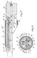
- the flanges 13a at the ends of the channel section shaped housing 13 in Figure 5 are removed in order to allow insertion of closing end blocks 14; also, holes 15 are drilled through the blocks 14 and the housing 13 at the ends thereof to permit passage of screws 16.
- Hole 17 provided in the housing member 13 is designed for passage of the mushroom-shaped short feed pipe connector 18.
- On the bottom of housing member 13 is laid a bladder 19 with the mushroom head of the connector 18 inserted into a hole made in the bladder's wall.
- the stem 18a of the connector 18 is introduced into hole 17 and secured to the housing member 13 by means of locknut 20, pressing the bladder between the head of connector 18 and the bottom of the housing member 13 and positively sealing the hole in the bladder.
- a pin valve (not shown) of the type disclosed in the above mentioned Applicant's U.S. Patent can be provided in the connector 18 in order to prevent that in case of failure of one bladder, the other bladders are deflated.
- Above the bladder in the housing member 13 is positioned a T-shaped expanding shoe 21 which is introduced through either end of the housing.
- the T-shape of the shoe provides a shoulder thereof. Closing of both ends of the bladder is obtained by means of clamping blocks 14 which press the bladder between themselves and the bottom of housing member 13 as visible in the drawing. Blocks 14 are held in this position by pins 22.
- the complete expanding device unit or assembly shown in Figure 1, and the relevant sectional views, can be inflated through the stem of the connector 18.
- Figure 6 shows shaft body 23 with U-shaped slots 24 machined on its periphery. These slots have a recess 25 designed to receive locknut 20, as well as holes 26 designed to contain the stem of the connector 18. Radial holes 26 converge toward the shaft center and lead into blind hole 27 drilled axially into the shaft at one end thereof and connecting said holes to each other.
- the expanding devices illustrated in Figure 1 are inserted into the U-shaped slots in shaft 23 and secured to it by means of screws 16 which are tightened into holes 28 drilled into the bottom of the U-shaped slots.
- self-adhesive tape may be applied between the bottom of U-shaped slot and the expanding element shown in Figure 1.
- the seal between the stem of connector 18 and holes 26 is obtained by means of sealing element, such as an O-ring 29, previously inserted in the appropriate groove on the stem of connector 18.
- sealing element such as an O-ring 29
- a fluid under pressure such as compressed air
- Figures 6 and 8 show shafts equipped with three expanding devices, which obviously can be used in a larger or smaller number.
- the shaft is shown locked inside a tubular core 31.
Landscapes
- Winding Of Webs (AREA)
Claims (4)
Applications Claiming Priority (2)
| Application Number | Priority Date | Filing Date | Title |
|---|---|---|---|
| IT28996/78A IT1100972B (it) | 1978-10-23 | 1978-10-23 | Albero con elementi ad espansione fluido dinamica per il fissaggio di |
| IT2899678 | 1978-10-23 |
Publications (2)
| Publication Number | Publication Date |
|---|---|
| EP0010266A1 EP0010266A1 (de) | 1980-04-30 |
| EP0010266B1 true EP0010266B1 (de) | 1983-03-16 |
Family
ID=11225523
Family Applications (1)
| Application Number | Title | Priority Date | Filing Date |
|---|---|---|---|
| EP79103930A Expired EP0010266B1 (de) | 1978-10-23 | 1979-10-12 | Durch den Druck eines Strömungsmittels aufspreizbare Vorrichtung für aufspreizbare Wellen zum Festhalten von Wickelhülsen für Papier, Kunststoff, Gewebe oder dgl. und aufspreizbare Welle, bei der solche Vorrichtungen verwendet werden |
Country Status (4)
| Country | Link |
|---|---|
| US (1) | US4771963A (de) |
| EP (1) | EP0010266B1 (de) |
| DE (1) | DE2965040D1 (de) |
| IT (1) | IT1100972B (de) |
Families Citing this family (18)
| Publication number | Priority date | Publication date | Assignee | Title |
|---|---|---|---|---|
| NL8102815A (nl) * | 1981-06-11 | 1983-01-03 | Tevopharm Schiedam Bv | As met middelen voor het daarop vastzetten van een haspel, rol materiaal of soortgelijk voorwerp. |
| EP0262152A4 (de) * | 1985-12-23 | 1989-02-02 | Frederick P Kann | Tragewelle für hohlzylinder. |
| US5372331A (en) * | 1993-06-15 | 1994-12-13 | Tidland Corporation | Expansible shaft for roll core |
| IT1269710B (it) * | 1994-02-01 | 1997-04-15 | Ies Srl | Albero espandibile ad azionamento pneumatico con mezzi meccanici di precentraggio per il supporto di bobine e simili |
| US5509618A (en) * | 1994-06-14 | 1996-04-23 | Klimex, Inc. | Air shaft |
| US5490640A (en) * | 1994-08-10 | 1996-02-13 | Tidland Corporation | Torque-actuated expansible shaft assembly for roll core |
| US6299179B1 (en) | 1995-03-22 | 2001-10-09 | R. S. R. Adtec Ltd. | Fluid actuated chuck |
| US6196494B1 (en) * | 1998-10-08 | 2001-03-06 | Goldenrod Corporation | Expanding shaft |
| US6079662A (en) * | 1999-03-31 | 2000-06-27 | Tidland Corporation | Slip shaft assembly having core axial position fixing mechanism |
| DE102005031265A1 (de) * | 2005-07-05 | 2007-01-18 | Sms Demag Ag | Spreizbarer Haspeldorn |
| US7896048B2 (en) * | 2006-11-08 | 2011-03-01 | Bridgestone Americas Tire Operations, Llc | Chucks and use in processing toroidal structures |
| DE102008030145A1 (de) * | 2008-06-27 | 2009-12-31 | Sms Siemag Aktiengesellschaft | Verfahren und Vorrichtung zum Aufwickeln von Metallband |
| IT1395993B1 (it) * | 2009-08-03 | 2012-11-09 | Perini Fabio Spa | "mandrino di avvolgimento per la produzione di rotoli di materiale nastriforme" |
| US9925734B2 (en) * | 2011-04-20 | 2018-03-27 | Cmd Corporation | Method and apparatus for making bags |
| US20120286087A1 (en) * | 2011-05-11 | 2012-11-15 | Jose Antonio Alvarez Tapia | Spindle adapter |
| CN104495527A (zh) * | 2014-11-24 | 2015-04-08 | 江门市蓬江区华龙包装材料有限公司 | 一种气胀轴键条定位装置 |
| CN111674139A (zh) * | 2020-05-19 | 2020-09-18 | 海宁高卓新材料股份有限公司 | 超细纤维无纺布基底复合面料涂覆涨紧装置 |
| CN114043511A (zh) * | 2021-11-30 | 2022-02-15 | 伯朗特机器人股份有限公司 | 分排胀取型装箱治具、装箱机器人及其取料装箱方法 |
Family Cites Families (13)
| Publication number | Priority date | Publication date | Assignee | Title |
|---|---|---|---|---|
| DE1047002B (de) * | 1956-01-20 | 1958-12-18 | Goebel Gmbh Maschf | Wickelwelle fuer Material-, insbesondere Papierbahnen |
| US3233341A (en) * | 1962-01-08 | 1966-02-08 | Jr William P Exton | Method of and apparatus for the direction of the placement of objects |
| US3214109A (en) * | 1963-06-12 | 1965-10-26 | Amals Gjuteri Och Mek Nerkstad | Drive spindle |
| US3286987A (en) * | 1964-09-04 | 1966-11-22 | Raymond C Bridges | Hydraulic clamping and tensioning means for saw blades |
| SE306469B (de) * | 1968-02-27 | 1968-11-25 | Aeroshaft Ab | |
| US3493189A (en) * | 1968-03-21 | 1970-02-03 | Inta Roto Machine Co Inc The | Expansible mandrel |
| US3592405A (en) * | 1969-10-09 | 1971-07-13 | Michael M Young | Pneumatically expansible mandrel |
| AU2049170A (en) * | 1970-07-13 | 1972-03-30 | Ab Amala Gjuteri & Mekaniska Verkstad | An improved drive spindle |
| FI53293C (fi) * | 1971-07-02 | 1978-04-10 | Giovanni Gattrugeri | Expansionsaxel |
| SE377319B (de) * | 1972-05-19 | 1975-06-30 | Aero Shaft Ab | |
| FR2348142A1 (fr) * | 1976-04-15 | 1977-11-10 | Bacher Christian | Dispositif de fixation amovible pour un support tubulaire |
| DE2655935C2 (de) * | 1976-12-10 | 1983-10-20 | Frank'sche Eisenwerke Ag, 6340 Dillenburg | Aufspreizbare Vorrichtung zum Befestigen von rohrförmigen Wickelhülsen auf Spindeln |
| US4147312A (en) * | 1977-09-22 | 1979-04-03 | Great Lakes Industries, Inc. | Gas-liquid hydraulic expandable chucks and shafts |
-
1978
- 1978-10-23 IT IT28996/78A patent/IT1100972B/it active
-
1979
- 1979-10-12 EP EP79103930A patent/EP0010266B1/de not_active Expired
- 1979-10-12 US US06/084,050 patent/US4771963A/en not_active Expired - Lifetime
- 1979-10-12 DE DE7979103930T patent/DE2965040D1/de not_active Expired
Also Published As
| Publication number | Publication date |
|---|---|
| IT1100972B (it) | 1985-09-28 |
| DE2965040D1 (en) | 1983-04-21 |
| US4771963A (en) | 1988-09-20 |
| IT7828996A0 (it) | 1978-10-23 |
| EP0010266A1 (de) | 1980-04-30 |
Similar Documents
| Publication | Publication Date | Title |
|---|---|---|
| EP0010266B1 (de) | Durch den Druck eines Strömungsmittels aufspreizbare Vorrichtung für aufspreizbare Wellen zum Festhalten von Wickelhülsen für Papier, Kunststoff, Gewebe oder dgl. und aufspreizbare Welle, bei der solche Vorrichtungen verwendet werden | |
| EP0189417B1 (de) | Manschette, beispielsweise zum erzeugen und aufrechterhalten flüssigkeits- und gasleerer zonen in bestimmten bereichen des körpers | |
| US4026491A (en) | Winder drums for strip slitting lines | |
| US3053467A (en) | Expansible shaft | |
| US4317577A (en) | Rotary expandable tool with hydraulic internal intensifier | |
| KR920700377A (ko) | 파이프 보수방법 및 그 장치 | |
| US3510082A (en) | Pneumatic chuck | |
| SU795511A3 (ru) | Устройство дл удержани трубНА СТОлЕ POTOPA буРОВОй уСТАНОВКи | |
| US4427102A (en) | Fluid engaged and spring returned fan clutch | |
| CZ135197A3 (en) | Device with air-operated working cylinder | |
| US2270549A (en) | Control valve for fluid operated devices | |
| EP0132913A1 (de) | Membran- oder Kolbenpumpe | |
| US3012574A (en) | Fluid conductor and take-off apparatus | |
| US5469940A (en) | Rodless cylinder unit with brake | |
| US2752175A (en) | Shaft seal | |
| US2972464A (en) | Flexible conduit valve | |
| RU96120147A (ru) | Устройство для компенсации давления | |
| US4467977A (en) | Expanding headpiece for reels in general | |
| US5009573A (en) | Variable occlusion peristaltic apparatus and method | |
| US2945667A (en) | Flexible seal for valves | |
| US3473640A (en) | Drive shaft with inflatable tube coupling | |
| US4944468A (en) | Expandable roll spindles with integral directional control valve | |
| US3394902A (en) | Inflatable mandrel | |
| US3298626A (en) | Expansible mandrel | |
| US2845146A (en) | Expander tube brake structure |
Legal Events
| Date | Code | Title | Description |
|---|---|---|---|
| PUAI | Public reference made under article 153(3) epc to a published international application that has entered the european phase |
Free format text: ORIGINAL CODE: 0009012 |
|
| AK | Designated contracting states |
Designated state(s): CH DE FR GB SE |
|
| 17P | Request for examination filed |
Effective date: 19801023 |
|
| GRAA | (expected) grant |
Free format text: ORIGINAL CODE: 0009210 |
|
| AK | Designated contracting states |
Designated state(s): CH DE FR GB SE |
|
| ET | Fr: translation filed | ||
| REF | Corresponds to: |
Ref document number: 2965040 Country of ref document: DE Date of ref document: 19830421 |
|
| EAL | Se: european patent in force in sweden |
Ref document number: 79103930.8 |
|
| PGFP | Annual fee paid to national office [announced via postgrant information from national office to epo] |
Ref country code: SE Payment date: 19950929 Year of fee payment: 17 Ref country code: FR Payment date: 19950929 Year of fee payment: 17 |
|
| PGFP | Annual fee paid to national office [announced via postgrant information from national office to epo] |
Ref country code: GB Payment date: 19951003 Year of fee payment: 17 |
|
| PGFP | Annual fee paid to national office [announced via postgrant information from national office to epo] |
Ref country code: CH Payment date: 19951011 Year of fee payment: 17 |
|
| PGFP | Annual fee paid to national office [announced via postgrant information from national office to epo] |
Ref country code: DE Payment date: 19951222 Year of fee payment: 17 |
|
| PG25 | Lapsed in a contracting state [announced via postgrant information from national office to epo] |
Ref country code: GB Effective date: 19961012 |
|
| PG25 | Lapsed in a contracting state [announced via postgrant information from national office to epo] |
Ref country code: SE Effective date: 19961013 |
|
| PG25 | Lapsed in a contracting state [announced via postgrant information from national office to epo] |
Ref country code: CH Effective date: 19961031 |
|
| GBPC | Gb: european patent ceased through non-payment of renewal fee |
Effective date: 19961012 |
|
| REG | Reference to a national code |
Ref country code: CH Ref legal event code: PL |
|
| PG25 | Lapsed in a contracting state [announced via postgrant information from national office to epo] |
Ref country code: FR Effective date: 19970630 |
|
| PG25 | Lapsed in a contracting state [announced via postgrant information from national office to epo] |
Ref country code: DE Effective date: 19970701 |
|
| EUG | Se: european patent has lapsed |
Ref document number: 79103930.8 |
|
| REG | Reference to a national code |
Ref country code: FR Ref legal event code: ST |
|
| PLBE | No opposition filed within time limit |
Free format text: ORIGINAL CODE: 0009261 |
|
| STAA | Information on the status of an ep patent application or granted ep patent |
Free format text: STATUS: NO OPPOSITION FILED WITHIN TIME LIMIT |