EP0010082A1 - Device for sealing the tap hole of a metallurgical vessel - Google Patents
Device for sealing the tap hole of a metallurgical vessel Download PDFInfo
- Publication number
- EP0010082A1 EP0010082A1 EP79890038A EP79890038A EP0010082A1 EP 0010082 A1 EP0010082 A1 EP 0010082A1 EP 79890038 A EP79890038 A EP 79890038A EP 79890038 A EP79890038 A EP 79890038A EP 0010082 A1 EP0010082 A1 EP 0010082A1
- Authority
- EP
- European Patent Office
- Prior art keywords
- closure body
- tap hole
- diameter
- gas line
- slag
- Prior art date
- Legal status (The legal status is an assumption and is not a legal conclusion. Google has not performed a legal analysis and makes no representation as to the accuracy of the status listed.)
- Granted
Links
- 238000007789 sealing Methods 0.000 title 1
- 239000002893 slag Substances 0.000 claims abstract description 13
- 239000002184 metal Substances 0.000 claims abstract description 3
- 229910052751 metal Inorganic materials 0.000 claims abstract description 3
- 229910001060 Gray iron Inorganic materials 0.000 claims description 4
- 230000014759 maintenance of location Effects 0.000 abstract description 3
- 239000007789 gas Substances 0.000 description 10
- 239000003570 air Substances 0.000 description 6
- 229910000831 Steel Inorganic materials 0.000 description 5
- 239000010959 steel Substances 0.000 description 5
- XKRFYHLGVUSROY-UHFFFAOYSA-N Argon Chemical compound [Ar] XKRFYHLGVUSROY-UHFFFAOYSA-N 0.000 description 2
- IJGRMHOSHXDMSA-UHFFFAOYSA-N Atomic nitrogen Chemical compound N#N IJGRMHOSHXDMSA-UHFFFAOYSA-N 0.000 description 2
- 238000001816 cooling Methods 0.000 description 2
- 238000004519 manufacturing process Methods 0.000 description 2
- 229910052786 argon Inorganic materials 0.000 description 1
- 238000005266 casting Methods 0.000 description 1
- 238000000034 method Methods 0.000 description 1
- 229910052757 nitrogen Inorganic materials 0.000 description 1
- 238000012805 post-processing Methods 0.000 description 1
- 238000010079 rubber tapping Methods 0.000 description 1
- 238000000926 separation method Methods 0.000 description 1
Images

Classifications
-
- C—CHEMISTRY; METALLURGY
- C21—METALLURGY OF IRON
- C21C—PROCESSING OF PIG-IRON, e.g. REFINING, MANUFACTURE OF WROUGHT-IRON OR STEEL; TREATMENT IN MOLTEN STATE OF FERROUS ALLOYS
- C21C5/00—Manufacture of carbon-steel, e.g. plain mild steel, medium carbon steel or cast steel or stainless steel
- C21C5/28—Manufacture of steel in the converter
- C21C5/42—Constructional features of converters
- C21C5/46—Details or accessories
- C21C5/4653—Tapholes; Opening or plugging thereof
-
- B—PERFORMING OPERATIONS; TRANSPORTING
- B22—CASTING; POWDER METALLURGY
- B22D—CASTING OF METALS; CASTING OF OTHER SUBSTANCES BY THE SAME PROCESSES OR DEVICES
- B22D2/00—Arrangement of indicating or measuring devices, e.g. for temperature or viscosity of the fused mass
- B22D2/001—Arrangement of indicating or measuring devices, e.g. for temperature or viscosity of the fused mass for the slag appearance in a molten metal stream
-
- B—PERFORMING OPERATIONS; TRANSPORTING
- B22—CASTING; POWDER METALLURGY
- B22D—CASTING OF METALS; CASTING OF OTHER SUBSTANCES BY THE SAME PROCESSES OR DEVICES
- B22D41/00—Casting melt-holding vessels, e.g. ladles, tundishes, cups or the like
- B22D41/14—Closures
-
- F—MECHANICAL ENGINEERING; LIGHTING; HEATING; WEAPONS; BLASTING
- F27—FURNACES; KILNS; OVENS; RETORTS
- F27D—DETAILS OR ACCESSORIES OF FURNACES, KILNS, OVENS, OR RETORTS, IN SO FAR AS THEY ARE OF KINDS OCCURRING IN MORE THAN ONE KIND OF FURNACE
- F27D3/00—Charging; Discharging; Manipulation of charge
- F27D3/15—Tapping equipment; Equipment for removing or retaining slag
- F27D3/1509—Tapping equipment
- F27D3/1536—Devices for plugging tap holes, e.g. plugs stoppers
Definitions
- a device for closing the tap hole of a metallurgical vessel in which an insertable into the tap hole, with respect to the tap hole wall leaving an annular gap and containing a compressed gas line, is provided, which has a tapering opening for the compressed gas line Has outer jacket.
- Such a device is used to make a separation of metal and slag when tapping, the known device is particularly easy to use and can be used repeatedly, u. even if the lining of the tap hole is already subject to wear.
- the closure body is designed as a truncated cone, on the mouth side of which a cylindrical extension is provided. This device has been in use in small converters for a long time. Difficulties arose when an attempt was made to use this device for large converters as well, with rapid wear and tear caused by the much higher heat exposure of a large converter.
- the invention aims to improve the known device, u. in the respect that an application also with Large converters with a long shelf life are guaranteed, with a better slag retention effect - corresponding to the higher slag bath height of a large converter - to be achieved.
- the manufacturing costs of the closure body, which is a wearing part, should also be kept as low as possible.
- the outer jacket of the closure body is formed by a spherical cap-shaped surface which merges into a frustoconical surface, the height of the truncated cone being at least 1 times and at most 2.5 times the diameter of the mouth side
- the outlet opening of the compressed gas line is and. opening angle of the truncated cone is at least 15 and at most 70 0 .
- a particularly high durability results when the closure body consists of gray cast iron.
- Fig. 1 shows a schematically illustrated section through the converter during the casting of a molten steel.
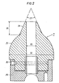
- Fig. 2 shows a section through the closure body along its axis on an enlarged scale.
- molten steel 2 In the converter vessel designated 1 there is the molten steel 2 with the slag layer 3 floating thereon.
- the steel flows through the tap hole 4 into the ladle 5 located below.
- a closure body 7 fastened to a swivel arm 6 serves to close the pressurized gas line 8 is connected.
- the swivel arm 6 is articulated on the outer jacket 9 of the fresh vessel 1 and is connected by means of a pressure medium cylinder 10 with a toothed rack which can be actuated in both directions and which is attached to the outer jacket of the vessel
- the tap hole is closed as follows: as soon as the steel has flowed into the ladle 5, the slag 3 flows out through the tap hole 4.
- the solenoid valve 21 is opened, whereby the pressure medium cylinder 10 brings the swivel arm 6 into the closed position shown in dashed lines in FIG. 1.
- the solenoid valve 22 of the supply line of the closure body is actuated, whereby the closure body, which in the pivoted-back position shown in FIG. 1 is subjected to a partial pressure of the compressed gas for the purpose of cooling, is subjected to the full pressure of the compressed gas.
- the outflowing compressed gas causes air to be drawn in through the annular gap 13, indicated by arrows, according to the injector principle.
- the slag is pushed back into the fresh container by the compressed gas air flow and can then be poured into its own slag container.
- the compressed gas can e.g. Compressed air, argon or nitrogen can be used.
- the closure body 7 which is made of gray cast iron, has an outer jacket which is formed by a spherical (spherical) surface 23 which merges into a frustoconical surface 24 on the mouth side.
- the height 25 of the frustoconical surface is approximately 1.4 times the diameter 26 of the outlet-side outlet opening of the compressed gas line, and the opening angle 27 of the truncated cone is approximately 47 °.
- the diameter 26 is approximately one third of the diameter 31 of the tap hole 4; the spherical surface 23 of the closure body 7 has a diameter 32 which is approximately 1.5 times the tap hole diameter 31.
- closure body 7 Due to the specially designed shape of the closure body 7, a particularly high durability is achieved even with the highest heat load. Furthermore, this form improves the slag retention effect, ie only less compressed air is required to retain the slag with the closure body according to the invention.
- the closure body is also inexpensive to manufacture, as long as it is manufactured using the gray cast iron process, and post-processing can be dispensed with.
- a directional joint 30 is used to precisely adjust the closure body 7 relative to the tap hole 4.
- the pressure medium cylinder To protect the pressure medium cylinder, it is installed in a heat protection box 33 which is provided with an air shower (not shown) for cooling.
- the compressed air lines are expediently supplied via the support pins (not shown) of the converter vessel.
Landscapes
- Engineering & Computer Science (AREA)
- Mechanical Engineering (AREA)
- Chemical & Material Sciences (AREA)
- Manufacturing & Machinery (AREA)
- Materials Engineering (AREA)
- Metallurgy (AREA)
- Organic Chemistry (AREA)
- General Engineering & Computer Science (AREA)
- Furnace Charging Or Discharging (AREA)
- Carbon Steel Or Casting Steel Manufacturing (AREA)
- Waste-Gas Treatment And Other Accessory Devices For Furnaces (AREA)
Abstract
Bei einer Einrichtung zum Verschließen des Stichloches (4) eines metallurgischen Gefäßes (1) zwecks Trennung von Metall (2) und Schlacke (3) ist ein in das Stichlock (4) einsetzbarer, gegenüber der Stichlochwandung einen Ringspalt (13) freilassender und eine Druckgasleitung (8) enthaltender Verschlußkörper (7) vorgesehen, der einen sich zur Mündung der Druckgasleitung verjüngenden Außenmantel aufweist. Um diese Einrichtung auch bei Großkonvertern verwenden zu können und um insbesondere den Schlacken-Rückhalteeffekt dieser Einrichtung zu verbessern, wird der Außenmantel des Verschlukörpers (7) von einer kugelkalottenförmigen Fläche (23), die in eine kegelstumpfförmige Fläche (24) mündungsseitig übergeht, gebildet, wobei die Höhe (25) des Kegelstumpfes mindestens das 1-fache und höchstens das 2,5-fache des Durchmessers (26) der mündungsseitigen Austrittsöffnung der Druckgasleitung (8) beträgt und der öffnungswinkel (27) des Kegelstumpfes mindestens 15 und höchstens 70° beträgt.In the case of a device for closing the tap hole (4) of a metallurgical vessel (1) for the purpose of separating metal (2) and slag (3), an annular gap (13) and a pressurized gas line can be inserted into the tap lock (4) (8) containing closure body (7) is provided which has an outer jacket tapering to the mouth of the compressed gas line. In order to be able to use this device also with large converters and in particular to improve the slag retention effect of this device, the outer jacket of the closure body (7) is formed by a spherical cap-shaped surface (23) which merges into a frustoconical surface (24) on the mouth side, wherein the height (25) of the truncated cone is at least 1 and at most 2.5 times the diameter (26) of the outlet-side outlet opening of the compressed gas line (8) and the opening angle (27) of the truncated cone is at least 15 and at most 70 ° .
Description
Nach der DE-OS 26 39 712 ist eine Einrichtung zum Verschließen des Stichloches eines metallurgischen Gefäßes vorgesehen, bei der ein in das Stichloch einsetzbarer, gegenüber der Stichlochwandung einen Ringspalt freilassender und eine Druckgasleitung enthaltender Verschlußkörper vorgesehen ist, der einen sich zur Mündung der Druckgasleitung verjüngenden Außenmantel aufweist.According to DE-OS 26 39 712, a device for closing the tap hole of a metallurgical vessel is provided, in which an insertable into the tap hole, with respect to the tap hole wall leaving an annular gap and containing a compressed gas line, is provided, which has a tapering opening for the compressed gas line Has outer jacket.
Eine solche Einrichtung dient dazu, eine Trennung von Metall und Schlacke beim Abstich vornehmen zu können, wobei die bekannte Einrichtung besonders einfach handzuhaben ist und wiederholt Verwendung finden kann, u. zw. auch dann, wenn die Ausmauerung des Stichloches bereits einem Ver- .schleiß unterlegen ist. Bei der bekannten Einrichtung ist der Verschlußkörper als Kegelstumpf ausgebildet, an dem mündungsseitig ein zylindrischer Fortsatz vorgesehen ist. Diese Einrichtung ist bei Kleinkonvertern seit längerer Zeit zufriedenstellend im Einsatz. Schwierigkeiten traten auf, als man versuchte, diese Einrichtung auch für Großkonverter zu verwenden, wobei ein,rascher Verschleiß, verursacht durch die wesentlich höhere Wärmeeinwirkung eines Großkonverters, auftrat.Such a device is used to make a separation of metal and slag when tapping, the known device is particularly easy to use and can be used repeatedly, u. even if the lining of the tap hole is already subject to wear. In the known device, the closure body is designed as a truncated cone, on the mouth side of which a cylindrical extension is provided. This device has been in use in small converters for a long time. Difficulties arose when an attempt was made to use this device for large converters as well, with rapid wear and tear caused by the much higher heat exposure of a large converter.
Die Erfindung bezweckt die Verbesserung der bekannten Einrichtung, u. zw. in der Hinsicht, daß ein Einsatz auch bei Großkonvertern mit langer Haltbarkeit gewährleistet ist, wobei weiters ein besserer Schlackenrückhalteeffekt - entsprechend der höheren Schlackenbadhöhe eines Großkonverters - erreicht'werden soll. Es sollen auch die Herstellungskosten des einen Verschleißteil darstellenden Verschlußkörpers so niedrig wie nur möglich gehalten werden.The invention aims to improve the known device, u. in the respect that an application also with Large converters with a long shelf life are guaranteed, with a better slag retention effect - corresponding to the higher slag bath height of a large converter - to be achieved. The manufacturing costs of the closure body, which is a wearing part, should also be kept as low as possible.
Diese Aufgaben werden erfindungsgemäß dadurch gelöst, daß der Außenmantel des Verschlußkörpers von einer kugelkalottenförmigen Fläche, die in eine kegelstumpfförmige Fläche mündungsseitig übergeht, gebildet wird, wobei die Höhe des Kegelstumpfes mindestens das 1-fache und höchstens das 2,5-fache des Durchmessers der mündungsseitigen Austrittsöffnung der Druckgasleitung beträgt und der. öffnungswinkel des Kegelstumpfes mindestens 15 und höchstens 700 beträgt.These objects are achieved in that the outer jacket of the closure body is formed by a spherical cap-shaped surface which merges into a frustoconical surface, the height of the truncated cone being at least 1 times and at most 2.5 times the diameter of the mouth side The outlet opening of the compressed gas line is and. opening angle of the truncated cone is at least 15 and at most 70 0 .
Eine besonders große Haltbarkeit ergibt sich dann, wenn der Verschlußkörper aus Grauguß besteht.A particularly high durability results when the closure body consists of gray cast iron.
Die Erfindung ist anhand der Zeichnung näher erläutert, wobei Fig. 1 einen schematisch dargestellten Schnitt durch den Konverter während des Abgießens einer Stahlschmelze zeigt. Fig. 2 stellt einen Schnitt durch den Verschlußkörper entlang seiner Achse in vergrößertem Maßstab dar.The invention is explained in more detail with reference to the drawing, in which Fig. 1 shows a schematically illustrated section through the converter during the casting of a molten steel. Fig. 2 shows a section through the closure body along its axis on an enlarged scale.
Im mit 1 bezeichneten Konvertergefäß befindet sich die Stahlschmelze 2 mit der auf ihr schwimmenden Schlackenschicht 3. Der Stahl fließt durch das Stichloch 4 in die darunter befindliche Gießpfanne 5. Zum Abschließen des Stichloches dient ein an einem Schwenkarm 6 befestigter Verschlußkörper 7, an den die Druckgasleitung 8 angeschlossen ist. Der Schwenkarm 6 ist am Außenmantel 9 des Frischgefäßes 1 angelenkt und ist mittels eines in beide Richtungen betätigbaren Druckmittelzylinders 10 mit Zahnstange, der am Außenmantel des Gefäßes befestigt ist, überIn the converter vessel designated 1 there is the
ein Ritzel 11 schwenkbar. Am Schwenkarm 6 vorgesehene Anschläge 12 verhindern, daß der Verschlußkörper das Stichloch zur Gänze abschließt; es bleibt dadurch ein ringförmiger Spalt 13 frei.a pinion 11 pivotable. Stops 12 provided on the
Das Verschließen des Stichloches geht folgendermaßen vor sich: Sobald der Stahl in die Gießpfanne 5 abgeflossen ist, fließt die Schlacke 3 durch das Stichloch 4 aus. Durch ein Verhältnispyrometer 14, durch das der ausfließende Strahl 15 beobachtet wird, erhält man beim Wechsel von Stahl zu Schlacke einen Impuls, der über einen Verstärker 16 ein Relais 17 betätigt, das daraufhin ein elektrisches Signal zu den in den Versorgungsleitungen 18, 19, 8 des Druckmittelzylinders 10 und des Verschlußkörpers 7 eingebauten Magnetventilen 20, 21, 22 sendet. Das Magnetventil 21 wird geöffnet, wodurch der Druckmittelzylinder 10 den Schwenkarm 6 in die in Fig. 1 strichliert dargestellte Schließposition bringt. Gleichzeitig wird das Magnetventil 22 der Versorgungsleitung des Verschlußkörpers betätigt, wodurch der Verschlußkörper, der in der in Fig. 1 dargestellten, zurückgeschwenkten Lage zum Zweck der Kühlung mit einem Teildruck des Druckgases beaufschlagt ist, mit dem vollen Druck des Druckgases beaufschlagt wird. Nach Erreichen der Schließstellung bewirkt das ausströmende Druckgas ein durch Pfeile angedeutetes Ansaugen von Luft durch den Ringspalt 13 nach dem Injektorprinzip. Die Schlacke wird durch den Druckgas-Luftstrom in das Frischgefäß zurückgedrängt und kann anschließend in ein eigenes Schlackengefäß abgegossen werden. Als Druckgas kann z.B. Preßluft, Argon oder Stickstoff Verwendung finden.The tap hole is closed as follows: as soon as the steel has flowed into the
Der Verschlußkörper 7, der aus Grauguß gefertigt ist, weist einen Außenmantel auf, der von einer kugelförmigen (kalottenförmigen) Fläche 23, die in eine kegelstumpfförmige Fläche 24 mündungsseitig übergeht, gebildet ist. Die Höhe 25 der kegelstumpfförmigen Fläche beträgt das etwa 1,4-fache des Durchmessers 26 der mündungsseitigen Austrittsöffnung der Druckgasleitung, und der öffnungswinkel 27 des Kegelstumpfes beträgt etwa 47°.The
Der Durchmesser 26 beträgt etwa ein Drittel des Durchmessers 31 des Stichloches 4; die kugelförmige Fläche 23 des Verschlußkörpers 7 weist etwa einen Durchmesser 32 auf, der etwa das 1,5-fache des Stichlochdurchmessers 31 beträgt.The
Durch die besonders gestaltete Form des Verschlußkörpers 7 wird eine besonders hohe Haltbarkeit auch bei höchster Wärmebelastung erreicht. Weiters wird durch diese Form der Schlackenrückhalteeffekt verbessert, d.h. zum Zurückhalten der Schlacke wird mit dem erfindungsgemäßen Verschlußkörper nur mehr weniger Druckluft benötigt. Der Verschlußkörper ist auch preisgünstig in der Herstellung, soferne er im Graugußverfahren hergestellt wird, wobei auf eine Nachbearbeitung verzichtet werden kann. Die Befestigung des Ver- schlußkörpers erfolgt mittels Wurmschrauben 28 an der am Arm 6 verstellbar montierten Halterung 29, so daß eine rasche Austauschbarkeit gesichert ist. Zur genauen Justierung des Verschlußkörpers 7 gegenüber dem Stichloch 4 dient ein Richtgelenk 30.Due to the specially designed shape of the
Zum Schutz des Druckmittelzylinders ist dieser in einem Wärmeschutzkasten 33 eingebaut, der mit einer nicht dargestellten Luftbrause zur Kühlung versehen ist. Die Zuführung der Druckluftleitungen erfolgt zweckmäßig über die nicht dargestellten Tragzapfen des Konvertergefäßes.To protect the pressure medium cylinder, it is installed in a
Claims (4)
Applications Claiming Priority (2)
| Application Number | Priority Date | Filing Date | Title |
|---|---|---|---|
| AT7147/78 | 1978-10-04 | ||
| AT714778A AT357183B (en) | 1978-10-04 | 1978-10-04 | DEVICE FOR CLOSING THE STITCH HOLE OF A METALLURGICAL VESSEL |
Publications (2)
| Publication Number | Publication Date |
|---|---|
| EP0010082A1 true EP0010082A1 (en) | 1980-04-16 |
| EP0010082B1 EP0010082B1 (en) | 1981-10-21 |
Family
ID=3593152
Family Applications (1)
| Application Number | Title | Priority Date | Filing Date |
|---|---|---|---|
| EP79890038A Expired EP0010082B1 (en) | 1978-10-04 | 1979-10-01 | Device for sealing the tap hole of a metallurgical vessel |
Country Status (7)
| Country | Link |
|---|---|
| US (1) | US4232855A (en) |
| EP (1) | EP0010082B1 (en) |
| JP (1) | JPS6032685B2 (en) |
| AT (1) | AT357183B (en) |
| CA (1) | CA1113716A (en) |
| DE (1) | DE2961076D1 (en) |
| SU (1) | SU965361A3 (en) |
Cited By (2)
| Publication number | Priority date | Publication date | Assignee | Title |
|---|---|---|---|---|
| EP0173669A2 (en) * | 1984-06-01 | 1986-03-05 | VOEST-ALPINE Aktiengesellschaft | Tiltable metallurgical vessel |
| US5105873A (en) * | 1991-09-06 | 1992-04-21 | Warmington C Edward | Casting operation emergency shut-off apparatus |
Families Citing this family (9)
| Publication number | Priority date | Publication date | Assignee | Title |
|---|---|---|---|---|
| DE2921742C2 (en) * | 1979-05-29 | 1983-09-29 | Mannesmann AG, 4000 Düsseldorf | Electric metal melting furnace with a tap opening in the bottom |
| US4679773A (en) * | 1985-09-30 | 1987-07-14 | Wunsche Edgar R | Horizontal tapping furnace and method of operation |
| AT407399B (en) * | 1999-05-21 | 2001-02-26 | Voest Alpine Ind Anlagen | METHOD FOR CLOSING AND OPENING A PUNCH HOLE IN A METALLURGICAL VESSEL |
| AT408965B (en) * | 2000-01-27 | 2002-04-25 | Voest Alpine Ind Anlagen | DEVICE FOR CLOSING A TAPPING HOLE OF A METALLURGICAL VESSEL |
| CN1323146C (en) * | 2005-06-24 | 2007-06-27 | 西北工业大学 | Borontroixide-silicon carbide self-lubricating coating and its preparing method |
| CH699511A2 (en) * | 2008-09-05 | 2010-03-15 | Stopinc Ag | Copper anode furnace with sliding closure. |
| US8715567B2 (en) * | 2010-09-23 | 2014-05-06 | Gillespie + Powers, Inc. | Furnace tap hole flow control and tapper system and method of using the same |
| DE102018216285A1 (en) * | 2018-09-25 | 2020-03-26 | Sms Group Gmbh | Slag stopper |
| CN115090841B (en) * | 2022-08-24 | 2022-11-15 | 北京科技大学 | Device for researching movement behavior of covering agent in tundish and using method |
Citations (3)
| Publication number | Priority date | Publication date | Assignee | Title |
|---|---|---|---|---|
| LU61204A1 (en) * | 1970-06-26 | 1972-03-24 | ||
| US3973761A (en) * | 1973-09-27 | 1976-08-10 | Noranda Mines Limited | Furnace tapping apparatus |
| DE2639712A1 (en) * | 1975-12-17 | 1977-06-30 | Voest Ag | PROCEDURE AND DEVICE FOR LOCKING THE TUBE HOLE OF A METALLURGICAL VESSEL |
Family Cites Families (1)
| Publication number | Priority date | Publication date | Assignee | Title |
|---|---|---|---|---|
| US4007035A (en) * | 1973-05-31 | 1977-02-08 | United States Steel Corporation | Method of using an expendable tap hole tuyere in open hearth decarburization |
-
1978
- 1978-10-04 AT AT714778A patent/AT357183B/en not_active IP Right Cessation
-
1979
- 1979-09-06 CA CA335,140A patent/CA1113716A/en not_active Expired
- 1979-09-12 US US06/074,882 patent/US4232855A/en not_active Expired - Lifetime
- 1979-10-01 DE DE7979890038T patent/DE2961076D1/en not_active Expired
- 1979-10-01 EP EP79890038A patent/EP0010082B1/en not_active Expired
- 1979-10-01 JP JP54127243A patent/JPS6032685B2/en not_active Expired
- 1979-10-01 SU SU792823407A patent/SU965361A3/en active
Patent Citations (3)
| Publication number | Priority date | Publication date | Assignee | Title |
|---|---|---|---|---|
| LU61204A1 (en) * | 1970-06-26 | 1972-03-24 | ||
| US3973761A (en) * | 1973-09-27 | 1976-08-10 | Noranda Mines Limited | Furnace tapping apparatus |
| DE2639712A1 (en) * | 1975-12-17 | 1977-06-30 | Voest Ag | PROCEDURE AND DEVICE FOR LOCKING THE TUBE HOLE OF A METALLURGICAL VESSEL |
Cited By (3)
| Publication number | Priority date | Publication date | Assignee | Title |
|---|---|---|---|---|
| EP0173669A2 (en) * | 1984-06-01 | 1986-03-05 | VOEST-ALPINE Aktiengesellschaft | Tiltable metallurgical vessel |
| EP0173669A3 (en) * | 1984-06-01 | 1987-04-29 | VOEST-ALPINE Aktiengesellschaft | Tiltable metallurgical vessel |
| US5105873A (en) * | 1991-09-06 | 1992-04-21 | Warmington C Edward | Casting operation emergency shut-off apparatus |
Also Published As
| Publication number | Publication date |
|---|---|
| EP0010082B1 (en) | 1981-10-21 |
| JPS5550417A (en) | 1980-04-12 |
| JPS6032685B2 (en) | 1985-07-30 |
| US4232855A (en) | 1980-11-11 |
| AT357183B (en) | 1980-06-25 |
| ATA714778A (en) | 1979-07-15 |
| CA1113716A (en) | 1981-12-08 |
| SU965361A3 (en) | 1982-10-07 |
| DE2961076D1 (en) | 1981-12-24 |
Similar Documents
| Publication | Publication Date | Title |
|---|---|---|
| DE2639712C2 (en) | Method and device for closing the needle hole of a metallurgical vessel | |
| EP0010082B1 (en) | Device for sealing the tap hole of a metallurgical vessel | |
| DE1300209B (en) | Pouring device | |
| DE2709727B2 (en) | Device for replacing pouring pipes on pouring vessels during continuous casting | |
| DE2919880C2 (en) | Refractory pouring pipe between pouring ladle and intermediate containers of continuous casting plants | |
| CH636784A5 (en) | COOLED CONTINUOUS CHOCOLATE WITH A DEVICE FOR GENERATING AN ELECTROMAGNETIC FORCE FIELD. | |
| DE1951447C3 (en) | Outflow slide closure for vessels for pouring metals | |
| DE1938117B2 (en) | CONTAINER WITH SLIDING LOCK FOR LIQUID MELT | |
| DE69120071T2 (en) | MULTI-STAGE SUBMERSIBLE SPOUT FOR CONTINUOUS CASTING | |
| DE3000730A1 (en) | DEVICE FOR SEPARATING SLAG FROM A MOLTING BATH | |
| EP0010535B1 (en) | Apparatus for sealing the taphole of a metallurgical vessel | |
| DE2924467A1 (en) | ROTATION VALVE | |
| DE19856343B4 (en) | Method and device for the early detection of slag flow in the shadow tube of a ladle | |
| DE1949995A1 (en) | Intermediate container (tundish) for continuous casting plants | |
| DE2361344A1 (en) | METHOD AND DEVICE FOR PASTING METAL IN A CONTINUOUSLY CASTING CLOTH | |
| EP1054067B1 (en) | Method and installation for closing and opening of a tap hole of a metallurgical vessel | |
| DE3878507T2 (en) | VESSEL AND METHOD FOR TREATING METAL MELT. | |
| DE3046967C2 (en) | Device for opening or closing the tapping hole of a Siemens-Martin furnace | |
| DE3322542C2 (en) | ||
| DE69300761T2 (en) | Inner spout made of refractory material for use in metallurgical vessels. | |
| DE8805975U1 (en) | Closing device for the tap hole of a tilting tap converter | |
| DE1483645B2 (en) | DEVICE FOR MANUFACTURING CAST BLOCKS AND METHOD OF OPERATING THE SAME | |
| AT407056B (en) | METHOD FOR CLOSING AND OPENING A STITCH HOLE OF A TILTABLE METALLURGICAL VESSEL | |
| DE2417490C3 (en) | Fireproof pair of plates for slide gates consisting of base and slide plate | |
| DE216950C (en) |
Legal Events
| Date | Code | Title | Description |
|---|---|---|---|
| PUAI | Public reference made under article 153(3) epc to a published international application that has entered the european phase |
Free format text: ORIGINAL CODE: 0009012 |
|
| AK | Designated contracting states |
Designated state(s): DE FR GB IT LU SE |
|
| 17P | Request for examination filed | ||
| ITF | It: translation for a ep patent filed | ||
| GRAA | (expected) grant |
Free format text: ORIGINAL CODE: 0009210 |
|
| AK | Designated contracting states |
Designated state(s): DE FR GB IT LU SE |
|
| REF | Corresponds to: |
Ref document number: 2961076 Country of ref document: DE Date of ref document: 19811224 |
|
| PG25 | Lapsed in a contracting state [announced via postgrant information from national office to epo] |
Ref country code: LU Free format text: LAPSE BECAUSE OF NON-PAYMENT OF DUE FEES Effective date: 19821031 |
|
| PGFP | Annual fee paid to national office [announced via postgrant information from national office to epo] |
Ref country code: FR Payment date: 19890914 Year of fee payment: 11 |
|
| PGFP | Annual fee paid to national office [announced via postgrant information from national office to epo] |
Ref country code: SE Payment date: 19890918 Year of fee payment: 11 Ref country code: DE Payment date: 19890918 Year of fee payment: 11 |
|
| PGFP | Annual fee paid to national office [announced via postgrant information from national office to epo] |
Ref country code: LU Payment date: 19890920 Year of fee payment: 11 |
|
| PGFP | Annual fee paid to national office [announced via postgrant information from national office to epo] |
Ref country code: GB Payment date: 19890930 Year of fee payment: 11 |
|
| ITTA | It: last paid annual fee | ||
| PG25 | Lapsed in a contracting state [announced via postgrant information from national office to epo] |
Ref country code: GB Effective date: 19901001 |
|
| PG25 | Lapsed in a contracting state [announced via postgrant information from national office to epo] |
Ref country code: SE Effective date: 19901002 |
|
| GBPC | Gb: european patent ceased through non-payment of renewal fee | ||
| PG25 | Lapsed in a contracting state [announced via postgrant information from national office to epo] |
Ref country code: FR Effective date: 19910628 |
|
| PG25 | Lapsed in a contracting state [announced via postgrant information from national office to epo] |
Ref country code: DE Effective date: 19910702 |
|
| REG | Reference to a national code |
Ref country code: FR Ref legal event code: ST |
|
| EUG | Se: european patent has lapsed |
Ref document number: 79890038.7 Effective date: 19910603 |
|
| PLBE | No opposition filed within time limit |
Free format text: ORIGINAL CODE: 0009261 |
|
| STAA | Information on the status of an ep patent application or granted ep patent |
Free format text: STATUS: NO OPPOSITION FILED WITHIN TIME LIMIT |