EP0010048B1 - Process and apparatus for at least partial gasification of combustible material - Google Patents
Process and apparatus for at least partial gasification of combustible material Download PDFInfo
- Publication number
- EP0010048B1 EP0010048B1 EP79400728A EP79400728A EP0010048B1 EP 0010048 B1 EP0010048 B1 EP 0010048B1 EP 79400728 A EP79400728 A EP 79400728A EP 79400728 A EP79400728 A EP 79400728A EP 0010048 B1 EP0010048 B1 EP 0010048B1
- Authority
- EP
- European Patent Office
- Prior art keywords
- enclosure
- gases
- materials
- hot gases
- recycled
- Prior art date
- Legal status (The legal status is an assumption and is not a legal conclusion. Google has not performed a legal analysis and makes no representation as to the accuracy of the status listed.)
- Expired
Links
Images

Classifications
-
- F—MECHANICAL ENGINEERING; LIGHTING; HEATING; WEAPONS; BLASTING
- F26—DRYING
- F26B—DRYING SOLID MATERIALS OR OBJECTS BY REMOVING LIQUID THEREFROM
- F26B17/00—Machines or apparatus for drying materials in loose, plastic, or fluidised form, e.g. granules, staple fibres, with progressive movement
- F26B17/10—Machines or apparatus for drying materials in loose, plastic, or fluidised form, e.g. granules, staple fibres, with progressive movement with movement performed by fluid currents, e.g. issuing from a nozzle, e.g. pneumatic, flash, vortex or entrainment dryers
- F26B17/107—Machines or apparatus for drying materials in loose, plastic, or fluidised form, e.g. granules, staple fibres, with progressive movement with movement performed by fluid currents, e.g. issuing from a nozzle, e.g. pneumatic, flash, vortex or entrainment dryers pneumatically inducing within the drying enclosure a curved flow path, e.g. circular, spiral, helical; Cyclone or Vortex dryers
-
- C—CHEMISTRY; METALLURGY
- C10—PETROLEUM, GAS OR COKE INDUSTRIES; TECHNICAL GASES CONTAINING CARBON MONOXIDE; FUELS; LUBRICANTS; PEAT
- C10B—DESTRUCTIVE DISTILLATION OF CARBONACEOUS MATERIALS FOR PRODUCTION OF GAS, COKE, TAR, OR SIMILAR MATERIALS
- C10B49/00—Destructive distillation of solid carbonaceous materials by direct heating with heat-carrying agents including the partial combustion of the solid material to be treated
- C10B49/02—Destructive distillation of solid carbonaceous materials by direct heating with heat-carrying agents including the partial combustion of the solid material to be treated with hot gases or vapours, e.g. hot gases obtained by partial combustion of the charge
- C10B49/04—Destructive distillation of solid carbonaceous materials by direct heating with heat-carrying agents including the partial combustion of the solid material to be treated with hot gases or vapours, e.g. hot gases obtained by partial combustion of the charge while moving the solid material to be treated
- C10B49/08—Destructive distillation of solid carbonaceous materials by direct heating with heat-carrying agents including the partial combustion of the solid material to be treated with hot gases or vapours, e.g. hot gases obtained by partial combustion of the charge while moving the solid material to be treated in dispersed form
-
- C—CHEMISTRY; METALLURGY
- C10—PETROLEUM, GAS OR COKE INDUSTRIES; TECHNICAL GASES CONTAINING CARBON MONOXIDE; FUELS; LUBRICANTS; PEAT
- C10B—DESTRUCTIVE DISTILLATION OF CARBONACEOUS MATERIALS FOR PRODUCTION OF GAS, COKE, TAR, OR SIMILAR MATERIALS
- C10B53/00—Destructive distillation, specially adapted for particular solid raw materials or solid raw materials in special form
- C10B53/02—Destructive distillation, specially adapted for particular solid raw materials or solid raw materials in special form of cellulose-containing material
-
- C—CHEMISTRY; METALLURGY
- C10—PETROLEUM, GAS OR COKE INDUSTRIES; TECHNICAL GASES CONTAINING CARBON MONOXIDE; FUELS; LUBRICANTS; PEAT
- C10J—PRODUCTION OF PRODUCER GAS, WATER-GAS, SYNTHESIS GAS FROM SOLID CARBONACEOUS MATERIAL, OR MIXTURES CONTAINING THESE GASES; CARBURETTING AIR OR OTHER GASES
- C10J3/00—Production of combustible gases containing carbon monoxide from solid carbonaceous fuels
- C10J3/46—Gasification of granular or pulverulent flues in suspension
- C10J3/48—Apparatus; Plants
- C10J3/485—Entrained flow gasifiers
- C10J3/487—Swirling or cyclonic gasifiers
-
- C—CHEMISTRY; METALLURGY
- C10—PETROLEUM, GAS OR COKE INDUSTRIES; TECHNICAL GASES CONTAINING CARBON MONOXIDE; FUELS; LUBRICANTS; PEAT
- C10J—PRODUCTION OF PRODUCER GAS, WATER-GAS, SYNTHESIS GAS FROM SOLID CARBONACEOUS MATERIAL, OR MIXTURES CONTAINING THESE GASES; CARBURETTING AIR OR OTHER GASES
- C10J3/00—Production of combustible gases containing carbon monoxide from solid carbonaceous fuels
- C10J3/58—Production of combustible gases containing carbon monoxide from solid carbonaceous fuels combined with pre-distillation of the fuel
- C10J3/60—Processes
- C10J3/64—Processes with decomposition of the distillation products
- C10J3/66—Processes with decomposition of the distillation products by introducing them into the gasification zone
-
- C—CHEMISTRY; METALLURGY
- C10—PETROLEUM, GAS OR COKE INDUSTRIES; TECHNICAL GASES CONTAINING CARBON MONOXIDE; FUELS; LUBRICANTS; PEAT
- C10J—PRODUCTION OF PRODUCER GAS, WATER-GAS, SYNTHESIS GAS FROM SOLID CARBONACEOUS MATERIAL, OR MIXTURES CONTAINING THESE GASES; CARBURETTING AIR OR OTHER GASES
- C10J3/00—Production of combustible gases containing carbon monoxide from solid carbonaceous fuels
- C10J3/72—Other features
- C10J3/74—Construction of shells or jackets
-
- F—MECHANICAL ENGINEERING; LIGHTING; HEATING; WEAPONS; BLASTING
- F26—DRYING
- F26B—DRYING SOLID MATERIALS OR OBJECTS BY REMOVING LIQUID THEREFROM
- F26B3/00—Drying solid materials or objects by processes involving the application of heat
- F26B3/02—Drying solid materials or objects by processes involving the application of heat by convection, i.e. heat being conveyed from a heat source to the materials or objects to be dried by a gas or vapour, e.g. air
- F26B3/10—Drying solid materials or objects by processes involving the application of heat by convection, i.e. heat being conveyed from a heat source to the materials or objects to be dried by a gas or vapour, e.g. air the gas or vapour carrying the materials or objects to be dried with it
-
- C—CHEMISTRY; METALLURGY
- C10—PETROLEUM, GAS OR COKE INDUSTRIES; TECHNICAL GASES CONTAINING CARBON MONOXIDE; FUELS; LUBRICANTS; PEAT
- C10J—PRODUCTION OF PRODUCER GAS, WATER-GAS, SYNTHESIS GAS FROM SOLID CARBONACEOUS MATERIAL, OR MIXTURES CONTAINING THESE GASES; CARBURETTING AIR OR OTHER GASES
- C10J2300/00—Details of gasification processes
- C10J2300/09—Details of the feed, e.g. feeding of spent catalyst, inert gas or halogens
- C10J2300/0903—Feed preparation
- C10J2300/0909—Drying
-
- C—CHEMISTRY; METALLURGY
- C10—PETROLEUM, GAS OR COKE INDUSTRIES; TECHNICAL GASES CONTAINING CARBON MONOXIDE; FUELS; LUBRICANTS; PEAT
- C10J—PRODUCTION OF PRODUCER GAS, WATER-GAS, SYNTHESIS GAS FROM SOLID CARBONACEOUS MATERIAL, OR MIXTURES CONTAINING THESE GASES; CARBURETTING AIR OR OTHER GASES
- C10J2300/00—Details of gasification processes
- C10J2300/09—Details of the feed, e.g. feeding of spent catalyst, inert gas or halogens
- C10J2300/0913—Carbonaceous raw material
- C10J2300/0946—Waste, e.g. MSW, tires, glass, tar sand, peat, paper, lignite, oil shale
-
- C—CHEMISTRY; METALLURGY
- C10—PETROLEUM, GAS OR COKE INDUSTRIES; TECHNICAL GASES CONTAINING CARBON MONOXIDE; FUELS; LUBRICANTS; PEAT
- C10J—PRODUCTION OF PRODUCER GAS, WATER-GAS, SYNTHESIS GAS FROM SOLID CARBONACEOUS MATERIAL, OR MIXTURES CONTAINING THESE GASES; CARBURETTING AIR OR OTHER GASES
- C10J2300/00—Details of gasification processes
- C10J2300/09—Details of the feed, e.g. feeding of spent catalyst, inert gas or halogens
- C10J2300/0953—Gasifying agents
- C10J2300/0956—Air or oxygen enriched air
-
- C—CHEMISTRY; METALLURGY
- C10—PETROLEUM, GAS OR COKE INDUSTRIES; TECHNICAL GASES CONTAINING CARBON MONOXIDE; FUELS; LUBRICANTS; PEAT
- C10J—PRODUCTION OF PRODUCER GAS, WATER-GAS, SYNTHESIS GAS FROM SOLID CARBONACEOUS MATERIAL, OR MIXTURES CONTAINING THESE GASES; CARBURETTING AIR OR OTHER GASES
- C10J2300/00—Details of gasification processes
- C10J2300/18—Details of the gasification process, e.g. loops, autothermal operation
- C10J2300/1807—Recycle loops, e.g. gas, solids, heating medium, water
- C10J2300/1823—Recycle loops, e.g. gas, solids, heating medium, water for synthesis gas
-
- C—CHEMISTRY; METALLURGY
- C10—PETROLEUM, GAS OR COKE INDUSTRIES; TECHNICAL GASES CONTAINING CARBON MONOXIDE; FUELS; LUBRICANTS; PEAT
- C10J—PRODUCTION OF PRODUCER GAS, WATER-GAS, SYNTHESIS GAS FROM SOLID CARBONACEOUS MATERIAL, OR MIXTURES CONTAINING THESE GASES; CARBURETTING AIR OR OTHER GASES
- C10J2300/00—Details of gasification processes
- C10J2300/18—Details of the gasification process, e.g. loops, autothermal operation
- C10J2300/1846—Partial oxidation, i.e. injection of air or oxygen only
-
- C—CHEMISTRY; METALLURGY
- C10—PETROLEUM, GAS OR COKE INDUSTRIES; TECHNICAL GASES CONTAINING CARBON MONOXIDE; FUELS; LUBRICANTS; PEAT
- C10J—PRODUCTION OF PRODUCER GAS, WATER-GAS, SYNTHESIS GAS FROM SOLID CARBONACEOUS MATERIAL, OR MIXTURES CONTAINING THESE GASES; CARBURETTING AIR OR OTHER GASES
- C10J2300/00—Details of gasification processes
- C10J2300/18—Details of the gasification process, e.g. loops, autothermal operation
- C10J2300/1861—Heat exchange between at least two process streams
- C10J2300/1869—Heat exchange between at least two process streams with one stream being air, oxygen or ozone
-
- C—CHEMISTRY; METALLURGY
- C10—PETROLEUM, GAS OR COKE INDUSTRIES; TECHNICAL GASES CONTAINING CARBON MONOXIDE; FUELS; LUBRICANTS; PEAT
- C10J—PRODUCTION OF PRODUCER GAS, WATER-GAS, SYNTHESIS GAS FROM SOLID CARBONACEOUS MATERIAL, OR MIXTURES CONTAINING THESE GASES; CARBURETTING AIR OR OTHER GASES
- C10J2300/00—Details of gasification processes
- C10J2300/18—Details of the gasification process, e.g. loops, autothermal operation
- C10J2300/1861—Heat exchange between at least two process streams
- C10J2300/1884—Heat exchange between at least two process streams with one stream being synthesis gas
-
- Y—GENERAL TAGGING OF NEW TECHNOLOGICAL DEVELOPMENTS; GENERAL TAGGING OF CROSS-SECTIONAL TECHNOLOGIES SPANNING OVER SEVERAL SECTIONS OF THE IPC; TECHNICAL SUBJECTS COVERED BY FORMER USPC CROSS-REFERENCE ART COLLECTIONS [XRACs] AND DIGESTS
- Y02—TECHNOLOGIES OR APPLICATIONS FOR MITIGATION OR ADAPTATION AGAINST CLIMATE CHANGE
- Y02E—REDUCTION OF GREENHOUSE GAS [GHG] EMISSIONS, RELATED TO ENERGY GENERATION, TRANSMISSION OR DISTRIBUTION
- Y02E50/00—Technologies for the production of fuel of non-fossil origin
- Y02E50/10—Biofuels, e.g. bio-diesel
Definitions
- the present invention relates to a method and an apparatus for at least partial gasification by heat treatment in a stream of hot gases of fine combustible materials
- fine combustible materials here mainly covering vegetable materials and other materials, for example the urban waste, with a wide particle size ranging from dust to particles of a few centimeters.
- fine vegetable matter By way of nonlimiting examples of fine vegetable matter, mention may be made of coarsely chopped straw, coffee and peanut shells, crushed corn cobs, rice husks, etc.
- the object of the present invention is therefore to provide a process allowing the plant materials to be suspended in a uniform manner in a stream of hot gases, in order to carry out an equal heat treatment on the different particles regardless of their size.
- Combustible materials are entrained by bringing the recycled gases outside the enclosure and passing them through orifices in the peripheral wall of the enclosure.
- the present invention also aims to provide a device allowing the implementation of the method.
- a device which comprises, in accordance with the invention, a cylindrical enclosure which forms a cyclone hearth of horizontal axis, means for producing a current of hot gases in the enclosure, a recycling chamber which surrounds the enclosure, orifices formed in the peripheral wall of the enclosure separating the latter from the recycling chamber, and a recycling device supplying the recycling chamber with hot gases taken from the enclosure so as to entrain the combustible materials to treat and suspend them in the stream of hot gases produced in the enclosure, near the peripheral wall of the enclosure, by means of the recycled gases passing through the orifices of the peripheral wall of the enclosure.
- the recycled gases can also be used to cool the wall parts located at each zone exposed to the hottest gases in the enclosure.
- the hot gases reach a relatively high temperature (more than 1000 ° C)
- the cooling of the walls exposed to these temperatures by recycled gases to a temperature of about 500 to 750 ° C avoids the accumulation on these walls of sticky particles at a higher temperature.
- Another advantage lies in the fact that the recovery of part of the hot gases slows the progression in the enclosure of plant materials between the inlet and the outlet. Gasification can then, if necessary, be carried out completely without requiring a very long enclosure.
- the initial contact of the plant materials with relatively hot recycled gases 500 to 750 ° C accelerate the drying and carbonization which precede the gasification of the materials.
- the device for heat treatment of fine vegetable matter comprises at least one combustion air injector which opens into the enclosure to produce said stream of hot gases near one, or first, axial end of the latter, the inlet of the materials to be treated being located at the other, or second, axial end of the enclosure and the outlet of the products resulting from the heat treatment of the materials being located at said first end.
- the device represented in FIGS. 1 to 4 is a gasifier intended for the gasification of fine vegetable matter, for example chopped straw.
- fine vegetable matter for example chopped straw.
- many other fine vegetable materials can be treated in an apparatus according to the invention.
- the gasifier is continuously supplied with straw chopped by an apparatus (not shown) which sends straw particles ranging from dust to twigs a few centimeters, for example more than 5 centimeters, into a chute 10.
- the gasifier comprises a device 20 for feeding chopped straw, a treatment chamber 30 forming a cyclone hearth with a horizontal axis, a recycling device 40, a recycling chamber 50 surrounding the chamber 30, and a sheet metal casing 11 covered on the outside with a layer 12 of thermal insulating material and surrounding the chamber 50. Legs 19 support the gasifier.
- the supply device 20 is, for example, of the lock type and comprises a wheel 21 with paddles 22 (figs 1 and 3) which rotates in a housing 23.
- the number of paddles 22 and their angular spacing are chosen so that it there is never direct communication between a chute 10 and a passage 24 respectively upstream and downstream of the supply device.
- the pallets 22 are provided with rubber lips 25 along their edges to prevent the rotation of the wheel from being hampered by twigs remaining glued or wedged against the wall of the housing 23.
- the feed passage 24 opens substantially tangentially into the treatment chamber 30 (FIG. 3).
- the materials to be gasified enter the chamber 30 at the rear part of the latter (in the direction of travel of the treated materials) and the gases produced exit in an axial outlet passage 31 at the front of the chamber 30.
- the chamber 30 is delimited externally by a cylindrical sheet metal casing 32 with a horizontal axis.
- the chamber 30 is a hollow cylindrical housing 34 closed at the front by a radial front wall 36 in which the outlet passage 31 opens.
- Each air injector 13 comprises a tube 14 tangent, according to a generator, to the cylinder constituting the wall peripheral of the chamber 34, and of the same length.
- the pressurized air injected into the tube 14 opens almost tangentially into the chamber 34 through a series of orifices 15, arranged along a tube generator 14.
- the peripheral wall 32 of the housing 34 undergoes after this row of air injection orifices a setback. For this, it is wound at 35 on the tube 14 (fig. 4).
- a slot 16 is provided under the tube 14 and allows the recycled gases to pass.
- an angle A for example of approximately 30 °, is preferably provided between the axis of the outlet of each orifice of the injector and the tangent to the wall adjacent to this outlet.
- This angle of 30 ° and the slot 16 prevent overheating which could bring the temperature of the wall locally to a value such that the product ash would become sticky and accumulate there.
- the chamber 30 contains an axial cylindrical passage 41 which opens, at the front, into the housing 34 through an axial duct 52 provided with an adjustable flap 51.
- the passage 41 is formed by a sheet cylindrical 33 which delimits at the rear of the chamber 30, an annular housing in the rear part of which the combustible materials to be treated are introduced.
- the wall 33 has orifices 33a (shown diagrammatically on line 1), formed for example by cutting scales in the sheet 33, which make this annular housing communicate with the axial duct 41.
- the conduit 41 passes through the radial rear partition 47 of the chamber 30.
- a high-temperature vacuum fan is disposed axially outside the chamber 30, at the outlet of the conduit 41.
- the blades 43 discharge the gases sucked through the conduit 41 in passages 44 delimited longitudinally by fixed blades 45 distributed around the axis of the chambers 30 and 50.
- the passages 44 are delimited laterally by a radial partition 46 at the rear of the gasifier and by the partition 47 forming the rear wall of the rooms 30 and 50.
- Lights 48 are made in the partition 47 to communicate the passages 44 with the recycling chamber 50.
- Ports 32a (shown diagrammatically in FIG. 1) are formed, for example, by cutting scales, in the wall 32 and communicate the recycling chamber 50 with the treatment chamber 30.
- the orifices 32a are formed in the wall 32, so that the gases passing through these orifices are oriented towards the front of the gasifier. They thus favor the routing of the materials to be treated.
- a fuel air-gas mixture can be brought into the gasifier through a line 17 which passes through the rear part of the gasifier.
- the pipe 17 opens parallel to the axis of the chamber 30, inside the envelope 11.
- the gasifier works as follows:
- line 17 is supplied with a combustible gas mixture which is ignited.
- the hot gases produced enter the treatment chamber through the orifices 32a.
- this chamber is hot (700 ° C)
- combustible materials are introduced. They then undergo the successive reactions of drying, carbonization and gasification.
- the air introduced by the injectors 13 and the combustible gas produced give rise to a combustion reaction.
- the flames are established at the front of the chamber 30, in the vicinity of its internal peripheral wall and all around the axis of the chamber. A circular stream of hot gases is produced.
- the supply of fuel mixture through line 17 can be interrupted and the gasifier operates in normal mode.
- Part of the hot gases produced in the housing 34 at a temperature of approximately 1000 to 1500 ° C. is taken up in the conduit 41 through the passage 52, and is recycled by means of the fan 42.
- the recycled gases are introduced into the chamber 50 and pass through the orifices 32a.
- the recycled gases ensure the progression of the materials to be treated thanks to the orientation towards the chamber 34 of the jets of recycled gas passing through the orifices 32a and their suspension in the hot gases at the front of the gasifier.
- the “water line” phenomenon also contributes to the progression of the materials to be treated. They tend to accumulate under the feed chute 10. However, the inertial forces of rotation tend to equalize the distribution of the materials to be treated over the entire length of the cylinder constituting the peripheral wall of the chamber 30. They create a flow (“water line” phenomenon) from the rear zone of the gasifier (under the supply chute 10) to the front zone (housing 34).
- Gases are also recycled by passage of the chamber 30 in the conduit 41 through the orifices 33a. These are gases at a temperature of around 500 to 750 ° C., since they have been cooled by the endothermic drying and carbonization reaction which occurs on the materials to be treated in the rear part of the chamber 30. In this zone, the progression of the materials is slowed down by recovery of gas through the orifices 33a.
- the materials to be treated successively undergo drying, carbonization and gasification during their progression in the chamber 30.
- the gasification requires a temperature of approximately 1000 to 1500 ° C. and occurs essentially in the housing 34, while the drying and the start of decomposition requires only a temperature of 500 to 750 ° C.
- the recycled gases are a mixture of very hot gases sampled through the passage 52 and less hot gases sampled through the orifices 33a.
- the progression of the materials to be treated depends on the proportion of gases withdrawn from the housing 34. If a small quantity of very hot gases is withdrawn, this progression is slow, the temperature of the recycled gases is low and the residence time of the materials to processing in the gasification zone is relatively long.
- the gas flow through the pipe 52 is then adjusted as a function of the time necessary for gasification, the latter varying according to the materials to be treated.
- the adjustment can be made by adjusting the position of the flap 51. Being a gasifier intended for treating specific materials, the adjustment can be made once and for all by choosing a particular passage section through the conduit 52, and it is not necessary to provide a flap 51.
- the recycled gases can be used not only to ensure the progression and the suspension of the materials to be treated, but also for the cooling of the wall parts subjected to the highest temperatures. Indeed, at temperatures of 1000 to 1500 ° C, the ashes of many plant products are sticky and adhere to the hottest walls, preventing the proper functioning of the fireplace.
- the cooling of the hot walls is carried out by sweeping by means of the gases recycled through the openings 16.
- the injection of air by the injectors 13 being carried out just before the exit of the gases resulting from the gasification, it causes cracking - and therefore elimination - of the tars conveyed by these gases.
- the presence of the air inlet orifices 15 in the peripheral wall of the chamber 34 creates a sheet of flame that the particles, during their helical progression from the feed chute 10 towards the gas outlet 31 , are obliged to cross at least once. Passing through this locally very hot flame table (1500 ° C.) allows complete and rapid gasification of these particles.
- a gasifier such as described above has been made to operate satisfactorily under the following conditions: supply of chopped straw at 10% humidity in an amount equal to 300 kg / h, production of hot gases by supply of 450 Nm 3 / h of air and recycling of 6000 Nm 3 / h of gas and production of 800 Nm 3 / h of combustible gas (heat capacity of 1000 kcal / m 3 ) (Nm 3 represents the volume for a temperature brought to 0 ° C at atmospheric pressure).
- the method and apparatus according to the invention can also be used to carry out an incomplete gasification of fine combustible materials, in order to be able to recover carbonized products which are not entirely gasified.
- the temperature of the hot gases and the residence time of the materials in the treatment chamber are determined according to the target result.
- the solid carbonization products obtained are collected through a conduit 39 located at the front of the chamber 30, and at the lower part thereof. These products can then be agglomerated to obtain a fuel comparable to charcoal.
Description
La présente invention concerne un procédé et un appareil de gazéification au moins partielle par traitement thermique dans un courant de gaz chauds de matières combustibles fines, les termes «matières combustibles fines» recouvrant ici principalement les matières végétales et d'autres matières, par exemple les déchets urbains, ayant une granulométrie étendue allant de la poussière aux particules de quelques centimètres.The present invention relates to a method and an apparatus for at least partial gasification by heat treatment in a stream of hot gases of fine combustible materials, the terms “fine combustible materials” here mainly covering vegetable materials and other materials, for example the urban waste, with a wide particle size ranging from dust to particles of a few centimeters.
A titre d'exemples non limitatifs de matières végétales fines, on peut citer la paille grossièrement hachée, les coques de café et d'arachide, les rafles de maïs broyées, les balles de riz...By way of nonlimiting examples of fine vegetable matter, mention may be made of coarsely chopped straw, coffee and peanut shells, crushed corn cobs, rice husks, etc.
La légèreté et la diversité de granulométrie des matières végétales dont le traitement thermique est l'objet de la présente invention excluent l'utilisation de gazogènes connus à lit fixe ou à lit fluidisé.The lightness and diversity of grain sizes of the plant materials, the heat treatment of which is the subject of the present invention, exclude the use of known gasifiers with fixed bed or with fluidized bed.
La présente invention a alors pour but de fournir un procédé permettant de réaliser de façon uniforme la mise en suspension des matières végétales dans un courant de gaz chauds, afin d'effectuer un traitement thermique égal sur les différentes particules quelle que soit leur taille.The object of the present invention is therefore to provide a process allowing the plant materials to be suspended in a uniform manner in a stream of hot gases, in order to carry out an equal heat treatment on the different particles regardless of their size.
Ce but est atteint par un procédé selon lequel, conformément à l'invention, l'on introduit les matières combustibles à traiter dans une enceinte cylindrique à axe horizontal, l'on établit dans l'enceinte un courant de gaz chauds tournant autour de cet axe et l'on recycle une partie des gaz chauds produits pour entraîner les particules de matières à traiter et les mettre en suspension dans le courant de gaz chauds à proximité de la paroi périphérique de l'enceinte.This object is achieved by a process according to which, in accordance with the invention, the combustible materials to be treated are introduced into a cylindrical enclosure with a horizontal axis, a current of hot gases rotating around this is established in the enclosure. axis and a part of the hot gases produced is recycled to entrain the particles of material to be treated and to suspend them in the stream of hot gases near the peripheral wall of the enclosure.
Les matières combustibles sont entraînées en ramenant les gaz recyclés à l'extérieur de l'enceinte et en les faisant passer à travers des orifices de la paroi périphérique de l'enceinte.Combustible materials are entrained by bringing the recycled gases outside the enclosure and passing them through orifices in the peripheral wall of the enclosure.
La présente invention a aussi pour but de fournir un dispositif permettant la mise en oeuvre du procédé.The present invention also aims to provide a device allowing the implementation of the method.
Ce but est atteint par un dispositif qui comporte, conformément à l'invention, une enceinte cylindrique qui forme un foyer cyclone d'axe horizontal, des moyens pour produire un courant de gaz chauds dans l'enceinte, une chambre de recyclage qui entoure l'enceinte, des orifices formés dans la paroi périphérique de l'enceinte séparant celle-ci de la chambre de recyclage, et un dispositif de recyclage alimentant la chambre de recyclage en gaz chauds prélevés dans l'enceinte de manière à entraîner les matières combustibles à traiter et à les mettre en suspension dans le courant de gaz chauds produit dans l'enceinte, à proximité de la paroi périphérique de l'enceinte, au moyen des gaz recyclés passant à travers les orifices de la paroi périphérique de l'enceinte.This object is achieved by a device which comprises, in accordance with the invention, a cylindrical enclosure which forms a cyclone hearth of horizontal axis, means for producing a current of hot gases in the enclosure, a recycling chamber which surrounds the enclosure, orifices formed in the peripheral wall of the enclosure separating the latter from the recycling chamber, and a recycling device supplying the recycling chamber with hot gases taken from the enclosure so as to entrain the combustible materials to treat and suspend them in the stream of hot gases produced in the enclosure, near the peripheral wall of the enclosure, by means of the recycled gases passing through the orifices of the peripheral wall of the enclosure.
L'utilisation d'un foyer cyclone d'axe horizontal et le recyclage de gaz chauds, non seulement permettent d'atteindre le but visé par la présente invention - mise en suspension uniforme dans un courant de gaz chauds de particules fines de tailles diverses - mais encore offrent des avantages très importants.The use of a cyclone hearth with a horizontal axis and the recycling of hot gases not only make it possible to achieve the aim of the present invention - uniform suspension in a stream of hot gases of fine particles of various sizes - but still offer very significant benefits.
Ainsi, les gaz recyclés peuvent encore être utilisés pour refroidir les parties de paroi situées au niveau de chaque zone exposée aux gaz les plus chauds dans l'enceinte. Lorsque les gaz chauds atteignent une température relativement élevée (plus de 1000°C), le refroidissement des parois exposées à ces températures par des gaz recyclés à une température d'environ 500 à 750°C évite l'accumulation sur ces parois de particules collantes à une température supérieure.Thus, the recycled gases can also be used to cool the wall parts located at each zone exposed to the hottest gases in the enclosure. When the hot gases reach a relatively high temperature (more than 1000 ° C), the cooling of the walls exposed to these temperatures by recycled gases to a temperature of about 500 to 750 ° C avoids the accumulation on these walls of sticky particles at a higher temperature.
Un autre avantage réside dans le fait que la reprise d'une partie des gaz chauds ralentit la progression dans l'enceinte des matières végétales entre l'entrée et la sortie. La gazéification peut alors, le cas échéant, être effectuée de façon complète sans que cela nécessite une enceinte de grande longueur. En outre, la mise en contact initial des matières végétales avec des gaz recyclés relativement chauds (500 à 750 °C) accélèrent le séchage et la carbonisation qui précèdent la gazéification des matières.Another advantage lies in the fact that the recovery of part of the hot gases slows the progression in the enclosure of plant materials between the inlet and the outlet. Gasification can then, if necessary, be carried out completely without requiring a very long enclosure. In addition, the initial contact of the plant materials with relatively hot recycled gases (500 to 750 ° C) accelerate the drying and carbonization which precede the gasification of the materials.
Avantageusement, le dispositif de traitement thermique de matières végétales fines comporte au moins un injecteur d'air de combustion qui débouche dans l'enceinte pour produire ledit courant de gaz chauds à proximité d'une, ou première, extrémité axiale de celle-ci, l'entrée des matières à traiter étant située à l'autre, ou seconde, extrémité axiale de l'enceinte et la sortie des produits résultant du traitement thermique des matières étant située à ladite première extrémité.Advantageously, the device for heat treatment of fine vegetable matter comprises at least one combustion air injector which opens into the enclosure to produce said stream of hot gases near one, or first, axial end of the latter, the inlet of the materials to be treated being located at the other, or second, axial end of the enclosure and the outlet of the products resulting from the heat treatment of the materials being located at said first end.
D'autres particularités et avantages du procédé et du dispositif conformes à l'invention ressortiront à la lecture de la description faite ci-après, à titre indicatif mais non limitatif, en référence aux dessins joints sur lesquels:
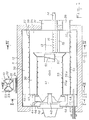
- - la fig. 1 est une vue schématique en élévation et en coupe longitudinale médiane d'un mode de réalisation d'un dispositif de traitement thermique conforme à l'invention, et,
- - les figs 2 à 4 sont des demi-vues en coupe transversales suivant respectivement les lignes II-II, III-III et IV-IV de la fig. 1.
- - fig. 1 is a schematic view in elevation and in median longitudinal section of an embodiment of a heat treatment device according to the invention, and,
- - Figs 2 to 4 are half-views in cross section along lines II-II, III-III and IV-IV respectively of fig. 1.
L'appareil représenté par les figs 1 à 4 est un gazogène destiné à la gazéification de matières végétales fines, par exemple de paille hachée. Bien entendu, comme indiqué plus haut, de nombreuses autres matières végétales fines sont susceptibles d'être traitées dans un appareil conforme à l'invention.The device represented in FIGS. 1 to 4 is a gasifier intended for the gasification of fine vegetable matter, for example chopped straw. Of course, as indicated above, many other fine vegetable materials can be treated in an apparatus according to the invention.
Le gazogène est alimenté en continu par de la paille hachée par un appareil (non représenté) qui envoie dans une goulotte 10 des particules de paille allant de la poussière aux brindilles de quelques centimètres, par exemple à plus de 5 centimètres.The gasifier is continuously supplied with straw chopped by an apparatus (not shown) which sends straw particles ranging from dust to twigs a few centimeters, for example more than 5 centimeters, into a
Le gazogène comporte un dispositif 20 d'alimentation en paille hachée, une chambre de traitement 30 formant foyer cyclone d'axe horizontal, un dispositif de recyclage 40, une chambre de recyclage 50 entourant la chambre 30, et une enveloppe 11 en tôle recouverte à l'extérieur d'une couche 12 de matériau isolant thermique et entourant la chambre 50. Des pieds 19 supportent le gazogène.The gasifier comprises a
Le dispositif d'alimentation 20 est, par exemple, du type écluse et comporte une roue 21 à palettes 22 (figs 1 et 3) qui tourne dans un logement 23. Le nombre de palettes 22 et leur espacement angulaire sont choisis pour qu'il n'y ait jamais communication directe entre une goulotte 10 et un passage 24 respectivement en amont et en aval du dispositif d'alimentation.The
Les palettes 22 sont munies de lèvres 25 en caoutchouc le long de leurs bords pour éviter que la rotation de la roue soit gênée par des brindilles restant collées ou coincées contre la paroi du logement 23.The
Le passage d'alimentation 24 débouche sensiblement tangentiellement dans la chambre de traitement 30 (fig. 3).The
Les matières à gazéifier entrent dans la chambre 30 à la partie arrière de celle-ci (dans le sens du parcours des matières traitées) et les gaz produits sortent dans un passage de sortie axial 31 à l'avant de la chambre 30.The materials to be gasified enter the
La chambre 30 est délimitée extérieurement par une enveloppe cylindrique en tôle 32 d'axe horizontal. Dans sa partie avant, la chambre 30 est un logement cylindrique creux 34 fermé à l'avant par une paroi frontale radiale 36 dans laquelle s'ouvre le passage de sortie 31.The
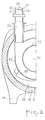
Les injecteurs d'air de combustion 13, un seul dans l'exemple illustré (figs 1 et 4), débouchent dans le logement 34. Chaque injecteur d'air 13 comporte un tube 14 tangent, selon une génératrice, au cylindre constituant la paroi périphérique de la chambre 34, et de même longueur. L'air sous pression injecté dans le tube 14 débouche presque tangentiellement dans la chambre 34 par une série d'orifices 15, disposés selon une génératrice de tube 14.The
La paroi périphérique 32 du logement 34 subit après cette rangée d'orifices d'injection d'air un décrochement. Pour ce, elle s'enroule, en 35, sur le tube 14 (fig. 4). Une fente 16 est aménagée sous le tube 14 et laisse passer les gaz recyclés.The
De plus, un angle A, par exemple d'environ 30°, est de préférence prévu entre l'axe de la sortie de chaque orifice de l'injecteur et la tangente à la paroi adjacente à cette sortie. Ainsi, la nappe de flammes produites par les divers orifices de l'injecteur n'est pas directement appliquée contre la paroi interne de la chambre au niveau de cette sortie. Cet angle de 30° ainsi que la fente 16 évitent un échauffement susceptible de porter la température de la paroi localement à une valeur telle que les cendres de produits deviendraient collantes et s'y accumuleraient.In addition, an angle A, for example of approximately 30 °, is preferably provided between the axis of the outlet of each orifice of the injector and the tangent to the wall adjacent to this outlet. Thus, the layer of flames produced by the various orifices of the injector is not directly applied against the internal wall of the chamber at this outlet. This angle of 30 ° and the
A sa partie arrière, la chambre 30 contient un passage cylindrique axial 41 qui s'ouvre, à l'avant, dans le logement 34 à travers un conduit axial 52 muni d'un volet réglable 51. Le passage 41 est formé par une tôle cylindrique 33 qui délimite à l'arrière de la chambre 30, un logement annulaire dans la partie arrière duquel les matières combustibles à traiter sont introduites. La paroi 33 présente des orifices 33a (schématisés sur la ligne 1), formés par exemple par découpage d'écailles dans la tôle 33, qui font communiquer ce logement annulaire avec le conduit axial 41.At its rear part, the
Le conduit 41 traverse la cloison arrière radiale 47 de la chambre 30. Un ventilateur aspirateur haute température est disposé axialement à l'extérieur de la chambre 30, à la sortie du conduit 41. Les pales 43 refoulent les gaz aspirés à travers le conduit 41 dans des passages 44 délimités longitudinalement par des pales fixes 45 réparties autour de l'axe des chambres 30 et 50. Les passages 44 sont délimités latéralement par une cloison radiale 46 à l'arrière du gazogène et par la cloison 47 formant la paroi arrière des chambres 30 et 50.The
Des lumières 48 sont pratiquées dans la cloison 47 pour faire communiquer les passages 44 avec la chambre de recyclage 50. Des orifices 32a (schématisés sur la fig. 1) sont formés, par exemple, par découpage d'écailles, dans la paroi 32 et font communiquer la chambre de recyclage 50 avec la chambre de traitement 30. Les orifices 32a sont pratiqués dans la paroi 32, de manière que les gaz traversant ces orifices soient orientés vers l'avant du gazogène. Ils favorisent ainsi l'acheminement des matières à traiter.
Un mélange air-gaz combustible peut être amené dans le gazogène par une conduite 17 qui traverse la partie arrière du gazogène. La conduite 17 débouche parallèlement à l'axe de la chambre 30, à l'intérieur de l'enveloppe 11.A fuel air-gas mixture can be brought into the gasifier through a
Le fonctionnement du gazogène est le suivant:The gasifier works as follows:
Au démarrage, la conduite 17 est alimentée en mélange gazeux combustible qui est enflammé. Les gaz chauds produits pénètrent dans la chambre de traitement à travers les orifices 32a. Quand cette chambre est chaude (700 °C), on introduit les matières combustibles. Elles subissent alors les réactions successives de séchage, carbonisation et gazéification.At start-up,
Lorsque la réaction de gazéification a démarré, l'air introduit par les injecteurs 13 et le gaz combustible produit donnent naissance à une réaction de combustion. Les flammes s'établissent à l'avant de la chambre 30, au voisinage de sa paroi périphérique interne et tout autour de l'axe de la chambre. Un courant circulaire de gaz chauds est produit. L'alimentation en mélange combustible à travers la conduite 17 peut être interrompue et le gazogène fonctionne en régime normal.When the gasification reaction has started, the air introduced by the
Une partie des gaz chauds produits dans le logement 34 à une température d'environ 1000 à 1500°C est reprise dans le conduit 41 à travers le passage 52, et est recyclée au moyen du ventilateur 42. Les gaz recyclés sont introduits dans la chambre 50 et passent à travers les orifices 32a. Les gaz recyclés assurent la progression des matières à traiter grâce à l'orientation vers la chambre 34 des jets de gaz recyclés passant à travers les orifices 32a et leur mise en suspension dans les gaz chauds à l'avant du gazogène.Part of the hot gases produced in the
Le phénomène de «ligne d'eau» participe aussi à la progression des matières à traiter. Elles tendent en effet à s'accumuler sous la goulotte d'alimentation 10. Cependant, les forces d'inertie de rotation tendent à égaliser la répartition des matières à traiter sur toute la longueur du cylindre constituant la paroi périphérique de la chambre 30. Elles créent un écoulement (phénomène de «ligne d'eau») de la zone arrière du gazogène (sous la goulotte d'alimentation 10) vers la zone avant (logement 34).The “water line” phenomenon also contributes to the progression of the materials to be treated. They tend to accumulate under the
Des gaz sont aussi recyclés par passage de la chambre 30 dans le conduit 41 à travers les orifices 33a. Il s'agit alors de gaz à une température d'environ 500 à 750 °C, car ils ont été refroidis par la réaction endothermique de séchage et de carbonisation qui se produit sur les matières à traiter dans la partie arrière de la chambre 30. Dans cette zone, la progression des matières est ralentie par reprise de gaz à travers les orifices 33a.Gases are also recycled by passage of the
Les matières à traiter subissent successivement un séchage, une carbonisation et une gazéification lors de leur progression dans la chambre 30. La gazéification nécessite une température d'environ 1000 à 1500°C et se produit essentiellement dans le logement 34, tandis que le séchage et le début de décomposition ne nécessitent qu'une température de 500 à 750 °C.The materials to be treated successively undergo drying, carbonization and gasification during their progression in the
Les gaz recyclés sont un mélange de gaz très chauds prélevés à travers le passage 52 et de gaz moins chauds prélevés à travers les orifices 33a. La progression des matières à traiter dépend de la proportion de gaz prélevés dans le logement 34. Si une faible quantité de gaz très chauds est prélevée, cette progression est lente, la température des gaz recyclés est peu élevée et le temps de séjour des matières à traiter dans la zone de gazéification est relativement long. Le débit de gaz à travers le conduit 52 est alors réglé en fonction du temps nécessaire à la gazéification, ce dernier variant suivant les matières à traiter. Le réglage peut être fait par ajustement de la position du volet 51. S'agissant d'un gazogène destiné à traiter des matières déterminées, le réglage peut être fait une fois pour toutes en choisissant une section de passage particulière à travers le conduit 52, et il n'est pas nécessaire de prévoir un volet 51.The recycled gases are a mixture of very hot gases sampled through the
Comme déjà indiqué, les gaz recyclés peuvent être utilisés non seulement pour assurer la progression et la mise en suspension des matières à traiter, mais aussi pour le refroidissement des parties de paroi soumises aux plus hautes températures. En effet, aux températures de 1000 à 1500°C, les cendres de nombreux produits végétaux sont collantes et adhèrent aux parois les plus chaudes, empêchant le bon fonctionnement du foyer.As already indicated, the recycled gases can be used not only to ensure the progression and the suspension of the materials to be treated, but also for the cooling of the wall parts subjected to the highest temperatures. Indeed, at temperatures of 1000 to 1500 ° C, the ashes of many plant products are sticky and adhere to the hottest walls, preventing the proper functioning of the fireplace.
Le refroidissement des parois chaudes, notamment au niveau des injecteurs d'air, est réalisé par balayage au moyen des gaz recyclés à travers les ouvertures 16.The cooling of the hot walls, in particular at the level of the air injectors, is carried out by sweeping by means of the gases recycled through the
On notera encore que l'injection d'air par les injecteurs 13 étant réalisée juste avant la sortie des gaz résultant de la gazéification, elle provoque le cracking - et donc l'élimination - des goudrons véhiculés par ces gaz. De plus, la présence des orifices d'entrée d'air 15 dans la paroi périphérique de la chambre 34 crée une nappe de flammes que les particules, au cours de leur progression hélicoïdale de la goulotte d'alimentation 10 vers la sortie des gaz 31, sont obligées de traverser au moins une fois. Le passage dans cette nappe de flammes localement très chaude (1500°C) autorise une gazéification complète et rapide de ces particules.It will also be noted that the injection of air by the
A titre d'exemple, on a pu faire fonctionner de façon satisfaisante un gazogène tel que décrit plus haut dans les conditions suivantes: alimentation en paille hachée à 10% d'humidité en quantité égale à 300 Kg/h, production de gaz chauds par fourniture de 450 Nm3/h d'air et recyclage de 6000 Nm3/h de gaz et production de 800 Nm3/h de gaz combustible (capacité calorifique de 1000 kcal/m3) (Nm3 représente le volume pour une température ramenée à 0°C à la pression atmosphérique).By way of example, a gasifier such as described above has been made to operate satisfactorily under the following conditions: supply of chopped straw at 10% humidity in an amount equal to 300 kg / h, production of hot gases by supply of 450 Nm 3 / h of air and recycling of 6000 Nm 3 / h of gas and production of 800 Nm 3 / h of combustible gas (heat capacity of 1000 kcal / m 3 ) (Nm 3 represents the volume for a temperature brought to 0 ° C at atmospheric pressure).
Dans ce qui précède, on a envisagé le cas d'un gazogène réalisant une gazéification complète.In the foregoing, we have considered the case of a gasifier carrying out a complete gasification.
Le procédé et l'appareil conformes à l'invention peuvent également être utilisés pour réaliser une gazéification incomplète des matières combustibles fines, afin de pouvoir récupérer des produits carbonisés non entièrement gazéifiés. La température des gaz chauds et le temps de séjour des matières dans la chambre de traitement sont déterminés selon le résultat visé.The method and apparatus according to the invention can also be used to carry out an incomplete gasification of fine combustible materials, in order to be able to recover carbonized products which are not entirely gasified. The temperature of the hot gases and the residence time of the materials in the treatment chamber are determined according to the target result.
Dans le cas de gazéification partielle, les produits de carbonisation solides obtenus sont recueillis à travers un conduit 39 situé à l'avant de la chambre 30, et à lapartie inférieure de celle-ci. Ces produits peuvent ensuite être agglomérés pour obtenir un combustible comparable au charbon de bois.In the case of partial gasification, the solid carbonization products obtained are collected through a
Claims (11)
Applications Claiming Priority (2)
| Application Number | Priority Date | Filing Date | Title |
|---|---|---|---|
| FR7828963 | 1978-10-11 | ||
| FR7828963A FR2438679A1 (en) | 1978-10-11 | 1978-10-11 | METHOD AND APPARATUS FOR HEAT TREATMENT OF COMBUSTIBLE MATERIALS |
Publications (2)
| Publication Number | Publication Date |
|---|---|
| EP0010048A1 EP0010048A1 (en) | 1980-04-16 |
| EP0010048B1 true EP0010048B1 (en) | 1983-07-20 |
Family
ID=9213585
Family Applications (1)
| Application Number | Title | Priority Date | Filing Date |
|---|---|---|---|
| EP79400728A Expired EP0010048B1 (en) | 1978-10-11 | 1979-10-10 | Process and apparatus for at least partial gasification of combustible material |
Country Status (4)
| Country | Link |
|---|---|
| US (1) | US4335664A (en) |
| EP (1) | EP0010048B1 (en) |
| DE (1) | DE2965942D1 (en) |
| FR (1) | FR2438679A1 (en) |
Families Citing this family (11)
| Publication number | Priority date | Publication date | Assignee | Title |
|---|---|---|---|---|
| FR2507202A1 (en) * | 1981-06-05 | 1982-12-10 | Pillard Chauffage | Horizontal cyclone furnace - employing continuous reinjection of cooled combustion gases around combustion chamber periphery |
| US4574711A (en) * | 1983-05-31 | 1986-03-11 | Christian J Vernon | Granulated solid fuel burner |
| US4709948A (en) * | 1985-08-19 | 1987-12-01 | Raychem Limited | Fibre reinforced polymeric article |
| US4632042A (en) * | 1985-10-30 | 1986-12-30 | Chang Shien F | Incinerator for the high speed combustion of waste products |
| US5068979A (en) * | 1990-01-11 | 1991-12-03 | Blaw Knox Food & Chemical Equipment Company | Apparatus for conditioning particulate material |
| DE19809067A1 (en) * | 1998-03-04 | 1999-09-09 | Nissen | Device for drying and heating dust-form and fine granular material |
| US6189463B1 (en) * | 1998-05-12 | 2001-02-20 | General Technology, Inc. | Methods and apparatus for incinerating combustible waste material such as farm animal biomass |
| RU2177977C2 (en) * | 2000-01-12 | 2002-01-10 | Антоненко Владимир Федорович | Method for thermally processing biomass |
| CH697942B1 (en) * | 2005-10-07 | 2009-03-31 | Solenia S A | Procedure and plant for the transformation of organic materials in the gas and coal. |
| DE102006013617B4 (en) * | 2006-03-22 | 2008-07-03 | Universität Kassel | biomass gasifier |
| EP2285939B1 (en) * | 2008-05-15 | 2015-04-29 | Enersol Power Llc | Method for multistage gasification |
Family Cites Families (7)
| Publication number | Priority date | Publication date | Assignee | Title |
|---|---|---|---|---|
| US2330545A (en) * | 1939-06-10 | 1943-09-28 | Edouard Le B Benoit | Desiccating apparatus |
| DE1254279B (en) * | 1962-11-23 | 1967-11-16 | Erhard Schwarze | Oil burner |
| AU588866A (en) * | 1966-05-20 | 1967-11-23 | J. Birkestrand Orville | Method and apparatus for fluidizing a. mass of discrete particles |
| US3577940A (en) * | 1969-10-27 | 1971-05-11 | Gen Electric | Incinerator |
| FR2208094B3 (en) * | 1972-11-24 | 1976-07-23 | Bazin Claudine | |
| US3838523A (en) * | 1973-03-08 | 1974-10-01 | Motch Merryweather Machinery | Multi-stage drying apparatus and method |
| US4052266A (en) * | 1973-05-11 | 1977-10-04 | Griffith Joseph W | Method and apparatus for purifying process waste emissions |
-
1978
- 1978-10-11 FR FR7828963A patent/FR2438679A1/en active Granted
-
1979
- 1979-10-10 EP EP79400728A patent/EP0010048B1/en not_active Expired
- 1979-10-10 DE DE7979400728T patent/DE2965942D1/en not_active Expired
- 1979-10-10 US US06/083,528 patent/US4335664A/en not_active Expired - Lifetime
Also Published As
| Publication number | Publication date |
|---|---|
| DE2965942D1 (en) | 1983-08-25 |
| EP0010048A1 (en) | 1980-04-16 |
| US4335664A (en) | 1982-06-22 |
| FR2438679B1 (en) | 1981-12-04 |
| FR2438679A1 (en) | 1980-05-09 |
Similar Documents
| Publication | Publication Date | Title |
|---|---|---|
| EP2627739B1 (en) | Device for the conversion of a fuel | |
| EP0010048B1 (en) | Process and apparatus for at least partial gasification of combustible material | |
| KR102537563B1 (en) | Pyrolysis device and method | |
| CH634097A5 (en) | PROCESS AND APPARATUS FOR THE TREATMENT OF A CRUSHED SOLID CARBONIZABLE PRODUCT. | |
| BE798816A (en) | FLUIDIFIED BED INSTALLATION FOR DESTRUCTION OF DETRITUS | |
| CH621571A5 (en) | ||
| EP0190168B1 (en) | Device for the gasification of waste | |
| EP0045256A2 (en) | Process and apparatus for the production of gas from bio-mass materials | |
| FR2463893A1 (en) | METHOD AND APPARATUS FOR SELF-MAINTAINING INCINERATION OF EASILY FRIABLE COMBUSTIBLE AGGLOMERES WITH HIGH WATER CONTENT | |
| EP0011037B1 (en) | Process for gasification and device for such process | |
| FR2505864A1 (en) | PROCESS FOR THE GASIFICATION OF COAL IN A DOUBLE-FLOW ROTARY OVEN | |
| EP0485255B2 (en) | Process and apparatus for the production of a solid fuel from combustible wastes | |
| CH681108A5 (en) | ||
| FR2565992A1 (en) | PROCESS AND PLANT FOR PARTIAL COMBUSTION AND GASIFICATION OF CARBONACEOUS MATERIALS, USING A PLASMA GENERATOR | |
| EP3960837A1 (en) | Fixed-bed pyro-gasification reactor with improved efficiency | |
| EP0084279B1 (en) | Process and installation for heat recuperation, in particular at the cooling of ashes | |
| BE512102A (en) | ||
| EP0076484B1 (en) | Incinerator and method of consuming by combustion, especially of vegetable waste such as hulls or husks of grains | |
| FR2803022A1 (en) | Pulverised solid fuel burner air feed uses part of air after purification for additional primary combustion and flame regulation | |
| EP0050579B1 (en) | Process and apparatus for producing cold and clean combustible gases by means of a gasification installation for solid combustibles | |
| FR2916760A1 (en) | MODULE, SYSTEM AND METHOD FOR HORIZONTAL FIXED BED BIOMASS TREATMENT | |
| FR2468836A1 (en) | Pulverised fuel combustion furnace - has air pre-heater and feed chute with blower to convey heated air and fuel to furnace | |
| OA10867A (en) | Dispositif de pyrolyse de biomasse | |
| FR2530005A1 (en) | Method and installation for drying sugar refining pulps with the use of hot gases produced by the combustion of distillery vinasses | |
| BE863953R (en) | PROCESS FOR THE CONTINUOUS PREPARATION OF CHARCOAL AND DEVICE FOR ITS IMPLEMENTATION |
Legal Events
| Date | Code | Title | Description |
|---|---|---|---|
| PUAI | Public reference made under article 153(3) epc to a published international application that has entered the european phase |
Free format text: ORIGINAL CODE: 0009012 |
|
| AK | Designated contracting states |
Designated state(s): CH DE GB IT NL SE |
|
| 17P | Request for examination filed |
Effective date: 19801010 |
|
| R17P | Request for examination filed (corrected) |
Effective date: 19801013 |
|
| RAP1 | Party data changed (applicant data changed or rights of an application transferred) |
Owner name: CENTRE NATIONAL DU MACHINISME AGRICOLE, DU GENIE R |
|
| ITF | It: translation for a ep patent filed |
Owner name: JACOBACCI & PERANI S.P.A. |
|
| GRAA | (expected) grant |
Free format text: ORIGINAL CODE: 0009210 |
|
| AK | Designated contracting states |
Designated state(s): CH DE GB IT NL SE |
|
| PG25 | Lapsed in a contracting state [announced via postgrant information from national office to epo] |
Ref country code: SE Effective date: 19830720 Ref country code: NL Effective date: 19830720 |
|
| REF | Corresponds to: |
Ref document number: 2965942 Country of ref document: DE Date of ref document: 19830825 |
|
| NLV1 | Nl: lapsed or annulled due to failure to fulfill the requirements of art. 29p and 29m of the patents act | ||
| PLBE | No opposition filed within time limit |
Free format text: ORIGINAL CODE: 0009261 |
|
| STAA | Information on the status of an ep patent application or granted ep patent |
Free format text: STATUS: NO OPPOSITION FILED WITHIN TIME LIMIT |
|
| 26N | No opposition filed | ||
| PGFP | Annual fee paid to national office [announced via postgrant information from national office to epo] |
Ref country code: CH Payment date: 19841005 Year of fee payment: 6 |
|
| PGFP | Annual fee paid to national office [announced via postgrant information from national office to epo] |
Ref country code: DE Payment date: 19881013 Year of fee payment: 10 |
|
| PG25 | Lapsed in a contracting state [announced via postgrant information from national office to epo] |
Ref country code: GB Effective date: 19891010 |
|
| PG25 | Lapsed in a contracting state [announced via postgrant information from national office to epo] |
Ref country code: CH Effective date: 19891031 |
|
| GBPC | Gb: european patent ceased through non-payment of renewal fee | ||
| REG | Reference to a national code |
Ref country code: CH Ref legal event code: PL |
|
| PG25 | Lapsed in a contracting state [announced via postgrant information from national office to epo] |
Ref country code: DE Effective date: 19900703 |