EP0010035A1 - Verfahren und Vorrichtung zum Feststellen von auf einer Wasserfläche schwimmenden Schmutzteilen - Google Patents
Verfahren und Vorrichtung zum Feststellen von auf einer Wasserfläche schwimmenden Schmutzteilen Download PDFInfo
- Publication number
- EP0010035A1 EP0010035A1 EP79400680A EP79400680A EP0010035A1 EP 0010035 A1 EP0010035 A1 EP 0010035A1 EP 79400680 A EP79400680 A EP 79400680A EP 79400680 A EP79400680 A EP 79400680A EP 0010035 A1 EP0010035 A1 EP 0010035A1
- Authority
- EP
- European Patent Office
- Prior art keywords
- electrodes
- water
- detection device
- group
- resistance
- Prior art date
- Legal status (The legal status is an assumption and is not a legal conclusion. Google has not performed a legal analysis and makes no representation as to the accuracy of the status listed.)
- Withdrawn
Links
Images

Classifications
-
- G—PHYSICS
- G01—MEASURING; TESTING
- G01N—INVESTIGATING OR ANALYSING MATERIALS BY DETERMINING THEIR CHEMICAL OR PHYSICAL PROPERTIES
- G01N27/00—Investigating or analysing materials by the use of electric, electrochemical, or magnetic means
- G01N27/02—Investigating or analysing materials by the use of electric, electrochemical, or magnetic means by investigating impedance
- G01N27/04—Investigating or analysing materials by the use of electric, electrochemical, or magnetic means by investigating impedance by investigating resistance
- G01N27/06—Investigating or analysing materials by the use of electric, electrochemical, or magnetic means by investigating impedance by investigating resistance of a liquid
Definitions
- the present invention relates to a method for detecting an element of impurity floating on the surface of a body of water, of the type according to which the resistivity is measured, at at least one point on the surface of this body of water. of a surface layer of this body of water and the position of this measuring point on the surface of this body of water is determined.
- the invention also relates to a device and an installation for implementing this method.
- this known method consists in measuring the resistivity of water only at a fixed point.
- the body of the known device is stationary and does not float.
- this known method and device do not make it possible to solve the problem of monitoring a sheet of hydrocarbon on the surface of a body of water; only the monitoring of such aquifers makes it possible, in fact, to predict its evolution and to locate the coastal zones at risk of being polluted by the aquifer.
- the invention overcomes this drawback and in particular aims to propose a method for monitoring the location and the spatial extension of a sheet of hydrocarbon.
- the method according to the invention is advantageously implemented using at least one detection device of the type comprising a body, at least two electrodes electrically isolated from one another and mounted on the body so both being able to be immersed in water and means for measuring the resistance between said electrodes, a device which, according to the invention, is characterized in that said body is capable of floating on the surface of the area d water and that it further comprises means for remotely transmitting measurement information which is a function of the value of this resistance and a position information which is a function of the position of said body on the surface of the area of water.
- the electrodes of each group are distributed over the surface of the body so that, simultaneously, an electrode of a group and an electrode of the other group are always immersed in the liquid of the body of water, whatever whatever the position of the body around its center.
- the body is spherical in shape.
- said body is made of plastic of the self-lubricating type or of polyvinyl chloride.
- the electrodes are each fixed on the body in a detachable manner and project outwards from the surface of the body, and these electrodes are chosen from sets of electrodes of different dimension (s).
- the electrodes have a surface devoid of sharp edges and which is preferably polished or chrome-plated.
- the device further comprises a radio transmitter connected to the resistance measurement means, for remotely transmitting a signal which is a function of the resistance value measured by said measurement means.
- the electrodes are arranged on a spherical surface in the manner of the black polygons arranged on certain soccer balls, the spherical surface in question being moreover the size of a ball.
- the number of electrodes and their arrangement are such that, whatever the position of the sphere, two adjacent electrodes are in contact at all times with the surface of the sea.
- the electrodes are advantageously made of materials resistant enough to corrosion by seawater: bronze, stainless steel, etc. In addition, their surface condition is particularly careful (chrome plating, polishing) so as to avoid adhesion of the product. polluting. They are preferably of cylindrical - or frustoconical - shape, preferably having no sharp edges to avoid the risk of corrosion. These electrodes are fixed in a removable manner on the body. It is therefore possible to mount on the body electrodes of a height specially chosen to allow the determination of the thickness of the oil layer in which one is interested and from which one wishes to be warned.
- the method according to the invention can be implemented using detection devices defined above, using a specific installation which is characterized, in accordance with the invention, in that it comprises at least a fixed or mobile station, of known or determinable position, located on the surface of the terrestrial globe or above this surface, this station comprising means for determining the direction of the radio emission originating from each detection device and for receiving this emission.
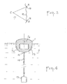
- the detection device shown in Figures 1 and 2 consists of a spherical body 1 of electrically insulating material.
- the body 1 is provided with metal electrodes 2.
- Each electrode 2 has a frustoconical shape tapering in the direction opposite to the spherical surface of the body 1.
- the electrodes 2 are divided into two groups equal in number of electrodes 2i, 2i.
- the electrodes 2i, 2i of the same group are short-circuited one another, as shown in FIG. 2.
- the body 1 provided with its electrodes 2 has a density low enough to be able to float on the surface of a body of water 3.
- Both all 2 electrodes and electrodes 2i, 2j of each group are distributed uniformly on the surface of the body 1 and the spacing between two neighboring electrodes 2 is chosen so that there are always at least two immersed electrodes each belonging to a different group, whatever or the angular position of the body 1 around its center.
- the short-circuit conductor 4 of each group of electrodes 2i, 2i is connected to a corresponding input terminal of a resistance measurement circuit 5.
- this circuit consists of a Wheatstone bridge whose output terminals 6 and 7 are each connected to a respective input 8a, 8b of a differential amplifier 8.
- the output signal from the resistance measurement circuit 5 is applied to an input of a comparator 9, the other input of which receives a reference signal of constant amplitude supplied by a generator 10.
- the comparator 9 is of the type providing at its output a signal of constant amplitude, or no signal, depending on whether the amplitude of the resistance measurement signal supplied by the circuit 5 is greater or less than the amplitude of the reference signal.
- the output signal from comparator 9 feeds a radio transmitter 11 emitting a signal of the digital type which is applied to it by a generator 12.
- This digital signal is, for example, characteristic of the detection device and therefore allows to identify the latter when several identical detection devices are used simultaneously on the same maritime region.
- the body 1 which may be constituted by a hollow plastic sphere.
- the antenna 11a of the radio transmitter 11 projects outside of body 1 ( Figure 1).
- this ballast could, for example, be constituted by a heavy element fixed to the body 1 and housed in the latter opposite the antenna lla; this ballast can also be constituted, as shown in FIG.
- the detection device which has just been described finds particular application in the detection and localization of a sheet of hydrocarbon, for example of crude oil, floating on the surface of seas or oceans.
- the electrodes 2 are made of a material resistant to corrosion by sea water such as bronze or stainless steel; they have an outer surface devoid of sharp edges and their surface condition is particularly improved, for example by chrome plating or polishing, so as to avoid adhesion of the polluting product to said electrodes 2.
- the body 1 is advantageously made of plastic material of the self-lubricating type, such as polytetrafluoroethylene (PTFE), or else of polyvinyl chloride.
- the body 1 can be formed in the form of a metal box covered with a layer of insulating material whose surface characteristics have the advantages of those of self-lubricating plastics.
- FIG. 3 shows a coast 16, two fixed stations of radio receivers A and B, placed along this coast 16, and sufficiently spaced from each other, and a detection device C placed at a point of the sea surface 17 bounded by the coast 16.
- the stations A and B and the detection device C were each represented by a single point in FIG. 3.
- Stations A and B are each provided with a very directing and orientable radio reception antenna 18.
- the stations When a sheet of oil reaches device C, the latter emits a radio wave which is received by the receivers of stations A and B. Thanks to their steerable and orientable antennas 18, the stations can determine the direction of the lines AC and BC; knowing exactly the position of points A and B, it is thus very easy to determine that of point C.
- Fixed coast stations such as A and B can be replaced by an artificial satellite fitted with devices for detecting the position of the detection devices.
- the detection devices are equipped with a responder system emitting a radio signal on reception of a radar signal, this responder being supplied by the output signal from the comparator 9.
- This system answering machine being known per se, it is not described further in the present text.
- This embodiment has the advantage of allowing the location of the devices on the surface of the body of water using a single station, which can be an airplane flying over said body of water.
- the body 1 is no longer completely spherical but its emerged part is truncated so as to offer no wind resistance.
- this device only has two electrodes 2a, 2b in the form of a circumference segment. applied against the spherical surface of the submerged part of the body; these electrodes 2a, 2b are preferably arranged in the same normally vertical plane containing the axis of symmetry la of the body.
- the method of the invention is applicable for the detection of any other impurity liquid having an electrical conductivity higher or lower than that of sea water.
Landscapes
- Chemical & Material Sciences (AREA)
- Chemical Kinetics & Catalysis (AREA)
- Electrochemistry (AREA)
- Physics & Mathematics (AREA)
- Health & Medical Sciences (AREA)
- Life Sciences & Earth Sciences (AREA)
- Analytical Chemistry (AREA)
- Biochemistry (AREA)
- General Health & Medical Sciences (AREA)
- General Physics & Mathematics (AREA)
- Immunology (AREA)
- Pathology (AREA)
- Investigating Or Analyzing Materials By The Use Of Electric Means (AREA)
- Geophysics And Detection Of Objects (AREA)
Applications Claiming Priority (2)
| Application Number | Priority Date | Filing Date | Title |
|---|---|---|---|
| FR7827374A FR2436987A1 (fr) | 1978-09-25 | 1978-09-25 | Procede et dispositif de detection d'element d'impurete surnageant a la surface d'une etendue d'eau |
| FR7827374 | 1978-09-25 |
Publications (1)
| Publication Number | Publication Date |
|---|---|
| EP0010035A1 true EP0010035A1 (de) | 1980-04-16 |
Family
ID=9212995
Family Applications (1)
| Application Number | Title | Priority Date | Filing Date |
|---|---|---|---|
| EP79400680A Withdrawn EP0010035A1 (de) | 1978-09-25 | 1979-09-25 | Verfahren und Vorrichtung zum Feststellen von auf einer Wasserfläche schwimmenden Schmutzteilen |
Country Status (2)
| Country | Link |
|---|---|
| EP (1) | EP0010035A1 (de) |
| FR (1) | FR2436987A1 (de) |
Cited By (2)
| Publication number | Priority date | Publication date | Assignee | Title |
|---|---|---|---|---|
| US4490678A (en) * | 1981-05-15 | 1984-12-25 | Licentia Patent-Verwaltungs-G.M.B.H. | Method of and an apparatus for measuring ion concentrations in solutions |
| DE3503833A1 (de) * | 1984-02-13 | 1985-08-14 | Emhart Industries, Inc., Indianapolis, Ind. | Detektoranordnung fuer stroemende medien |
Citations (4)
| Publication number | Priority date | Publication date | Assignee | Title |
|---|---|---|---|---|
| FR2168374A1 (de) * | 1972-01-17 | 1973-08-31 | Robertshaw Controls Co | |
| US3800219A (en) * | 1972-10-10 | 1974-03-26 | T Fosberg | Method and apparatus for detecting oil pollution in water |
| BE813640A (fr) * | 1974-04-12 | 1974-07-31 | Detecteur de film d'hydrocarbure pour eaux calmes et agitees. | |
| US4058802A (en) * | 1976-02-09 | 1977-11-15 | Frank Meyers | Contaminating spill detection arrangement |
Family Cites Families (1)
| Publication number | Priority date | Publication date | Assignee | Title |
|---|---|---|---|---|
| FR1399477A (fr) * | 1964-06-25 | 1965-05-14 | Dispositif indicateur sensible aux couches d'huile sur l'eau |
-
1978
- 1978-09-25 FR FR7827374A patent/FR2436987A1/fr active Granted
-
1979
- 1979-09-25 EP EP79400680A patent/EP0010035A1/de not_active Withdrawn
Patent Citations (4)
| Publication number | Priority date | Publication date | Assignee | Title |
|---|---|---|---|---|
| FR2168374A1 (de) * | 1972-01-17 | 1973-08-31 | Robertshaw Controls Co | |
| US3800219A (en) * | 1972-10-10 | 1974-03-26 | T Fosberg | Method and apparatus for detecting oil pollution in water |
| BE813640A (fr) * | 1974-04-12 | 1974-07-31 | Detecteur de film d'hydrocarbure pour eaux calmes et agitees. | |
| US4058802A (en) * | 1976-02-09 | 1977-11-15 | Frank Meyers | Contaminating spill detection arrangement |
Cited By (2)
| Publication number | Priority date | Publication date | Assignee | Title |
|---|---|---|---|---|
| US4490678A (en) * | 1981-05-15 | 1984-12-25 | Licentia Patent-Verwaltungs-G.M.B.H. | Method of and an apparatus for measuring ion concentrations in solutions |
| DE3503833A1 (de) * | 1984-02-13 | 1985-08-14 | Emhart Industries, Inc., Indianapolis, Ind. | Detektoranordnung fuer stroemende medien |
Also Published As
| Publication number | Publication date |
|---|---|
| FR2436987B1 (de) | 1982-01-22 |
| FR2436987A1 (fr) | 1980-04-18 |
Similar Documents
| Publication | Publication Date | Title |
|---|---|---|
| CA2106115A1 (fr) | Systeme de calcul d'au moins un parametre de controle de trafic de vehicules | |
| WO2005086286A2 (fr) | Antenne a depointage variable comprenant au moins un element dephaseur | |
| FR2946806A1 (fr) | Element rayonnant d'antenne multi-bande | |
| EP0776459B1 (de) | Beobachtungen von unterhalb einer unruhigen wasseroberfläche | |
| EP0035421B1 (de) | Umhüllung einer Diagraphiesonde und Verfahren zu ihrer Herstellung | |
| EP0010035A1 (de) | Verfahren und Vorrichtung zum Feststellen von auf einer Wasserfläche schwimmenden Schmutzteilen | |
| US9318808B1 (en) | Configurable electromagnetic reflector | |
| FR3009393A1 (fr) | Objet marin apte a flotter sur l'eau comprenant un dispositif d'emission et/ou de reception d'ondes electromagnetiques deployable | |
| WO2000040937A1 (fr) | Detecteur bolometrique a antenne | |
| WO2015062995A1 (fr) | Antenne radiofrequence sous-marine | |
| Kotova et al. | Oil spill detection using spaceborne SAR- A brief review | |
| EP3147676B1 (de) | Kontrollvorrichtung eines elektrischen leiters, und elektrische anlage, die eine solche vorrichtung umfasst | |
| WO2018114997A1 (fr) | Ligne destinee a etre immergee en milieu aquatique | |
| FR2462791A1 (fr) | Detecteur pour ondes submillimetriques comportant plusieurs elements a reponse non lineaire | |
| EP0053067B1 (de) | Vorrichtung zur Übertragung elektrischer Signale und zur Kodierung einer relativen Winkelposition zwischen einem rotierenden Teil und einem feststehenden Teil | |
| WO2016083590A1 (fr) | Dispositif de balisage à installer sur un mât et procédé d'installation associé | |
| EP3871001A1 (de) | Verfahren zur verwendung eines aktiven sonars mit einem breiten spektralen emissionsband und sonarsystem | |
| FR2492529A1 (fr) | Dispositif sensible destine a un appareil de detection d'une substance sur la surface d'un liquide | |
| EP2888784B1 (de) | Induktives oberflächenelement | |
| FR2475259A1 (fr) | Emetteur de signaux de detresse portatif et commutateur par inclinaison pour un tel emetteur | |
| FR2948194A1 (fr) | Systeme radar complementaire pour la detection de cibles evoluant dans un champ d'eoliennes | |
| EP0508866A1 (de) | Navigationseinrichtung zur Radardetektion | |
| EP0028566A2 (de) | Mit Meerwasser aktivierte Zelle | |
| FR2923084A1 (fr) | Diode organique electroluminescente de type vumetre. | |
| FR2656131A1 (fr) | Balise re reperage a emetteur acoustique directif pour containers de produits toxiques. |
Legal Events
| Date | Code | Title | Description |
|---|---|---|---|
| PUAI | Public reference made under article 153(3) epc to a published international application that has entered the european phase |
Free format text: ORIGINAL CODE: 0009012 |
|
| AK | Designated contracting states |
Designated state(s): BE DE GB IT NL SE |
|
| 17P | Request for examination filed | ||
| STAA | Information on the status of an ep patent application or granted ep patent |
Free format text: STATUS: THE APPLICATION IS DEEMED TO BE WITHDRAWN |
|
| 18D | Application deemed to be withdrawn |
Effective date: 19811005 |
|
| RIN1 | Information on inventor provided before grant (corrected) |
Inventor name: BARANOFF, DIMITRI |