EP0010016A1 - Actuating mechanism for moving a straight edge parallel to itself on a drawing board - Google Patents
Actuating mechanism for moving a straight edge parallel to itself on a drawing board Download PDFInfo
- Publication number
- EP0010016A1 EP0010016A1 EP79400632A EP79400632A EP0010016A1 EP 0010016 A1 EP0010016 A1 EP 0010016A1 EP 79400632 A EP79400632 A EP 79400632A EP 79400632 A EP79400632 A EP 79400632A EP 0010016 A1 EP0010016 A1 EP 0010016A1
- Authority
- EP
- European Patent Office
- Prior art keywords
- axis
- pulley
- mechanism according
- rule
- board
- Prior art date
- Legal status (The legal status is an assumption and is not a legal conclusion. Google has not performed a legal analysis and makes no representation as to the accuracy of the status listed.)
- Granted
Links
Images


Classifications
-
- B—PERFORMING OPERATIONS; TRANSPORTING
- B43—WRITING OR DRAWING IMPLEMENTS; BUREAU ACCESSORIES
- B43L—ARTICLES FOR WRITING OR DRAWING UPON; WRITING OR DRAWING AIDS; ACCESSORIES FOR WRITING OR DRAWING
- B43L13/00—Drawing instruments, or writing or drawing appliances or accessories not otherwise provided for
- B43L13/02—Draughting machines or drawing devices for keeping parallelism
- B43L13/04—Guides for rulers
- B43L13/046—Guides for rulers with cables
Definitions
- the present invention relates to a mechanism for controlling the movement of a rule parallel to itself on a drawing board or the like, of the type comprising at least two rollers or pulleys integral in rotation with an axis arranged parallel to the rule and , on two opposite sides of the board, guide elements of the cable or toothed belt type each cooperating respectively with one of the rollers or pulleys, the rule and the board being integral in translation, one of the pulleys and the other guide elements.
- a counterweight is generally mounted on the lower strand of the element.
- this counterweight is relatively bulky and, moreover, it does not provide effective balancing in all positions of the ruler and the board.
- US Patent No. 3,082,535 partially provides a solution to this problem. It describes a balancing mechanism of the rule comprising a helical spring wound around an axis and integral with the latter at one end and with a fixed support at its other end.
- This axis carries a pulley on which is wound a first cable to which is hooked one end of the rule.
- the pulley is made integral in rotation with the axis by a disengageable coupling.
- the two ends of the rule are fixed to a second cable, independent of the first, which conventionally ensures the synchronization of the movements of the two ends of the rule.
- the pulley is detached from the axis and the latter is rotated by means of a knurled button, which has the effect of modifying the tension of the spring.
- this solution has the disadvantage of requiring a balancing device separate from the movement control mechanism of the rule parallel to itself, which increases the size and the cost of the assembly.
- this balancing device could not be adapted to the control mechanism of the aforementioned type by directly mounting the spring on the axis of this mechanism and making one of its pulleys disengageable: indeed, in this case the rotation of the axis would cause that of the other pulley and therefore of the corresponding end of the rule, so that any change in the tension of the spring would cause a change in the angular position of the rule on the table.
- the invention therefore aims to achieve a control mechanism of the aforementioned type comprising, integrated therein, a balancing device of the rule which allows to adjust the balancing without changing the orientation of the rule on the board.
- the invention also aims to provide a control mechanism of the aforementioned type which makes it easy to selectively modify the orientation of the rule on the board without changing the balancing setting, and to lock the rule in any position. this on the board, and which, in the case of endless guide elements, allows to adjust the tension.
- the subject of the invention is a mechanism for controlling the movement of a rule parallel to itself on a drawing board, this mechanism comprising a rotary axis carrying at each of its ends a pulley and arranged parallel to the rule, two guide elements mounted along two opposite sides of the board and each cooperating with a pulley, the rule and the board being integral in translation, one of the pulleys and the other of the guide elements, and a device for balancing the rule comprising a torsion spring wound around the axis and one end of which is integral in rotation with said axis and the other end of which is normally fixed in rotation with respect to said axis, as well as adjustment means of the spring tension, the means for adjusting the spring tension comprising a sleeve interposed between the axis and the fixed support and to which said other end of the spring is fixed, the sleeve and the axis on the one hand and the m anchon and the support on the other hand being capable of rotating relative to each other, and retractable means
- the sleeve comprises a hollow knurled head, fitted on a flange secured to the fixed support, and locked to this flange by said retractable fastening means.
- said retractable securing means comprise a movable lock between a first position where it secures the sleeve with a flange secured to the fixed support and a second position where it locks the sleeve in rotation with one of said pulleys.
- the control mechanism comprises a device for braking the rule associated with the other pulley, said braking device comprising one. part integral with the fixed support and carrying at least one brake shoe, a skirt integral with said other pulley and surrounding said jaw, and means for selectively clamping said jaw against said skirt.
- the support of the rotary axis and of the pulleys being fixed to the board along a longitudinal edge of the latter and the guide elements being constituted by endless members each passing on a second pulley disposed in the vicinity of the other longitudinal edge of the board, said second pulleys are each associated with a device for adjusting the tension of the belt comprising an axis which carries said second pulley and which is mounted in an oblong bore of a support assembly fixed along said other longitudinal edge of the board, said bore being elongated in a plane parallel to that of the board, the adjustment device also comprising means for adjusting the position of the axis in the bore.
- Fig. 1 shows a drawing board or table 1 on which a rule 2 is mounted which can move parallel to itself over the entire surface of the board 1.
- the board or table 1 is equipped with a control which comprises two guide elements 3a and 3b, elongated, mounted on either side of the board and parallel to the lateral sides thereof.
- each of the guide elements is an endless element constituted, at least partially, by an inextensible toothed belt passing over two pulleys 4a, 5a and 4b, 5b respectively.
- the lower pulleys 4a, 4b of the two guide elements 3a, 3b are mounted to rotate freely on an axis forming part of a device 6a, 6b for adjusting the tension of the belt secured to the board 1.
- the upper pulleys 5a, 5b which are notched, are integral in rotation with one another and are mounted at the two ends of an axis 7 (Fig. 2) free to rotate inside a tubular support 8 parallel to the upper edge of the board 1.
- the upper pulley 5a over which the belt 3a passes is associated with a device 9 for balancing and adjusting the orientation of the rule 2, while the upper pulley 5b over which the other belt 3b passes is associated with a device 11 for braking the rule 2.
- the support 8 is fixed to the board 1 and is integral therewith, while the rule 2 is fixed at its two ends to the guide elements 3a, 3b and is consequently integral in translation. Any displacement of the rule 2 along the board 1 consequently causes a simultaneous displacement in translation of the two guide elements 3a, 3b, that is to say a simultaneous rotation of the two toothed pulleys 5a, 5b and the axis.
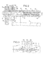
- FIG. 2 shows a first embodiment of the balancing device 9.
- a sleeve 14 which is free to rotate relative to the axis 7 thanks to the interposition of a ball bearing 16 and which., in addition, can rotate freely in the support 8.
- this sleeve 14 is fixed the end 17 of a torsion spring 18 wound around the axis 7 and having its opposite end 19 fixed on this axis 7.
- the end outside of the sleeve 14 is moreover provided with a knurled head 20, projecting outside the support 8, which is hollowed out internally and is fitted onto a flange 22 secured to the support 8.
- the flange 22 has a radial housing 23 in which is mounted a ball 24 pushed outwardly by a spring 26.
- This ball cooperates with notches formed in the internal surface of the recess 28 of the wheel 20, so as to secure in rotation the flange 22 and the head 20 of the sleeve 14.
- the notches are delimited by curved surfaces, so that an effort on the knurled head 20 makes it possible to rotate the latter relative to the flange 22 and modify the position of the sleeve 14 inside the support tube 8 and with respect to the axis 7. It is clear that such a rotation of the sleeve 14 modifies the torsion of the spring 18.
- the same balancing device can be mounted in a cable-controlled mechanism, the notched pulleys then being replaced by ordinary pulleys or by threaded rollers.
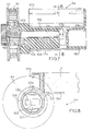
- the ends of a cable or a toothed belt constituting an endless guide element are preferably fixed to each other by means of a connecting plate 30 (Fig. 3), which is pierced with 'A central hole in which comes to fit a stud 32 secured to the rule 2.
- the stud 32 whose end has an annular groove in which is mounted an O-ring, rubber for example, 34, sufficiently elastic to be retracted inside the groove 33, can easily be inserted into the plate 30 or removed when it is desired to separate the rule 2 from the guide element 3a.
- the stud 32 is carried by a fixing block 36 in abutment against the end of the rule 2. Beyond this block 36 the stud 32 is extends inside a U-shaped profile 38, and has a threaded end on which is screwed a nut 39 which tightens a jumper 40 against the folded wings of the U-shaped profile.
- the assembly of the fixing block of the rider and the stud 32 is thus closely secured to rule 2 and this assembly can be separated from the joining plate 30 by removing the stud 32 from the hole of the latter.
- the ruler is free and can be lifted from the drawing board, for example for placing a sheet or for any other reason.
- the stud 32 is then easily reintroduced into the plate 30, the seal 34. emerging : elastically from the groove 33 and ensuring the locking of the assembly.
- the support of the rotary axis and of the pulleys 6 is fixed on the drawing board 1, while the elements of guidance are integral in translation with rule 2, but it is obvious that the balancing device of the invention can also be mounted on a mechanism operating in reverse, that is to say in which the pulleys and the 'rotary axis which connects them are integral in translation with the rule 2, while the guide elements are integral with the board 1.
- the sleeve 14 can be interposed between a rotary axis 10 mounted inside the U-shaped section 38 integral with the rule 2, the knurled head 20 projecting at one end of this section 38, between the latter and the corresponding toothed pulley.
- the immobilization of the rule can then be obtained in any desired position, as previously described.
- the toothed belt can, of course, be fixed at each of its ends on a junction plate pierced with a cooperation hole with a fixing stud, but in this case the stud is secured to the board.
- this arrangement facilitates the possible replacement of the belt or the cable and makes it possible to tension the guide element. Indeed, it is no longer necessary to provide a clearance allowing a lifting of the rule since the latter can be made independent of one or the other of the guide elements at will, by a simple removal of the stud 32.
- the accuracy of the synchronization of the displacements of the two ends of the rule is, consequently, reinforced.
- Figs. ' 4 and 5 illustrate a second embodiment of the balancing device, designated by the reference 109 which can be substituted for the balancing device 9 of FIG. 2.
- the axis 7 has a polygonal section and a cylindrical sleeve 111 of diameter greater than the most large dimension in section of the axis 7 is rotatably mounted around it.
- the sleeve 111 is integral at one of its ends with a radial flange 112 having projecting on one face a cylindrical extension 113 delimiting with the flange 112 a housing in which is received a ball bearing 114.
- the flange 112 ends at its periphery by a ring 115 arranged on the same side of the flange 112 as the extension 113, that is to say on the side opposite to the fixed support 8.
- a slot 116 In the ring 115 and the flange 112 is formed a slot 116 through which can move a lock 117 whose role will be explained later.
- a helical torsion spring 118 On the other end of the sleeve 111, which extends inside the tubular support 8, is fitted a helical torsion spring 118.
- the other end of the spring 118 is fitted on a ring 119 mounted freely sliding on the axis 7.
- the section of the internal orifice of the ring 119 is complementary to that of the axis 7 so that it is integral with the latter in rotation.
- the ends of the spring 118 are integral in rotation with the sleeve 111 and the ring 119 respectively thanks to the tightening of a few turns on these two elements, and the end of the spring fixed to the ring 119 is free to move axially with the ring the along the axis 7.
- a tubular spacer 120 is arranged around the axis 7 between the sleeve 111 and the ring 119.
- the sleeve 111 is threaded into a flange 121 secured to the fixed support 8 and ensuring its axial and radial positioning.
- the flange 121 has at its periphery one or preferably several housings 122 open on the side of the flange 112 and closed on the opposite side and with which or which the slot 116 can be aligned parallel to the axis 107. In the aligned position of the slot 116 with a housing 122, the latter is capable of receiving the lock 117.
- the length of the lock 117 is such that, when it is fully engaged in the housing 122, it partly extends in the slot 116 and Thus locks the flange 112 with the flange 121, which prevents any rotation of the sleeve 111 relative to the support 8.
- the toothed pulley 5a is constituted by a tubular piece having a cylindrical external skirt 123 and a cylindrical internal skirt 124 connected by an annular core 125.
- the external skirt 123 carries on its external face a radial toothing 126 which cooperates with the toothed belt 3a and on its inner surface a conical toothing 127.
- the toothing 127 cooperates with a complementary conical toothing 128 carried by an intermediate piece 129.
- the intermediate piece 129 comprises a tubular part 130 of cylindrical outer surface and whose internal sectbn is complementary to that of the axis 7 so that the part 129 is integral in rotation with the axis 7.
- the tubular part 130 is connected by an annular part 131 bearing against the cage internal of the bearing 114 to a cylindrical skirt 132 delimiting with the tubular part 130 an open housing on the side of the adjacent end of the axis 7 and in which the internal cylindrical skirt 124 of the pulley 5a is received.
- the skirt 132 is integral with a conical part 133 which carries, on the one hand, the conical toothing 128 and, on the other hand, at its periphery, an annular toothing 134 which is engaged under the crown 115 of the flange 112. The intervals separating two adjacent teeth from the toothing 134 can be aligned radially with the slot 116 to receive the latch 117.
- the lock When the lock is fully engaged in the toothing 134, it partly extends in the notch 116 and thus locks in rotation the intermediate piece 129, and consequently the pulley 5a by means of the conical teeth 127 and 128, with the collar 112. It will be noted that the axial length of the lock 117 is such that, when it is fully engaged in the housing 122, it is completely disengaged from the toothing 134 and that, conversely, when it is fully engaged in the toothing 134, it is completely disengaged from the housing 122.
- the pulley 5a is applied against the intermediate piece 129 by a helical spring 135 disposed around the tubular part 130 and bearing respectively against a circlip 136 fixed to the tubular part 130 and against an annular rim 137 of the skirt 124.
- the intermediate piece 129 is positioned axially on the axis 7 between the bearing 114 and a second circlip 138 fixed on the axis 7.
- the balancing device 109 is completed by a covering 139 in the form of a cup threaded onto the external skirt 123 of the pulley 5a and of which a conical end flange defines one of the flanges 140 of the pulley, the other flange 141 being constituted by a conical edge of the skirt 123.
- the covering 139 can be fixed to the pulley 5a by any appropriate means, for example by screws engaged in holes made for this purpose in the covering 139 and in the annular core 125 of the pulley 5a.
- the balancing device which has just been described makes it possible to adjust the tension of the spring 118 in order to balance the rule 2 as a function of the inclination of the board 1 on the vertical.
- the latch 117 In order for the spring to produce the desired balancing effect, the latch 117 must be in the position shown in solid lines in FIG. 4, that is to say fully engaged in the housing 122.
- the spring 118 one end of which is made integral with the fixed support 8 by through the sleeve 111, the flange 112, the latch 117 and the flange 122, then exerts on the axis 7 a moment antagonistic to that due to the weight of the rule 2 and transmitted by the belt 3a and the pulley 5a .
- the rule 2 is lowered to the bottom of the table 1, which has the effect of banding the spring.
- the lock is then pushed into the other position, shown in dashed lines in FIG. 4, where it secures in rotation the sleeve 111 and the flange 112 with the intermediate piece 129 and the pulley 5a, then the rule is raised to the top of the table, which does not modify the tension of the spring since its two ends are then integral in rotation with the axis 7.
- the bolt is then returned to the previous position and the rule is lowered back to the position of use. If the equilibrium is not yet reached, the preceding operations are repeated as many times as necessary.
- the device described above has, with respect to that of FIG. 2, the advantage of allowing a much faster adjustment of the balancing of the rule, in particular when modifying in a way important the inclination of the board.
- the spring must have a wide range of adjustment and, therefore, a large number of turns. This means that the adjustment is made over a large number of revolutions of the axis 7.
- the device for adjusting the orientation of the rule is essentially constituted by the intermediate piece 129 and by the pulley 5a urged by the spring 135 against the piece 129.
- the covering 139 is grasped and it is pulled against the spring 135 until the conical toothing 127 of the pulley 5a is no longer engaged with the conical toothing 128 of the intermediate piece 129.
- the covering and the pulley 5a are then rotated , which has the effect of moving the end of the rule fixed to the belt 3a, the other end of the rule remaining fixed because the axis 7 is not driven by this movement.
- the covering 139 is released and the pulley 5a is brought back into engagement with the part 129 by the spring 135.
- the rule is then ready to move parallel to this orientation.
- This ability to adjust the orientation of the rule is particularly useful in a certain number of fields such as, for example, the drawing of public works plans comprising a large number of lines having a slight slope with respect to the horizontal.
- the pulley 5b of this braking device comprises a tubular part 142 of cylindrical outer surface and whose internal section is complementary to that of the axis 7 so that the pulley is integral in rotation with the axis 7.
- the tubular part 142 is connected to a coaxial skirt 143, which partially surrounds it, by an annular part 144 which carries axial bosses 145 on its face opposite to the tubular part 142 and to the skirt 143.
- the skirt 143 carries a radial toothing 146 with which meshes with the toothed belt 3b and has a shoulder, a conical part 147 of which constitutes one of the flanges of the pulley 5b.
- the other flange 148 of the pulley is constituted by a conical end flange of a covering 149 in the form of a cup fixed to the pulley 5b by screws (not shown) engaged in aligned holes in the covering 149 and bosses 145.
- the axial position of the pulley 5b is determined by a circlip 150 fixed on the axis 7 and by a tubular spacer 151 surrounding the tubular part 142 and disposed between the annular part 144 and the inner cage of a bearing 152 also mounted on the tubular part 142.
- the outer cage of the bearing 152 bears against a shoulder 153 of a part 154 secured to the fixed support 8 and forming the brake shoe.
- This shoulder connects a cylindrical section 155 fitted into the support 8 to a cylindrical section 156 of larger diameter in which the bearing 15 is received.
- the cylindrical section 156 is integral with a coaxial cylindrical skirt 157 which surrounds it and carries three circumferential lips 158 constituting the brake shoes proper.
- Each lip 158 has a cylindrical outer surface and an inner surface substantially in the form of a spiral section so as to form with the skirt 157 an elongated slot 159 whose radial dimension gradually decreases from the free end of the lip towards the bottom of the slot where the lips 158 are connected to the skirt 157.
- the part 154 is made of a plastic material capable of imparting a certain flexibility to the lips 158.
- a control button 160 comprising an internal cylindrical skirt 161 and an external cylindrical skirt 162 connected together by an annular core 163 carrying three corners 164 projecting between the skirts 161 and 162 in the slots 159 and constituting cams having a profile complementary to that of the slots 159.
- the internal skirt 161 is engaged between the cylindrical section 156 and the skirt 157 and internally has a peripheral recess 165 snapped onto a peripheral boss 166 of the section 156, thus ensuring the axial retention of the button 160.
- the external skirt 162 surrounds the skirt 143 of the pulley 105b and is externally knurled to allow its manual actuation.
- Figs. 7 and 8 show one, 6a, of the belt tension adjusting devices. Although we only describe below the device 6a, it should be understood that this description also applies to the device 6b which is its symmetrical.
- the device 6a comprises a support 167, for example made of metal, formed of a tube 168 secured to a bracket in the form of a square, one of the branches 169 of which is planar and the other branch of which 170 is formed by a profile U-shaped section.
- the flat wing 169 is fixed under the board 1 by any appropriate means, for example by screws, and the core of the U-shaped profit 170 is fixed against the lower edge of the board by identical means or analogues.
- the support 167 extends over a small part of the width of the board, starting from the left lateral edge thereof looking at FIG. 1.
- a cylinder 171 made of plastic material having an oblong axial bore 172 elongated in a plane parallel to that of the board 1.
- the cylinder 171 ends at one end by a portion 173 of larger diameter defining a shoulder 174 which leans against the end of the support and the square adjacent to the left lateral edge of the table.
- An axis 175 extends through the bore 172 and has a threaded end which projects out from the part 173 of the cylinder 171:
- the axis 175 is retained in the bore 172 by a head 176 which bears against the face end of the cylinder 171 opposite its portion 173 of larger diameter.
- the pulley 4a is mounted on the threaded end of the axis 175 by means of a bracing ring 177.
- This ring has a flange 178 of larger diameter against which the inner cage of a bearing is supported. balls 179 on which the pulley 4a is mounted.
- the collar is normally held in abutment against the end face opposite the part 173 of the cylinder 171 by a button 180 screwed on the threaded end of the axis 175 and which clamps the inner cage of the bearing 179 against the collar 178 In this tightening position, the axis 175 is immobilized in the bore 171, but the axial length of the flange 178 is such that the pulley 4a is kept apart from the part 173 and can rotate freely around the axis 175. .
- the support 167 is closed by a plug 181 which is received in the open ends of the tube 168 and of the profile 170.
- the part of the plug closing the tube 168 is hollow and allows an end of a pencil or other receptacle (not shown) to be fitted therein, the other end of which is received in the corresponding plug of the other device 6b belt tension 3b.
- the button 180 is loosened and, by means of this, the end of the axis 175 is moved until the desired tension is obtained.
- the button 180 is then tightened to immobilize the axis 175.
- the same operations are carried out by means of the device 6b.
- the fixed support 8 can be constituted by an element of structure identical to that of the support 167. Thanks to the presence of the bracket, the support 8 then has a stiffening effect on the board 1 and the profile 170 can be used as a rail for sliding mounting of a lamp or other accessory.
Abstract
Sur la planche 1 est fixé un support 8 dans lequel tourne un axe 7 solidaire de deux poulies 5a, 5b coopérant chacune avec un élément 3a, 3b de guidage de la règle. Entre le support 8 et l'axe 7 sont montés un manchon rotatif 14 et un ressort enroulé autour de l'axe 7 et solidaire en 19 de cet axe et en 17 du manchon. Un système 24, 28 verrouille le manchon 14 dans le support 12 mais peut être rétracté pour permettre le réglage de la torsion du ressort 18 et l'équilibrage de la règle.On the board 1 is fixed a support 8 in which rotates an axis 7 integral with two pulleys 5a, 5b each cooperating with an element 3a, 3b for guiding the rule. Between the support 8 and the axis 7 are mounted a rotary sleeve 14 and a spring wound around the axis 7 and secured at 19 to this axis and at 17 to the sleeve. A system 24, 28 locks the sleeve 14 in the support 12 but can be retracted to allow adjustment of the torsion of the spring 18 and balancing of the rule.
Description
La présente invention concerne un mécanisme pour commander le déplacement d'une règle parallèlement à.elle-même sur une planche à dessin ou analogue, du type comportant au moins deux galets ou poulies solidaires en rotation d'un axe disposé parallèlement à la règle et, sur deux côtés opposés de la planche, des éléments de guidage du genre câble ou courroie crantée coopérant respectivement chacun avec l'un des galets ou poulies, la règle et la planche étant solidaires en translation, l'une des poulies et l'autre des éléments de guidage.The present invention relates to a mechanism for controlling the movement of a rule parallel to itself on a drawing board or the like, of the type comprising at least two rollers or pulleys integral in rotation with an axis arranged parallel to the rule and , on two opposite sides of the board, guide elements of the cable or toothed belt type each cooperating respectively with one of the rollers or pulleys, the rule and the board being integral in translation, one of the pulleys and the other guide elements.
La coopération des poulies avec les éléments de guidage permet d'assurer une synchronisation des déplacements des deux extrémités de la règle et ainsi de maintenir cette règle parallèlement à elle-même dans toutes ses positions. Toutefois il est nécessaire que la règle puisse être immobilisée au point choisi, quelle que soit l'inclinaison de la planche.The cooperation of the pulleys with the guide elements makes it possible to synchronize the movements of the two ends of the rule and thus to keep this rule parallel to itself in all its positions. However it is necessary that the rule can be immobilized at the chosen point, whatever the inclination of the board.
Lorsque l'élément de guidage est constitué par un câble ou une courroie sans fin solidaire d'une extrémité de la règle, on monte généralement un contrepoids sur le brin inférieur de l'élément. Malheureusement ce contrepoids est relativement encombrant et, en outre, il n'assure pas un équilibrage efficace dans toutes les positions de la règle et de la planche.When the guide element consists of a cable or an endless belt secured to one end of the rule, a counterweight is generally mounted on the lower strand of the element. Unfortunately, this counterweight is relatively bulky and, moreover, it does not provide effective balancing in all positions of the ruler and the board.
Il est également connu d'utiliser des ressorts qui retiennent la règle et empêchent sa chute, sous l'effet de la gravité par exemple. Mais chaque déplacement de la règle ou chaque modification d'inclinaison de la planche entraîne une modification de l'effort nécessaire pour maintenir la règle dans la position choisie, de sorte que les ressorts n'assurent un maintien efficace que dans certaines de ces positions, et'que dans les autres positions la règle doit être retenue à la main.It is also known to use springs which hold the rule and prevent it from falling, under the effect of gravity for example. But each displacement of the rule or each modification of the inclination of the board results in a modification of the force necessary to maintain the rule in the chosen position, so that the springs only provide effective support in certain of these positions, and that in the other positions the rule must be retained by hand.
Le brevet US N° 3.082.535 apporte partiellement une solution à ce problème. Il décrit un mécanisme d'équilibrage de la règle comprenant un ressort hélicoïdal enroulé autour d'un axe et solidaire de celui-ci à une extrémité et d'un support fixe à son autre extrémité. Cet axe porte une poulie sur laquelle est enroulé un premier câble auquel est accroché une extrémité de la règle. La poulie est rendue solidaire en rotation de l'axe par un accouplement débrayable. Par ailleurs, les deux extrémités de la règle sont fixées à un second câble, indépendant du premier, qui assure de façon classique la synchronisation des déplacements des deux extrémités de la règle. Pour régler l'équilibrage de la règle, on désolidarise la poulie de l'axe et on fait tourner ce dernier au moyen d'un bouton molleté, ce qui a pour effet de modifier la tension du ressort.US Patent No. 3,082,535 partially provides a solution to this problem. It describes a balancing mechanism of the rule comprising a helical spring wound around an axis and integral with the latter at one end and with a fixed support at its other end. This axis carries a pulley on which is wound a first cable to which is hooked one end of the rule. The pulley is made integral in rotation with the axis by a disengageable coupling. Furthermore, the two ends of the rule are fixed to a second cable, independent of the first, which conventionally ensures the synchronization of the movements of the two ends of the rule. To adjust the balancing of the rule, the pulley is detached from the axis and the latter is rotated by means of a knurled button, which has the effect of modifying the tension of the spring.
Toutefois, cette solution présente l'inconvénient de nécessiter un dispositif d'équilibrage distinct du mécanisme de commande de déplacement de la règle parallèlement à elle-même, ce qui accroît l'encombrement et le coût de l'ensemble. En outre, ce dispositif d'équilibrage ne pourrait pas être adapté au mécanisme de commande du type précité en montant directement le ressort sur l'axe de ce mécanisme et en rendant l'une de ses poulies débrayables : en effet, dans ce cas la rotation de l'axe entraînerait celle de l'autre poulie et donc de l'extrémité correspondante de la règle, de sorte que toute modification de la tension du ressort entraînerait un changement de la position angulaire de la règle sur la table.However, this solution has the disadvantage of requiring a balancing device separate from the movement control mechanism of the rule parallel to itself, which increases the size and the cost of the assembly. In addition, this balancing device could not be adapted to the control mechanism of the aforementioned type by directly mounting the spring on the axis of this mechanism and making one of its pulleys disengageable: indeed, in this case the rotation of the axis would cause that of the other pulley and therefore of the corresponding end of the rule, so that any change in the tension of the spring would cause a change in the angular position of the rule on the table.
L'invention vise donc à réaliser un mécanisme de commande du type précité comportant, intégré à celui-ci, un dispositif d'équilibrage de la règle qui permette de régler l'équilibrage sans modifier l'orientation de la règle sur la planche.The invention therefore aims to achieve a control mechanism of the aforementioned type comprising, integrated therein, a balancing device of the rule which allows to adjust the balancing without changing the orientation of the rule on the board.
L'invention vise également à réaliser un mécanisme de commande du type précité qui permette aisément de modifier sélectivement l'orientation de la règle sur la planche sans changer le réglage de l'équilibrage, et de verrouiller la règle dans n'importe quelle position de celle-ci sur la planche, et qui, dans le cas d'éléments de guidage sans fin, permette d'en régler, la tension.The invention also aims to provide a control mechanism of the aforementioned type which makes it easy to selectively modify the orientation of the rule on the board without changing the balancing setting, and to lock the rule in any position. this on the board, and which, in the case of endless guide elements, allows to adjust the tension.
A cet effet, l'invention a pour objet un mécanisme pour commander le déplacement d'une règle parallèlement à elle-même sur une planche à dessin, ce mécanisme comportant un axe rotatif portant à chacune de ses extrémités une poulie et disposé parallèlement à la règle, deux éléments de guidage montés le long de deux côtés opposés de la planche et coopérant chacun avec une poulie, la règle et la planche étant solidaires en translation, l'une des poulies et l'autre des éléments de guidage, et un dispositif d'équilibrage de la règle comprenant un ressort de torsion enroulé autour de l'axe et dont une première extrémité est solidaire en rotation dudit axe et dont l'autre extrémité est normalement fixe en rotation par rapport audit axe, ainsi que des moyens de réglage de la tension du ressort, les moyens de réglage de la tension du ressort comprenant un manchon interposé entre l'axe et le support fixe et auquel est fixé ladite autre extrémité du ressort, le manchon et l'axe d'une part et le manchon et le support d'autre part étant susceptibles de tourner l'un par rapport à l'autre, et des moyens escamotables de solidarisation du manchon avec le support.,To this end, the subject of the invention is a mechanism for controlling the movement of a rule parallel to itself on a drawing board, this mechanism comprising a rotary axis carrying at each of its ends a pulley and arranged parallel to the rule, two guide elements mounted along two opposite sides of the board and each cooperating with a pulley, the rule and the board being integral in translation, one of the pulleys and the other of the guide elements, and a device for balancing the rule comprising a torsion spring wound around the axis and one end of which is integral in rotation with said axis and the other end of which is normally fixed in rotation with respect to said axis, as well as adjustment means of the spring tension, the means for adjusting the spring tension comprising a sleeve interposed between the axis and the fixed support and to which said other end of the spring is fixed, the sleeve and the axis on the one hand and the m anchon and the support on the other hand being capable of rotating relative to each other, and retractable means for securing the sleeve to the support.,
Suivant un mode de réalisation de l'invention, le manchon comporte une tête molletée creuse, emboîtée sur une bride solidaire du support fixe, et verrouillée sur cette bride par lesdits moyens de solidarisation escamotables.According to one embodiment of the invention, the sleeve comprises a hollow knurled head, fitted on a flange secured to the fixed support, and locked to this flange by said retractable fastening means.
Suivant un autre mode de réalisation, lesdits moyens de solidarisation escamotables comprennent un verrou mobile entre une première position où il solidarise le manchon avec une bride solidaire du support fixe et une deuxième position où il verrouille en rotation le manchon avec l'une desdites poulies.According to another embodiment, said retractable securing means comprise a movable lock between a first position where it secures the sleeve with a flange secured to the fixed support and a second position where it locks the sleeve in rotation with one of said pulleys.
Suivant une autre caractéristique de l'invention, le dispositif d'équilibrage étant associé à l'une desdites poulies, le mécanisme de commande comprend un dispositif de freinage de la règle associé à l'autre poulie, ledit dispositif de freinage comportant une. pièce solidaire du support fixe et portant au moins une mâchoire de frein, une jupe solidaire de ladite autre poulie et entourant ladite mâchoire, et des moyens pour serrer sélectivement ladite mâchoire contre ladite jupe.According to another characteristic of the invention, the balancing device being associated with one of said pulleys, the control mechanism comprises a device for braking the rule associated with the other pulley, said braking device comprising one. part integral with the fixed support and carrying at least one brake shoe, a skirt integral with said other pulley and surrounding said jaw, and means for selectively clamping said jaw against said skirt.
Suivant encore une autre caractéristique de l'invention, le support de l'axe rotatif et des poulies étant fixé à la planche le long d'un bord longitudinal de celle-ci et les éléments de guidage étant constitués par des organes sans fin passant chacun sur une seconde poulie disposée au voisinage de l'autre bord longitudinal de la planche, lesdites secondes poulies sont chacune associées à un dispositif de réglage de la tension de la courroie comprenant un axe qui porte ladite seconde poulie et qui est monté dans un alésage oblong d'un ensemble de support fixé le long dudit autre bord longitudinal de la planche, ledit alésage étant allongé dans un plan parallèle à celui de la planche, le dispositif de réglage comprenant également des moyens de réglage de la position de l'axe dans l'alésage.According to yet another characteristic of the invention, the support of the rotary axis and of the pulleys being fixed to the board along a longitudinal edge of the latter and the guide elements being constituted by endless members each passing on a second pulley disposed in the vicinity of the other longitudinal edge of the board, said second pulleys are each associated with a device for adjusting the tension of the belt comprising an axis which carries said second pulley and which is mounted in an oblong bore of a support assembly fixed along said other longitudinal edge of the board, said bore being elongated in a plane parallel to that of the board, the adjustment device also comprising means for adjusting the position of the axis in the bore.
D'autres caractéristiques et avantages de l'invention ressortiront de la description qui va suivre d'exemples de sa réalisation illustrés par les dessins annexés sur lesquels :
- - la Fig. 1 est une vue schématique en plan d'un mécanisme de commande du déplacement d'une règle parallèlement à elle-même, sur une planche à dessin, suivant l'invention;
- - la Fig. 2 est une vue en coupe axiale à plus grande échelle d'un dispositif d'équilibrage de la règle;
- - la Fig. 3 est une vue en coupe, à plus grande échelle, suivant la ligne 3-3 de la Fig. 1;
- - la Fig. 4 est une vue analogue à la Fig. 2 mais montrant également un dispositif de réglage de l'orientation de la règle et un dispositif de freinage de la règle;
- - la Fig. 5 est une vue en perspective à plus grande échelle d'un détail du dispositif d'équilibrage et de réglage de l'orientation de la règle représenté . à la Fig. 4;
- - la Fig. 6 est une vue en coupe à plus grande échelle suivant la ligne 6-6 de la Fig. 4;
- - la Fig. 7 est une vue en coupe axiale à plus grande échelle d'un dispositif de tension de courroie, et
- - la Fig. 8 est une vue en coupe suivant la ligne 8-8 de la Fig. 7.
- - Fig. 1 is a schematic plan view of a mechanism for controlling the movement of a rule parallel to itself, on a drawing board, according to the invention;
- - Fig. 2 is a view in axial section on a larger scale of a device for balancing the rule;
- - Fig. 3 is a sectional view, on a larger scale, along line 3-3 of FIG. 1;
- - Fig. 4 is a view similar to FIG. 2 but also showing a device for adjusting the orientation of the rule and a device for braking the rule;
- - Fig. 5 is a perspective view on a larger scale of a detail of the balancing device and of adjusting the orientation of the rule shown. in Fig. 4;
- - Fig. 6 is an enlarged sectional view along line 6-6 of FIG. 4;
- - Fig. 7 is an axial section view at larger scale of a belt tensioning device, and
- - Fig. 8 is a sectional view along line 8-8 of FIG. 7.
La Fig. 1 montre une planche ou table à dessin 1 sur laquelle est montée une règle 2 qui peut se déplacer parallèlement à elle-même sur toute la surface de la planche 1. Dans ce but, la planche ou table 1 est équipée d'un mécanisme de commande qui comporte deux éléments de guidage 3a et 3b, allongés, montés de part et d'autre de la planche et parallèles aux côtés latéraux de celle-ci. Dans le mode de réalisation représenté, chacun des éléments de guidage est un élément sans fin constitué, au moins partiellement, par une courroie crantée inextensible passant sur deux poulies 4a, 5a et 4b, 5b respectivement. Les poulies inférieures 4a, 4b des deux éléments de guidage 3a, 3b sont montées libres en rotation sur un axe faisant partie d'un dispositif 6a, 6b de réglage de la tension de la courroie solidaire de la planche 1. Les poulies supérieures 5a, 5b, qui sont crantées, sont solidaires en rotation l'une de l'autre et sont montées aux deux extrémités d'un axe 7 (Fig. 2) libre en rotation à l'intérieur d'un support tubulaire 8 parallèle au bord supérieur de la planche 1. La poulie supérieure 5a sur laquelle passe la courroie 3a est associée à un dispositif 9 d'équilibrage et de réglage de l'orientation de la règle 2, tandis que la poulie supérieure 5b sur laquelle passe l'autre courroie 3b est associée à un dispositif 11 de freinage de la règle 2.Fig. 1 shows a drawing board or table 1 on which a
Le support 8 est fixé à la planche 1 et en est solidaire, tandis que la règle 2 est fixée à ses deux extrémités sur les éléments de guidage 3a, 3b et en est par suite solidaire en translation. Tout déplacement de la règle 2 le long de la planche 1 provoque par conséquent un déplacement simultané en translation des deux éléments de guidage 3a, 3b, c'est-à-dire une rotation simultanée des deux poulies crantées 5a, 5b et de l'axe.The
On se reportera maintenant à la Fig. 2 qui montre un premier mode de réalisation du dispositif d'équilibrage 9. Comme le montre cette Fig. entre l'axe 7 et son support 8, du côté de la poulie 5a, est monté un manchon 14 qui est libre en rotation par rapport à l'axe 7 grâce à l'interposition d'un roulement à billes 16 et qui., en outre, peut tourner librement dans le support 8. Dans ce manchon 14 est fixée l'extrémité 17 d'un ressort de torsion 18 enroulé autour de l'axe 7 et ayant son extrémité opposée 19 fixée sur cet axe 7. L'extrémité extérieure du manchon 14 est par ailleurs munie d'une tête molletée 20, en saillie à l'extérieur du support 8, qui est évidée intérieurement et est emboîtée sur une bride 22 solidaire du support 8.We will now refer to FIG. 2 which shows a first embodiment of the
La bride 22 comporte un logement radial 23 dans lequel est montée une bille 24 repoussée vers l'extérieur par un ressort 26. Cette bille coopère avec des crans formés dans la surface interne de l'évidement 28 de la mollette 20, de façon à solidariser en rotation la bride 22 et la tête 20 du manchon 14. Toutefois, les crans sont délimités par des surfaces incurvées, de sorte qu'un effort sur la tête molletée 20 permet de faire tourner celle-ci par rapport à la bride 22 et de modifier la position du manchon 14 à l'intérieur du tube de support 8 et par rapport à l'axe 7. Il est clair qu'une telle rotation du manchon 14 modifie la torsbn du ressort 18.The flange 22 has a
Lors d'un déplacement de la règle 2 jusqu'à la position choisie, la rotation des poulies crantées 5a, 5b provoque celle de l'axe 7 mais n'entraîne pas le manchon 14 qui est solidaire de la bride 22. En conséquence la torsion du ressort 18 est modifiée par le déplacement de la règle 2. Par contre une fois que la règle est immobile, une rotation de la tête molletée 20 contre l'action de la bille 24 fait .tourner le manchon 14 autour de l'axe 10 et assure un réglage de la torsion du ressort 18. Cette rotation peut être, en effet, effectuée dans le sens approprié et correspondre à un déplacement angulaire déterminé. Dès que la tête molletée 20 est relâchée, la bille 24 verrouille à nouveau cette tête sur la bride 22 et immobilise le manchon 14.During a movement of the
Il est ainsi possible à l'utilisateur d'équilibrer la règle 2 dans toute position, quelle que soit l'inclinaison de la planche ou table 1, et d'être sûr que la règle restera rigoureusement dans la même position pendant le temps désiré.It is thus possible for the user to balance the
Bien entendu le même dispositif d'équilibrage peut être monté dans un mécanisme à commande par câble, les poulies crantées étant alors remplacées par des poulies ordinaires ou par des galets filetés. Les extrémités d'un câble ou d'une courroie crantée constituant un élément de guidage sans fin, sont de préférence fixées l'une sur l'autre au moyen d'une platine de jonction 30 (Fig. 3), qui est percée d'un trou central dans lequel vient s'emboîter un goujon 32 solidaire de la règle 2. Le goujon 32 dont l'extrémité comporte une gorge annulaire dans laquelle est monté un joint torique, en caoutchouc par exemple, 34, suffisamment élastique pour être escamoté à l'intérieur de la gorge 33, peut facilement être enfoncé dans la platine 30 ou retiré lorsque l'on veut séparer la règle 2 de l'élément de guidage 3a.Of course, the same balancing device can be mounted in a cable-controlled mechanism, the notched pulleys then being replaced by ordinary pulleys or by threaded rollers. The ends of a cable or a toothed belt constituting an endless guide element are preferably fixed to each other by means of a connecting plate 30 (Fig. 3), which is pierced with 'A central hole in which comes to fit a
De préférence le goujon 32 est porté par un bloc de fixation 36 en butée contre l'extrémité de la règle 2. Au-delà de ce bloc 36 le goujon 32 se prolonge à l'intérieur d'un profilé en U 38, et comporte une extrémité filetée sur laquelle est vissé un écrou 39 qui serre un cavalier 40 contre les ailes rabattues du profilé en U. L'ensemble du bloc de fixation du cavalier et du goujon 32 est ainsi étroitement solidaire de la règle 2 et cet ensemble peut être séparé de la platine de jonction 30 en retirant le goujon 32 du trou de cette dernière. A ce moment la règle est libre et peut être soulevée de la planche à dessin, par exemple pour la mise en place d'une feuille ou pour toute autre raison. Le goujon 32 est ensuite facilement réintroduit dans la platine 30, le joint 34. ressortant :élastiquement de la gorge 33 et assurant le verrouillage de l'assemblage.Preferably the
Dans le mécanisme de commande du déplacement de la règle, qui est représenté sur les dessins et qui vient d'être décrit, le support de l'axe rotatif et des poulies 6 est fixé sur la planche à dessin 1, tandis que les éléments de guidage sont solidaires en translation de la règle 2, mais il est bien évident que le dispositif d'équilibrage de l'invention peut également être monté sur un mécanisme fonctionnant de manière inverse, c'est-à-dire dans lequel les poulies et l'axe rotatif qui les relie sont solidaires en translation de la règle 2, tandis que les éléments de guidage sont solidaires de la planche 1. Par exemple le manchon 14 peut être interposé entre un axe rotatif 10 monté à l'intérieur du profilé en U 38 solidaire de la règle 2, la tête molletée 20 faisant saillie à l'une des extrémités de ce profilé 38, entre celui-ci et la poulie crantée correspondante. L'immobilisation de la règle peut alors être obtenue dans toute position désirée, comme précédemment décrit.In the mechanism for controlling the movement of the ruler, which is shown in the drawings and which has just been described, the support of the rotary axis and of the
La courroie crantée peut, bien entendu, être fixée à chacune de ses extrémités sur une platine de jonction percée d'un trou de coopération avec un goujon de fixation, mas dans ce cas le goujon est solidaire de la planche. Comme dans le mode de réalisation précédemment décrit, cette disposition facilite le remplacement éventuel de la courroie ou du câble et permet de tendre l'élément de guidage. En effet, il n'est plus nécessaire de prévoir un jeu permettant un soulèvement de la règle puisque cette dernière peut être rendue indépendante de l'un ou l'autre des éléments de guidage à volonté, par un simple retrait du goujon 32. La précision de la synchronisation des déplacements des deux extrémités de la règle est, par suite, renforcée.The toothed belt can, of course, be fixed at each of its ends on a junction plate pierced with a cooperation hole with a fixing stud, but in this case the stud is secured to the board. As in the embodiment described above, this arrangement facilitates the possible replacement of the belt or the cable and makes it possible to tension the guide element. Indeed, it is no longer necessary to provide a clearance allowing a lifting of the rule since the latter can be made independent of one or the other of the guide elements at will, by a simple removal of the
On se reportera maintenant aux Fig.' 4 et 5 qui illustrent un second mode de réalisation du dispositif d'équilibrage, désigné par la référence 109 pouvant être substitué au dispositif d'équilibrage 9 de la Fig. 2. Suivant ce mode de réalisation, l'axe 7 a une section polygonale et un manchon cylindrique 111 de diamètre supérieur à la plus grande dimension en section de l'axe 7 est monté à rotation autour de celui-ci. Le manchon 111 est solidaire à l'une de ses extrémités d'une collerette radiale 112 présentant en saillie sur une face un prolongement cylindrique 113 délimitant avec la collerette 112 un logement dans lequel est reçu un roulement à billes 114. La collerette 112 se termine à sa périphérie par une couronne 115 disposée du même côté de la collerette 112 que le prolongement 113, c'est-à-dire du côté opposé au support fixe 8. Dans la couronne 115 et la collerette 112 est ménagée une fente 116 à travers laquelle peut-se déplacer un verrou 117 dont le rôle sera expliqué par la suite.We will now refer to Figs. ' 4 and 5 which illustrate a second embodiment of the balancing device, designated by the reference 109 which can be substituted for the
Sur l'autre extrémité du manchon 111, qui s'étend à l'intérieur du support tubulaire 8, est emmanché un ressort de torsion hélicoïdal 118. L'autre extrémité du ressort 118 est emmanchée sur une bague 119 montée librement coulissante sur l'axe 7. La section de l'orifice interne de la bague 119 est complémentaire de celle de l'axe 7 de sorte qu'elle est solidaire de celui-ci en rotation. Les extrémités du ressort 118 sont solidaires en rotation du manchon 111 et de la bague 119 respectivement grâce au serrage de quelques spires sur ces deux éléments, et l'extrémité du ressort fixée à la bague 119 est libre de se déplacer axialement avec la bague le long de l'axe 7. En outre, afin d'empêcher le ressort de se déformer entre ses extrémités, une entretoise tubulaire 120 est disposée autour de l'axe 7 entre le manchon 111 et la bague 119.On the other end of the
Le manchon 111 est enfilé dans une bride 121 solidaire du support fixe 8 et assurant son positionnement axial et radial. La bride 121 présente à sa périphérie un ou de préférence plusieurs logements 122 ouverts du côté de la collerette 112 et fermés du côté opposé et avec lequel ou lesquels la fente 116 peut être alignée parallèlement à l'axe 107. Dans la position alignée de la fente 116 avec un logement 122, celui-ci est apte à recevoir le verrou 117. La longueur du verrou 117 est telle que, lorsqu'il est engagé à fond dans le logement 122, il s'étend en partie dans la fente 116 et verrouille ainsi la collerette 112 avec la bride 121, ce qui empêche toute rotation du manchon 111 par rapport au support 8.The
La poulie crantée 5a est constituée par une pièce tubulaire présentant une jupe externe cylindrique 123 et une jupe interne cylindrique 124 raccordées par une âme annulaire 125. La jupe externé 123 porte sur sa face extérieure une denture radiale 126 qui coopère avec la courroie crantée 3a et sur sa surface intérieure une denture conique 127. La denture 127 coopère avec une denture conique complémentaire 128 portée par une pièce intermédiaire 129. La pièce intermédiaire 129 comprend une partie tubulaire 130 de surface extérieure cylindrique et dont la sectbn interne est complémentaire de celle de l'axe 7 de sorte que la pièce 129 est solidaire en rotation de l'axe 7. La partie tubulaire 130 est raccordée par une partie annulaire 131 en appui contre la cage interne du roulement 114 à une jupe cylindrique 132 délimitant avec-la partie tubulaire 130 un logement ouvert du côté de l'extrémité adjacente de l'axe 7 et dans lequel est reçue la jupe cylindrique interne 124 de la poulie 5a. La jupe 132 est solidaire d'une partie conique 133 qui porte, d'une part, la denture conique 128 et, d'autre part, à sa périphérie, une denture annulaire 134 qui est engagée sous la couronne 115 de la collerette 112. Les intervalles séparant deux dents adjacentes de la denture 134 peuvent être alignés radialement avec la fente 116 pour recevoir le verrou 117.The toothed pulley 5a is constituted by a tubular piece having a cylindrical
Lorsque le verrou est engagé à fond dans la denture 134, il s'étend en partie dans l'encoche 116 et verrouille ainsi en rotation la pièce intermédiaire 129, et par conséquent la poulie 5a par l'intermédiaire des dentures coniques 127 et 128, avec la collerette 112. On notera que la longueur axiale du verrou 117 est telle que, lorsqu'il est engagé à fond dans le logement 122, il est complètement dégagé de la denture 134 et que, à l'inverse, lorsqu'il est engagé à fond dans la denture 134, il est complètement dégagé du logement 122.When the lock is fully engaged in the
La poulie 5a est appliquée contre la pièce intermédiaire 129 par un ressort hélicoïdal 135 disposé autour de la partie tubulaire 130 et prenant appui respectivement contre un circlip 136 fixé à la partie tubulaire 130 et contre un rebord annulaire 137 de la jupe 124. La pièce intermédiaire 129 est positionnée axialement sur l'axe 7 entre le roulement 114 et un second circlip 138 fixé sur l'axe 7.The pulley 5a is applied against the intermediate piece 129 by a helical spring 135 disposed around the
Enfin, le dispositif d'équilibrage 109 est complété par un habillage 139 en forme de coupelle enfilé sur la jupe externe 123 de la poulie 5a et dont un rebord d'extrémité conique définit l'un des flasques 140 de la poulie, l'autre flasque 141 étant constitué par un rebord conique de la jupe 123. L'habillage 139 peut être fixé à la poulie 5a par tout moyen approprié, par exemple par des vis engagées dans des trous ménagés à cet effet dans l'habillage 139 et dans l'âme annulaire 125 de la poulie 5a.Finally, the balancing device 109 is completed by a covering 139 in the form of a cup threaded onto the
Le dispositif d'équilibrage qui vient d'être décrit permet de régler la tension du ressort 118 pour équilibrer la règle 2 en fonction de l'inclinaison de la planche 1 sur la verticale. Pour que le ressort produise l'effet d'équilibrage recherché, le verrou 117 doit se trouver dans la position représentée en traits pleins à la Fig. 4, c'est-à-dire engagé à fond dans le logement 122. En effet, le ressort 118, dont une extrémité est rendue solidaire du support fixe 8 par l'intermédiaire du manchon 111, de la collerette 112, du verrou 117 et de la bride 122, exerce alors sur l'axe 7 un moment antagoniste à celui dû au poids de la règle 2 et transmis par la courroie 3a et la poulie 5a.The balancing device which has just been described makes it possible to adjust the tension of the
Si l'on veut augmenter la tension du ressort 118, on descend la règle 2 jusqu'en bas de la table 1, ce qui a pour effet de bander le ressort. On pousse alors le verrou dans l'autre position, représentée en traits mixtes sur la Fig. 4, où il solidarise en rotation le manchon 111 et la collerette 112 avec la pièce intermédiaire 129 et la poulie 5a, puis on remonte la règle jusqu'en haut de la table, ce qui ne modifie pas la tension du ressort puisque ses deux extrémités sont alors solidaires en rotation de l'axe 7. On ramène ensuite le verrou dans la position précédente et on redescend la règle dans la position d'utilisation. Si l'équilibre n'est pas encore atteint, on répète les opérations précédentes autant de fois que nécessaire.If one wants to increase the tension of the
Bien entendu, si l'on veut diminuer la tension du ressort, on effectue les opérations inverses, c'est-à-dire que l'on remonte la règle 2 avec le verrou 117 poussé à droite et on la descend avec le verrou poussé à gauche.Of course, if we want to reduce the spring tension, we perform the reverse operations, that is to say that we go up the
Le dispositif décrit ci-dessus a, par rapport à celui de la Fig. 2, l'avantage de permettre un réglage beaucoup plus rapide de l'équilibrage de la règle, en particulier lorsqu'on modifie de façon importante l'inclinaison de la planche. En effet, pour assurer l'équilibrage de la règle dans toutes les positions de la planche comprises entre la verticale et l'horizontale et pour que, dans une position donnée de la planche, l'équilibrage soit assuré pour à peu près toutes les positions de la règle, le ressort doit présenter une plage étendue de réglage et, par conséquent, un grand nombre de spires. Ceci signifie que la modification du réglage s'effectue sur un grand nombre de tours de l'axe 7. Or, il est évident qu'il est beaucoup plus rapide d'assurer ce grand nombre de tours en déplaçant la règle le long de la planche alternativement vers le haut et vers le bas qu'en tournant à la main un bouton molleté.The device described above has, with respect to that of FIG. 2, the advantage of allowing a much faster adjustment of the balancing of the rule, in particular when modifying in a way important the inclination of the board. Indeed, to ensure the balancing of the rule in all the positions of the board between the vertical and the horizontal and so that, in a given position of the board, balancing is ensured for almost all positions As a rule, the spring must have a wide range of adjustment and, therefore, a large number of turns. This means that the adjustment is made over a large number of revolutions of the
Le dispositif de réglage de l'orientation de la règle est essentiellement constitué par la pièce intermédiaire 129 et par la poulie 5a sollicitée par le ressort 135 contre la pièce 129. Pour régler l'orientation de la règle, on saisit l'habillage 139 et on le tire à l'encontre du ressort 135 jusqu'à ce que la denture conique 127 de la poulie 5a ne soit plus en prise avec la denture conique 128 de la pièce intermédiaire 129. On fait alors tourner l'habillage et la poulie 5a, ce qui a pour effet de déplacer l'extrémité de la règle fixée à la courroie 3a, l'autre extrémité de la règle restant fixe du fait que l'axe 7 n'est pas entraîné par ce mouvement. Une fois la règle dans l'orientation voulue, on relâche l'habillage 139 et la poulie 5a est remise en prise avec la pièce 129 par le ressort 135. La règle est alors prête à se déplacer parallèlement à cette orientation.The device for adjusting the orientation of the rule is essentially constituted by the intermediate piece 129 and by the pulley 5a urged by the spring 135 against the piece 129. To adjust the orientation of the rule, the covering 139 is grasped and it is pulled against the spring 135 until the conical toothing 127 of the pulley 5a is no longer engaged with the conical toothing 128 of the intermediate piece 129. The covering and the pulley 5a are then rotated , which has the effect of moving the end of the rule fixed to the
Cette faculté de régler l'orientation de la règle est particulièrement utile dans un certain nombre de domaines tels que, par exemple, le tracé de plans de travaux publics comportant un grand nombre de droites présentant une faible pente par rapport à l'horizontale.This ability to adjust the orientation of the rule is particularly useful in a certain number of fields such as, for example, the drawing of public works plans comprising a large number of lines having a slight slope with respect to the horizontal.
On se reportera maintenant aux Fig. 4 et 6 qui montrent le dispositif de freinage 11 suivant l'invention. La poulie 5b de ce dispositif de freinage comprend une partie tubulaire 142 de surface extérieure cylindrique et dont la section interne est complémentaire de celle de l'axe 7 de sorte que la poulie est solidaire en rotation de l'axe 7. La partie tubulaire 142 est raccordée à une jupe coaxiale 143, qui l'entoure partiellement, par une partie annulaire 144 qui porte des bossages axiaux 145 sur sa face opposée à la partie tubulaire 142 et à la jupe 143. La jupe 143 porte une denture radiale 146 avec laquelle engrène la courroie crantée 3b et présente un épaulement dont une partie conique 147 constitue l'un des flasques de la poulie 5b. L'autre flasque 148 de la poulie est constitué par un rebord d'extrémité conique d'un habillage 149 en forme de coupelle fixé à la poulie 5b par des vis (non représentées) engagées dans des trous alignés de l'habillage 149 et des bossages 145.We will now refer to Figs. 4 and 6 which show the
La position axiale de la poulie 5b est déterminée par un circlip 150 fixé sur l'axe 7 et par une entretoise tubulaire 151 entourant la partie tubulaire 142 et disposée entre la partie annulaire 144 et la cage intérieure d'un roulement 152 monté également sur la partie tubulaire 142.The axial position of the
La cage extérieure du roulement 152 prend appui contre un épaulement 153 d'une pièce 154 solidaire du support fixe 8 et formant mâchoire de frein. Cet épaulement raccorde un tronçon cylindrique 155 emmanché dans le support 8 à un tronçon cylindrique 156 de plus grand diamètre dans lequel est.reçu le roulement 152. Le tronçon cylindrique 156 est solidaire d'une jupe cylindrique coaxiale 157 qui l'entoure et porte trois lèvres circonférentielles 158 constituant les mâchoires de frein proprement dites. Chaque lèvre 158 a une surface extérieure cylindrique et une surface intérieure sensiblement en forme de tronçon de spirale de manière à ménager avec la jupe 157 une fente allongée 159 dont la dimension radiale diminue progressivement de l'extrémité libre de la lèvre vers le fond de la fente où les lèvres 158 se raccordent à la jupe 157. La pièce 154 est réalisée en une matière plastique apte à conférer une certaine flexibilité aux lèvres 158.The outer cage of the
Enfin, le dispositif de freinage 11 est complété par un bouton de commande 160 comprenant une jupe cylindrique interne 161 et une jupe cylindrique externe 162 raccordées entre elles par une âme annulaire 163 portant trois coins 164 faisant saillie entre les jupes 161 et 162 dans les fentes 159 et constituant des cames présentant un profil complémentaire de celui des fentes 159. La jupe interne 161 est engagée entre le tronçon cylindrique 156 et la jupe 157 et présente intérieurement un évidement périphérique 165 encliqueté sur un bossage périphérique 166 du tronçon 156, assurant ainsi la retenue axiale du bouton 160. Par ailleurs, la jupe externe 162 entoure la jupe 143 de la poulie 105b et est molletée extérieurement pour permettre son actionnement manuel.Finally, the
Dans la position représentée à la Fig. 6 où le bouton 160 est tourné à fond dans le sens direct, les coins 164 ne sont pas enfoncés dans les fentes 159. Les cotes des différentes pièces sont telles que, dans cette position, les lèvres ne sont pas serrées contre la jupe 143 par les coins 164 de sorte que la poulie.5b peut librement tourner avec l'axe 7. Si l'on désire verrouiller la règle dans une position, il suffit de tourner le bouton dans le sens voulu, à savoir le sens horaire en regardant la Fig. 6. Les coins 164 s'enfoncent alors dans les fentes 159 et serrent les lèvres 158 formant mâchoires contre la jupe 143 de la poulie 105b. Comme les lèvres 158 font partie de la pièce 154 solidaire du support fixe 8, la poulie 5b, ainsi que la poulie 5a par l'intermédiaire de l'axe 7, se trouvent ainsi verrouillées avec le support fixe et la règle 2 est immobilisée sur la table 1.In the position shown in FIG. 6 where the
Les Fig. 7 et 8 montrent l'un, 6a, des dispositifs de réglage de tension de courroie. Bien que l'on ne décrive ci-après que le dispositif 6a, il doit être compris que cette description vaut également pour le dispositif 6b qui est son symétrique.Figs. 7 and 8 show one, 6a, of the belt tension adjusting devices. Although we only describe below the device 6a, it should be understood that this description also applies to the
Le dispositif 6a comprend un support 167, par exemple en métal, formé d'un tube 168 solidaire d'une ferrure en forme d'équerre dont l'une des branches 169 est plane et dont l'autre branche 170 est constituée par un profilé à section en U. L'aile plane 169 est fixée sous la planche 1 par tout moyen approprié, par exemple par des vis, et l'âme du profité en U 170 est fixée contre le bord inférieur de la planche par des moyens identiques ou analogues. Le support 167 s'étend sur une faible partie de la largeur de la planche, à partir du bord latéral gauche de celle-ci en regardant la Fig. 1.The device 6a comprises a
Dans le tube 168 est emmanché un cylindre 171 en matière plastique présentant un alésage axial oblong 172 allongé dans un plan parallèle à celui de la planche 1.- Le cylindre 171 se termine à une extrémité par une partie 173 de plus grand diamètre définissant un épaulement 174 qui prend appui contre l'extrémité du support et de l'équerre adjacente au bord latéral gauche de la table. Un axe 175 s'étend à travers l'alésage 172 et présente une extrémité filetée qui fait saillie hors de la partie 173 du cylindre 171: L'axe 175 est retenu dans l'alésage 172 par une tête 176 qui prend appui contre la face d'extrémité du cylindre 171 opposée à sa partie 173 de plus grand diamètre.In the
La poulie 4a est montée sur l'extrémité filetée de l'axe 175 par l'intermédiaire d'une bague d'entretoisement 177. Cette bague présente une collerette 178 de plus grand diamètre contre laquelle prend appui la cage intérieure d'un roulement à billes 179 sur laquelle est montée la poulie 4a. La collerette est normalement maintenue en butée contre la face d'extrémité en regard de la partie 173 du cylindre 171 par un bouton 180 vissé sur l'extrémité filetée de l'axe 175 et qui serre la cage intérieure du roulement 179 contre la collerette 178. Dans cette position de serrage, l'axe 175 est immobilisé dans l'alésage 171, mais la longueur axiale de la collerette 178 est telle que la poulie 4a est maintenue écartée de la partie 173 et peut tourner librement autour de l'axe 175.The pulley 4a is mounted on the threaded end of the
Enfin, du côté opposé à la poulie 4a, le support 167 est fermé par un bouchon 181 qui est reçu dans les extrémités ouvertes du tube 168 et du profilé 170. La partie du bouchon fermant le tube 168 est creuse et permet d'y emboîter une extrémité d'un réceptacle à crayon ou autre (non représenté) dont l'autre extrémité est reçue dans le bouchon correspondant de l'autre dispositif 6b de tension de la courroie 3b.Finally, on the side opposite to the pulley 4a, the
Pour régler la tension de la courroie 3a, on desserre le bouton 180 et, au moyen de celui-ci, on déplace l'extrémité de l'axe 175 jusqu'à ce que la tension voulue soit obtenue. On resserre alors le bouton 180 pour immobiliser l'axe 175. Pour régler la tension de la courroie 3b, on effectue les mêmes opérations au moyen du dispositif 6b.To adjust the tension of the
On notera que le support fixe 8 peut être constitué par un élément de structure identique à celle du support 167. Grâce à la présence de l'équerre, le support 8 a alors un effet raidisseur sur la planche 1 et le profilé 170 peut être utilisé comme rail pour y monter coulissante une lampe ou autre accessoire.It will be noted that the fixed
Enfin, il doit être compris que le dispositif de freinage et le dispositif de réglage de la tension de courroie décrits ci-dessus peuvent être associés aussi bien au dispositif d'équilibrage de la Fig. 2 qu'à celui des Fig. 4 et 5.Finally, it should be understood that the braking device and the device for adjusting the belt tension described above can be combined with the balancing device of FIG. 2 than in that of FIGS. 4 and 5.
Claims (19)
Priority Applications (1)
| Application Number | Priority Date | Filing Date | Title |
|---|---|---|---|
| AT79400632T ATE571T1 (en) | 1978-09-19 | 1979-09-10 | DRIVE MECHANISM FOR THE PARALLEL GUIDANCE OF A TEAR RAIL ON A DRAWING BOARD. |
Applications Claiming Priority (4)
| Application Number | Priority Date | Filing Date | Title |
|---|---|---|---|
| FR7826807A FR2436681A1 (en) | 1978-09-19 | 1978-09-19 | Immobilising lock for drawing board straight-edge - includes spring-loaded sleeve on upper pulley support and latch lock to prevent rotation thereof |
| FR7826807 | 1978-09-19 | ||
| FR7921053A FR2463685A2 (en) | 1979-08-21 | 1979-08-21 | Immobilising lock for drawing board straight-edge - includes spring-loaded sleeve on upper pulley support and latch lock to prevent rotation thereof |
| FR7921053 | 1979-08-21 |
Publications (2)
| Publication Number | Publication Date |
|---|---|
| EP0010016A1 true EP0010016A1 (en) | 1980-04-16 |
| EP0010016B1 EP0010016B1 (en) | 1982-01-20 |
Family
ID=26220759
Family Applications (1)
| Application Number | Title | Priority Date | Filing Date |
|---|---|---|---|
| EP79400632A Expired EP0010016B1 (en) | 1978-09-19 | 1979-09-10 | Actuating mechanism for moving a straight edge parallel to itself on a drawing board |
Country Status (7)
| Country | Link |
|---|---|
| US (1) | US4277896A (en) |
| EP (1) | EP0010016B1 (en) |
| AU (1) | AU5077879A (en) |
| CA (1) | CA1154586A (en) |
| DE (1) | DE2961884D1 (en) |
| ES (1) | ES484540A1 (en) |
| GB (1) | GB2030712B (en) |
Families Citing this family (4)
| Publication number | Priority date | Publication date | Assignee | Title |
|---|---|---|---|---|
| AU600762B2 (en) * | 1986-11-05 | 1990-08-23 | Asahi Seimitsu Kabushiki Kaisha | Scale balancing device in drawing machine |
| FR2741948B1 (en) * | 1995-12-05 | 1998-02-20 | Rockwell Lvs | TORQUE MEASURING DEVICE, PARTICULARLY FOR A MOTOR ACTIVATOR OF A FUNCTIONAL MEMBER OF A MOTOR VEHICLE |
| CN109072657A (en) * | 2016-03-10 | 2018-12-21 | 戴维·冯 | coupler |
| USD1003997S1 (en) * | 2021-06-17 | 2023-11-07 | Beijing Yilingchenfei Technology Co., Ltd. | Drawing board |
Citations (6)
| Publication number | Priority date | Publication date | Assignee | Title |
|---|---|---|---|---|
| US2160130A (en) * | 1936-09-25 | 1939-05-30 | Lisle Harold L De | Drafting machine |
| GB703965A (en) * | 1951-03-21 | 1954-02-10 | Klein Ets Georges | Improvements in operating devices for windows or other vertically slidable elements provided with automatic locking means |
| FR1150984A (en) * | 1956-05-25 | 1958-01-22 | Commerciale R Marechal Soc Ind | Improvements to opening bays |
| US2825139A (en) * | 1955-02-25 | 1958-03-04 | Paul F Boehm | Parallel guides |
| FR1272556A (en) * | 1960-08-16 | 1961-09-29 | Drawing device | |
| US3082535A (en) * | 1959-04-20 | 1963-03-26 | Cardinell Products | Counterbalance for drawing board straightedge |
Family Cites Families (2)
| Publication number | Priority date | Publication date | Assignee | Title |
|---|---|---|---|---|
| US475741A (en) * | 1892-05-24 | T-square and drawing-board attachment | ||
| US2399610A (en) * | 1942-05-22 | 1946-04-30 | Craftsman Line Up Table Corp | Printer's line-up table |
-
1979
- 1979-09-10 DE DE7979400632T patent/DE2961884D1/en not_active Expired
- 1979-09-10 EP EP79400632A patent/EP0010016B1/en not_active Expired
- 1979-09-10 CA CA000335264A patent/CA1154586A/en not_active Expired
- 1979-09-12 AU AU50778/79A patent/AU5077879A/en not_active Abandoned
- 1979-09-13 GB GB7931866A patent/GB2030712B/en not_active Expired
- 1979-09-13 US US06/075,535 patent/US4277896A/en not_active Expired - Lifetime
- 1979-09-18 ES ES484540A patent/ES484540A1/en not_active Expired
Patent Citations (6)
| Publication number | Priority date | Publication date | Assignee | Title |
|---|---|---|---|---|
| US2160130A (en) * | 1936-09-25 | 1939-05-30 | Lisle Harold L De | Drafting machine |
| GB703965A (en) * | 1951-03-21 | 1954-02-10 | Klein Ets Georges | Improvements in operating devices for windows or other vertically slidable elements provided with automatic locking means |
| US2825139A (en) * | 1955-02-25 | 1958-03-04 | Paul F Boehm | Parallel guides |
| FR1150984A (en) * | 1956-05-25 | 1958-01-22 | Commerciale R Marechal Soc Ind | Improvements to opening bays |
| US3082535A (en) * | 1959-04-20 | 1963-03-26 | Cardinell Products | Counterbalance for drawing board straightedge |
| FR1272556A (en) * | 1960-08-16 | 1961-09-29 | Drawing device |
Also Published As
| Publication number | Publication date |
|---|---|
| AU5077879A (en) | 1980-03-27 |
| EP0010016B1 (en) | 1982-01-20 |
| CA1154586A (en) | 1983-10-04 |
| DE2961884D1 (en) | 1982-03-04 |
| US4277896A (en) | 1981-07-14 |
| GB2030712B (en) | 1983-03-02 |
| GB2030712A (en) | 1980-04-10 |
| ES484540A1 (en) | 1980-06-16 |
Similar Documents
| Publication | Publication Date | Title |
|---|---|---|
| FR2583490A1 (en) | REAR DERAILLEUR FOR A BICYCLE | |
| FR2561878A1 (en) | CLOSURE DEVICE, PARTICULARLY FOR SKI SHOES WITH REAR OPENING | |
| FR2493942A1 (en) | AUTOMATIC ADJUSTING DEVICE EQUIPPED WITH AN ACTUATING MECHANISM AND ITS CONTROL CABLE | |
| EP2875747B1 (en) | Bracelet clasp comprising a device for adjusting the useful length of the bracelet | |
| FR2644542A1 (en) | TENSIONING DEVICE WITH SPRING ADJUSTMENT | |
| FR2574144A1 (en) | REAR DERAILLEUR FOR A BICYCLE | |
| EP0034688A2 (en) | Machine for stringing rackets | |
| FR2594404A1 (en) | LEVER DEVICE FOR CHANGING BICYCLE SPEED | |
| EP0010016B1 (en) | Actuating mechanism for moving a straight edge parallel to itself on a drawing board | |
| FR3008896A1 (en) | ADJUSTABLE FIXING SYSTEM FOR SLIDING BOARD AND BOARD EQUIPPED WITH SUCH A SYSTEM | |
| FR2561502A1 (en) | Device for fastening a shoe onto a pedal and component parts of the said device | |
| FR2496474A1 (en) | ADJUSTING DEVICE FOR A JAW, ESPECIALLY BEFORE FIXING SKI SAFETY | |
| FR2467611A1 (en) | Ski brake with metal clamp and two braking pins - is operated by pedal mounted on axle which acts in conjunction with guide plate | |
| FR2463685A2 (en) | Immobilising lock for drawing board straight-edge - includes spring-loaded sleeve on upper pulley support and latch lock to prevent rotation thereof | |
| CH712319A1 (en) | Device for setting the length of a clasp for a bracelet or belt. | |
| FR2531895A1 (en) | TIGHTENING WRENCH | |
| EP2860094A1 (en) | Device for attaching a detachable cycle element to a cycle, and use of such a device | |
| FR2515604A1 (en) | PERFECTED SPEED CHANGE FOR BICYCLES | |
| FR2589533A1 (en) | Adjustable linkage fastener | |
| FR2772625A1 (en) | Binding to hold boot on snow board | |
| FR3090764A1 (en) | Folding bike hinge | |
| FR2793763A1 (en) | Pedal for bicycle has foot resting plate adjusted along axis of pedal using case moving along tail of cartridge, and adjusted in rotation using curved slope with angular indexation | |
| FR2746063A1 (en) | Movement transformer to convert tilt of vehicle seat back to forward motion of seat | |
| FR2666556A1 (en) | Method and apparatus for covering a steering wheel with a covering material | |
| FR2982482A1 (en) | Device for assembly of cushion for support of legs on bed utilized for medical use, has case, and rod that is slidingly arranged on case, where case is mounted on knee cap on structure of bed |
Legal Events
| Date | Code | Title | Description |
|---|---|---|---|
| PUAI | Public reference made under article 153(3) epc to a published international application that has entered the european phase |
Free format text: ORIGINAL CODE: 0009012 |
|
| AK | Designated contracting states |
Designated state(s): AT BE CH DE IT LU NL SE |
|
| 17P | Request for examination filed | ||
| GRAA | (expected) grant |
Free format text: ORIGINAL CODE: 0009210 |
|
| AK | Designated contracting states |
Designated state(s): AT BE CH DE IT LU NL SE |
|
| PG25 | Lapsed in a contracting state [announced via postgrant information from national office to epo] |
Ref country code: SE Effective date: 19820120 Ref country code: NL Effective date: 19820120 Ref country code: IT Free format text: LAPSE BECAUSE OF FAILURE TO SUBMIT A TRANSLATION OF THE DESCRIPTION OR TO PAY THE FEE WITHIN THE PRESCRIBED TIME-LIMIT;WARNING: LAPSES OF ITALIAN PATENTS WITH EFFECTIVE DATE BEFORE 2007 MAY HAVE OCCURRED AT ANY TIME BEFORE 2007. THE CORRECT EFFECTIVE DATE MAY BE DIFFERENT FROM THE ONE RECORDED. Effective date: 19820120 |
|
| REF | Corresponds to: |
Ref document number: 571 Country of ref document: AT Date of ref document: 19820215 Kind code of ref document: T |
|
| REF | Corresponds to: |
Ref document number: 2961884 Country of ref document: DE Date of ref document: 19820304 |
|
| PG25 | Lapsed in a contracting state [announced via postgrant information from national office to epo] |
Ref country code: AT Effective date: 19820401 |
|
| NLV1 | Nl: lapsed or annulled due to failure to fulfill the requirements of art. 29p and 29m of the patents act | ||
| PG25 | Lapsed in a contracting state [announced via postgrant information from national office to epo] |
Ref country code: LU Free format text: LAPSE BECAUSE OF NON-PAYMENT OF DUE FEES Effective date: 19820930 |
|
| PGFP | Annual fee paid to national office [announced via postgrant information from national office to epo] |
Ref country code: LU Payment date: 19831019 Year of fee payment: 5 |
|
| PGFP | Annual fee paid to national office [announced via postgrant information from national office to epo] |
Ref country code: DE Payment date: 19840809 Year of fee payment: 6 |
|
| PGFP | Annual fee paid to national office [announced via postgrant information from national office to epo] |
Ref country code: CH Payment date: 19840810 Year of fee payment: 6 |
|
| PGFP | Annual fee paid to national office [announced via postgrant information from national office to epo] |
Ref country code: BE Payment date: 19840930 Year of fee payment: 6 |
|
| PG25 | Lapsed in a contracting state [announced via postgrant information from national office to epo] |
Ref country code: CH Effective date: 19860930 Ref country code: BE Effective date: 19860930 |
|
| BERE | Be: lapsed |
Owner name: PIERRE DENISE Effective date: 19860930 |
|
| REG | Reference to a national code |
Ref country code: CH Ref legal event code: PL |
|
| PG25 | Lapsed in a contracting state [announced via postgrant information from national office to epo] |
Ref country code: DE Effective date: 19870602 |
|
| PLBE | No opposition filed within time limit |
Free format text: ORIGINAL CODE: 0009261 |
|
| STAA | Information on the status of an ep patent application or granted ep patent |
Free format text: STATUS: NO OPPOSITION FILED WITHIN TIME LIMIT |