EP0009663B1 - Electronic tachometer circuit - Google Patents
Electronic tachometer circuit Download PDFInfo
- Publication number
- EP0009663B1 EP0009663B1 EP79103350A EP79103350A EP0009663B1 EP 0009663 B1 EP0009663 B1 EP 0009663B1 EP 79103350 A EP79103350 A EP 79103350A EP 79103350 A EP79103350 A EP 79103350A EP 0009663 B1 EP0009663 B1 EP 0009663B1
- Authority
- EP
- European Patent Office
- Prior art keywords
- signal
- fill
- position error
- channel
- current
- Prior art date
- Legal status (The legal status is an assumption and is not a legal conclusion. Google has not performed a legal analysis and makes no representation as to the accuracy of the status listed.)
- Expired
Links
- 238000010586 diagram Methods 0.000 description 7
- 230000000694 effects Effects 0.000 description 6
- 230000001133 acceleration Effects 0.000 description 4
- 230000002238 attenuated effect Effects 0.000 description 3
- 238000013459 approach Methods 0.000 description 2
- 239000003990 capacitor Substances 0.000 description 2
- 238000006073 displacement reaction Methods 0.000 description 2
- 230000010354 integration Effects 0.000 description 2
- 230000007246 mechanism Effects 0.000 description 2
- 238000000034 method Methods 0.000 description 2
- 238000011084 recovery Methods 0.000 description 2
- 230000001934 delay Effects 0.000 description 1
- 230000002939 deleterious effect Effects 0.000 description 1
- 230000004069 differentiation Effects 0.000 description 1
- 238000012986 modification Methods 0.000 description 1
- 230000004048 modification Effects 0.000 description 1
- 230000010363 phase shift Effects 0.000 description 1
- 230000008569 process Effects 0.000 description 1
- 230000009467 reduction Effects 0.000 description 1
Images


Classifications
-
- G—PHYSICS
- G11—INFORMATION STORAGE
- G11B—INFORMATION STORAGE BASED ON RELATIVE MOVEMENT BETWEEN RECORD CARRIER AND TRANSDUCER
- G11B5/00—Recording by magnetisation or demagnetisation of a record carrier; Reproducing by magnetic means; Record carriers therefor
- G11B5/48—Disposition or mounting of heads or head supports relative to record carriers ; arrangements of heads, e.g. for scanning the record carrier to increase the relative speed
- G11B5/54—Disposition or mounting of heads or head supports relative to record carriers ; arrangements of heads, e.g. for scanning the record carrier to increase the relative speed with provision for moving the head into or out of its operative position or across tracks
- G11B5/55—Track change, selection or acquisition by displacement of the head
- G11B5/5521—Track change, selection or acquisition by displacement of the head across disk tracks
- G11B5/5526—Control therefor; circuits, track configurations or relative disposition of servo-information transducers and servo-information tracks for control thereof
- G11B5/553—Details
- G11B5/5547—"Seek" control and circuits therefor
-
- G—PHYSICS
- G01—MEASURING; TESTING
- G01P—MEASURING LINEAR OR ANGULAR SPEED, ACCELERATION, DECELERATION, OR SHOCK; INDICATING PRESENCE, ABSENCE, OR DIRECTION, OF MOVEMENT
- G01P3/00—Measuring linear or angular speed; Measuring differences of linear or angular speeds
- G01P3/42—Devices characterised by the use of electric or magnetic means
Definitions
- This invention relates to electronic tachometer circuits, such as are used, for example, to provide accurate velocity information in respect of a head in a magnetic disk drive system.
- Disk drive systems that employ accessing heads require that a selected read/write head be transported to a selected data track in a minimum amount of time. To achieve this objective, it is necessary to obtain accurate velocity information so that the velocity of the head actuator may be properly controlled during a SEEK operation.
- electronic tachometer circuits such as disclosed in documents US-A-3,820,712 and US-A-3,936,876 have been employed. However, as track density increases and wider frequency range is encountered, requirements for accuracy of velocity sensing become more stringent.
- the position error signal is sensed and differentiated over a given displacement to provide a first velocity signal indicative of the speed of the accessing mechanism, which may be a voice coil motor, for example.
- a position error signal channel having means to derive position error signals having discontinuous portions and differentiating means coupled to the position error signal deriving means to generate velocity signal components.
- the current in the voice coil motor is detected and integrated over that displacement to provide a second velocity signal that is combined with the first velocity signal to compensate for the discontinuities and nonlinear portions of the position error signal.
- the circuit included means to provide a fill-in signal during the discontinuous portions of the position error signals, and means to combine the velocity signal components from the position error signal channel with the fill-in signal.
- the combined velocity signal is continuously measured and the accessing device is accelerated or decelerated so that the actual velocity approaches a predetermined ideal velocity.
- Some prior art electronic tachometer circuits employ differentiators with high bandwidths to recover from the position error signal discontinuities.
- systems using differentiators with high bandwidths tend to suffer from undue noise signal and non-linear signal output at low velocities, among other things.
- One method of eliminating velocity noise error is to band limit the differentiator.
- this approach produces velocity errors at high velocities and accelerations, and excessive phase shift in the velocity signal.
- the invention seeks to provide an improved electronic tachometer circuit that generates an accurate continuous velocity signal.
- an electronic tachometer circuit for sensing velocity of a current driven actuator means, comprises a position error signal channel having means to derive position error signals having discontinuous portions, differentiating means coupled to the position error signal deriving means to generate velocity signal components, means to provide a fill-in signal during the discontinuous portions of the position error signals, and means to combine the velocity signal components from the position error signal channel with the fill-in signal, is characterised in that the differentiating means is a low bandwidth differentiating means and that the fill-in signal is applied directly to the differentiating means.
- the fill-in signal is derived from a current signal channel having means to derive current signals from the actuator means and to generate velocity signal components for application to the differentiating means.
- the position error signal channel includes a primary network and a quadrature network for processing primary and quadrature position error signals, signals derived from one of the networks being used to provide fill-in signals during discontinuous portions of signals derived from the other network.
- An electronic tachometer circuit (Fig. 1) is used to derive a signal indicative of the velocity of an electric current driven actuator from signals indicative of the position of the actuator and the magnitude of the current supplied.
- the actuator is a voice coil motor used as the access mechanism to transport a magnetic transducer head across recorded tracks of a rotating magnetic disk in a disk drive.
- the signal indicative of the position of the actuator is derived as a position error signal (PES) being a voltage signal V x indicative of the distance between the present position of the head and the intended final position thereof.
- PES position error signal
- V x indicative of the distance between the present position of the head and the intended final position thereof.
- the signal indicative of the magnitude of the current supplied is derived from the voice coil motor (VCM) as a voltage V, proportional to the current in the coil of the motor.
- the PES voltage V x derived from sensing the movement of the head across the tracks, is applied to a position channel 28 comprising an attenuator stage 10 and a high pass filter 12.
- the attenuator stage 10 is designated K x w, where K), is a constant representing the position channel attenuation factor and w is the filter corner frequency.
- the attenuated signal is fed to the high pass filter 12, labelled where s is d/dt, the differentiation function.
- the differentiated signal noted as is the signal, proportional to velocity, that is applied to a summing circuit 14.
- the position signal from which the velocity signal is generated, contains broadband noise components, resulting from disk surface irregularities, among other things.
- the current of the voice coil actuator is sensed and a voltage V, representative of the current magnitude is applied to a current channel 30 comprising an attenuator stage 16 and a low pass filter 18.
- the attenuator stage 16 is designated as K/w where K, is a constant representing the current channel attenuation factor.
- the current signal which is proportional to the acceleration or deceleration of the voice coil, is passed through the low pass filter 18, illustrated as The low pass filter provides a -6db per octave rolloff thereby reducing signal noise components, the attenuated current magnitude signal from the attenuator 16 and the filtered signal from the filter 18 are applied to the summing circuit 14.
- the current signal derived from the servo motor is relatively free of high frequency noise, and provides an output signal from the current channel having minimal high frequency noise components.
- the output signal from the summing circuit 22 is directed to a third low pass filter 24, and then to gain set amplifier 26.
- the resultant output velocity signal which has an effective noise reduction of -18db per octave by virtue of the three low pass filters, is used in the servo system of the disk drive to accelerate or decelerate the head during accessing.
- the movement and velocity of the head actuator is made to follow an idealized velocity curve which is generated by a curve generator, as is known in the art. In this manner, the radial movement of the magnetic head assembly relative to the rotating storage disk is precisely controlled.
- the electronic tachometer circuit is capable of utilizing the optimum frequency range of the available signals by means of single pole high and low pass filters. Bandstop rolloff of -18db/octave is realized and significantly reduces resonant feedback effects and enhances servo system stability without limiting velocity signal bandwidth.
- An implementation (Fig. 2) of an electronic tachometer circuit according to this invention includes a position channel 27 and current channel 29 which provide velocity signals respectively and are similar to channels 28 and 30 (Fig. 1) respectively.
- the input signal V, to the current channel 29 is obtained from current sensor 31 that senses the current of the voice coil in the servo motor 33.
- the channel output velocity signals, which represent the differentiated PES and motor current signal respectively, are applied to a track and fill circuit 32, which will be described below with reference to Figs. 4, 5 and 6.
- a level detector or comparator 42 detects the position error signal at the maximum and minimum linear values, and senses when the position error signal (line A, Fig. 6) is entering the nonlinear region.
- the level detector 42 detects the linear amplitude and slope polarity of the position error signal, and provides a square wave fill select signal (line D, Fig. 6) to the track and fill circuit 32 and a polarity select signal (line C, Fig. 6) to position channel 27.
- the track and fill circuit 32 processes the velocity signal derived from the discontinuous nonlinear position error signal and the current reference signal derived from current magnitude to generate a continuous velocity fill-in signal. Velocity signal information is effectively filled in by the track and fill circuit 32 to span the nonlinear areas of the position error signal.
- the current reference signal is integrated in track and fill circuit 32 during non- linear portions of the position error signal and is used to update the position error signal derived velocity signal in the nonlinear regions.
- the updated velocity signal from track and fill circuit 32 is in turn applied to position channel 27 to provide a continuous velocity signal from position channel 27 and to eliminate the effects of high pass filter circuit recovery from the velocity output signal.
- the velocity signals derived from the current channel 29 and the updated continuous velocity signal from the position channel 27 are applied to a summing circuit 34 which includes connected resistors R1, R2 and R3.
- the signals at the summing circuit 34 are combined and passed through a low pass filter 36 to a summing circuit 38.
- This signal is combined with the buffered current signal in summing circuit 38 and the combined signal is directed through a low pass filter 40 to produce a voltage signal representing the actual velocity of the voice coil actuator as it moves relative to the rotating disk surface.
- the velocity signal is developed from the position channel during low acceleration rates and from the current channel during higher acceleration rates.
- the velocity signal developed from the position channel additionally uses the fill-in signal derived from the current channel to provide continuous velocity signals from the position channel.
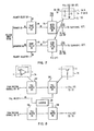
- a ramp select circuit 50 which includes an attenuator stage similar to attenuator stage 10 (Fig. 1), and a high pass filter 52, which acts as a limited bandwidth differentiator and includes a charging capacitor C, and resistor R f .
- a buffer stage 44 which includes an attenuator stage similar to the attenuator stage 16 (Fig. 1), a low pass filter 46 and an inverter 48.
- Each of the low pass filters 36, 40 and 46 provides 6 db/octave or a total 18 db/octave rolloff, without adding any delays in the operation of the circuit components.
- the multiple slope rolloff suppresses the high noise level which tends to be present in a broad bandwidth system.
- Additional summing and low pass filter elements similar to 38 and 40 may be added following filter 40 to increase the rolloff beyond 18db/octave for high resonance systems without adding delay or affecting accuracy.
- the buffered current signal must be input to each additional summer similar to summing circuit 38 interconnection.
- the single section high pass filter 52 serves as a low bandwidth differentiator which operates over a limited range, thereby minimizing high frequency noise in the processed signal.
- the high pass filter may operate over a range of 400 Hertz in a system which employs a 20 kiloHertz bandwidth.
- the upper stage 44 of the current channel receives the current signal from the voice coil motor and provides a buffered current signal to the summing circuit 38.
- the buffer output is also passed through the low pass filter 46 to provide a current reference signal to the resistor R2 of the summing circuit 34 and to track and fill circuit 32.
- the buffer output is also directed to the inverter 48 to provide an inverted current signal to the resistor R1 of the summing circuit 34.
- the ramp select circuit 50 of the position channel receives the position error signal 6A and a polarity select signal 6C from the level detector 42.
- the circuit senses the slope polarity of the position error signal and generates a succession of positive going slopes.
- the ramp select circuit selects as its output the slope of the position error signal between the limits of its linear region which may be positive going or negative going to produce a succession of positive slopes.
- Each ramp represents the traversal of a servo track, and the zero crossings of the position error signal indicate that the track centre has been traversed.
- the ramp select circuit thus generates a position ramp signal 6B that is a function of the position error signal.
- the position ramp signal 6B is directed through the high pass filter 52 which receives the fill signal output from the track and fill circuit 32.
- the differentiated position signal from the filter 52 is then fed to the summing circuit 34.
- the position error signal has nonlinear regions (Fig. 6) which occur in the area of the signal discontinuity produced when the servo head is between servo tracks.
- the track and fill circuit 32 operates to fill in the nonlinear regions so that the position velocity signal and fill signal form a continuous velocity signal. This is accomplished by clamping the output of the high pass filter 52 to the velocity signal level produced by track and fill circuit 32 during the nonlinear regions of the position error signal.
- the track and fill circuit 32 (Fig. 5) includes a buffer network 54 consisting of buffer amplifier 56 and analog comparator 58.
- the respective outputs of the amplifier 56 and comparator 58 are connected to opposite poles of a double-pole switch 62 whose output is coupled to an integrator 60.
- the output of the integrator is fed back to the comparator 58 and coupled to a fill in switch 64, whose output is connected to the high pass filter of position channel 27.
- the comparator 58 compares the output signal from the position channel 27 with the signal obtained from the integrator 60 when the double pole switch 62 is closed in the track mode.
- the comparator 58 and integrator 60 are coupled in a closed feedback loop.
- an error signal is generated.
- the integrator 60 is activated and integrates the error signal until the input signals to the comparator 58 are equal and there is no error signal.
- the switch 62 remains closed in the track position during the linear region of the position error signal and the integrator output signal is identical to and tracks the position velocity signal in the linear signal region.
- the fill select signal 6D operates the switch 62 to the fill mode, and the integrator 60 is disconnected from the comparator 58 and connected to the current channel buffer amplifier 56.
- the fill select signal 6D also operates the fill in switch 64 to connect the integrator output fill signal to the position channel 27.
- the fill-in signal is derived by integrating the current reference signal with initial conditions on the integrator set by the position velocity signal during linear region operation (track mode).
- the fill-in signal serves to clamp the output of high pass filter 52 during recovery of the position ramp circuit 68 and during the peak portions of the position error signal 6A when nonlinearities occur. In this manner, the velocity signal is filled in an continuously updated by integration of the voice coil motor current during nonlinear position error signal regions, thus providing a continuous and accurate velocity signal from the position channel during linear and nonlinear position error signal regions.
- quadrature position error signals are used.
- This embodiment utilizes the basic elements of the tachometer circuit shown in Fig. 2 with modifications to the position channel 27 and to the track and fill circuit 32.
- the use of quadrature signals substantially reduces the deleterious effects of the position error signal nonlinearities on the position channel velocity signal.
- primary and quadrature channels are utilized in the position channel (Fig. 7).
- the primary position error signals 9A and quadrature position error signals 9B are applied respectively to ramp select circuits 66 and 68.
- Polarity select signals 9C and 9D respectively are also directed from a level detector (not shown) to the ramp select circuits 66 and 68.
- Position ramp signals 9E and 9F which are generated by the primary and quadrature ramp select circuits, are processed by high pass filter circuits 70 and 72 that operate to generate position velocity signals, as discussed above in relation to filter 52.
- Each high pass filter circuit acts as a limited bandwidth differentiator and includes a charging capacitor 73 and resistor 75.
- the output signals from both high pass filters are connected to the summing circuit 34, which has an additional resistor to accommodate the second channel input signal.
- the fill select signals 9G from the level detector are symmetrical and are used to provide controls to the track and fill circuit (Fig. 8).
- the velocity signal from the primary position channel high pass filter 70 is buffered by fill buffer 74P and appears at fill switch 78P.
- the quadrature position error signal 9B is nonlinear and fill-in is required to maintain velocity signal accuracy.
- Fill-in is provided by fill buffer 74P through fill switch 78P to clamp the output of high pass filter 72Q to the correct signal output level. This fill-in continues until quadrature position error signal 98 returns to the linear region and the output from high pass filter 72Q is unclamped.
- the primary position error signal 9A reaches the extreme of its linear region and fill-select signal 9G reverses polarity. This opens the fill switch 78P and through inverter 80 closes fill switch 78Q.
- the quadrature position velocity output signal from filter 72 is buffered by fill buffer 74Q and appears at fill switch 78Q which is now energized. This signal effectively clamps the primary position velocity signal output from filter 70 to the correct signal level during the nonlinear region of the primary position error signal.
- an electronic tachometer circuit which employs the position error signal and voice coil motor current to generate a velocity signal, which is made to be continuously accurate over a broad range of velocities by means of a novel circuit including a low-bandwidth differentiator that provides fill-in of discontinuous nonlinear regions of the position error signal with continuous update.
- a rolloff of -18db/octave is realized to reduce resonant feedback effects and to enhance servo system stability without limiting velocity signal bandwidth.
Landscapes
- Physics & Mathematics (AREA)
- General Physics & Mathematics (AREA)
- Control Of Linear Motors (AREA)
- Moving Of The Head To Find And Align With The Track (AREA)
- Control Of Position Or Direction (AREA)
- Adjustment Of The Magnetic Head Position Track Following On Tapes (AREA)
Applications Claiming Priority (2)
| Application Number | Priority Date | Filing Date | Title |
|---|---|---|---|
| US05/947,278 US4246536A (en) | 1978-09-29 | 1978-09-29 | Electronic velocity measurement device |
| US947278 | 1992-09-18 |
Publications (2)
| Publication Number | Publication Date |
|---|---|
| EP0009663A1 EP0009663A1 (en) | 1980-04-16 |
| EP0009663B1 true EP0009663B1 (en) | 1983-06-08 |
Family
ID=25485877
Family Applications (1)
| Application Number | Title | Priority Date | Filing Date |
|---|---|---|---|
| EP79103350A Expired EP0009663B1 (en) | 1978-09-29 | 1979-09-07 | Electronic tachometer circuit |
Country Status (4)
| Country | Link |
|---|---|
| US (1) | US4246536A (OSRAM) |
| EP (1) | EP0009663B1 (OSRAM) |
| JP (1) | JPS5548658A (OSRAM) |
| DE (1) | DE2965621D1 (OSRAM) |
Families Citing this family (13)
| Publication number | Priority date | Publication date | Assignee | Title |
|---|---|---|---|---|
| US4321517A (en) * | 1979-12-03 | 1982-03-23 | Storage Technology Corporation | Resonance suppression method |
| DE3203257A1 (de) * | 1982-02-01 | 1983-08-11 | Siemens AG, 1000 Berlin und 8000 München | Vorrichtung zum bestimmen der gemeinsamen frequenz zweier unabhaengig veraenderlicher wechselgroessen, insbesondere bei einer drehfeldmaschine |
| JPS60101617A (ja) * | 1983-11-07 | 1985-06-05 | Matsushita Electric Ind Co Ltd | デイジタルサ−ボ制御装置 |
| JPS60177433U (ja) * | 1984-05-04 | 1985-11-25 | 三菱電機株式会社 | 熱動素子 |
| JPH0750116B2 (ja) * | 1986-02-19 | 1995-05-31 | 株式会社日立製作所 | 回転情報出力装置 |
| US4679103A (en) * | 1986-04-29 | 1987-07-07 | International Business Machines Corporation | Digital servo control system for a data recording disk file |
| DE3641538A1 (de) * | 1986-12-05 | 1988-06-09 | Heidelberger Druckmasch Ag | Einrichtung zum erfassen der drehzahl eines buerstenlosen gleichstrommotors |
| US4967291A (en) * | 1988-11-02 | 1990-10-30 | Miniscribe Corporation | Method and apparatus for preventing an over-velocity error condition of a hard disk drive system |
| DE19524913A1 (de) * | 1995-07-08 | 1997-01-09 | Bosch Gmbh Robert | Verfahren und Schaltungsanordnung zum Ermitteln der Drehzahl eines Gleichstrommotors |
| US7177106B2 (en) * | 2001-02-26 | 2007-02-13 | Matsushita Electric Industrial Co., Ltd. | Disk storage apparatus |
| EP1316956A3 (en) * | 2001-11-28 | 2004-07-21 | Matsushita Electric Industrial Co., Ltd. | Disk storage apparatus and disk storage apparatus control method |
| US7187142B2 (en) * | 2005-05-25 | 2007-03-06 | Rockwell Automation Technologies, Inc. | Motor drive with velocity noise filter |
| US7109670B1 (en) * | 2005-05-25 | 2006-09-19 | Rockwell Automation Technologies, Inc. | Motor drive with velocity-second compensation |
Family Cites Families (14)
| Publication number | Priority date | Publication date | Assignee | Title |
|---|---|---|---|---|
| US3351829A (en) * | 1964-01-30 | 1967-11-07 | Bofors Ab | Stabilizing device for a control system |
| US3568059A (en) * | 1969-01-21 | 1971-03-02 | Information Storage Systems | Electronic tachometer |
| US3839665A (en) * | 1970-03-30 | 1974-10-01 | A Gabor | Apparatus measuring relative velocity of movable members including means to detect velocity from the position encoder |
| US3811091A (en) * | 1972-08-24 | 1974-05-14 | Itel Corp | Electronic tachometer |
| GB1396834A (en) * | 1973-01-31 | 1975-06-04 | Ibm | Data storage apparatus |
| US3820712A (en) * | 1973-03-12 | 1974-06-28 | Ibm | Electronic tachometer |
| US3883894A (en) * | 1973-10-19 | 1975-05-13 | Storage Disk Corp | Disk drive servo system |
| US3942114A (en) * | 1974-10-15 | 1976-03-02 | Keeling William E | Speed detector and indicator for DC motors |
| US4030132A (en) * | 1975-03-27 | 1977-06-14 | Memorex Corporation | Dual mode velocity servo control for a linear actuator motor |
| GB1499268A (en) * | 1976-06-30 | 1978-01-25 | Ibm | Servo apparatus |
| GB1520350A (en) * | 1976-12-22 | 1978-08-09 | Ibm | Data storage apparatus |
| US4138728A (en) * | 1977-06-29 | 1979-02-06 | International Business Machines Corporation | Electronic tachometer with variable bandwidth differentiator |
| US4133011A (en) * | 1977-12-23 | 1979-01-02 | International Business Machines Corporation | Sampled data positioning system employing a model of the physical system for time optimal control |
| US4168457A (en) * | 1977-12-29 | 1979-09-18 | Sperry Rand Corporation | Self adaptive speed control system |
-
1978
- 1978-09-29 US US05/947,278 patent/US4246536A/en not_active Expired - Lifetime
-
1979
- 1979-08-14 JP JP10284879A patent/JPS5548658A/ja active Granted
- 1979-09-07 DE DE7979103350T patent/DE2965621D1/de not_active Expired
- 1979-09-07 EP EP79103350A patent/EP0009663B1/en not_active Expired
Also Published As
| Publication number | Publication date |
|---|---|
| EP0009663A1 (en) | 1980-04-16 |
| JPS6315555B2 (OSRAM) | 1988-04-05 |
| JPS5548658A (en) | 1980-04-07 |
| DE2965621D1 (en) | 1983-07-14 |
| US4246536A (en) | 1981-01-20 |
Similar Documents
| Publication | Publication Date | Title |
|---|---|---|
| EP0009663B1 (en) | Electronic tachometer circuit | |
| US5585976A (en) | Digital sector servo incorporating repeatable run out tracking | |
| US4184108A (en) | Self-regulating electronic tachometer | |
| US5199017A (en) | Optical disk drive and method for counting the number of tracks on an optical disk | |
| JPS60136040A (ja) | デ−タ記録装置用サ−ボ制御装置 | |
| US5339299A (en) | Optical disk drive apparatus for searching a target track | |
| US6249497B1 (en) | Seek control method in optical storage device | |
| EP0139531B1 (en) | Track following servo for higher density disk files | |
| JPH0738136B2 (ja) | 位置決め制御装置 | |
| EP0453223A2 (en) | Automatic loop gain control apparatus | |
| US5396479A (en) | Apparatus and method for setting a threshold level to maintain duty cycle in a pulse width modulated optical recording system | |
| US4885516A (en) | Techniques for disk servo track following | |
| US4577244A (en) | Techniques for disk servo | |
| USRE36864E (en) | Optical disk drive and methods for counting the number of tracks on an optical disk | |
| EP0479473B1 (en) | Apparatus for and method of counting the number of tracks on an optical disk | |
| JPH0237578A (ja) | 光学式記録および/または再生装置におけるアクセス速度検出装置 | |
| JPS62293577A (ja) | 磁気ヘツドの位置決め制御装置 | |
| JPS6034144Y2 (ja) | 磁気ヘツド位置決め装置 | |
| JP2617951B2 (ja) | 光学ピックアップの速度検出装置 | |
| JPH02304782A (ja) | 磁気デイスク装置の制御方法 | |
| JPH0755718Y2 (ja) | 光ディスクのシーク装置 | |
| JPH04245079A (ja) | ヘッドの位置決め制御方式 | |
| JPS644270B2 (OSRAM) | ||
| JPH0414607A (ja) | 磁気記録再生装置 | |
| JPS60182073A (ja) | デ−タ記憶装置 |
Legal Events
| Date | Code | Title | Description |
|---|---|---|---|
| PUAI | Public reference made under article 153(3) epc to a published international application that has entered the european phase |
Free format text: ORIGINAL CODE: 0009012 |
|
| AK | Designated contracting states |
Designated state(s): DE FR GB |
|
| 17P | Request for examination filed | ||
| GRAA | (expected) grant |
Free format text: ORIGINAL CODE: 0009210 |
|
| AK | Designated contracting states |
Designated state(s): DE FR GB |
|
| REF | Corresponds to: |
Ref document number: 2965621 Country of ref document: DE Date of ref document: 19830714 |
|
| ET | Fr: translation filed | ||
| PLBE | No opposition filed within time limit |
Free format text: ORIGINAL CODE: 0009261 |
|
| STAA | Information on the status of an ep patent application or granted ep patent |
Free format text: STATUS: NO OPPOSITION FILED WITHIN TIME LIMIT |
|
| 26N | No opposition filed | ||
| PGFP | Annual fee paid to national office [announced via postgrant information from national office to epo] |
Ref country code: FR Payment date: 19890825 Year of fee payment: 11 |
|
| PGFP | Annual fee paid to national office [announced via postgrant information from national office to epo] |
Ref country code: DE Payment date: 19891012 Year of fee payment: 11 |
|
| PGFP | Annual fee paid to national office [announced via postgrant information from national office to epo] |
Ref country code: GB Payment date: 19900803 Year of fee payment: 12 |
|
| PG25 | Lapsed in a contracting state [announced via postgrant information from national office to epo] |
Ref country code: FR Effective date: 19910530 |
|
| PG25 | Lapsed in a contracting state [announced via postgrant information from national office to epo] |
Ref country code: DE Effective date: 19910601 |
|
| REG | Reference to a national code |
Ref country code: FR Ref legal event code: ST |
|
| PG25 | Lapsed in a contracting state [announced via postgrant information from national office to epo] |
Ref country code: GB Effective date: 19910907 |
|
| GBPC | Gb: european patent ceased through non-payment of renewal fee |