EP0008481B1 - Device for hot-stretching thermoplastic parisons during blow-moulding - Google Patents
Device for hot-stretching thermoplastic parisons during blow-moulding Download PDFInfo
- Publication number
- EP0008481B1 EP0008481B1 EP79200450A EP79200450A EP0008481B1 EP 0008481 B1 EP0008481 B1 EP 0008481B1 EP 79200450 A EP79200450 A EP 79200450A EP 79200450 A EP79200450 A EP 79200450A EP 0008481 B1 EP0008481 B1 EP 0008481B1
- Authority
- EP
- European Patent Office
- Prior art keywords
- rod
- preforms
- wedges
- slots
- sleeve
- Prior art date
- Legal status (The legal status is an assumption and is not a legal conclusion. Google has not performed a legal analysis and makes no representation as to the accuracy of the status listed.)
- Expired
Links
- 238000000071 blow moulding Methods 0.000 title claims abstract description 14
- 229920001169 thermoplastic Polymers 0.000 title claims abstract description 4
- 239000004416 thermosoftening plastic Substances 0.000 title claims abstract description 4
- 238000006073 displacement reaction Methods 0.000 claims description 5
- 238000006243 chemical reaction Methods 0.000 claims description 2
- 230000005540 biological transmission Effects 0.000 claims 1
- 238000007664 blowing Methods 0.000 description 31
- 238000000465 moulding Methods 0.000 description 21
- 239000012530 fluid Substances 0.000 description 5
- 238000013459 approach Methods 0.000 description 4
- 238000004519 manufacturing process Methods 0.000 description 3
- 230000002159 abnormal effect Effects 0.000 description 2
- 230000001143 conditioned effect Effects 0.000 description 2
- 238000000034 method Methods 0.000 description 2
- 239000012815 thermoplastic material Substances 0.000 description 2
- 230000009286 beneficial effect Effects 0.000 description 1
- 230000000295 complement effect Effects 0.000 description 1
- 230000003750 conditioning effect Effects 0.000 description 1
- 239000000470 constituent Substances 0.000 description 1
- 230000000694 effects Effects 0.000 description 1
- 230000001939 inductive effect Effects 0.000 description 1
- 238000001746 injection moulding Methods 0.000 description 1
- 230000014759 maintenance of location Effects 0.000 description 1
- 239000000463 material Substances 0.000 description 1
- 230000000750 progressive effect Effects 0.000 description 1
- 238000005057 refrigeration Methods 0.000 description 1
- 238000007789 sealing Methods 0.000 description 1
Images


Classifications
-
- B—PERFORMING OPERATIONS; TRANSPORTING
- B29—WORKING OF PLASTICS; WORKING OF SUBSTANCES IN A PLASTIC STATE IN GENERAL
- B29C—SHAPING OR JOINING OF PLASTICS; SHAPING OF MATERIAL IN A PLASTIC STATE, NOT OTHERWISE PROVIDED FOR; AFTER-TREATMENT OF THE SHAPED PRODUCTS, e.g. REPAIRING
- B29C49/00—Blow-moulding, i.e. blowing a preform or parison to a desired shape within a mould; Apparatus therefor
- B29C49/42—Component parts, details or accessories; Auxiliary operations
- B29C49/58—Blowing means
-
- B—PERFORMING OPERATIONS; TRANSPORTING
- B29—WORKING OF PLASTICS; WORKING OF SUBSTANCES IN A PLASTIC STATE IN GENERAL
- B29C—SHAPING OR JOINING OF PLASTICS; SHAPING OF MATERIAL IN A PLASTIC STATE, NOT OTHERWISE PROVIDED FOR; AFTER-TREATMENT OF THE SHAPED PRODUCTS, e.g. REPAIRING
- B29C49/00—Blow-moulding, i.e. blowing a preform or parison to a desired shape within a mould; Apparatus therefor
- B29C49/08—Biaxial stretching during blow-moulding
- B29C49/10—Biaxial stretching during blow-moulding using mechanical means for prestretching
- B29C49/12—Stretching rods
-
- B—PERFORMING OPERATIONS; TRANSPORTING
- B29—WORKING OF PLASTICS; WORKING OF SUBSTANCES IN A PLASTIC STATE IN GENERAL
- B29C—SHAPING OR JOINING OF PLASTICS; SHAPING OF MATERIAL IN A PLASTIC STATE, NOT OTHERWISE PROVIDED FOR; AFTER-TREATMENT OF THE SHAPED PRODUCTS, e.g. REPAIRING
- B29C2949/00—Indexing scheme relating to blow-moulding
- B29C2949/07—Preforms or parisons characterised by their configuration
- B29C2949/0715—Preforms or parisons characterised by their configuration the preform having one end closed
-
- B—PERFORMING OPERATIONS; TRANSPORTING
- B29—WORKING OF PLASTICS; WORKING OF SUBSTANCES IN A PLASTIC STATE IN GENERAL
- B29C—SHAPING OR JOINING OF PLASTICS; SHAPING OF MATERIAL IN A PLASTIC STATE, NOT OTHERWISE PROVIDED FOR; AFTER-TREATMENT OF THE SHAPED PRODUCTS, e.g. REPAIRING
- B29C49/00—Blow-moulding, i.e. blowing a preform or parison to a desired shape within a mould; Apparatus therefor
- B29C49/02—Combined blow-moulding and manufacture of the preform or the parison
- B29C49/06—Injection blow-moulding
-
- B—PERFORMING OPERATIONS; TRANSPORTING
- B29—WORKING OF PLASTICS; WORKING OF SUBSTANCES IN A PLASTIC STATE IN GENERAL
- B29C—SHAPING OR JOINING OF PLASTICS; SHAPING OF MATERIAL IN A PLASTIC STATE, NOT OTHERWISE PROVIDED FOR; AFTER-TREATMENT OF THE SHAPED PRODUCTS, e.g. REPAIRING
- B29C49/00—Blow-moulding, i.e. blowing a preform or parison to a desired shape within a mould; Apparatus therefor
- B29C49/08—Biaxial stretching during blow-moulding
- B29C49/10—Biaxial stretching during blow-moulding using mechanical means for prestretching
- B29C49/12—Stretching rods
- B29C49/1202—Means for fixing the stretching rod to the driving means, e.g. clamping means or bayonet connections
-
- B—PERFORMING OPERATIONS; TRANSPORTING
- B29—WORKING OF PLASTICS; WORKING OF SUBSTANCES IN A PLASTIC STATE IN GENERAL
- B29C—SHAPING OR JOINING OF PLASTICS; SHAPING OF MATERIAL IN A PLASTIC STATE, NOT OTHERWISE PROVIDED FOR; AFTER-TREATMENT OF THE SHAPED PRODUCTS, e.g. REPAIRING
- B29C49/00—Blow-moulding, i.e. blowing a preform or parison to a desired shape within a mould; Apparatus therefor
- B29C49/08—Biaxial stretching during blow-moulding
- B29C49/10—Biaxial stretching during blow-moulding using mechanical means for prestretching
- B29C49/122—Drive means therefor
- B29C49/1229—Drive means therefor being a cam mechanism
Definitions
- the present invention relates to a device for the longitudinal hot stretching of preforms of thermoplastic material having a closed bottom and an open neck during their blow molding for the production of hollow bodies.
- thermoplastic hollow bodies are widely used for the production of thermoplastic hollow bodies.
- preforms having a closed bottom and an open neck are produced, then, in a second stage, these preforms are blown in order to produce the desired hollow bodies.
- the preforms are produced by injection molding or by blow molding and have a diameter and a height which are clearly less than the diameter and the height of the hollow bodies to be produced.
- the longitudinal stretching of the preforms is carried out by means of stretching rods which are introduced into the preforms by their open neck and which exert a thrust force on their closed bottom.
- the stroke of the drawing rods is generally calculated so as to stretch the preforms held by their neck longitudinally until they reach a length which is practically equal to or slightly less than the height of the desired hollow bodies. Since the hydraulic or pneumatic drive systems are incapable of ensuring displacement of the drawing rods with sufficient regularity, these are generally actuated mechanically, for example by the intervention of cams. Devices of this type are described in documents FR-A-2304461 and FR-A-2098332.
- a device for blowing oriented hollow bodies in which blowing nozzles are used fitted with an annular groove in which retention balls can be inserted by thrust springs.
- the function of this mechanism is to promote the centering in height of the blowing nozzle in the mold and to allow rapid decoupling of the nozzle when it is removed from the mold.
- a blowing nozzle with a telescopic end piece is recalled by a spring, this assembly having the sole purpose of limiting the displacement of the end piece and thus preventing the latter from being able to apply the walls of the blank against the wall of the mold cavity.
- the object of the present invention is to remedy this drawback of known devices.
- the invention as characterized in the claims, aims in fact to create a device for the longitudinal hot drawing of preforms of thermoplastic material during their blow molding, these preforms having a closed bottom and an open neck and this device comprising a mechanically actuated longitudinal stretching rod which is released when the thrust exerted on the bottom of the preforms exceeds a predetermined value so as to surely prevent the perforation of the bottom of the preforms during their stretching.
- the device, object of the invention comprises a longitudinal stretching rod, arranged so as to exert an axial thrust on the bottom of the preforms and mechanically actuated which is provided with notches and is actuated by a drive sleeve in which it can slide and with which it is secured by means of retractable shims which are received in the notches.
- the shims can be moved in a direction perpendicular to the axis of the drawing rod.
- the notches formed on the drawing rod and the retractable shims are profiled so that the reaction to the thrust force transmitted by the retractable shims tends to extract them out notches, the retractable shims being held in place by calibrated springs.
- the notches formed on the drawing rod comprise an oblique surface with respect to the axis of the drawing rod on which come to rest retractable shims constituted by rollers which are held in place by calibrated pushers and springs.
- the molding unit illustrated is part of a blow molding apparatus comprising a series of such units, mounted radially on a support, not shown, which is preferably rotatable.
- Each molding unit comprises a blowing mold 1, a blowing device 2, a longitudinal drawing rod 3, a drive sleeve 4 for the drawing rod, and a stop 5.
- the blowing mold 1 is of the conventional type and generally consists of two complementary half-molds.
- the blowing device 2 is also of the conventional type, apart from the fact that the drawing rod 3, which is coaxial with it, can slide freely through it.
- the blowing device comprises a blowing nozzle 6, a conduit 7 for supplying the expansion fluid, a housing 8 for distributing the expansion fluid, a spring device 9 tightly applying the blowing nozzle 6 against the mouth of the blow mold 1 during the blow molding of the preforms, and a sealing device 10 preventing the loss of expansion fluid between the distribution box 8 and the drawing rod 3t
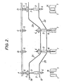
- the blowing device is controlled by a profiled cam 17 (FIGS. 2 and 3) which brings this device into close contact with the mouth of the mold 1 when the latter is closed and contains a preform 19 to be blow molded and which discards this device of the mouth of the mold 1 after the blow molding operation.
- a profiled cam 17 FIGS. 2 and 3
- the end of the drawing rod 3 which exerts the pushing force on the bottom of the preforms is profiled so as to minimize any risk of damage to the bottom of the preforms; this end is therefore devoid of sharp angles.
- the driving sleeve 4 (FIG. 1) of the drawing rod 3 encloses the drawing rod 3 proper as well as a control sleeve 11 wedged on the leading end of the drawing rod 3, c ' is this control sleeve which has notches 12 whose profile has the shape of a flattened M.
- the control sleeve 11 which is completely integral with the drawing rod 3 can slide in the cylindrical part 13 of the drive sleeve 4.
- the latter is fitted with calibrated springs 14 and pushers 15 acting on rollers 16 applied by these springs 14 against the hollow of the notches 12 of the control sleeve 11.
- the drive sleeve 4 is actuated by a profiled control cam 18 ( Figures 2 and 3) which governs its movements.
- the stop 5 is constituted by a hollow tube in which the leading end of the drawing rod 3 can be inserted and against the end of which the control sleeve 11 can come into abutment wedged on this drawing rod 3.
- the control cam 18 of the drive sleeve 4 can be shaped in such a way that the longitudinal stretching of the preforms is carried out before or during the final blow molding.
- the control cam 18 of the drive sleeve 4 can, moreover, be designed so as to return this sleeve to its initial position after the stretching and final blowing operations so that the stretching rod 3 is brought back in the starting position for a new cycle.
- the stop 5 can be used to block the leading end of the drawing rod 3 during its ascent. Furthermore, it correctly reintroduces the control sleeve 11 of the drawing rod 3 into the drive sleeve 4 in the case where the latter has come out of the latter due to an accidental overshooting of the predetermined limit value of the thrust force exerted by the drawing rod 3.
- the blowing device 2 gradually approaches the closed mold 1 and the nozzle 6 is applied to the mouth of the mold 1 when the molding unit reaches the end of the inclined parts 20 and 21 of the profiling of the cams 17 and 18.
- the drive sleeve 4 approaches the blowing device 2, which causes the sliding of the drawing rod 3 to through the blowing device 2 and therefore the longitudinal stretching of the preform 19 enclosed in the mold 1.
- the profiling of the section 21 of the cam 18 is designed in such a way that, when the molding unit reaches position B, the desired longitudinal stretch for the preforms 19 is reached.
- the molding unit approaches the inclined parts 22 and 23 of the cams 17 and 18.
- the profiling 23 causes the progressive withdrawal of the drawing rod 3 and the profiling 22 causes the withdrawal of the blowing device 2 with respect to to the mold 1.
- the control sleeve 11 of the drawing rod abuts against the stop 5 and the blowing device 2 as well as the drive sleeve 4 of the drawing rod 3 have returned to their initial position as shown in position D.
- the mold 1 is gradually opened and the molded hollow body 24 is removed from the mold.
- the rollers 16 of the pushers 15 are pushed against the action of the springs 14 and the drive sleeve 4 no longer drives the longitudinal drawing rod 3 via the control sleeve 11.
- the drive sleeve 4 causes, via the control sleeve 11, the descent of the longitudinal stretching rod 3 in the preform 19 until the pushing force exerted by this stretching rod 3 reaches the predetermined value and, at this time , the drive sleeve ceases to drive the drawing rod 3 due to a relative movement between the drive sleeve 13 and the control sleeve 11.
- control sleeve 11 is extracted, in this case, from the cylindrical part 13 of the drive sleeve 4 and the preform is no longer axially stretched.
- control sleeve 11 abuts against the stop 5 during the ascent of the drive unit 13 under the effect of the profiling 23 of the cam 18. This stop retains the drawing rod 3 and forces the control sleeve 11 into the drive sleeve 4 so that all the elements of the device have returned to their initial position when the molding unit is in position D and a new molding cycle can be undertaken.
- the molding units are, for the sake of clarity, represented as if they were moving in a plane, but it is quite obvious that in the case of a rotary apparatus, the molding units can follow a circular path.
- the device according to the invention is particularly suitable for the production of molecularly bioriented hollow bodies: it suffices to use preforms thermally conditioned at a temperature inducing, during drawing, molecular orientation tensions in their constituent material. .
- the preforms used in this case, which can advantageously be provided with a closed hemispherical bottom as described in Belgian patent 826 676 filed on 14.3. 1975 by the Applicant.
- the end of the drawing rod coming into contact with the bottom of the preforms is advantageously of hemispherical shape.
Landscapes
- Engineering & Computer Science (AREA)
- Manufacturing & Machinery (AREA)
- Mechanical Engineering (AREA)
- Blow-Moulding Or Thermoforming Of Plastics Or The Like (AREA)
- Processing And Handling Of Plastics And Other Materials For Molding In General (AREA)
Abstract
Description
La présente invention concerne un dispositif pour l'étirage à chaud longitudinal de préformes en matière thermoplastique présentant un fond fermé et un col ouvert lors de leur moulage par soufflage en vue de la production de corps creux.The present invention relates to a device for the longitudinal hot stretching of preforms of thermoplastic material having a closed bottom and an open neck during their blow molding for the production of hollow bodies.
Actuellement, les techniques de moulage par soufflage sont très largement exploitées pour la production de corps creux en matière thermoplastique.Currently, blow molding techniques are widely used for the production of thermoplastic hollow bodies.
Selon une des techniques les plus courantes, on réalise, dans une premier stade, des préformes ayant un fond fermé et un col ouvert, puis, dans un second stade, on moule ces préformes par soufflage en vue de produire les corps creux désirés. En général, les préformes sont produites par moulage par injection ou par soufflage et ont un diamètre et une hauteur qui sont nettement Inférieures au diamètre et à la hauteur des corps creux à produire. Par ailleurs, il est avantageux de soumettre ces préformes à un étirage axial, avant ou durant l'étirage final de moulage par soufflage. Un tel étirage se révèle particulièrement bénéfique lorsque les préformes ont subi un conditionnement thermique préalable approprié à produire, lors du moulage final, des corps creux orientés moléculairement. Dans ce cas, en effet, l'étirage longitudinal des préformes engendre une orientation moléculaire axiale dans ces dernières tandis que l'étirage provoqué par le soufflage final engendre une orientation moléculaire radiale. On obtient ainsi des corps creux dont les parois sont biorientées moléculairement selon des directions orthogonales et qui se caractérisent par des propriétés mécaniques exceptionnelles.According to one of the most common techniques, in a first stage, preforms having a closed bottom and an open neck are produced, then, in a second stage, these preforms are blown in order to produce the desired hollow bodies. In general, the preforms are produced by injection molding or by blow molding and have a diameter and a height which are clearly less than the diameter and the height of the hollow bodies to be produced. Furthermore, it is advantageous to subject these preforms to axial stretching, before or during the final stretch of blow molding. Such stretching proves to be particularly beneficial when the preforms have undergone prior thermal conditioning suitable for producing, during the final molding, molecularly oriented hollow bodies. In this case, in fact, the longitudinal stretching of the preforms generates an axial molecular orientation in the latter while the stretching caused by the final blowing generates a radial molecular orientation. Hollow bodies are thus obtained, the walls of which are molecularly bioriented in orthogonal directions and which are characterized by exceptional mechanical properties.
En général, l'étirage longitudinal des préformes est réalisé au moyen de tiges d'étirage qui sont introduites dans les préformes par leur col ouvert et qui exercent un effort de poussée sur leur fond fermé. La course des tiges d'étirage est calculée en général de façon à étirer longitudinalement les préformes maintenues par leur col jusqu'au moment où celles-ci atteignent une longueur qui est pratiquement égale ou légèrement inférieure à la hauteur des corps creux désirés. Etant donné que les systèmes d'entraînement hydrauliques ou pneumatiques sont incapables d'assurer de déplacement des tiges d'étirage avec une régularité suffisante, celles-ci sont en général actionnées mécaniquement, par exemple à l'intervention de cames. Des dispositifs de ce type sont décrits dans les documents FR-A-2304461 et FR-A-2098332.In general, the longitudinal stretching of the preforms is carried out by means of stretching rods which are introduced into the preforms by their open neck and which exert a thrust force on their closed bottom. The stroke of the drawing rods is generally calculated so as to stretch the preforms held by their neck longitudinally until they reach a length which is practically equal to or slightly less than the height of the desired hollow bodies. Since the hydraulic or pneumatic drive systems are incapable of ensuring displacement of the drawing rods with sufficient regularity, these are generally actuated mechanically, for example by the intervention of cams. Devices of this type are described in documents FR-A-2304461 and FR-A-2098332.
Par ailleurs, dans le document DE-A-2704657, on décrit un dispositif de soufflage de corps creux orientés dans lequel il est fait appel à des tuyères de soufflage équipées d'une gorge annulaire dans laquelle des billes de rétention peuvent être insérées par des ressorts de poussée. Ce mécanisme a pour fonction de favoriser le centrage en hauteur de la tuyère de soufflage dans le moule et de permettre un découplage rapide de la tuyère lors de son retrait du moule. Dans le document FR-A-2323516, on décrit une tuyère de soufflage à embout téléscopique rappelé par un ressort, ce montage ayant pour seul but de limiter le déplacement de l'embout et d'empêcher ainsi que celui-ci ne puisse appliquer les parois de l'ébauche contre la paroi de la cavité du moule.Furthermore, in document DE-A-2704657, a device for blowing oriented hollow bodies is described, in which blowing nozzles are used fitted with an annular groove in which retention balls can be inserted by thrust springs. The function of this mechanism is to promote the centering in height of the blowing nozzle in the mold and to allow rapid decoupling of the nozzle when it is removed from the mold. In document FR-A-2323516, a blowing nozzle with a telescopic end piece is recalled by a spring, this assembly having the sole purpose of limiting the displacement of the end piece and thus preventing the latter from being able to apply the walls of the blank against the wall of the mold cavity.
L'emploi de tiges d'étirage actionnées mécaniquement présente un inconvénient très sérieux. En effet, il arrive fréquemment que, lors de leur déplacement obligé, les tiges d'étirage exercent un effort de poussée trop élevé sur les fonds des préformes et les perforent. Un tel incident peut se produire, par exemple, lorsque pour une raison quelconque, une préforme se trouve à une température inférieure, même légèrement, à la température prévue pour l'étirage. Dans un tel cas, la préforme n'est pas soufflée lors de l'introduction du fluide d'expansion et elle reste habituellement accrochée dans le moule ou à la tuyère de soufflage lors de l'ouverture du moule. Il faut dès lors prévoir la présence continuelle d'un opérateur pour éliminer manuellement les préformes perforées afin de libérer les moules de soufflage.The use of mechanically actuated drawing rods has a very serious drawback. Indeed, it frequently happens that, during their forced displacement, the drawing rods exert a too high thrust force on the bottoms of the preforms and perforate them. Such an incident can occur, for example, when for any reason a preform is at a temperature lower, even slightly, than the temperature intended for drawing. In such a case, the preform is not blown during the introduction of the expansion fluid and it usually remains attached to the mold or to the blowing nozzle when the mold is opened. It is therefore necessary to provide for the continual presence of an operator to manually remove the perforated preforms in order to free the blow molds.
La présente invention a pour but de remédier à cet inconvénient des dispositifs connus. L'invention, telle qu'elle est caractérisée dans les revendications, vise en effet à créer un dispositif pour l'étirage à chaud longitudinal de préformes en matière thermoplastique lors de leur moulage par soufflage, ces préformes présentant un fond fermé et un col ouvert et ce dispositif comprenant une tige d'étirage longitudinal actionnée mécaniquement qui se dérobe lorsque la poussée exercée sur le fond des préformes dépasse une valeur prédéterminée de manière à empêcher de façon sûre la perforation du fond des préformes lors de leur étirage.The object of the present invention is to remedy this drawback of known devices. The invention, as characterized in the claims, aims in fact to create a device for the longitudinal hot drawing of preforms of thermoplastic material during their blow molding, these preforms having a closed bottom and an open neck and this device comprising a mechanically actuated longitudinal stretching rod which is released when the thrust exerted on the bottom of the preforms exceeds a predetermined value so as to surely prevent the perforation of the bottom of the preforms during their stretching.
Le dispositif, objet de l'invention, comprend une tige d'étirage longitudinal, disposée de façon à exercer une poussée axiale sur le fond des préformes et actionnée mécaniquement qui est pourvue d'encoches et est actionnée par un manchon d'entraînement dans lequel elle peut coulisser et avec lequel elle est solidarisée au moyen de cales rétractables venant se loger dans les encoches.The device, object of the invention, comprises a longitudinal stretching rod, arranged so as to exert an axial thrust on the bottom of the preforms and mechanically actuated which is provided with notches and is actuated by a drive sleeve in which it can slide and with which it is secured by means of retractable shims which are received in the notches.
Selon un mode re réalisation préféré du dispositif conforme à l'invention, les cales sont déplaçables suivant une direction perpendiculaire à l'axe de la tige d'étirage. Les encoches ménagées sur la tige d'étirage et les cales rétractables sont profilées de manière que la réaction à l'effort de poussée transmis par les cales rétractables tende à extraire celles-ci hors des encoches, les cales rétractables étant maintenues en place au moyen de ressorts tarés.According to a preferred embodiment of the device according to the invention, the shims can be moved in a direction perpendicular to the axis of the drawing rod. The notches formed on the drawing rod and the retractable shims are profiled so that the reaction to the thrust force transmitted by the retractable shims tends to extract them out notches, the retractable shims being held in place by calibrated springs.
Selon une variante préférée de ce mode de réalisation, les encoches ménagées sur la tige d'étirage comprennent une surface oblique par rapport à l'axe de la tige d'étirage sur laquelle viennent s'appuyer des cales rétractables constituées par des galets qui sont maintenus en place par des poussoirs et des ressorts tarés.According to a preferred variant of this embodiment, the notches formed on the drawing rod comprise an oblique surface with respect to the axis of the drawing rod on which come to rest retractable shims constituted by rollers which are held in place by calibrated pushers and springs.
Le dispositif conforme à l'invention est, par ailleurs, explicité plus en détail à l'aide de dessins dans la description qui va suivre d'un mode de réalisation préféré qui est donnée à titre illustratif.
- La figure 1 est une vue en coupe et en élévation d'une unité de moulage comportant un dispositif conforme à l'invention.
- La figure 2 est une vue schématique montrant un cycle de moulage normal.
- La figure 3 est une vue schématique montrant un cycle de moulage lorsque la poussée exercée par la tige d'étirage dépasse une valeur limite prédéterminée.
- Figure 1 is a sectional and elevational view of a molding unit comprising a device according to the invention.
- Figure 2 is a schematic view showing a normal molding cycle.
- Figure 3 is a schematic view showing a molding cycle when the thrust exerted by the drawing rod exceeds a predetermined limit value.
L'unité de moulage illustrée (figure 1) fait partie d'un appareillage de moulage par soufflage comportant une série de pareilles unités, montées radialement sur un support, non représenté, qui est de préférence rotatif. Chaque unité de moulage comporte un moule de soufflage 1, un dispositif de soufflage 2, une tige d'étirage longitudinal 3, un manchon d'entraînement 4 de la tige d'étirage, et un butée 5.The molding unit illustrated (Figure 1) is part of a blow molding apparatus comprising a series of such units, mounted radially on a support, not shown, which is preferably rotatable. Each molding unit comprises a blowing mold 1, a blowing
La moule de soufflage 1 est du type classique et est généralement constitué par deux demi- moules complémentaires.The blowing mold 1 is of the conventional type and generally consists of two complementary half-molds.
Le dispositif de soufflage 2 est également de type classique, mis à part le fait que la tige d'étirage 3, qui lui est coaxiale, peut coulisser librement au travers de celui-ci. Le dispositif de soufflage comporte une tuyère de soufflage 6, un conduit 7 d'amenée du fluide d'expansion, un boîter 8 de répartition du fluide d'expansion, un dispositif à ressort 9 appliquant étroitement la tuyère de soufflage 6 contre l'embouchure du moule de soufflage 1 lors du moulage par soufflage des préformes, et un dispositif d'étanchéité 10 empêchant les pertes de fluide d'expansiorr entre le boîtier de répartition 8 et la tige d'étirage 3tThe blowing
Le dispositif de soufflage est commandé par une came profilée 17 (figures 2 et 3) qui amène ce dispositif en contact étroit avec l'embouchure du moule 1 lorsque ce dernier est fermé et contient une préforme 19 à mouler par soufflage et qui écarte ce dispositif de l'embouchure du moule 1 après l'opération de moulage par soufflage.The blowing device is controlled by a profiled cam 17 (FIGS. 2 and 3) which brings this device into close contact with the mouth of the mold 1 when the latter is closed and contains a
L'extrémité de la tige d'étirage 3 qui exerce l'effort de poussée sur le fond des préformes est profilée de façon à minimiser tout risque d'endommagement du fond des préformes; cette extrémité est donc dépourvue d'angles vifs. Lorsque l'étirage longitudinal des préformes est effectué avant le soufflage final, il peut être avantageux de prévoir un léger présoufflage des préformes durant leur étirage de façon à éviter tout collage des préformes contre cette tige. II peut également être avantageux, lors du soufflage final, d'introduire le fluide d'expansion à une distance du fond des préformes comprise entre 20 et 60% de leur longueur soumise à l'expansion, cette introduction se faisant en direction du fond des préformes.The end of the
Le manchon d'entraînement 4 (figure 1 ) de la tige d'étirage 3 enserre la tige d'étirage 3 proprement dite ainsi qu'un manchon de commande 11 calé sur l'extrémité menante de la tige d'étirage 3, c'est ce manchon de commande qui comporte des encoches 12 dont le profil a la forme d'un M aplati. Le manchon de commande 11 qui est tout à fait solidaire de la tige d'étirage 3 peut coulisser dans la partie cylindrique 13 du manchon d'entraînement 4. Celui-ci est équipé de ressorts tarés 14 et de poussoirs 15 agissant sur des galets 16 appliqués par ces ressorts 14 contre le creux des encoches 12 du manchon de commande 11. Le manchon d'entraînement 4 est actionné par une came profilée de commande 18 (figures 2 et 3) qui régit ses déplacements.The driving sleeve 4 (FIG. 1) of the
La butée 5 est constituée par un tube creux dans lequel peut s'insérer l'extrémité menante de la tige d'étirage 3 et contre l'extrémité duquel peut venir buter le manchon de commande 11 calé sur cette tige d'étirage 3. La butée 5, qui peut être réglable accompagne l'unité. de moulage dans ses déplacements.The
Dans un tel dispositif, lorsque la came de commande 18 impose un déplacement au manchon d'entraînement 4, ce dernier entraîne la tige d'étirage 3' par l'intermédiaire des poussoirs 15 à galets 16 appliqués, par les ressorts 14, contre le creux des encoches 12 du manchon de commande 11 calé sur la tige 3. Lorsque, pour une raison quelconque, la poussée appliquée à la tige d'étirage dépasse une certaine valeur limite conditionnée à la fois par la puissance des ressorts tarés 14 et par l'angle de pente de la surface oblique des encoches du manchon de commande 11, les poussoirs 15 à galet 16 sont repoussés et la tige d'étirage 3 n'est plus entraînée.In such a device, when the
Il apparaît donc qu'en choisissant judicieusement les angles de la surface oblique des encoches 12 du manchon de commande 11 ainsi que la puissance des ressorts tarés 14 agissant sur les poussoirs 15 à galet 16, il est possible de régler avec précision l'effort maximum de poussée qui peut être transmis à la tige d'étirage 3. On peut, par ailleurs, prévoir des vis de réglage ou des moyens similaires pour régler la pression exercée par les ressorts tarés sur les poussoirs 15 à galet 16.It therefore appears that by judiciously choosing the angles of the oblique surface of the
La came de commande 18 du manchon d'entraînement 4 peut être profilée de façon telle que l'étirage longitudinal des préformes est effectué avant ou durant le moulage par soufflage final.The
II va de soi que durant la phase d'étirage longitudinal, la préforme 19 doit être maintenue par son col ouvert. Un moyen très simple pour obtenir ce résultat consiste à introduire la préforme 19 dans le moule de soufflage final 1 avant de procéder à son étirage longitudinal et de la maintenir par son col, durant cet étirage, per l'intermédiaire du moule 1 en collaboration éventuelle avec la tuyère de soufflage 6. Un autre moyen consisterait à maintenir la préforme par un moule de col approprié durant cet étirage, ce dernier pouvant être effectué dans ou à l'extérieur du moule de soufflage final.It goes without saying that during the stretching phase longitudinal, the
La came de commande 18 du manchon d'entraînement 4 peut, en outre, être conçue de façon à ramener ce manchon dans sa position initiale après les opérations d'étirage et de soufflage final de façon telle que la tige d'étirage 3 soit ramenée en position de départ pour un nouveau cycle. La butée 5 peut servir à bloquer l'extrémité menante de la tige d'étirage 3 lors de sa remontée. Par ailleurs, elle réintroduit correctement le manchon de commande 11 de la tige d'étirage 3 dans le manchon d'entraînement 4 dans le cas où ce dernier est sorti de celui-ci du fait d'un dépassement accidentel de la valeur limite prédéterminée de l'effort de poussée exercé par la tige d'étirage 3.The
Dans le cas d'un fonctionnement normal (figure 2), dans la position A (début d'un cycle d'étirage et de soufflage), le dispositif de soufflage 2 et le manchon d'entraînement 4 de la tige d'étirage 3 sont maintenus, par l'intermédiaire des cames profilées 17 et 18, en retrait du moule 1 qui se referme sur une préforme 19 à mouler, la fermeture du moule étant complète au moment où l'unité de moulage aborde les parties inclinées 20 et 21 du profilage des cames 17 et 18.In the case of normal operation (Figure 2), in position A (start of a stretching and blowing cycle), the blowing
Dès ce moment, le dispositif de soufflage 2 se rapproche progressivement du moule 1 fermé et la tuyère 6 est appliquée sur l'embouchure du moule 1 lorsque l'unité de moulage atteint la fin des parties inclinées 20 et 21 du profilage des cames 17 et 18. Simultanément, grâce à la came 18 dont le profilage 21 est plus accentué que celui de la came 17, le manchon d'entraînement 4 se rapproche du dispositif de soufflage 2, ce qui provoque le coulissement de la tige d'étirage 3 au travers du dispositif de soufflage 2 et partant l'étirage longitudinal de la préforme 19 enfermée dans le moule 1. Le profilage de la section 21 de la came 18 est conçu de façon telle que, lorsque l'unité de moulage atteint la position B, l'étirage longitudinal souhaité pour les préformes 19 est atteint.From this moment, the blowing
En position B, la tuyère de soufflage 6 est appliquée contre l'embouchure du moule 1 et la préforme 19 est étirée longitudinalement jusqu'à la longueur désirée.In position B, the blowing
Le moulage par soufflage de la préforme étirée est ensuite effectué tandis que l'unité de moulage progresse entre la position B et la position C, la tuyère de soufflage étant maintenue contre l'embouchure du moule 1. Il est naturellement possible de modifier le profilage des cames 17 et 18 de façon à réaliser simultanément l'étirage longitudinal et le soufflage de la préforme 19.The blow molding of the stretched preform is then carried out while the molding unit progresses between position B and position C, the blowing nozzle being held against the mouth of the mold 1. It is naturally possible to modify the
Lorsque l'unité de moulage atteint la position C, le soufflage de la préforme et la réfrigération du corps creux ainsi moulé sont terminés.When the molding unit reaches position C, the blowing of the preform and the refrigeration of the hollow body thus molded are completed.
A ce moment, l'unité de moulage aborde les parties inclinées 22 et 23 des cames 17 et 18. Le profilage 23 entraîne le retrait progressif de la tige d'étirage 3 et le profilage 22 entraîne le retrait du dispositif de soufflage 2 par rapport au moule 1. Lorsque l'unité de moulage atteint l'extrémité des profilages 22 et 23 des cames 17 et 18, le manchon de commande 11 de la tige d'étirage vient buter contre la butée 5 et le dispositif de soufflage 2 ainsi que le manchon d'entraînement 4 de la tige d'étirage 3 ont repris leur position initiale ainsi qu'il est montré à la position D.At this time, the molding unit approaches the
Par ailleurs, durant le passage de l'unité de moulage entre les positions C et D, le moule 1 est ouvert progressivement et le corps creux moulé 24 est évacué du moule.Furthermore, during the passage of the molding unit between positions C and D, the mold 1 is gradually opened and the molded
Dans le cas d'un fonctionnement anormal (figure 3), c'est-à-dire lorsque la poussée exercée par la tige d'étirage 3 sur le fond de la préforme 19 dépasse la valeur limite prédéterminée, le cycle de fonctionnement est analogue à celui qui vient d'être décrit mis à part les différences suivantes.In the case of abnormal operation (Figure 3), that is to say when the thrust exerted by the drawing
Lorsque l'unité de moulage passe de la position A à la position B et au moment où l'effort de poussée exercé par la tige d'étirage longitudinal 3 sur le fond de la préforme 19 atteint la valeur limite qui est prédéterminée, les galets 16 des poussoirs 15 sont repoussés contre l'action des ressorts 14 et le manchon d'entraînement 4 n'entraîne plus la tige d'étirage longitudinal 3 via le manchon de commande 11. En d'autres termes, le manchon d'entraînement 4 provoque, via le manchon de commande 11, la descente de la tige d'étirage longitudinal 3 dans la préforme 19 jusqu'au moment où l'effort de poussée exercé par cette tige d'étirage 3 atteint la valeur prédéterminée et, à ce moment, le manchon d'entraînement cesse d'entraîner la tige d'étirage 3 du fait d'un mouvement relatif entre le manchon d'entraînement 13 et le manchon de commande 11.When the molding unit changes from position A to position B and when the pushing force exerted by the
Ainsi qu'il apparaît dans la position B de la figure 3, le manchon de commande 11 s'extirpe, dans ce cas, de la partie cylindrique 13 du manchon d'entraînement 4 et la préforme n'est plus étirée axialement.As it appears in position B of FIG. 3, the
Toutefois, même dans ce cas de fonctionnement anormal lors de l'étirage, les moulage par soufflage se déroule normalement et la préforme est donc soufflée pour donner un corps creux qui se démoule normalement.However, even in this case of abnormal operation during stretching, the blow molding takes place normally and the preform is therefore blown to give a hollow body which unmolds normally.
Par ailleurs, lors du passage de l'unité de moulage entre les positions C et D, le manchon de commande 11 vient buter contre la butée 5 au cours de la remontée du boîter d'entraînement 13 sous l'effet du profilage 23 de la came 18. Cette butée retient la tige d'étirage 3 et force le manchon de commande 11 dans le manchon d'entraînement 4 de telle sorte que tous les éléments du dispositif ont repris leur position initiale lorsque l'unité de moulage se trouve en position D et un nouveau cycle de moulage peut être entrepris.Furthermore, during the passage of the molding unit between positions C and D, the
Dans les figures 2 et 3, les unités de moulage sont, par souci de clarté, représentées comme si celles-ci se déplaçaient dans un plan mais il est bien évident que dans le cas d'un appareillage rotatif, les unités de moulage peuvent suivre une trajectoire circulaire.In FIGS. 2 and 3, the molding units are, for the sake of clarity, represented as if they were moving in a plane, but it is quite obvious that in the case of a rotary apparatus, the molding units can follow a circular path.
Par ailleurs, il paraît bien évident que l'effort maximum de poussée qui peut être exercé par les tiges d'étirage longitudinal 3 peut être réglé avec une grande précision en agissant soit sur la puissance des ressorts tarés 14 scit sur le profilage des encoches 12 du manchon de commande 11.Furthermore, it seems very obvious that the maximum thrust force which can be exerted by the
Le dispositif conforme à l'invention convient particulièrement bien pour la production de corps creux biorientés moléculairement: il suffit de mettre en oeuvre des préformes conditionnées thermiquement à une température induisant, lors de l'étirage, des tensions d'orientation moléculaire dans leur matériau constitutif. Les préformes utilisées, dans ce cas, pouvant avantageusement être pourvues d'un fond fermé hémisphérique ainsi qu'il est décrit dans le brevet belge 826 676 déposé le 14.3. 1975 par la Demanderesse. Dans ce cas, l'extrémité de la tige d'étirage entrant en contact avec le fond des préformes est avantageusement de forme hémisphérique.The device according to the invention is particularly suitable for the production of molecularly bioriented hollow bodies: it suffices to use preforms thermally conditioned at a temperature inducing, during drawing, molecular orientation tensions in their constituent material. . The preforms used, in this case, which can advantageously be provided with a closed hemispherical bottom as described in Belgian patent 826 676 filed on 14.3. 1975 by the Applicant. In this case, the end of the drawing rod coming into contact with the bottom of the preforms is advantageously of hemispherical shape.
Claims (4)
Priority Applications (1)
| Application Number | Priority Date | Filing Date | Title |
|---|---|---|---|
| AT79200450T ATE1802T1 (en) | 1978-08-24 | 1979-08-13 | DEVICE FOR HOT STRETCHING OF THERMOPLASTIC PREFORMS DURING BLOW MOLDING. |
Applications Claiming Priority (2)
| Application Number | Priority Date | Filing Date | Title |
|---|---|---|---|
| FR7824756A FR2434024A1 (en) | 1978-08-24 | 1978-08-24 | DEVICE FOR DRAWING THERMOPLASTIC PREFORMS DURING THEIR BLOW MOLDING |
| FR7824756 | 1978-08-24 |
Publications (2)
| Publication Number | Publication Date |
|---|---|
| EP0008481A1 EP0008481A1 (en) | 1980-03-05 |
| EP0008481B1 true EP0008481B1 (en) | 1982-11-17 |
Family
ID=9212107
Family Applications (1)
| Application Number | Title | Priority Date | Filing Date |
|---|---|---|---|
| EP79200450A Expired EP0008481B1 (en) | 1978-08-24 | 1979-08-13 | Device for hot-stretching thermoplastic parisons during blow-moulding |
Country Status (5)
| Country | Link |
|---|---|
| US (1) | US4284397A (en) |
| EP (1) | EP0008481B1 (en) |
| AT (1) | ATE1802T1 (en) |
| DE (1) | DE2964055D1 (en) |
| FR (1) | FR2434024A1 (en) |
Families Citing this family (5)
| Publication number | Priority date | Publication date | Assignee | Title |
|---|---|---|---|---|
| JPS61255832A (en) * | 1985-05-08 | 1986-11-13 | Kureha Chem Ind Co Ltd | Container by stretching blow molding of polyarylene thioether and its preparation |
| FR2798093B1 (en) * | 1999-09-03 | 2001-11-30 | Sidel Sa | ROTARY DRAWING-BLOWING MACHINE WITH MAGNETIC DRAWING ROD CONTROL |
| FR2863929B1 (en) * | 2003-12-19 | 2006-02-10 | Sidel Sa | ARRANGEMENT FOR THE REMOVABLE FASTENING OF A STRETCH ROD ON A SLIDER BELONGING TO A BLOW MOLDING AND STRETCHING MACHINE OF A PREFORM |
| FR2912678B1 (en) * | 2007-02-16 | 2013-02-15 | Sidel Participations | TUYERE FOR A MACHINE FOR MANUFACTURING CONTAINERS |
| DE102007049283A1 (en) * | 2007-10-12 | 2009-04-16 | Krones Ag | Stretching rod holding arrangement |
Family Cites Families (7)
| Publication number | Priority date | Publication date | Assignee | Title |
|---|---|---|---|---|
| US1899238A (en) * | 1930-07-19 | 1933-02-28 | Day J H Co | Dough divider |
| US2001026A (en) * | 1933-04-14 | 1935-05-14 | Day J H Co | Dough divider |
| DE2134003B2 (en) * | 1970-07-10 | 1977-05-05 | Showa Denko KX., Tokio; Nissei Plastics Industrial Co., Ltd., Nagano; (Japan) | DEVICE FOR PRODUCING A HOLLOW BODY FROM A THERMOPLASTIC MATERIAL USING INJECTION BLOW MOLDING |
| US3859019A (en) * | 1973-03-13 | 1975-01-07 | Glacier Industries | Stick insertion apparatus |
| US3977822A (en) * | 1975-03-17 | 1976-08-31 | Monsanto Company | Apparatus for continuous stretch-blow molding |
| AU505338B2 (en) * | 1975-09-10 | 1979-11-15 | The Standard Oil Company | Blow-moulding apparatus for biaxially oriented plastics container |
| US4070428A (en) * | 1976-02-09 | 1978-01-24 | Owens-Illinois, Inc. | Method for blow molding |
-
1978
- 1978-08-24 FR FR7824756A patent/FR2434024A1/en active Granted
-
1979
- 1979-08-13 AT AT79200450T patent/ATE1802T1/en not_active IP Right Cessation
- 1979-08-13 DE DE7979200450T patent/DE2964055D1/en not_active Expired
- 1979-08-13 EP EP79200450A patent/EP0008481B1/en not_active Expired
- 1979-08-23 US US06/068,955 patent/US4284397A/en not_active Expired - Lifetime
Also Published As
| Publication number | Publication date |
|---|---|
| DE2964055D1 (en) | 1982-12-23 |
| EP0008481A1 (en) | 1980-03-05 |
| ATE1802T1 (en) | 1982-12-15 |
| FR2434024A1 (en) | 1980-03-21 |
| FR2434024B1 (en) | 1981-01-16 |
| US4284397A (en) | 1981-08-18 |
Similar Documents
| Publication | Publication Date | Title |
|---|---|---|
| EP1324870B1 (en) | Draw-blowing machine comprising improved drawing rod control | |
| EP1261471B1 (en) | Blow moulding machine for containers comprising means for orientating preforms in the mould | |
| CH438688A (en) | Thermoplastic vial molding machine | |
| EP2139666A1 (en) | Transfer device and linear-type apparatus for the manufacture of containers | |
| WO2009010505A1 (en) | Installation for the manufacture of containers from a preform and method of controlling the blow-moulding means of such an installation | |
| CH633745A5 (en) | PLASTIC MATERIAL HOT FORMING MACHINE. | |
| EP3057767B1 (en) | Moulding unit for the manufacture of containers comprising a compensation gripper | |
| FR2798093A1 (en) | ROTARY DRAWING-BLOWING MACHINE WITH MAGNETIC DRAWING ROD CONTROL | |
| EP0008481B1 (en) | Device for hot-stretching thermoplastic parisons during blow-moulding | |
| EP0000801A1 (en) | Method for producing oriented hollow bodies | |
| EP0239136B1 (en) | Apparatus for injection-moulding tubular preforms of thermoplastic material | |
| EP1163100B1 (en) | Moulding unit and extrusion-blow moulding machine equipped therewith | |
| FR2630964A1 (en) | METHOD AND DEVICE FOR BLOW MOLDING A HOLLOW BODY OF THERMOPLASTIC MATERIAL | |
| CH457812A (en) | Molding machine | |
| CA1066864A (en) | Apparatus for continuous of oriented thermoplastic hollow-bodied articles | |
| EP3131734B1 (en) | Moulding unit comprising mould bottom actuation means supported by a fixed holder | |
| EP1180069A1 (en) | Thermal processing oven in a blow-forming facility for thermoplastic receptacles | |
| EP3173212B1 (en) | Method for controlling a moulding unit | |
| EP3481617B1 (en) | Method for manufacturing plastic containers by blow moulding | |
| BE904631A (en) | Cereal moulding cakes under pressure - which are released for expansion when cooked using hydraulic cylinder to apply pressure via toggle joint linkage | |
| EP4261006B1 (en) | Stretching and cooling rod for forming containers | |
| WO2019211557A1 (en) | Method for forming a container made of thermoplastic material by biaxial stretching | |
| FR2736582A1 (en) | INSTALLATION FOR THE MANUFACTURE OF HOLLOW BODIES IN SYNTHETIC MATERIAL | |
| EP3546194B1 (en) | Conveying device provided with a safety system | |
| BE861458A (en) | MOLDING MACHINE |
Legal Events
| Date | Code | Title | Description |
|---|---|---|---|
| PUAI | Public reference made under article 153(3) epc to a published international application that has entered the european phase |
Free format text: ORIGINAL CODE: 0009012 |
|
| AK | Designated contracting states |
Designated state(s): AT BE CH DE FR GB IT LU NL SE |
|
| 17P | Request for examination filed | ||
| ITF | It: translation for a ep patent filed | ||
| GRAA | (expected) grant |
Free format text: ORIGINAL CODE: 0009210 |
|
| AK | Designated contracting states |
Designated state(s): AT BE CH DE FR GB IT LU NL SE |
|
| REF | Corresponds to: |
Ref document number: 1802 Country of ref document: AT Date of ref document: 19821215 Kind code of ref document: T |
|
| REF | Corresponds to: |
Ref document number: 2964055 Country of ref document: DE Date of ref document: 19821223 |
|
| ITTA | It: last paid annual fee | ||
| REG | Reference to a national code |
Ref country code: FR Ref legal event code: CD |
|
| ITPR | It: changes in ownership of a european patent |
Owner name: CAMBIO RAGIONE SOCIALE;SOLVAY |
|
| REG | Reference to a national code |
Ref country code: CH Ref legal event code: PFA Free format text: SOLVAY (SOCIETE ANONYME) |
|
| NLT1 | Nl: modifications of names registered in virtue of documents presented to the patent office pursuant to art. 16 a, paragraph 1 |
Owner name: SOLVAY (SOCIETE ANONYME) TE BRUSSEL, BELGIE. |
|
| EPTA | Lu: last paid annual fee | ||
| EAL | Se: european patent in force in sweden |
Ref document number: 79200450.9 |
|
| PGFP | Annual fee paid to national office [announced via postgrant information from national office to epo] |
Ref country code: LU Payment date: 19950701 Year of fee payment: 17 |
|
| PGFP | Annual fee paid to national office [announced via postgrant information from national office to epo] |
Ref country code: FR Payment date: 19950714 Year of fee payment: 17 |
|
| PGFP | Annual fee paid to national office [announced via postgrant information from national office to epo] |
Ref country code: SE Payment date: 19950717 Year of fee payment: 17 |
|
| PGFP | Annual fee paid to national office [announced via postgrant information from national office to epo] |
Ref country code: BE Payment date: 19950718 Year of fee payment: 17 |
|
| PGFP | Annual fee paid to national office [announced via postgrant information from national office to epo] |
Ref country code: CH Payment date: 19950726 Year of fee payment: 17 |
|
| PGFP | Annual fee paid to national office [announced via postgrant information from national office to epo] |
Ref country code: GB Payment date: 19950802 Year of fee payment: 17 |
|
| PGFP | Annual fee paid to national office [announced via postgrant information from national office to epo] |
Ref country code: AT Payment date: 19950810 Year of fee payment: 17 |
|
| PGFP | Annual fee paid to national office [announced via postgrant information from national office to epo] |
Ref country code: DE Payment date: 19950830 Year of fee payment: 17 |
|
| PGFP | Annual fee paid to national office [announced via postgrant information from national office to epo] |
Ref country code: NL Payment date: 19950831 Year of fee payment: 17 |
|
| PG25 | Lapsed in a contracting state [announced via postgrant information from national office to epo] |
Ref country code: LU Free format text: LAPSE BECAUSE OF NON-PAYMENT OF DUE FEES Effective date: 19960813 Ref country code: GB Effective date: 19960813 Ref country code: AT Effective date: 19960813 |
|
| PG25 | Lapsed in a contracting state [announced via postgrant information from national office to epo] |
Ref country code: SE Effective date: 19960814 |
|
| PG25 | Lapsed in a contracting state [announced via postgrant information from national office to epo] |
Ref country code: CH Effective date: 19960831 Ref country code: BE Effective date: 19960831 |
|
| BERE | Be: lapsed |
Owner name: SOLVAY Effective date: 19960831 |
|
| PG25 | Lapsed in a contracting state [announced via postgrant information from national office to epo] |
Ref country code: NL Effective date: 19970301 |
|
| GBPC | Gb: european patent ceased through non-payment of renewal fee |
Effective date: 19960813 |
|
| REG | Reference to a national code |
Ref country code: CH Ref legal event code: PL |
|
| PG25 | Lapsed in a contracting state [announced via postgrant information from national office to epo] |
Ref country code: FR Effective date: 19970430 |
|
| NLV4 | Nl: lapsed or anulled due to non-payment of the annual fee |
Effective date: 19970301 |
|
| PG25 | Lapsed in a contracting state [announced via postgrant information from national office to epo] |
Ref country code: DE Effective date: 19970501 |
|
| EUG | Se: european patent has lapsed |
Ref document number: 79200450.9 |
|
| REG | Reference to a national code |
Ref country code: FR Ref legal event code: ST |
|
| PLBE | No opposition filed within time limit |
Free format text: ORIGINAL CODE: 0009261 |
|
| STAA | Information on the status of an ep patent application or granted ep patent |
Free format text: STATUS: NO OPPOSITION FILED WITHIN TIME LIMIT |