EP0008481B1 - Vorrichtung zum Warmstrecken von Vorformlingen aus thermoplastischem Kunststoff beim Blasformen - Google Patents
Vorrichtung zum Warmstrecken von Vorformlingen aus thermoplastischem Kunststoff beim Blasformen Download PDFInfo
- Publication number
- EP0008481B1 EP0008481B1 EP79200450A EP79200450A EP0008481B1 EP 0008481 B1 EP0008481 B1 EP 0008481B1 EP 79200450 A EP79200450 A EP 79200450A EP 79200450 A EP79200450 A EP 79200450A EP 0008481 B1 EP0008481 B1 EP 0008481B1
- Authority
- EP
- European Patent Office
- Prior art keywords
- rod
- preforms
- wedges
- slots
- sleeve
- Prior art date
- Legal status (The legal status is an assumption and is not a legal conclusion. Google has not performed a legal analysis and makes no representation as to the accuracy of the status listed.)
- Expired
Links
Images


Classifications
-
- B—PERFORMING OPERATIONS; TRANSPORTING
- B29—WORKING OF PLASTICS; WORKING OF SUBSTANCES IN A PLASTIC STATE IN GENERAL
- B29C—SHAPING OR JOINING OF PLASTICS; SHAPING OF MATERIAL IN A PLASTIC STATE, NOT OTHERWISE PROVIDED FOR; AFTER-TREATMENT OF THE SHAPED PRODUCTS, e.g. REPAIRING
- B29C49/00—Blow-moulding, i.e. blowing a preform or parison to a desired shape within a mould; Apparatus therefor
- B29C49/42—Component parts, details or accessories; Auxiliary operations
- B29C49/58—Blowing means
-
- B—PERFORMING OPERATIONS; TRANSPORTING
- B29—WORKING OF PLASTICS; WORKING OF SUBSTANCES IN A PLASTIC STATE IN GENERAL
- B29C—SHAPING OR JOINING OF PLASTICS; SHAPING OF MATERIAL IN A PLASTIC STATE, NOT OTHERWISE PROVIDED FOR; AFTER-TREATMENT OF THE SHAPED PRODUCTS, e.g. REPAIRING
- B29C49/00—Blow-moulding, i.e. blowing a preform or parison to a desired shape within a mould; Apparatus therefor
- B29C49/08—Biaxial stretching during blow-moulding
- B29C49/10—Biaxial stretching during blow-moulding using mechanical means for prestretching
- B29C49/12—Stretching rods
-
- B—PERFORMING OPERATIONS; TRANSPORTING
- B29—WORKING OF PLASTICS; WORKING OF SUBSTANCES IN A PLASTIC STATE IN GENERAL
- B29C—SHAPING OR JOINING OF PLASTICS; SHAPING OF MATERIAL IN A PLASTIC STATE, NOT OTHERWISE PROVIDED FOR; AFTER-TREATMENT OF THE SHAPED PRODUCTS, e.g. REPAIRING
- B29C2949/00—Indexing scheme relating to blow-moulding
- B29C2949/07—Preforms or parisons characterised by their configuration
- B29C2949/0715—Preforms or parisons characterised by their configuration the preform having one end closed
-
- B—PERFORMING OPERATIONS; TRANSPORTING
- B29—WORKING OF PLASTICS; WORKING OF SUBSTANCES IN A PLASTIC STATE IN GENERAL
- B29C—SHAPING OR JOINING OF PLASTICS; SHAPING OF MATERIAL IN A PLASTIC STATE, NOT OTHERWISE PROVIDED FOR; AFTER-TREATMENT OF THE SHAPED PRODUCTS, e.g. REPAIRING
- B29C49/00—Blow-moulding, i.e. blowing a preform or parison to a desired shape within a mould; Apparatus therefor
- B29C49/02—Combined blow-moulding and manufacture of the preform or the parison
- B29C49/06—Injection blow-moulding
-
- B—PERFORMING OPERATIONS; TRANSPORTING
- B29—WORKING OF PLASTICS; WORKING OF SUBSTANCES IN A PLASTIC STATE IN GENERAL
- B29C—SHAPING OR JOINING OF PLASTICS; SHAPING OF MATERIAL IN A PLASTIC STATE, NOT OTHERWISE PROVIDED FOR; AFTER-TREATMENT OF THE SHAPED PRODUCTS, e.g. REPAIRING
- B29C49/00—Blow-moulding, i.e. blowing a preform or parison to a desired shape within a mould; Apparatus therefor
- B29C49/08—Biaxial stretching during blow-moulding
- B29C49/10—Biaxial stretching during blow-moulding using mechanical means for prestretching
- B29C49/12—Stretching rods
- B29C49/1202—Means for fixing the stretching rod to the driving means, e.g. clamping means or bayonet connections
-
- B—PERFORMING OPERATIONS; TRANSPORTING
- B29—WORKING OF PLASTICS; WORKING OF SUBSTANCES IN A PLASTIC STATE IN GENERAL
- B29C—SHAPING OR JOINING OF PLASTICS; SHAPING OF MATERIAL IN A PLASTIC STATE, NOT OTHERWISE PROVIDED FOR; AFTER-TREATMENT OF THE SHAPED PRODUCTS, e.g. REPAIRING
- B29C49/00—Blow-moulding, i.e. blowing a preform or parison to a desired shape within a mould; Apparatus therefor
- B29C49/08—Biaxial stretching during blow-moulding
- B29C49/10—Biaxial stretching during blow-moulding using mechanical means for prestretching
- B29C49/122—Drive means therefor
- B29C49/1229—Drive means therefor being a cam mechanism
Definitions
- the present invention relates to a device for the longitudinal hot stretching of preforms of thermoplastic material having a closed bottom and an open neck during their blow molding for the production of hollow bodies.
- thermoplastic hollow bodies are widely used for the production of thermoplastic hollow bodies.
- preforms having a closed bottom and an open neck are produced, then, in a second stage, these preforms are blown in order to produce the desired hollow bodies.
- the preforms are produced by injection molding or by blow molding and have a diameter and a height which are clearly less than the diameter and the height of the hollow bodies to be produced.
- the longitudinal stretching of the preforms is carried out by means of stretching rods which are introduced into the preforms by their open neck and which exert a thrust force on their closed bottom.
- the stroke of the drawing rods is generally calculated so as to stretch the preforms held by their neck longitudinally until they reach a length which is practically equal to or slightly less than the height of the desired hollow bodies. Since the hydraulic or pneumatic drive systems are incapable of ensuring displacement of the drawing rods with sufficient regularity, these are generally actuated mechanically, for example by the intervention of cams. Devices of this type are described in documents FR-A-2304461 and FR-A-2098332.
- a device for blowing oriented hollow bodies in which blowing nozzles are used fitted with an annular groove in which retention balls can be inserted by thrust springs.
- the function of this mechanism is to promote the centering in height of the blowing nozzle in the mold and to allow rapid decoupling of the nozzle when it is removed from the mold.
- a blowing nozzle with a telescopic end piece is recalled by a spring, this assembly having the sole purpose of limiting the displacement of the end piece and thus preventing the latter from being able to apply the walls of the blank against the wall of the mold cavity.
- the object of the present invention is to remedy this drawback of known devices.
- the invention as characterized in the claims, aims in fact to create a device for the longitudinal hot drawing of preforms of thermoplastic material during their blow molding, these preforms having a closed bottom and an open neck and this device comprising a mechanically actuated longitudinal stretching rod which is released when the thrust exerted on the bottom of the preforms exceeds a predetermined value so as to surely prevent the perforation of the bottom of the preforms during their stretching.
- the device, object of the invention comprises a longitudinal stretching rod, arranged so as to exert an axial thrust on the bottom of the preforms and mechanically actuated which is provided with notches and is actuated by a drive sleeve in which it can slide and with which it is secured by means of retractable shims which are received in the notches.
- the shims can be moved in a direction perpendicular to the axis of the drawing rod.
- the notches formed on the drawing rod and the retractable shims are profiled so that the reaction to the thrust force transmitted by the retractable shims tends to extract them out notches, the retractable shims being held in place by calibrated springs.
- the notches formed on the drawing rod comprise an oblique surface with respect to the axis of the drawing rod on which come to rest retractable shims constituted by rollers which are held in place by calibrated pushers and springs.
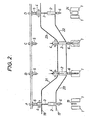
- the molding unit illustrated is part of a blow molding apparatus comprising a series of such units, mounted radially on a support, not shown, which is preferably rotatable.
- Each molding unit comprises a blowing mold 1, a blowing device 2, a longitudinal drawing rod 3, a drive sleeve 4 for the drawing rod, and a stop 5.
- the blowing mold 1 is of the conventional type and generally consists of two complementary half-molds.
- the blowing device 2 is also of the conventional type, apart from the fact that the drawing rod 3, which is coaxial with it, can slide freely through it.
- the blowing device comprises a blowing nozzle 6, a conduit 7 for supplying the expansion fluid, a housing 8 for distributing the expansion fluid, a spring device 9 tightly applying the blowing nozzle 6 against the mouth of the blow mold 1 during the blow molding of the preforms, and a sealing device 10 preventing the loss of expansion fluid between the distribution box 8 and the drawing rod 3t
- the blowing device is controlled by a profiled cam 17 (FIGS. 2 and 3) which brings this device into close contact with the mouth of the mold 1 when the latter is closed and contains a preform 19 to be blow molded and which discards this device of the mouth of the mold 1 after the blow molding operation.
- a profiled cam 17 FIGS. 2 and 3
- the end of the drawing rod 3 which exerts the pushing force on the bottom of the preforms is profiled so as to minimize any risk of damage to the bottom of the preforms; this end is therefore devoid of sharp angles.
- the driving sleeve 4 (FIG. 1) of the drawing rod 3 encloses the drawing rod 3 proper as well as a control sleeve 11 wedged on the leading end of the drawing rod 3, c ' is this control sleeve which has notches 12 whose profile has the shape of a flattened M.
- the control sleeve 11 which is completely integral with the drawing rod 3 can slide in the cylindrical part 13 of the drive sleeve 4.
- the latter is fitted with calibrated springs 14 and pushers 15 acting on rollers 16 applied by these springs 14 against the hollow of the notches 12 of the control sleeve 11.
- the drive sleeve 4 is actuated by a profiled control cam 18 ( Figures 2 and 3) which governs its movements.
- the stop 5 is constituted by a hollow tube in which the leading end of the drawing rod 3 can be inserted and against the end of which the control sleeve 11 can come into abutment wedged on this drawing rod 3.
- the control cam 18 of the drive sleeve 4 can be shaped in such a way that the longitudinal stretching of the preforms is carried out before or during the final blow molding.
- the control cam 18 of the drive sleeve 4 can, moreover, be designed so as to return this sleeve to its initial position after the stretching and final blowing operations so that the stretching rod 3 is brought back in the starting position for a new cycle.
- the stop 5 can be used to block the leading end of the drawing rod 3 during its ascent. Furthermore, it correctly reintroduces the control sleeve 11 of the drawing rod 3 into the drive sleeve 4 in the case where the latter has come out of the latter due to an accidental overshooting of the predetermined limit value of the thrust force exerted by the drawing rod 3.
- the blowing device 2 gradually approaches the closed mold 1 and the nozzle 6 is applied to the mouth of the mold 1 when the molding unit reaches the end of the inclined parts 20 and 21 of the profiling of the cams 17 and 18.
- the drive sleeve 4 approaches the blowing device 2, which causes the sliding of the drawing rod 3 to through the blowing device 2 and therefore the longitudinal stretching of the preform 19 enclosed in the mold 1.
- the profiling of the section 21 of the cam 18 is designed in such a way that, when the molding unit reaches position B, the desired longitudinal stretch for the preforms 19 is reached.
- the molding unit approaches the inclined parts 22 and 23 of the cams 17 and 18.
- the profiling 23 causes the progressive withdrawal of the drawing rod 3 and the profiling 22 causes the withdrawal of the blowing device 2 with respect to to the mold 1.
- the control sleeve 11 of the drawing rod abuts against the stop 5 and the blowing device 2 as well as the drive sleeve 4 of the drawing rod 3 have returned to their initial position as shown in position D.
- the mold 1 is gradually opened and the molded hollow body 24 is removed from the mold.
- the rollers 16 of the pushers 15 are pushed against the action of the springs 14 and the drive sleeve 4 no longer drives the longitudinal drawing rod 3 via the control sleeve 11.
- the drive sleeve 4 causes, via the control sleeve 11, the descent of the longitudinal stretching rod 3 in the preform 19 until the pushing force exerted by this stretching rod 3 reaches the predetermined value and, at this time , the drive sleeve ceases to drive the drawing rod 3 due to a relative movement between the drive sleeve 13 and the control sleeve 11.
- control sleeve 11 is extracted, in this case, from the cylindrical part 13 of the drive sleeve 4 and the preform is no longer axially stretched.
- control sleeve 11 abuts against the stop 5 during the ascent of the drive unit 13 under the effect of the profiling 23 of the cam 18. This stop retains the drawing rod 3 and forces the control sleeve 11 into the drive sleeve 4 so that all the elements of the device have returned to their initial position when the molding unit is in position D and a new molding cycle can be undertaken.
- the molding units are, for the sake of clarity, represented as if they were moving in a plane, but it is quite obvious that in the case of a rotary apparatus, the molding units can follow a circular path.
- the device according to the invention is particularly suitable for the production of molecularly bioriented hollow bodies: it suffices to use preforms thermally conditioned at a temperature inducing, during drawing, molecular orientation tensions in their constituent material. .
- the preforms used in this case, which can advantageously be provided with a closed hemispherical bottom as described in Belgian patent 826 676 filed on 14.3. 1975 by the Applicant.
- the end of the drawing rod coming into contact with the bottom of the preforms is advantageously of hemispherical shape.
Landscapes
- Engineering & Computer Science (AREA)
- Manufacturing & Machinery (AREA)
- Mechanical Engineering (AREA)
- Blow-Moulding Or Thermoforming Of Plastics Or The Like (AREA)
- Processing And Handling Of Plastics And Other Materials For Molding In General (AREA)
Claims (4)
Priority Applications (1)
| Application Number | Priority Date | Filing Date | Title |
|---|---|---|---|
| AT79200450T ATE1802T1 (de) | 1978-08-24 | 1979-08-13 | Vorrichtung zum warmstrecken von vorformlingen aus thermoplastischem kunststoff beim blasformen. |
Applications Claiming Priority (2)
| Application Number | Priority Date | Filing Date | Title |
|---|---|---|---|
| FR7824756 | 1978-08-24 | ||
| FR7824756A FR2434024A1 (fr) | 1978-08-24 | 1978-08-24 | Dispositif pour l'etirage de preformes en matiere thermoplastique lors de leur moulage par soufflage |
Publications (2)
| Publication Number | Publication Date |
|---|---|
| EP0008481A1 EP0008481A1 (de) | 1980-03-05 |
| EP0008481B1 true EP0008481B1 (de) | 1982-11-17 |
Family
ID=9212107
Family Applications (1)
| Application Number | Title | Priority Date | Filing Date |
|---|---|---|---|
| EP79200450A Expired EP0008481B1 (de) | 1978-08-24 | 1979-08-13 | Vorrichtung zum Warmstrecken von Vorformlingen aus thermoplastischem Kunststoff beim Blasformen |
Country Status (5)
| Country | Link |
|---|---|
| US (1) | US4284397A (de) |
| EP (1) | EP0008481B1 (de) |
| AT (1) | ATE1802T1 (de) |
| DE (1) | DE2964055D1 (de) |
| FR (1) | FR2434024A1 (de) |
Families Citing this family (5)
| Publication number | Priority date | Publication date | Assignee | Title |
|---|---|---|---|---|
| JPS61255832A (ja) * | 1985-05-08 | 1986-11-13 | Kureha Chem Ind Co Ltd | ポリアリ−レンチオエ−テル延伸ブロ−成形容器及びその製造法 |
| FR2798093B1 (fr) * | 1999-09-03 | 2001-11-30 | Sidel Sa | Machine rotative d'etirage-soufflage comportant une commande magnetique de la tige d'etirage |
| FR2863929B1 (fr) * | 2003-12-19 | 2006-02-10 | Sidel Sa | Agencement pour la fixation amovible d'une tige d'etirage sur un coulisseau appartenant a une machine de soufflage et d'etirage d'une preforme |
| FR2912678B1 (fr) * | 2007-02-16 | 2013-02-15 | Sidel Participations | Tuyere pour une machine de fabrication de recipients |
| DE102007049283A1 (de) * | 2007-10-12 | 2009-04-16 | Krones Ag | Reckstangenhalteanordnung |
Family Cites Families (7)
| Publication number | Priority date | Publication date | Assignee | Title |
|---|---|---|---|---|
| US1899238A (en) * | 1930-07-19 | 1933-02-28 | Day J H Co | Dough divider |
| US2001026A (en) * | 1933-04-14 | 1935-05-14 | Day J H Co | Dough divider |
| DE2134003B2 (de) * | 1970-07-10 | 1977-05-05 | Showa Denko KX., Tokio; Nissei Plastics Industrial Co., Ltd., Nagano; (Japan) | Vorrichtung zum herstellen eines hohlkoerpers aus einem thermoplastischen werkstoff durch spritzblasformen |
| US3859019A (en) * | 1973-03-13 | 1975-01-07 | Glacier Industries | Stick insertion apparatus |
| US3977822A (en) * | 1975-03-17 | 1976-08-31 | Monsanto Company | Apparatus for continuous stretch-blow molding |
| AU505338B2 (en) * | 1975-09-10 | 1979-11-15 | The Standard Oil Company | Blow-moulding apparatus for biaxially oriented plastics container |
| US4070428A (en) * | 1976-02-09 | 1978-01-24 | Owens-Illinois, Inc. | Method for blow molding |
-
1978
- 1978-08-24 FR FR7824756A patent/FR2434024A1/fr active Granted
-
1979
- 1979-08-13 AT AT79200450T patent/ATE1802T1/de not_active IP Right Cessation
- 1979-08-13 EP EP79200450A patent/EP0008481B1/de not_active Expired
- 1979-08-13 DE DE7979200450T patent/DE2964055D1/de not_active Expired
- 1979-08-23 US US06/068,955 patent/US4284397A/en not_active Expired - Lifetime
Also Published As
| Publication number | Publication date |
|---|---|
| FR2434024B1 (de) | 1981-01-16 |
| EP0008481A1 (de) | 1980-03-05 |
| FR2434024A1 (fr) | 1980-03-21 |
| DE2964055D1 (en) | 1982-12-23 |
| ATE1802T1 (de) | 1982-12-15 |
| US4284397A (en) | 1981-08-18 |
Similar Documents
| Publication | Publication Date | Title |
|---|---|---|
| EP1324870B1 (de) | Streckblasmaschine mit einer verbesserten steuerung des streckhelfers | |
| EP1261471B1 (de) | Blasformmaschine für behälter, die eine vorrichtung zur orientierung der preforms im werkzeug enthält | |
| CH438688A (fr) | Machine à mouler des flacons en matière thermoplastique | |
| EP2139666A1 (de) | Transfervorrichtung und lineares gerät zur herstellung von behältern | |
| WO2009010505A1 (fr) | Installation pour la fabrication de recipients a partir d'une preforme et procede de commande des moyens de soufflage d'une telle installation | |
| CH633745A5 (fr) | Machine de formage a chaud de pieces en matiere plastique. | |
| EP3057767B1 (de) | Formeinheit zur herstellung von behältern mit einem kompensationsgreifer | |
| FR2798093A1 (fr) | Machine rotative d'etirage-soufflage comportant une commande magnetique de la tige d'etirage | |
| EP0008481B1 (de) | Vorrichtung zum Warmstrecken von Vorformlingen aus thermoplastischem Kunststoff beim Blasformen | |
| EP0239136B1 (de) | Vorrichtung zum Spritzgiessen von rohrförmigen Vorförmlingen aus thermoplastischem Kunststoff | |
| FR2630964A1 (fr) | Procede et dispositif pour le moulage par soufflage d'un corps creux en matiere thermoplastique | |
| CH457812A (fr) | Machine à mouler | |
| EP3131734B1 (de) | Giesseinheit mit formbodenbetätigungseinrichtung auf einer fixen halterung | |
| CA1066864A (fr) | Appareillage pour la production en continu de corps creux orientes en matiere thermoplastique | |
| FR2543880A1 (fr) | Dispositif d'actionnement d'un mandrin de machine de moulage par soufflage de recipients en polymere thermoplastique | |
| EP3173212B1 (de) | Verfahren zur steuerung einer spritzguss-einheit | |
| WO2000064658A1 (fr) | Four de conditionnement thermique pour une installation de fabrication par soufflage de recipients en materiau thermoplastique | |
| EP3787870B1 (de) | Verfahren zur herstellung eines behälters aus thermoplastischem material durch biaxiale streckung | |
| EP3481617B1 (de) | Verfahren zur herstellung eines kunststoffbehälters durch blasformung | |
| EP3546194B1 (de) | Fördervorrichtung, die mit einem sicherheitssystem ausgestattet ist | |
| FR2736582A1 (fr) | Installation pour la fabrication d'ebauches de corps creux en matiere synthetique | |
| EP4261006A1 (de) | Zieh- und kühlstab zur herstellung von behältern | |
| EP4261007A1 (de) | Streckstange zur herstellung von behältern | |
| EP1066950A1 (de) | Verfahren zum Herstellen von Gefässen durch Warmumformen und Vorrichtung dazu | |
| BE861458A (fr) | Machine de moulage |
Legal Events
| Date | Code | Title | Description |
|---|---|---|---|
| PUAI | Public reference made under article 153(3) epc to a published international application that has entered the european phase |
Free format text: ORIGINAL CODE: 0009012 |
|
| AK | Designated contracting states |
Designated state(s): AT BE CH DE FR GB IT LU NL SE |
|
| 17P | Request for examination filed | ||
| ITF | It: translation for a ep patent filed |
Owner name: BARZANO' E ZANARDO MILANO S.P.A. |
|
| GRAA | (expected) grant |
Free format text: ORIGINAL CODE: 0009210 |
|
| AK | Designated contracting states |
Designated state(s): AT BE CH DE FR GB IT LU NL SE |
|
| REF | Corresponds to: |
Ref document number: 1802 Country of ref document: AT Date of ref document: 19821215 Kind code of ref document: T |
|
| REF | Corresponds to: |
Ref document number: 2964055 Country of ref document: DE Date of ref document: 19821223 |
|
| ITTA | It: last paid annual fee | ||
| REG | Reference to a national code |
Ref country code: FR Ref legal event code: CD |
|
| ITPR | It: changes in ownership of a european patent |
Owner name: CAMBIO RAGIONE SOCIALE;SOLVAY |
|
| REG | Reference to a national code |
Ref country code: CH Ref legal event code: PFA Free format text: SOLVAY (SOCIETE ANONYME) |
|
| NLT1 | Nl: modifications of names registered in virtue of documents presented to the patent office pursuant to art. 16 a, paragraph 1 |
Owner name: SOLVAY (SOCIETE ANONYME) TE BRUSSEL, BELGIE. |
|
| EPTA | Lu: last paid annual fee | ||
| EAL | Se: european patent in force in sweden |
Ref document number: 79200450.9 |
|
| PGFP | Annual fee paid to national office [announced via postgrant information from national office to epo] |
Ref country code: LU Payment date: 19950701 Year of fee payment: 17 |
|
| PGFP | Annual fee paid to national office [announced via postgrant information from national office to epo] |
Ref country code: FR Payment date: 19950714 Year of fee payment: 17 |
|
| PGFP | Annual fee paid to national office [announced via postgrant information from national office to epo] |
Ref country code: SE Payment date: 19950717 Year of fee payment: 17 |
|
| PGFP | Annual fee paid to national office [announced via postgrant information from national office to epo] |
Ref country code: BE Payment date: 19950718 Year of fee payment: 17 |
|
| PGFP | Annual fee paid to national office [announced via postgrant information from national office to epo] |
Ref country code: CH Payment date: 19950726 Year of fee payment: 17 |
|
| PGFP | Annual fee paid to national office [announced via postgrant information from national office to epo] |
Ref country code: GB Payment date: 19950802 Year of fee payment: 17 |
|
| PGFP | Annual fee paid to national office [announced via postgrant information from national office to epo] |
Ref country code: AT Payment date: 19950810 Year of fee payment: 17 |
|
| PGFP | Annual fee paid to national office [announced via postgrant information from national office to epo] |
Ref country code: DE Payment date: 19950830 Year of fee payment: 17 |
|
| PGFP | Annual fee paid to national office [announced via postgrant information from national office to epo] |
Ref country code: NL Payment date: 19950831 Year of fee payment: 17 |
|
| PG25 | Lapsed in a contracting state [announced via postgrant information from national office to epo] |
Ref country code: LU Free format text: LAPSE BECAUSE OF NON-PAYMENT OF DUE FEES Effective date: 19960813 Ref country code: GB Effective date: 19960813 Ref country code: AT Effective date: 19960813 |
|
| PG25 | Lapsed in a contracting state [announced via postgrant information from national office to epo] |
Ref country code: SE Effective date: 19960814 |
|
| PG25 | Lapsed in a contracting state [announced via postgrant information from national office to epo] |
Ref country code: CH Effective date: 19960831 Ref country code: BE Effective date: 19960831 |
|
| BERE | Be: lapsed |
Owner name: SOLVAY Effective date: 19960831 |
|
| PG25 | Lapsed in a contracting state [announced via postgrant information from national office to epo] |
Ref country code: NL Effective date: 19970301 |
|
| GBPC | Gb: european patent ceased through non-payment of renewal fee |
Effective date: 19960813 |
|
| REG | Reference to a national code |
Ref country code: CH Ref legal event code: PL |
|
| PG25 | Lapsed in a contracting state [announced via postgrant information from national office to epo] |
Ref country code: FR Effective date: 19970430 |
|
| NLV4 | Nl: lapsed or anulled due to non-payment of the annual fee |
Effective date: 19970301 |
|
| PG25 | Lapsed in a contracting state [announced via postgrant information from national office to epo] |
Ref country code: DE Effective date: 19970501 |
|
| EUG | Se: european patent has lapsed |
Ref document number: 79200450.9 |
|
| REG | Reference to a national code |
Ref country code: FR Ref legal event code: ST |
|
| PLBE | No opposition filed within time limit |
Free format text: ORIGINAL CODE: 0009261 |
|
| STAA | Information on the status of an ep patent application or granted ep patent |
Free format text: STATUS: NO OPPOSITION FILED WITHIN TIME LIMIT |