EP0008352B1 - Winding system for flexible conduits and cables - Google Patents
Winding system for flexible conduits and cables Download PDFInfo
- Publication number
- EP0008352B1 EP0008352B1 EP79102390A EP79102390A EP0008352B1 EP 0008352 B1 EP0008352 B1 EP 0008352B1 EP 79102390 A EP79102390 A EP 79102390A EP 79102390 A EP79102390 A EP 79102390A EP 0008352 B1 EP0008352 B1 EP 0008352B1
- Authority
- EP
- European Patent Office
- Prior art keywords
- conduit
- cable
- vehicle
- sheave
- fairlead
- Prior art date
- Legal status (The legal status is an assumption and is not a legal conclusion. Google has not performed a legal analysis and makes no representation as to the accuracy of the status listed.)
- Expired
Links
- 238000004804 winding Methods 0.000 title description 20
- 230000007935 neutral effect Effects 0.000 claims description 7
- 150000001875 compounds Chemical class 0.000 claims 1
- 230000007257 malfunction Effects 0.000 claims 1
- 230000007246 mechanism Effects 0.000 description 37
- 239000003990 capacitor Substances 0.000 description 5
- 230000001052 transient effect Effects 0.000 description 5
- 239000012530 fluid Substances 0.000 description 4
- 238000005065 mining Methods 0.000 description 4
- 230000009977 dual effect Effects 0.000 description 3
- 238000001816 cooling Methods 0.000 description 2
- 230000003287 optical effect Effects 0.000 description 2
- WVMLRRRARMANTD-FHLIZLRMSA-N ram-316 Chemical compound C1=CCC[C@@]2(O)[C@H]3CC4=CC=C(OC)C(O)=C4[C@]21CCN3C WVMLRRRARMANTD-FHLIZLRMSA-N 0.000 description 2
- 239000007787 solid Substances 0.000 description 2
- 238000010420 art technique Methods 0.000 description 1
- 239000004020 conductor Substances 0.000 description 1
- 230000003247 decreasing effect Effects 0.000 description 1
- 230000000694 effects Effects 0.000 description 1
- 230000005611 electricity Effects 0.000 description 1
- 230000007613 environmental effect Effects 0.000 description 1
- 230000001788 irregular Effects 0.000 description 1
- 230000002093 peripheral effect Effects 0.000 description 1
Images


Classifications
-
- B—PERFORMING OPERATIONS; TRANSPORTING
- B65—CONVEYING; PACKING; STORING; HANDLING THIN OR FILAMENTARY MATERIAL
- B65H—HANDLING THIN OR FILAMENTARY MATERIAL, e.g. SHEETS, WEBS, CABLES
- B65H75/00—Storing webs, tapes, or filamentary material, e.g. on reels
- B65H75/02—Cores, formers, supports, or holders for coiled, wound, or folded material, e.g. reels, spindles, bobbins, cop tubes, cans, mandrels or chucks
- B65H75/34—Cores, formers, supports, or holders for coiled, wound, or folded material, e.g. reels, spindles, bobbins, cop tubes, cans, mandrels or chucks specially adapted or mounted for storing and repeatedly paying-out and re-storing lengths of material provided for particular purposes, e.g. anchored hoses, power cables
- B65H75/36—Cores, formers, supports, or holders for coiled, wound, or folded material, e.g. reels, spindles, bobbins, cop tubes, cans, mandrels or chucks specially adapted or mounted for storing and repeatedly paying-out and re-storing lengths of material provided for particular purposes, e.g. anchored hoses, power cables without essentially involving the use of a core or former internal to a stored package of material, e.g. with stored material housed within casing or container, or intermittently engaging a plurality of supports as in sinuous or serpentine fashion
- B65H75/362—Cores, formers, supports, or holders for coiled, wound, or folded material, e.g. reels, spindles, bobbins, cop tubes, cans, mandrels or chucks specially adapted or mounted for storing and repeatedly paying-out and re-storing lengths of material provided for particular purposes, e.g. anchored hoses, power cables without essentially involving the use of a core or former internal to a stored package of material, e.g. with stored material housed within casing or container, or intermittently engaging a plurality of supports as in sinuous or serpentine fashion with stored material housed within a casing or container
- B65H75/364—Cores, formers, supports, or holders for coiled, wound, or folded material, e.g. reels, spindles, bobbins, cop tubes, cans, mandrels or chucks specially adapted or mounted for storing and repeatedly paying-out and re-storing lengths of material provided for particular purposes, e.g. anchored hoses, power cables without essentially involving the use of a core or former internal to a stored package of material, e.g. with stored material housed within casing or container, or intermittently engaging a plurality of supports as in sinuous or serpentine fashion with stored material housed within a casing or container the stored material being coiled
-
- B—PERFORMING OPERATIONS; TRANSPORTING
- B65—CONVEYING; PACKING; STORING; HANDLING THIN OR FILAMENTARY MATERIAL
- B65H—HANDLING THIN OR FILAMENTARY MATERIAL, e.g. SHEETS, WEBS, CABLES
- B65H51/00—Forwarding filamentary material
- B65H51/02—Rotary devices, e.g. with helical forwarding surfaces
- B65H51/04—Rollers, pulleys, capstans, or intermeshing rotary elements
- B65H51/06—Rollers, pulleys, capstans, or intermeshing rotary elements arranged to operate singly
-
- H—ELECTRICITY
- H02—GENERATION; CONVERSION OR DISTRIBUTION OF ELECTRIC POWER
- H02G—INSTALLATION OF ELECTRIC CABLES OR LINES, OR OF COMBINED OPTICAL AND ELECTRIC CABLES OR LINES
- H02G11/00—Arrangements of electric cables or lines between relatively-movable parts
- H02G11/02—Arrangements of electric cables or lines between relatively-movable parts using take-up reel or drum
-
- B—PERFORMING OPERATIONS; TRANSPORTING
- B65—CONVEYING; PACKING; STORING; HANDLING THIN OR FILAMENTARY MATERIAL
- B65H—HANDLING THIN OR FILAMENTARY MATERIAL, e.g. SHEETS, WEBS, CABLES
- B65H2701/00—Handled material; Storage means
- B65H2701/30—Handled filamentary material
- B65H2701/33—Hollow or hose-like material
Definitions
- the fairlead position signal may be combined with a vehicle speed signal to control the hydraulic motor 26.
- the speed of the vehicle 12 may be measured by a conventional tachometer 104 and applied to a voltage follower operational amplifier 106 through potentiometer 108.
- the voltage on the wiper of potentiometer 108 is filtered by capacitor 110.
- the voltage at the output of amplifier 106 which is proportional to vehicle speed, and the voltage at the output of amplifier 96 which is proportional to fairlead position, are applied to summing amplifier 112 through resistors 114, 116, respectively.
- the sequentially generated pulses from NAND gate 150 are applied to the reset terminal of a counter 156 through NAND gate 158 when NAND gate 158 is, enabled as explained hereinafter.
- NAND gate 158 When NAND gate 158 is disabled, a logic "1" at the output of NAND gate 158 holds the counter 156 in its reset condition.
- the counter 156 is normally incremented by clock pulses received from a conventional oscillator 160.
- One of the outputs of the clock 156 is applied to NAND gate 162 through switches 164 to apply the brakes of the vehicle as explained hereinafter.
Landscapes
- Storing, Repeated Paying-Out, And Re-Storing Of Elongated Articles (AREA)
- Tension Adjustment In Filamentary Materials (AREA)
- Fittings On The Vehicle Exterior For Carrying Loads, And Devices For Holding Or Mounting Articles (AREA)
- Electric Cable Arrangement Between Relatively Moving Parts (AREA)
Description
- This invention relates to storage mechanisms for flexible conduits and cables, and more particularly, to a vehicle mounted system for winding a flexible conduit or cable in a horizontal coil and automatically extending and retrieving cable responsive to vehicle movement.
- Vehicles which are electrically powered through a multi-conductor umbilical chord are commonly used in underground mines. These vehicles are generally load-haul and dump type mining machines. One problem with such vehicles is the need to extend the cable as the vehicle moves forwardly and retract cable as the vehicle moves rearwardly. This function has generally been accomplished in the past by winding the cable on a reel or drum which is rotatably mounted on a transverse horizontal axis. The power is transferred from the cable to the vehicle drive motor through slip rings such as utilized by conventional AC motors. The slip rings must be custom designed to fit within the relatively small available volume. The reel is generally powered by an electric or hydraulic motor. The hydraulically powered varieties are generally either dual pressure systems or constant tension systems.
- The dual pressure system continuously applies a torque to the reel, but the torque is lower for cable extension or a stationary condition than for cable retrieval. For proper functioning of the system the low torque setting must be large enough to keep excessive cable sag or slack from developing. The minimum cable tension is 100 pounds.
- The constant tension system applies a constant torque to the reel. The value of the torque is not critical, but again it must be large enough to keep slack or sag from developing in the cable. The minimum cable tension for the constant tension system is 150 pounds. These conventional reel systems exhibit many problems, which are alleviated by the inventive cable winding system. A principal problem with the prior art technique is the need to employ slip rings which quickly deteriorate in the severe environmental conditions of a mine. Additionally, the high inertia of the reel and particularly the cable wound thereon reduces the transient response of the cable retracting and extending system. Good transient response can only be maintained, then, by providing a fairly high cable tension. Yet, a relatively high cable tension in itself causes problems. As the cable is wound on the reel with a tension, the inward force exerted by the cable on the reel continues to build up thereby preventing the cable from being adequately cooled and excessively compressing the underlying cable. Also, the cable often catches on irregular contours in a mine, and the cable tension causes violent whipping of the cable as the cable is released, thereby posing a serious safety hazard. Cable whipping also occurs when the vehicle stops or reverses direction suddenly, although this problem is less severe with the constant tension system than the dual pressure system.
- Another problem with conventional reel systems is that they must receive cable from the rear so that the cable is often severely damaged by backing over the cable with the vehicle. For these reasons, conventional vehicle mounted cable storage devices have not been entirely satisfactory.
- Another approach to the problem of extending, retracting and storing umbilical cable in a mining vehicle is described in U.S. Patent No. 3,990,551 issued to Jamison et al. The Jamison et al. device includes a pair of selectively driven rollers engaging the cable therebetween. The rollers convey the cable to and from a rectangular storage box through a slot without guiding the cable in a specific arrangement. A constant torque is applied to the rollers thereby maintaining the tension in the cable constant. Thus the Jamison et al. device does not solve most of the above mentioned problems. Other vehicle mounted devices for retracting and storing cable utilize a rotatably mounted guide arm for guiding the cable from a powered sheave to a coil in a cable storage area. The inlet of the guide arm is positioned along the axis of the coil at the outlet of the powered sheave. An example of this device is described in DE-B-1,168,692. The principal disadvantage of this device is that the guide arm is coupled to the powered sheave so that they move in unison. However, the relationship between the speed of the cable through the guide arm and the rotational velocity should not be fixed, particularly where the coil contains a large number of wraps.
- The invention as claimed is intended to alleviate these problems by a powered driven mechanism for applying either a constant axial force to a cable or flexible conduit or an axial force having a magnitude and direction determined by a conduit control signal. A generally cylindrical conduit container receives the conduit from the drive mechanism through a guide arm which arranges the conduit in a generally cylindrical coil. The guide arm has a first end positioned adjacent a conduit port of the drive mechanism and a second end facing radially outwardly and circumferentially within the conduit container. The guide arm is rotatably mounted about an axis extending through the centers of both the conduit coil and the conduit port of the drive mechanism so that as cable is drawn through the drive mechanism the first end of the guide arm remains adjacent the conduit port while the second end of the guide arm moves circumferentially within the conduit container to arrange the conduit in a coil. The guide arm is mounted for free rotation so that its speed of rotation is independent of the speed of the cable through the guide arm. As a result, the winding system is capable of operating even where multiple wraps of the coil overlap each other. The conduit extends from a point external of the vehicle to the drive mechanism through a fairlead which may pivot about a horizontal axis responsive to vehicle movement. The angle of the fairlead may be measured and utilized to actuate the drive mechanism to either retract or extend conduit responsive to vehicle movement. In order to provide good transient response without allowing excessive movement of the fairlead a feedback signal indicative of fairlead angle may be summed with the output of a tachometer to bias the control system in a conduit winding or unwinding condition responsive to vehicle movement. Alternatively, the drive mechanism may apply a constant tension to the conduit. The drive mechanism, which is preferably a powered sheave, may be pivotally mounted about a vertical axis extending through both the conduit port of the drive mechanism and the rotational axis of the guide arm in order to allow conduit to extend to the vehicle from a variety of directions.
- The invention provides a cable winding system which is capable of retracting and extending cable from a vehicle without maintaining a significant tension on the cable and has a relatively good transient response so that the cable winding mechanism is capable of responding to sudden changes in velocity. The cable is wound in a cylindrical configuration without placing the cable under tension in order to facilitate convection cooling of the cable and to preserve cable life. `
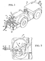
- Figure 1 is an isometric view of a mining vehicle with the inventive cable or conduit winding system installed thereon.
- Figure 2 is a top plan view of the conduit winding system.
- Figure 3 is a cross-sectional view of the conduit winding system taken along the line 3-3 of Figure 1.
- Figure 4 is a schematic of the control circuitry for the conduit winding system.
- Figure 5 is a schematic of the hydraulic mechanisms for the conduit winding system.
- Figure 6 is a cross-sectional view of the conduit drive mechanism taken along the line 6-6 of Figure 3.
- Figure 7 is a cross-sectional view of an alternative embodiment of a conduit drive mechanism allowing the drive mechanism to exert a greater force on the cable.
- The
conduit winding system 10, as illustrated in Figs. 1 and 2 installed on aconventional mining vehicle 12, is adapted to extend and retract a length of electrical conduit orcable 14 responsive to vehicle movement. Although thesystem 10 is described herein for use with cable, it may also be used with conduits for fluid as well as electricity. Consequently, the term "conduit" as used herein is intended to apply to all flexible, elongated members including cables and pipelines. Thewinding system 10 includes a generally circular or ovalcable storage area 16, adrive mechanism 18 for selectively applying an axial force to thecable 14, a fairlead 20 for guiding and supporting thecable 14 between thedrive mechanism 18 and a power source external of thevehicle 12, and aguide arm 22 for guiding thecable 14 between thedrive mechanism 18 andcable storage area 16 and positioning thecable 14 in a cylindrical coil. Thefairlead 20 is pivotally secured to acylindrical cable guide 24 so that as thevehicle 12 moves away from the cable, the fairlead 20 pivots upwardly toward the deployed cable and away from the vehicle causing cable to be extended. Similarly, as thevehicle 12 moves toward the deployed cable, the fairlead 20 pivots through a vertical position toward the cable and vehicle casing cable to be retracted. Thus, as illustrated in Fig. 1, forward movement of thevehicle 12 causes the fairlead 20 to pivot rearwardly to extend cable, and rearward movement of thevehicle 12 causes the fairlead 20 to pivot forwardly to retract cable. It will be understood, however, that thecable 14 may extend from a point forwardly or to one side of the vehicle so that forward movement of thevehicle 12 may cause cable to be retracted and rearward movement of thevehicle 12 may cause cable to be extended. - As explained hereinafter, the angle of the
fairlead 20 is measured and applied to control circuitry for selectively actuating thedrive mechanism 18 to retract or extendcable 14. Thedrive mechanism 18 is powered by a conventionalhydraulic motor 26 connected to ahydraulic servo valve 27 throughconduits 28. The end of thecable 14 is anchored at 30 to the cylindrical sidewalls of thecable storage area 16. Since thecable 14 is fixedly anchored to thevehicle 12, conventional slip rings or similar devices are not required. Since thecable 14 is not wound on a reel, the inertia effect of thecable 14 is minimal, thus insuring good transient response. - The
drive mechanism 18 is rotatably supported through ahinge 32 allowing thedrive mechanism 18 to rotate about a vertical axis in order to receivecable 14 from a variety of points around thevehicle 12 in order to position thecable 14 away from the wheels of the vehicle thereby reducing cable damage. Theguide arm 22 is rotatably supported about a vertical axis so that theguide arm 22 rotates as cable is retracted or extended by thedrive mechanism 18. The rotational axes of thehinge 32 and theguide arm 22 are common to each other so that the position of the opening of theguide arm 22 with respect to a cable port for thedrive mechanism 18 remains fixed as thedrive mechanism 18 and guide arm"22 rotate. - The internal structure of the inventive cable winding mechanism is illustrated in further detail in Fig. 3.
Cable 14 enters thefairlead 20 where it is supported by forward, rear andtransverse rollers fairlead 20 is pivotally secured to acylindrical cable guide 24 byconventional bearings 46. Apotentiometer 50 rotates with thefairlead 20 to provide an electrical indication of the fairlead position in order to control the drive mechanism as explained in greater detail hereinafter. Thecable guide 24 is composed of two sections, a lowercable guide section 24a and an uppercable guide section 24b. Thelower section 24a is rotatably secured to the uppercable guide section 24b by aconventional bearing mechanism 48 which allows the lowercable guide section 24a to rotate with respect to the uppercable guide section 24b about a vertical axis. Thebearing mechanism 48 allows thecable 14 to extend from thefairlead 20 at a variety of azimuths even when the rotational position of thedrive mechanism 18 is fixed. In the normal stationary condition thecable 14 assumes a natural catenary configuration as it extends to the ground with thefairlead 20 assuming an offset angle from the vertical that corresponds to the desired catenary of the cable at rest. Any forward or reverse movement of the vehicle changes the position of thefairlead 20 to produce a positive or negative error signal depending upon whether the movement tends to increase or decrease the angle of the catenary of the cable passing through thefairlead 20. - The
cable 14 extends through theupper cable guide 24b and engages a rotatably mountedsheave 52 having anaxle 54 connected to the hydraulic motor 26 (Figs. 1 and 2). The periphery of thesheave 52 may have a variety of cross-sectional shapes, but the embodiment illustrated in Figs. 3 and 6 utilizes a peripheral edge having a substantially rectangular shape. Thecable 14 is positioned between thesheave 52 and a plurality of freelyrotatable guide rollers 56. Therollers 56 loosely engage thecable 14 since they are not pressure rollers but are provided to prevent thecable 14 from bowing outwardly when thesheave 52 rotates counterclockwise as illustrated in Fig. 3. Thecable 14 extends along the periphery of thesheave 52 to a pair ofpressure rollers 58 which resiliently bias thecable 14 against thesheave 52. Therollers 58 are carried byhydraulic rams 60 which, as explained hereinafter, apply a constant force to thecable 14 but allow therollers 58 to move away from thesheave 52 to accommodate splices in thecable 14 having a relatively large diameter. - Under some conditions the friction between the
cable 14 andsheave 52 may be insufficient for optimum performance thereby allowing thecable 14 to slide or slip on the periphery of thesheave 52. Under these circumstances the alternative embodiment 18' of the conduit drive mechanism illustrated in Fig. 7 may be employed. In this embodiment 18' thecable 14 is gripped between afixed flange 300 integral with asheave 302 and amovable flange 304. Themovable flange 304 is mounted on ahub 306 which is, in turn, mounted on adrive shaft 308 through abearing 310. Thebearing 310 allows theflange 304 to freely pivot about the axis of theshaft 308 so that theflange 304 can contact thecable 14 along the upper periphery of thesheave 302. The upper periphery of thesheave 302 is biased against thecable 14 by apressure shoe 312 containing aroller 314 for allowing circumferential movement of themovable flange 304 with respect to thepressure shoe 312. Thepressure shoe 312 is biased against theflange 304 by a conventionalhydraulic ram 316. A plurality of circumferentially spacedguides 318 carried by thesheave 302 extend through apertures in theflange 304 to insure that theflange 304 rotates with thesheave 302. In operation thehydraulic motor 26 selectively rotates theshaft 308 in either direction which in turn rotates thesheave 302 through ahub 320 and theflange 304 through thebearing 310. Theram 316 continuously urges thepressure shoe 312 against theflange 304 through theroller 314 so that the cable is gripped between theflanges -
Cable 14 is guided from acable port 61 of thesheave 52 to thecable storage area 16 through theguide arm 22. Theguide arm 22 is formed in a generally S-shaped configuration when viewed from both the top, as illustrated in Fig. 2, and the side, as illustrated in Fig. 3. Theguide arm 22 is mounted on acylindrical support 62 having an annular flange which is bolted to a circular plate 64. The plate 64 is mounted on ashaft 66 which is rotatably supported in a frustoconically shapedbase 68 by bearings 70. The upper end of theguide arm 22 is tangent to the periphery of thesheave 52 and the axis of rotation of thearm 22 is tangent to the periphery of thesheave 52. Consequently, the upper end of thesupport arm 22 remains fixed with respect to thecable port 61 and the periphery of thesheave 52 as theguide arm 22 rotates. Similarly, thehinge 32, which includes apin 72 extending through apertures indrive mechanism flanges 74 andsupport flanges 76, has an axis of rotation which is common to the rotational axis of theguide arm 22. Consequently, the upper end of theguide arm 22 remains fixed with respect to thesheave 52 as thedrive mechanism 18 pivots. The position of thedrive mechanism 18 is normally fixed by a locking bolt 78 extending through theflange 76 intoflange 74. - In operation, when the vehicle moves away from the cable, the increased tension on
cable 14 causes thefairlead 20 to pivot toward the direction from which the cable extends. As explained hereinafter, pivotal movement of thefairlead 20 actuates thehydraulic motor 26 thereby causing thesheave 52 to rotate counterclockwise in order to extend cable from thefairlead 20. Thefairlead 20 then pivots downwardly to the desired offset for a neutral position. As thesheave 52 rotates counterclockwise, the guide rollers 56 (Fig. 6) prevent thecable 14 from buckling while thepressure rollers 58 cause thecable 14 to frictionally engage the periphery of thesheave 52. Ascable 14 is drawn from theguide arm 22 theguide arm 22 rotates clockwise thereby removingcable 14 from thecable storage area 16. - Alternatively, as the vehicle moves toward the cable, the
fairlead 20 pivots away from the direction from which the cable extends thereby actuating thehydraulic motor 26 to rotate thesheave 52 clockwise.Cable 14 is then drawn inwardly through thefairlead 20 causing thefairlead 20 to pivot rearwardly toward its neutral position. As thesheave 52 continues to rotate clockwise, theguide arm 22 rotates counterclockwise thereby windingcable 14 in thecable storage area 16. Thecable 14 is relatively loosely wound in thecable storage area 16 thereby allowing good convection cooling of thecable 14 and freeing the cable from damaging forces exerted on each other. When a cable splice having a relatively large dimension is encountered, thepressure rollers 58 are permitted to move away from thesheave 52 while the splice passes therebetween. - Alternatively, the
hydraulic motor 26 may apply a constant torque to thesheave 52 in a cable retracting direction to impart a constant tension to the cable. In this configuration, thefairlead 20 is not instrumented, and the cable is extended and retracted responsive to vehicle movement as in the conventional drum mounted system. Even this simplified alternative system is a great improvement over prior art systems since it eliminates slip rings, high reel inertial and high cable storage tension of conventional reel systems. - One advantageous property of the inventive cable winding mechanism is its adaptability to various size cables. The system may be modified to handle a differing cable diameter by simply unbolting the
lower cable guide 24a andfairlead 20 from theupper cable guide 24b at thebearing mechanism 48 replacing thesheave 52 with one having a different transverse dimension, and replacing theguide arm 22 by unbolting theguide arm support 62 from thesupport plate 66. - The circuitry for controlling the operation of the cable winding system is illustrated in Fig. 4. The circuitry includes
sheave control circuitry 89 receiving the output of thepotentiometer 50 connected to thefairlead support pin 46. Thepotentiometer 50 is connected to plus and minus supply voltages throughvariable resistors 90, 92 which may be adjusted to control the magnitude of the signal on the wiper of thepotentiometer 50 for a given movement of thefairlead 20. Thus, by decreasing the value of resistor 90 and increasing the value ofresistor 92, the voltage at the wiper ofpotentiometer 50 will be larger for a given upward movement of the wiper than for the same movement of the wiper downwardly. Since the wiper of thepotentiometer 50 is grounded, the voltage on the wiper is always zero for a neutral fairlead position. The wiper ofpotentiometer 50 is connected to anoperational amplifier 94 arranged as a voltage follower. The output of theamplifier 94 is amplified byoperational amplifier 96 having a gain which is proportional to the ratio of the resistance ofpotentiometer 98 to the resistance ofresistor 100. In accordance with good design practice, the resistance ofresistor 102 is approximately equal to the parallel combination ofresistances amplifier 96 is thus a positive or negative voltage proportional to the rearward or forward pivotal movement of thefairlead 20. - In accordance with an optional, unessential feature of the invention, the fairlead position signal may be combined with a vehicle speed signal to control the
hydraulic motor 26. The speed of thevehicle 12 may be measured by aconventional tachometer 104 and applied to a voltage followeroperational amplifier 106 throughpotentiometer 108. The voltage on the wiper ofpotentiometer 108 is filtered bycapacitor 110. The voltage at the output ofamplifier 106 which is proportional to vehicle speed, and the voltage at the output ofamplifier 96 which is proportional to fairlead position, are applied to summingamplifier 112 throughresistors Amplifier 112 produces a voltage across acurrent sensing resistor 118 which is proportional to the sum of the vehicle speed voltage at the output of theamplifier 106 and the fairlead position voltage at the output of theamplifier 96. The magnitude of the voltage acrosscurrent sensing resistor 118 for a given vehicle speed voltage or fairlead position voltage is determined by the ratio of the resistance ofpotentiometer 120 to theresistance resistor 122 is approximately equal to the resistance of the parallel combination ofresistors current sensing resistor 118 is proportional to the current therethrough. All of the current flowing throughresistor 118 essentially flows throughresistor 124 andsolenoid coil 126 when theswitch 128 is in either the test or operate modes as explained hereinafter. Theservo coil 126 controls the operation of thehydraulic motor 26 as explained hereinafter. The magnitude and direction of the current flowing through theservo coil 126 is thus proportional to the fairlead position voltage at the output ofamplifier 94 or, where the vehicle speed option is employed, the sum of the fairlead position voltage, and the vehicle speed signal at the output of amplifier 1.06. At high vehicle speeds the voltage at the output ofamplifier 112 must be relatively large. Without a signal proportional to vehicle speed, a larger pivotal movement of thefairlead 20 would be required to generate a sufficiently large signal at the output ofamplifier 94. Alternatively, the loop gain of the system could be greatly increased, but this could introduce instability problems. The vehicle speed signal thus serves as a rough approximation of the required current through thecoil 126 while slight corrective movements of thefairlead 20 produce a small corrective signal at the output of theamplifier 94. In most applications, however, the vehicle speed feedback option is not required. - The control system for the inventive cable winding system also includes failsafe circuitry 1.29 for applying the brakes of the vehicle when either the
sheave 52 is unable to rotate as the vehicle moves or the supply ofcable 14 in thestorage area 16 falls to a predetermined value. The rotational velocity of thesheave 52 is measured by a speed sensor as illustrated in Fig. 6. Thesensor 130 includes ahub 132 secured to the shaft of the hydraulic motor by abolt 134. Thehub 132 has integrally formed therein aflange 136 containing a plurality of circumferentially space apertures. Theflange 136 extends between asensing head 138 having an optical source such as aphotodiode 140 and an optical sensor such as aphototransistor 142. Thus, as thesheave 52 rotates, light is alternately received by thephototransistor 142 from thephotodiode 140 through the apertures inflange 136. - With reference, once again, to Fig. 4, current flows through the
photodiode 140 through current limitingresistor 144, and current flows throughphototransistor 142 andresistor 146 when light fromphotodiode 140 reaches phototransistor 142 through the apertures inflange 136. Thus, when thesheave 52 is rotating, a plurality of pulses are sequentially applied toNAND gate 148.NAND gate 148, in combination withNAND gate 150,capacitor 152 andresistor 154, form a one-shot which produces a pulse having a duration determined by the RC time constant ofresitor 154 andcapacitor 152 at the end of each pulse at the input ofNAND gate 148. The sequentially generated pulses fromNAND gate 150 are applied to the reset terminal of acounter 156 throughNAND gate 158 whenNAND gate 158 is, enabled as explained hereinafter. WhenNAND gate 158 is disabled, a logic "1" at the output ofNAND gate 158 holds thecounter 156 in its reset condition. Thecounter 156 is normally incremented by clock pulses received from aconventional oscillator 160. One of the outputs of theclock 156 is applied toNAND gate 162 throughswitches 164 to apply the brakes of the vehicle as explained hereinafter. -
NAND gate 158 is disabled to allow theclock 156 to increment by the output ofthreshold circuitry 166. Basically, thethreshold circuitry 166 receives the hydraulic motor command signal from the output ofamplifier 96 and determines whether the command signal exceeds a predetermined value in either the clockwise or counterclockwise direction. The command signal is applied tocomparators resistor dividers amplifier 168 thus detects a positive command signal while theamplifier 170 detects a negative command signal. The output ofcomparator 168 is applied toNAND gate 180 throughresistor 182. The output ofcomparator 170 is applied toNAND gate 180 throughNAND gate 184 andresistor 186. When the command signal is close to zero volts the output ofcomparator 168 is positive and the output ofcomparator 170 is negative. The positive voltage at the output ofcomparator 168 represents a logic "1" applied toNAND gate 180, and the negative output ofcomparator 170 is divided throughresistor 186,diode 190, resistor 192 connected to ground and resistor 194 connected to positive voltage supply so that the input toNAND gate 184 is logic "0" thereby producing a "1" at its output. Consequently, the output ofNAND gate 180 is logic "0" which disablesNAND gate 158 and continuously applies a "1" to the reset terminal ofcounter 156 in order to prevent thecounter 156 from incrementing. When the hydraulic motor command signal at the output ofamplifier 96 exceeds a predetermined positive threshold the output ofamplifier 168 goes negative thereby producing a "0" to its input toNAND gate 180 so thatNAND gate 158 is enabled by the "1" at the output ofNAND gate 180.Counter 156 is then allowed to increment between pulses fromNAND gate 150, and if thesheave 52 has not rotated at a predetermined velocity, one of the outputs of thecounter 156 will go high before thecounter 156 is reset at the trailing edge of light transmitted from thephotodiode 140 to thephototransistor 142. When the hydraulic motor command signal fromamplifier 96 goes negative above a predetermined value, the output ofamplifier 170 goes positive until the input toNAND gate 184 is at logic "1" at which point the "0" at the output ofNAND gate 184 produces a "1" " at the output ofNAND gate 180 which enablesNAND gate 158 to allow counter 156 to begin incrementing. - In either the test or operate modes, the input to
NAND gate 200 is connected to ground throughresistor 202 thereby producing a "1" at the output ofNAND gate 200 which continuously enablesNAND gate 162 andNAND gate 204. When one of the outputs ofcounter 156 as selected byswitches 164 goes high responsive to thesheave 52 being unable to rotate a sufficient distance responsive to a command signal above a predetermined value, the "0" at the output ofNAND gate 162 is twice inverted byNAND gates NAND gate 204 to produce a "0" at the output ofinverter 210 which actuates a solid-state relay 212. The solid-state relay 212 applies a signal through acoil 214 of the vehicle emergency brake. In the standby mode, a logic "1" is applied toNAND gate 200 through resistor 218 thereby producing a "0" at the output ofNAND gate 200 which also applies the emergency brake through solid-state relay 212. - In the operate mode, as selected by mode select switch 226, the left side of a 25
foot limit switch 230 and a tenfoot limit switch 232 are grounded. The limit switches 230, 232 are adapted to close when 25 feet and 10 feet, respectively, of cable remain in thecable storage area 16. When the 25foot limit switch 230 is closed, a "1" at the output of NAND gate 234 is inverted by inverter 236 to produce a "0" which actuates thecoil 238 of an alarm throughsolid state relay 240. The output of NAND gate 234 is normally held at "0" by the logic "1" voltage level at its input produced byresistor divider 242, 244.Capacitor 246 is provided to delay actuation of the horn for a short period afterswitch 230 is closed. When the cable remaining in thecable storage area 16 reaches the 10 foot limit,switch 232 is actuated thereby producing a "1" at the output ofNAND gate 206 which actuates the emergency brake through a solid-state relay 212 in the same manner that the brake is actuated byNAND gate 162. The input toNAND gate 206 is normally held at a logic "1" voltage level byvoltage divider resistors capacitor 252 delaying the actuation of the brakes for a predetermined period after the 10foot limit switch 232 closes. In the test mode, the left side oftest switches switches - The
threshold circuit 166 also relieves the load on the hydraulic pump driving thehydraulic motor 26 when thesheave 52 is stationary as indicated by a logic "0" at the output ofNAND gate 180. The "0" at the output ofNAND gate 180 is applied to asolid state relay 266 causing current to flow through thecoil 268 of a solenoid valve to connect the output of the hydraulic pump to the return line. - A schematic of the hydraulic system for the
hydraulic motor 26 and pressure roller rams 60 is illustrated in Fig. 5. Hydraulic fluid stored in areservoir 270 is pressurized by conventionalhydraulic pump 272 and applied to aservo valve 274 having itscontrol coil 126 connected to the hydraulic motor control circuitry illustrated in Fig. 4. Thehydraulic motor 26 is connected to the output of theservo valve 274 so that the direction and magnitude of fluid flow through thehydraulic motor 26 is proportional to the magnitude and direction of the current through the servovalve control coil 126. Thehydraulic cylinders 60 connected to the pressure rollers 58 (Fig. 3) also receive pressurized hydraulic fluid from thehydraulic pump 272 and are connected to thereservoir 270 through a pressure reducing valve with built-inrelief 276 which allows the pressure rollers to retract and accommodate a splice while retaining a relatively constant force against thecable 14 andsheave 52. When thesheave 52 is stationary, current flows through asolenoid valve coil 268 as explained above. Thecoil 268 actuates a valve 280 to connect the output line of thepump 272 to the return line to prevent thepump 272 from laboring. - In the constant tension alternative system the
hydraulic motor 26 is coupled directly to thehydraulic pump 272 so that themotor 26 applies a constant torque to thesheave 52.
Claims (11)
Applications Claiming Priority (2)
| Application Number | Priority Date | Filing Date | Title |
|---|---|---|---|
| US05/923,967 US4258834A (en) | 1978-07-12 | 1978-07-12 | Winding system for flexible conduits and cables |
| US923967 | 1978-07-12 |
Publications (2)
| Publication Number | Publication Date |
|---|---|
| EP0008352A1 EP0008352A1 (en) | 1980-03-05 |
| EP0008352B1 true EP0008352B1 (en) | 1983-01-19 |
Family
ID=25449531
Family Applications (1)
| Application Number | Title | Priority Date | Filing Date |
|---|---|---|---|
| EP79102390A Expired EP0008352B1 (en) | 1978-07-12 | 1979-07-11 | Winding system for flexible conduits and cables |
Country Status (10)
| Country | Link |
|---|---|
| US (1) | US4258834A (en) |
| EP (1) | EP0008352B1 (en) |
| JP (1) | JPS5513700A (en) |
| AU (1) | AU527114B2 (en) |
| CA (1) | CA1126356A (en) |
| DE (1) | DE2964531D1 (en) |
| DK (1) | DK292079A (en) |
| FI (1) | FI792190A7 (en) |
| NO (1) | NO148012C (en) |
| ZA (1) | ZA793516B (en) |
Families Citing this family (29)
| Publication number | Priority date | Publication date | Assignee | Title |
|---|---|---|---|---|
| EP0084606A1 (en) * | 1982-01-04 | 1983-08-03 | Western Gear Corporation | Cable pinching sheave |
| DE3209294A1 (en) * | 1982-03-13 | 1983-09-22 | M.A.N. Maschinenfabrik Augsburg-Nürnberg AG, 4200 Oberhausen | RAILWAY UNDERGROUND VEHICLE |
| JPS617080U (en) * | 1984-06-19 | 1986-01-16 | 富士通電装株式会社 | Storage drawer guide mechanism for external connection cables inside the device |
| FR2575874B1 (en) * | 1985-01-07 | 1987-03-20 | Framatome Sa | DEVICE FOR WINDING AND UNWINDING A CABLE WITH ONE END PROVIDING ELECTRICAL CONTACT WITH A FIXED INSTALLATION |
| CA1336544C (en) * | 1987-12-03 | 1995-08-08 | Stockbridge Manufacturing, Inc. | Portable device for storing an endless metallic or fiber-optic cable |
| US4871127A (en) * | 1987-12-03 | 1989-10-03 | Clark Albert L | Portable device for storing an endless metallic or fiber-optic cable |
| FI885695A7 (en) * | 1988-12-08 | 1990-06-09 | Tampella Oy Ab | SLANG- OCH KABELTRUMANORDNING VID BERGBORRNINGSANORDNING. |
| ATE120051T1 (en) * | 1989-11-08 | 1995-04-15 | Fladung Gmbh Manfred | CABLE WINDING DEVICE. |
| US5419508A (en) * | 1993-07-26 | 1995-05-30 | Pierce; Steve | Cable winding device for electrically powered mining vehicles |
| WO1995031392A1 (en) * | 1994-05-11 | 1995-11-23 | Plumettaz S.A. | Method and device for storing rolled-up cables and the like |
| US5911381A (en) * | 1994-05-11 | 1999-06-15 | Plumettaz As | Stocking device for coilable elements and method of use |
| FI100039B (en) * | 1996-02-02 | 1997-08-29 | Tamrock Loaders Oy | Method and arrangement for controlling the unrolling and unloading of a cable of an electric vehicle |
| SE507788C3 (en) * | 1996-11-28 | 1998-08-10 | Maillefer Nokia Oy | Towing device carries a cable handling system |
| JPH1182417A (en) * | 1997-09-01 | 1999-03-26 | Mitsubishi Heavy Ind Ltd | Fluid servo motor device |
| US6783430B1 (en) | 1997-09-01 | 2004-08-31 | Mitsubishi Heavy Industries, Ltd. | Grinding apparatus using fluid servomotor |
| US5887815A (en) * | 1997-11-03 | 1999-03-30 | Pierce; Steve | Cable winding device for electrically powered mining vehicles |
| FI117359B (en) * | 2004-01-16 | 2006-09-15 | Sandvik Tamrock Oy | Arrangement for data transmission in mine and cable drum |
| US8989929B2 (en) * | 2010-01-22 | 2015-03-24 | Joy Mm Delaware, Inc. | Device for reducing the likelihood of damage to a trailing cable |
| CA2734278A1 (en) * | 2010-03-17 | 2011-09-17 | 9019-8813 Quebec Inc. | Cable handling system |
| US9601880B2 (en) | 2011-11-08 | 2017-03-21 | Ortronics, Inc. | Cable assemblies and associated systems and methods |
| WO2014151259A1 (en) * | 2013-03-15 | 2014-09-25 | Ortronics, Inc. | Cable assemblies, methods and systems |
| US10322868B2 (en) | 2013-03-15 | 2019-06-18 | Ortronics, Inc. | Cable assembly dispenser systems and associated methods |
| PL2937467T3 (en) * | 2014-04-22 | 2017-08-31 | Sandvik Mining And Construction Oy | Anti-slip method and anti-slip system for an electric loader used particularly in mines and excavations and a mining loader |
| WO2016018362A1 (en) * | 2014-07-31 | 2016-02-04 | Halliburton Energy Services, Inc. | Storage and deployment system for a composite slickline |
| FI11095U1 (en) * | 2015-08-12 | 2016-01-12 | Mattoasennus Karjalainen Oy | An automatic winding heating cable arrangement for a vehicle |
| GB201619502D0 (en) * | 2016-11-18 | 2017-01-04 | Babuadze Nodar | Shower area cleaning apparatus |
| CN110550509A (en) * | 2019-10-10 | 2019-12-10 | 北京京金吾高科技股份有限公司 | coiling device and ground robot |
| CN115057307A (en) * | 2022-05-09 | 2022-09-16 | 北方魏家峁煤电有限责任公司 | A kind of open-pit coal mine cable automatic retracting vehicle and method based on electric shovel operation |
| CN118183406B (en) * | 2024-05-20 | 2024-07-23 | 国网安徽省电力有限公司五河县供电公司 | Take-up and pay-off equipment for laying power cable |
Family Cites Families (19)
| Publication number | Priority date | Publication date | Assignee | Title |
|---|---|---|---|---|
| FR976968A (en) * | 1951-03-27 | |||
| US1765547A (en) * | 1928-09-20 | 1930-06-24 | Goodman Mfg Co | Cable-reel locomotive |
| US2319828A (en) * | 1941-07-11 | 1943-05-25 | United Shoe Machinery Corp | Wire uncoiling apparatus |
| GB555522A (en) * | 1942-03-25 | 1943-08-26 | Peter Sadler | Improvements in means for taking up slack in trailed flexible leads or cables |
| US2472860A (en) * | 1944-09-02 | 1949-06-14 | Joy Mfg Co | Combined cable guide arm and torque control switch |
| DE1010130B (en) * | 1952-06-21 | 1957-06-13 | Martin Dittelbach Dipl Ing | Control device for an automatically winding and unwinding, movable cable drum with electric drive |
| FR1304183A (en) * | 1961-08-11 | 1962-09-21 | Storage device for flexible cable connected to a mobile device | |
| DE1168692B (en) * | 1961-09-01 | 1964-04-23 | Hugo Maier | Mobile device for watering or spraying agricultural cultivated areas |
| US3120017A (en) * | 1962-02-20 | 1964-02-04 | Flexible Mfg Corp | Reel feed mechanism for sewer cleaning rods |
| FR1403162A (en) * | 1964-06-08 | 1965-06-18 | Felten & Guilleaume Carlswerk | Clamping jaw unwinding pulley for cables and ropes |
| GB1213037A (en) * | 1968-08-20 | 1970-11-18 | Minisoccer Dev Ltd | Improvements in and relating to the coiling and storage of electric cable, hose, ropes and the like |
| US3669377A (en) * | 1970-12-09 | 1972-06-13 | Morgan Construction Co | Coiling apparatus |
| DE2121126A1 (en) * | 1971-04-29 | 1972-11-16 | Niederrheinische Hütte AG, 4100 Duisburg | Driving device for wire rolling line |
| US3843072A (en) * | 1973-02-12 | 1974-10-22 | Western Electric Co | Method of and apparatus for coiling wire |
| SE393230B (en) * | 1975-08-28 | 1977-05-02 | Asea Ab | CABLE SPEED CONTROL DEVICE |
| US3990551A (en) * | 1975-11-24 | 1976-11-09 | Consolidation Coal Company | Cable gathering device |
| JPS5281591A (en) * | 1975-12-29 | 1977-07-08 | Komatsu Mfg Co Ltd | Cable takinggup device for electric motor car |
| DE2600564A1 (en) * | 1976-01-09 | 1977-07-21 | Stemmann Ohg A | Mobile crane actuating equipment - has storage drum for supply line positioned at crane and driven by infinitely variable drive |
| US4151965A (en) * | 1976-04-06 | 1979-05-01 | Nihon Biso Kabushiki Kaisha | Apparatus for coiling |
-
1978
- 1978-07-12 US US05/923,967 patent/US4258834A/en not_active Expired - Lifetime
-
1979
- 1979-07-04 CA CA331,118A patent/CA1126356A/en not_active Expired
- 1979-07-11 DE DE7979102390T patent/DE2964531D1/en not_active Expired
- 1979-07-11 EP EP79102390A patent/EP0008352B1/en not_active Expired
- 1979-07-11 AU AU48844/79A patent/AU527114B2/en not_active Ceased
- 1979-07-11 DK DK292079A patent/DK292079A/en unknown
- 1979-07-11 NO NO792300A patent/NO148012C/en unknown
- 1979-07-12 FI FI792190A patent/FI792190A7/en not_active Application Discontinuation
- 1979-07-12 JP JP8865879A patent/JPS5513700A/en active Pending
- 1979-10-12 ZA ZA00793516A patent/ZA793516B/en unknown
Also Published As
| Publication number | Publication date |
|---|---|
| AU4884479A (en) | 1980-01-17 |
| EP0008352A1 (en) | 1980-03-05 |
| CA1126356A (en) | 1982-06-22 |
| JPS5513700A (en) | 1980-01-30 |
| US4258834A (en) | 1981-03-31 |
| DK292079A (en) | 1980-01-13 |
| NO792300L (en) | 1980-01-15 |
| NO148012B (en) | 1983-04-11 |
| NO148012C (en) | 1983-07-20 |
| FI792190A7 (en) | 1981-01-01 |
| ZA793516B (en) | 1980-10-29 |
| AU527114B2 (en) | 1983-02-17 |
| DE2964531D1 (en) | 1983-02-24 |
Similar Documents
| Publication | Publication Date | Title |
|---|---|---|
| US4258834A (en) | Winding system for flexible conduits and cables | |
| US3788575A (en) | Automatic and semi-automatic reel tenders | |
| US4569489A (en) | Cable tension control device | |
| US4053118A (en) | Reversible reel unit | |
| FI64254C (en) | CABLE PROCEDURE FOR EL-DRIVEN GRUVFORDON OCH ARBETSMASKINER | |
| US4446884A (en) | Take-up reel with controlled rewind velocity | |
| US4005852A (en) | Traction sheave warning for helicopter rescue hoist systems | |
| PL182479B1 (en) | Method of and apparatus for controlling winding up and unwinding of cable in an electrically powered vehicle | |
| CN112723211B (en) | A marine winch with wave compensation function and a compensation method | |
| US4511100A (en) | Railless vechicle for underground mining | |
| US4234167A (en) | Automatic inhaul winch system | |
| US3033488A (en) | Take-up reel | |
| US2872130A (en) | Aircraft-type winches | |
| US5419508A (en) | Cable winding device for electrically powered mining vehicles | |
| US4009844A (en) | Spring rewound tagline device having a mechanism for controlling the unwinding of the spring | |
| US4343512A (en) | Cutter drive regulation apparatus for a tunnelling machine | |
| US3563481A (en) | Controllably wound cable takeup reel | |
| US6145776A (en) | Arrangement in connection with a spooler | |
| US2507297A (en) | Tension equalizing apparatus | |
| CN114436072B (en) | Reel control module | |
| US3227420A (en) | Apparatus for moving loads | |
| JPH0353229B2 (en) | ||
| GB2132971A (en) | Winch control systems | |
| US820464A (en) | Self-acting electrical rope-straining device. | |
| US4711409A (en) | Pawl controlled reel extension |
Legal Events
| Date | Code | Title | Description |
|---|---|---|---|
| PUAI | Public reference made under article 153(3) epc to a published international application that has entered the european phase |
Free format text: ORIGINAL CODE: 0009012 |
|
| AK | Designated contracting states |
Designated state(s): BE CH DE FR GB IT LU NL SE |
|
| 17P | Request for examination filed | ||
| ITF | It: translation for a ep patent filed | ||
| ITF | It: translation for a ep patent filed | ||
| GRAA | (expected) grant |
Free format text: ORIGINAL CODE: 0009210 |
|
| AK | Designated contracting states |
Designated state(s): BE CH DE FR GB IT LU NL SE |
|
| PG25 | Lapsed in a contracting state [announced via postgrant information from national office to epo] |
Ref country code: NL Effective date: 19830119 Ref country code: CH Effective date: 19830119 Ref country code: BE Effective date: 19830119 |
|
| ET | Fr: translation filed | ||
| REF | Corresponds to: |
Ref document number: 2964531 Country of ref document: DE Date of ref document: 19830224 |
|
| REG | Reference to a national code |
Ref country code: CH Ref legal event code: PL |
|
| NLV1 | Nl: lapsed or annulled due to failure to fulfill the requirements of art. 29p and 29m of the patents act | ||
| PG25 | Lapsed in a contracting state [announced via postgrant information from national office to epo] |
Ref country code: LU Free format text: LAPSE BECAUSE OF NON-PAYMENT OF DUE FEES Effective date: 19830731 |
|
| PGFP | Annual fee paid to national office [announced via postgrant information from national office to epo] |
Ref country code: SE Payment date: 19840630 Year of fee payment: 6 |
|
| PGFP | Annual fee paid to national office [announced via postgrant information from national office to epo] |
Ref country code: FR Payment date: 19840702 Year of fee payment: 6 |
|
| PGFP | Annual fee paid to national office [announced via postgrant information from national office to epo] |
Ref country code: DE Payment date: 19840830 Year of fee payment: 6 |
|
| PG25 | Lapsed in a contracting state [announced via postgrant information from national office to epo] |
Ref country code: SE Effective date: 19860712 |
|
| PG25 | Lapsed in a contracting state [announced via postgrant information from national office to epo] |
Ref country code: FR Free format text: LAPSE BECAUSE OF NON-PAYMENT OF DUE FEES Effective date: 19870331 |
|
| PG25 | Lapsed in a contracting state [announced via postgrant information from national office to epo] |
Ref country code: DE Effective date: 19870401 |
|
| REG | Reference to a national code |
Ref country code: FR Ref legal event code: ST |
|
| REG | Reference to a national code |
Ref country code: GB Ref legal event code: 732 |
|
| ITPR | It: changes in ownership of a european patent |
Owner name: CESSIONE;WESTECH GEAR CORPORATION |
|
| PG25 | Lapsed in a contracting state [announced via postgrant information from national office to epo] |
Ref country code: GB Effective date: 19890711 |
|
| ITTA | It: last paid annual fee | ||
| GBPC | Gb: european patent ceased through non-payment of renewal fee | ||
| EUG | Se: european patent has lapsed |
Ref document number: 79102390.6 Effective date: 19870505 |
|
| PLBE | No opposition filed within time limit |
Free format text: ORIGINAL CODE: 0009261 |
|
| STAA | Information on the status of an ep patent application or granted ep patent |
Free format text: STATUS: NO OPPOSITION FILED WITHIN TIME LIMIT |