US4569489A - Cable tension control device - Google Patents
Cable tension control device Download PDFInfo
- Publication number
- US4569489A US4569489A US06/604,600 US60460084A US4569489A US 4569489 A US4569489 A US 4569489A US 60460084 A US60460084 A US 60460084A US 4569489 A US4569489 A US 4569489A
- Authority
- US
- United States
- Prior art keywords
- cable
- reel
- motor
- amount
- set forth
- Prior art date
- Legal status (The legal status is an assumption and is not a legal conclusion. Google has not performed a legal analysis and makes no representation as to the accuracy of the status listed.)
- Expired - Lifetime
Links
Images


Classifications
-
- B—PERFORMING OPERATIONS; TRANSPORTING
- B65—CONVEYING; PACKING; STORING; HANDLING THIN OR FILAMENTARY MATERIAL
- B65H—HANDLING THIN OR FILAMENTARY MATERIAL, e.g. SHEETS, WEBS, CABLES
- B65H75/00—Storing webs, tapes, or filamentary material, e.g. on reels
- B65H75/02—Cores, formers, supports, or holders for coiled, wound, or folded material, e.g. reels, spindles, bobbins, cop tubes, cans, mandrels or chucks
- B65H75/34—Cores, formers, supports, or holders for coiled, wound, or folded material, e.g. reels, spindles, bobbins, cop tubes, cans, mandrels or chucks specially adapted or mounted for storing and repeatedly paying-out and re-storing lengths of material provided for particular purposes, e.g. anchored hoses, power cables
- B65H75/38—Cores, formers, supports, or holders for coiled, wound, or folded material, e.g. reels, spindles, bobbins, cop tubes, cans, mandrels or chucks specially adapted or mounted for storing and repeatedly paying-out and re-storing lengths of material provided for particular purposes, e.g. anchored hoses, power cables involving the use of a core or former internal to, and supporting, a stored package of material
- B65H75/40—Cores, formers, supports, or holders for coiled, wound, or folded material, e.g. reels, spindles, bobbins, cop tubes, cans, mandrels or chucks specially adapted or mounted for storing and repeatedly paying-out and re-storing lengths of material provided for particular purposes, e.g. anchored hoses, power cables involving the use of a core or former internal to, and supporting, a stored package of material mobile or transportable
- B65H75/42—Cores, formers, supports, or holders for coiled, wound, or folded material, e.g. reels, spindles, bobbins, cop tubes, cans, mandrels or chucks specially adapted or mounted for storing and repeatedly paying-out and re-storing lengths of material provided for particular purposes, e.g. anchored hoses, power cables involving the use of a core or former internal to, and supporting, a stored package of material mobile or transportable attached to, or forming part of, mobile tools, machines or vehicles
- B65H75/425—Cores, formers, supports, or holders for coiled, wound, or folded material, e.g. reels, spindles, bobbins, cop tubes, cans, mandrels or chucks specially adapted or mounted for storing and repeatedly paying-out and re-storing lengths of material provided for particular purposes, e.g. anchored hoses, power cables involving the use of a core or former internal to, and supporting, a stored package of material mobile or transportable attached to, or forming part of, mobile tools, machines or vehicles attached to, or forming part of a vehicle, e.g. truck, trailer, vessel
-
- B—PERFORMING OPERATIONS; TRANSPORTING
- B65—CONVEYING; PACKING; STORING; HANDLING THIN OR FILAMENTARY MATERIAL
- B65H—HANDLING THIN OR FILAMENTARY MATERIAL, e.g. SHEETS, WEBS, CABLES
- B65H59/00—Adjusting or controlling tension in filamentary material, e.g. for preventing snarling; Applications of tension indicators
- B65H59/38—Adjusting or controlling tension in filamentary material, e.g. for preventing snarling; Applications of tension indicators by regulating speed of driving mechanism of unwinding, paying-out, forwarding, winding, or depositing devices, e.g. automatically in response to variations in tension
-
- B—PERFORMING OPERATIONS; TRANSPORTING
- B65—CONVEYING; PACKING; STORING; HANDLING THIN OR FILAMENTARY MATERIAL
- B65H—HANDLING THIN OR FILAMENTARY MATERIAL, e.g. SHEETS, WEBS, CABLES
- B65H75/00—Storing webs, tapes, or filamentary material, e.g. on reels
- B65H75/02—Cores, formers, supports, or holders for coiled, wound, or folded material, e.g. reels, spindles, bobbins, cop tubes, cans, mandrels or chucks
- B65H75/34—Cores, formers, supports, or holders for coiled, wound, or folded material, e.g. reels, spindles, bobbins, cop tubes, cans, mandrels or chucks specially adapted or mounted for storing and repeatedly paying-out and re-storing lengths of material provided for particular purposes, e.g. anchored hoses, power cables
- B65H75/38—Cores, formers, supports, or holders for coiled, wound, or folded material, e.g. reels, spindles, bobbins, cop tubes, cans, mandrels or chucks specially adapted or mounted for storing and repeatedly paying-out and re-storing lengths of material provided for particular purposes, e.g. anchored hoses, power cables involving the use of a core or former internal to, and supporting, a stored package of material
- B65H75/44—Constructional details
- B65H75/4481—Arrangements or adaptations for driving the reel or the material
- B65H75/4484—Electronic arrangements or adaptations for controlling the winding or unwinding process, e.g. with sensors
-
- B—PERFORMING OPERATIONS; TRANSPORTING
- B65—CONVEYING; PACKING; STORING; HANDLING THIN OR FILAMENTARY MATERIAL
- B65H—HANDLING THIN OR FILAMENTARY MATERIAL, e.g. SHEETS, WEBS, CABLES
- B65H75/00—Storing webs, tapes, or filamentary material, e.g. on reels
- B65H75/02—Cores, formers, supports, or holders for coiled, wound, or folded material, e.g. reels, spindles, bobbins, cop tubes, cans, mandrels or chucks
- B65H75/34—Cores, formers, supports, or holders for coiled, wound, or folded material, e.g. reels, spindles, bobbins, cop tubes, cans, mandrels or chucks specially adapted or mounted for storing and repeatedly paying-out and re-storing lengths of material provided for particular purposes, e.g. anchored hoses, power cables
- B65H75/38—Cores, formers, supports, or holders for coiled, wound, or folded material, e.g. reels, spindles, bobbins, cop tubes, cans, mandrels or chucks specially adapted or mounted for storing and repeatedly paying-out and re-storing lengths of material provided for particular purposes, e.g. anchored hoses, power cables involving the use of a core or former internal to, and supporting, a stored package of material
- B65H75/44—Constructional details
- B65H75/4481—Arrangements or adaptations for driving the reel or the material
- B65H75/4486—Electric motors
-
- E—FIXED CONSTRUCTIONS
- E21—EARTH DRILLING; MINING
- E21F—SAFETY DEVICES, TRANSPORT, FILLING-UP, RESCUE, VENTILATION, OR DRAINING IN OR OF MINES OR TUNNELS
- E21F13/00—Transport specially adapted to underground conditions
- E21F13/02—Transport of mined mineral in galleries
- E21F13/025—Shuttle cars
-
- H—ELECTRICITY
- H02—GENERATION; CONVERSION OR DISTRIBUTION OF ELECTRIC POWER
- H02G—INSTALLATION OF ELECTRIC CABLES OR LINES, OR OF COMBINED OPTICAL AND ELECTRIC CABLES OR LINES
- H02G11/00—Arrangements of electric cables or lines between relatively-movable parts
- H02G11/02—Arrangements of electric cables or lines between relatively-movable parts using take-up reel or drum
Definitions
- This invention relates to electrically driven mine shuttle cars and more particularly to the mechanism carried thereby for reeling in and unwinding cables through which electrical current is delivered to the vehicles.
- reeling devices of the type mentioned it is important that they shall be usable not only to wind up the cable when moving toward the point of connection of the latter to the source of power and also to permit the unwinding of such cable when moving away from such connection point, but also when they are moved in courses or paths which will occasion a need for automatically shifting from a winding in to an unwinding, or from an unwinding to a winding in operation that they shall automatically affect such shifting.
- these prior art devices control the torque produced by the cable reel drive motor at two discrete levels.
- the first relatively low torque level is utilized when the machine is moving in a direction which tends to unwind the cabel. This torque produces enough force in the cable to take up the slack and keep the cable in the vicinity of the machine, off the ground.
- a second torque level is utilized as the vehicle moved in the direction tending to wind in the cable. The higher torque is necessary to insure that even with the cable reel drum almost full with cable that there would be sufficient force on the cable to lift it off the ground thereby ensuring that the vehicle does not run over its own cable.
- a greater torque is required to wind in the cable since, unlike when the machine is moving away from the power source, the movement of the vehicle does not facilitate the winding in and reel must be driven by the hydraulic system to wind in the cable.
- the invention disclosed herein is intended to maintain the tension on the cable at a constant level by varying motor torque in response to the amount of cable on the reel. This allows a minimum torque to be applied to the cable reel by the drive motor when there is relatively little cable on the reel and a much higher torque when the cable reel is almost full.
- the tension is always maintained within a predetermined limit either in the high or low torque position which limit and the lack of cyclic forces on the cable causes minimum wear on the cable.
- a cable tension control device for an electrically powered mine vehicle of the type having electric trailing cable wound on a cable reel mounted on the vehicle.
- the cable reel has a motor, preferably a hydraulic motor, for rotating the reel in opposite directions for taking up and unwinding the cable.
- the device includes a lever arm mounted to rotate about an axis parallel to the axis of rotation of the cable reel for measuring the amount of cable on the cable reel drum. The end of the lever opposite the end in contact on the cable reel controls the output pressure of a valve which varies the amount of pressure to the hydraulic motor driving the cable reel. As the lever arm moves away from the surface of the cable reel drum, i.e.
- hydraulic fluid either at a higher pressure is allowed to drive the hydraulic motor thereby producing a higher cable winding torque output from the motor or a higher braking torque to prevent freewheeling of the cable reel when unwinding cable.
- the pressure to the hydraulic motor varies directly with the amount of cable on the drum with the maximum allowable pressure when the cable reel is full.
- the lever arm and the pressure control valves are designed to keep the tension in the cable within the predetermined limit.
- FIG. 1 is a plan view of a mine vehicle in which the present invention is mounted.
- FIG. 2 is a plan view of the area of the mine vehicle shown in FIG. 1 which includes the cable reel and the sensing device of the present invention.
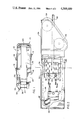
- FIG. 3 is an enlarged elevation view of the device shown in FIG. 2.
- FIG. 4 is a sectional view of the device which is shown in FIG. 3 along the lines II--II.
- FIG. 5 is a cross section of the pressure relief valve shown in FIG. 3 along lines III--III.
- FIG. 6 is a sectional view of the pressure control valve shown in FIG. 3.
- Compartment 18 includes a material receiving end portion 20 and a material discharge end portion 22. Extending along the bottom of the compartment 18 is a conventional endless flight conveyor (not shown).
- Discharge end portion 22 includes a tiltable end frame 26 which is tiltable to effect variation in the discharge height of the conveyor.
- an operator control station 28 Arranged on one side of the discharge end portion 22 is an operator control station 28.
- a cable reel assembly 30 Arranged on the opposite side of the discharge end portion 22 is a cable reel assembly 30 which includes the control device of the present invention.
- a power conductor or cable 32 is wound on the cable reel assembly 30.
- the tiltable end frame 26 carries suitable guides 34 for the cable 32, whereby the latter can be extended in various directions from the vehicle in connection with a suitable power source.
- forward and rearward shall refer respectively to ends 22 and 20 in the mine vehicle 10.
- Cable reel assembly 30 comprises an elongated generally cylindrical cable reel 38 which is supported by a stationary bracket 56.
- the cable reel 38 includes an elongated generally cylindrical drum member 42 which is coaxial and extends along the axis X--X of reel 38 which has left and right flanges 44 and 43 which are secured to drum 42 at the respective axial ends thereof.
- a cable receiving opening 50 extends transversly through the drum assembly intermediate the axial ends thereof for receiving end portion 52 of cable 32 within the interior of the drum.
- the cable end 52 maybe connected in any well known manner to the electrical system of the mine shuttle car.
- the preferred cable reel 38 is rotatably supported adjacent one axial end by bracket 56. With the cable reel assembly 30 so disposed, the cable reel 38 is rotatably driven during winding in cable by means of a suitable hydraulic motor 60 which is fixably secured to the vehicle body and which receives hydraulic pressure fluid from any suitable source such as a pump (not shown).
- a sprocket 62 is secured to the cable reel 38 adjacent bracket 56 and extends radially outward therefrom.
- Motor 60 rotatably drives reel 38 by means of a chain 66 which communicates between drive sprocket 63 on the outward drive shaft therefor and sprocket 62.
- the cable reel During unwinding of the cable 32 from the cable reel assembly 30 as when the mine vehicle 10 moves away from the power source (not shown) the cable reel would tend to freewheel about its rotating axis were it not for the pressure within the hydraulic system.
- the hydraulic motor 60 As the cable reel turns, because of the motion of the vehicle and resultant force of the cable being pulled off the reel, it drives the hydraulic motor 60 which is now acting as a pump to force hydraulic fluid through the cable reel control valve 61 as shown in FIGS. 3 and 4 and as described in greater detail herein below, to create a braking effect on the cable reel thereby preventing the reel from free spooling and dumping too much cable onto the ground when the vehicle slows or stops.
- the sprocket 62 during unwinding, would be the drive sprocket and would drive sprocket 63 by means of chain 66.
- FIGS. 2, 3, and 4 there is disclosed a device, generally denoted as 40, for sensing the amount of cable on the reel and varying the pressure to the hydraulic motor input during winding in or varying the back pressure in the motor 60 during unwinding.
- the changing pressure changes the drive torque or reel braking torque imparted through chain 66 to sprocket 62 or 63 of the cable reel assembly 30.
- the sensing device 40 consists of a roller 100 rotatably supported by brackets or lever arms 102 and 104.
- the brackets 102 and 104 are supported by bar or shaft 106 for rotation about axis Y--Y.
- Axis Y--Y is parallel to the axis X--X through the cable reel drum 42.
- two linkages generally denoted as 108 are connected to bar or shaft 106 by the pin connections 110 and 112 respectively.
- links 114 and 116 are rotatably connected to pins 110 and 112 respectively.
- the pins 110 and 112 join the ends 118 and 120 of links 114 and 116 to flange portions 122 and 124 which are connected to bar or shaft 106 for rotation therewith about axis Y--Y.
- Ends 126 and 128 of links 114 and 116 respectively are connected through a pin connection 130 and 132 to second links 134 and 136 of the link arrangement 108.
- the lengths of links 114, 116, 134 and 136 can be adjusted. In the preferred embodiment this is accomplished by threadedly coupling the ends such as 120 and 128 so that they may be adjusted towards or away from one another by the threaded interconnection therebetween.
- the links 134 and 136 have threaded rods 138 and 140 threaded into the ends thereof opposite the pin connection points 130 and 132.
- control valve 61 has an inlet 200 and an outlet 202. There is a movable control spool 204 located within a bore 206 between outlet 202 and inlet 200.
- spool 204 Internally of spool 204 there is a check valve 208.
- the spool 204 When the car is operating in a high torque mode, that is when the motor 60 is driving the cable reel 42, the spool 204 is positioned such that hydraulic fluid flows in the inlet 200 of valve 61 unseating check valve 208 and out the outlet 202 to the hydraulic motor 60.
- the spool 204 of the cable reel control valve 61 is moved by the hydraulic pressure developed by the hydraulic motor 60 now acting as a pump and moves such that the flow is from the inlet 200 to port 210 and then into a tank or reservoir where the hydraulic driving pump (not shown) recirculates it through the inlet 200.
- the flow from the hydraulic motor 60 is preventing from going directly to outlet 210 by check valve 208. Instead the flow of fluid from the reservoir through motor 60 back to the reservoir through port 210 is controlled by the low torque relief valve 142. Upon sufficient pressure to unseat the low torque relief valve 142, hydraulic fluid will flow will flow through outlet 202 from the hydraulic motor 60 through the relief valve 142 and to the reservoir through outlet 210. Similarly, during the driving portion of the cycle, fluid flows in through inlet 200 and to the outlet 202 as long as the pressure does not unseat relief valve 144 which again would permit flow from the inlet 200 directly to the reservoir thereby limiting the pressure to hydraulic motor 60 and therefore the output torque of that motor to the cable reel.
- the reel valve 61 basically allows flow in one direction from a hydraulic pump past the high torque relief valve 144 when the cable is being wound on the drum then to the hydraulic motor 60 to drive the cable reel.
- the control valve then allows fluid to flow in the opposite direction from the hydraulic motor 60, through the low torque relief valve 142 and then to a reservior (not shown) when the cable is being unwound from the cable reel and the cable reel is actually driving the hydraulic motor 60 making the motor 60 a pump.
- the low torque relief valve 142 acts to brake the cable reel and prevent it from free spooling.
- the amount of braking torque developed by the low torque relief valve depends upon the relief pressure setting, which can be varied as will be described below.
- the rods 138 and 140 will be moved by the linkage arrangement upon movement of the roller 100 in response to the amount of cable on the cable reel drum 42.
- the rods 138, 140 are coaxial with the axis of relief valves 142 and 144.
- Rods 138 and 140 move axially into the valves as the lever arm moves away from the surface of drum 42 and axially out of relief valves 142, 144 as the roller moves toward the surface of drum 42 as when cable is wound off the drum.
- FIG. 5 shows an internal cutaway of the cable relief valves 142 and 144 which in the preferred embodiment are of identical construction with the exception of the amount of built in tension on spring 148.
- the preferred relief valve has an inlet 150 from pressure control valve 62 and an outlet 152 which flows into a hydraulic reservoir tank (not shown). Fluid from either the hydraulic pump in the case of the high torque relief valve or from the hydraulic motor 60 as it is driven by the cable reel during unwinding enters the inlet 150 from the control valve 61 and through a hole 154 in the valve cartridge 156 the high pressure fluid impinges on rim 158 of poppet 60. The pressure from the fluid flowing through inlet 150 is balanced by the tension in spring 148.
- the relief settings of the low torque relief valve 142 and the high torque relief valve 144 are significantly different.
- the release setting for the low torque relief valve is between 150 and 300 psi and the setting for the high torque relief valve is between 350 and 850 psi.
- the different relief settings are accomplished with the use of identical springs 148 by including in the high torque relief valve a series of shims 168 and also by varying the initial distance which rod 140 is located within the housing 170 of relief valve 144.
- rods 138 and 140 extend only a predetermined distance within the housing 170 of the relief valve. This permits movement along the axis of housing 170 by rods 138 or 140 to compress spring 148.
- rods 138 and 140 can be moved out of the relief valve housing 170 a predetermined distance limited by stop 172. This movement either compressing the spring 148 or relieving the compression of spring 148 changes the relief valve setting by changing the pressure at which poppet 160 will unseat from seat 162.
- the preferred linkage arrangement provides the axial movement of rods 138 and 140 as discussed above.
- the valve 61 is mounted on the body 174 of the vahicle 10.
- the bar or shaft 106 which supports arms 102 and 104 is rotatably mounted on brackets attached to the body 174.
- bar or shaft 106 is mounted by brackets 176 and 178 which are bolted to body 174 by bolts 180 and 182.
- the brackets 122 and 124 are mounted on bar or shaft 106 for movement therewith as bar or shaft 106 rotates in response to the movement of roller 100.
- brackets 122 and 124 are adjustable with respect to axis Y--Y either towards or away from roller 100.
- the initial tension of spring 148 on either valve can be adjusted by moving the location of pin connection 110 and 112 by adjusting screws 186 and/or 187. For instance, if the location of pin connection 110 were moved upward toward roller 100, the initial insertion of rod 138 into relief valve 142 would be greater. With this method, one skilled in the art could adjust the relief settings at adjustment screws 186 and 187 without having to make any changes in the internals of valves 142 and 144.
- roller 100 movement of the roller 100 away from the surface of drum 142 would move the linkage system in a manner which would push rods 138 and 140 into valves 142 and 144 thereby compressing springs 148 and raising the relief pressure of either valve. This would produce either a higher braking torque if the control valve 61 is in the low torque mode or a higher drive torque if the control valve is in the high torque mode thereby producing a more constant tension in the cable 32.
- roller 100 Conversely as cable is wound off the drum, roller 100 would move towards the surface of cable reel drum 42 thereby moving rods 138 and 140 out of relief valves 142 and 144 thereby lowering the relief pressure and consequently reducing either the braking torque or the drive torque affecting the cable reel.
- the device of the present invention could still be used if the relief valves 142 and 144 were replaced by electric circuits capable of varying the current to the cable reel drive motor.
- the current to the drive motor would be varied in direct response to the amount of cable on the cable reel to thereby vary the drive torque to the motor.
- a regenerative braking circuit for a DC drive motor can be used to varying braking torque. Such a regernerative braking circuit is discussed in U.S. Pat. No. 4,042,864.
Abstract
Description
Claims (19)
Priority Applications (4)
| Application Number | Priority Date | Filing Date | Title |
|---|---|---|---|
| US06/604,600 US4569489A (en) | 1984-04-27 | 1984-04-27 | Cable tension control device |
| ZA848602A ZA848602B (en) | 1984-04-27 | 1984-11-02 | Cable tension control device |
| GB08428650A GB2158031B (en) | 1984-04-27 | 1984-11-13 | Cable tension control device |
| AU38524/85A AU574759B2 (en) | 1984-04-27 | 1985-02-07 | Cable tension control device |
Applications Claiming Priority (1)
| Application Number | Priority Date | Filing Date | Title |
|---|---|---|---|
| US06/604,600 US4569489A (en) | 1984-04-27 | 1984-04-27 | Cable tension control device |
Publications (1)
| Publication Number | Publication Date |
|---|---|
| US4569489A true US4569489A (en) | 1986-02-11 |
Family
ID=24420278
Family Applications (1)
| Application Number | Title | Priority Date | Filing Date |
|---|---|---|---|
| US06/604,600 Expired - Lifetime US4569489A (en) | 1984-04-27 | 1984-04-27 | Cable tension control device |
Country Status (4)
| Country | Link |
|---|---|
| US (1) | US4569489A (en) |
| AU (1) | AU574759B2 (en) |
| GB (1) | GB2158031B (en) |
| ZA (1) | ZA848602B (en) |
Cited By (25)
| Publication number | Priority date | Publication date | Assignee | Title |
|---|---|---|---|---|
| US4700023A (en) * | 1985-01-31 | 1987-10-13 | Metallgesellschaft Ag | Trackless, center articulation underground vehicle driven by an electric motor |
| US4982057A (en) * | 1989-09-11 | 1991-01-01 | Pyro Mining Company | Batwing for a shuttle car |
| US5551545A (en) * | 1994-03-18 | 1996-09-03 | Gelfman; Stanley | Automatic deployment and retrieval tethering system |
| WO1997028592A1 (en) * | 1996-02-02 | 1997-08-07 | Tamrock Oy | Method and arrangement for controlling cable winding and unwinding in an electrically driven vehicle |
| US5887815A (en) * | 1997-11-03 | 1999-03-30 | Pierce; Steve | Cable winding device for electrically powered mining vehicles |
| US6530537B2 (en) * | 2001-02-07 | 2003-03-11 | Joy Mm Delaware, Inc. | Movable electric machinery having a trailing cable extending through a hinged sheave bracket assembly |
| US20040094372A1 (en) * | 2002-07-31 | 2004-05-20 | Ventra Group Inc. | Brake actuation assembly for a vehicle |
| US6755284B2 (en) | 2001-05-24 | 2004-06-29 | Ventra Group Inc. | Electrically driven parking brake actuation assembly |
| US20040129508A1 (en) * | 2002-08-28 | 2004-07-08 | Ventra Group Inc. | Cable tension sensing device |
| US20060071116A1 (en) * | 2004-09-27 | 2006-04-06 | Quenneville Steven R | Cable dispensing and retrieval |
| KR100930526B1 (en) * | 2009-08-07 | 2009-12-09 | 주식회사 진화기술공사 | A device for maintaining tension of line in a transmission tower |
| US20100300826A1 (en) * | 2009-05-29 | 2010-12-02 | Joy Mm Delaware | Non-conductive trailing cable guide |
| US20110006149A1 (en) * | 2009-07-07 | 2011-01-13 | Benton Frederick Baugh | Method for automatic cable tension on a reel |
| JP2011073811A (en) * | 2009-09-29 | 2011-04-14 | Shinmaywa Industries Ltd | Hose reel device of washing device, and high-pressure washing vehicle with the same |
| US20110089284A1 (en) * | 2009-09-18 | 2011-04-21 | Dean Bartolone | Cable tensioning device |
| WO2011106954A1 (en) * | 2010-03-04 | 2011-09-09 | 湖南三一智能控制设备有限公司 | Shuttle car |
| CN102765639A (en) * | 2012-07-19 | 2012-11-07 | 沧州华海风电设备科技技术开发有限公司 | Electric shovel cable collecting vehicle |
| CN102910490A (en) * | 2011-08-01 | 2013-02-06 | 乔伊·姆·特拉华公司 | Low friction sheave bracket |
| US20140166419A1 (en) * | 2012-12-14 | 2014-06-19 | Joy Mm Delaware, Inc. | Shuttle car spring-assisted swinging sheave bracket |
| US20150251769A1 (en) * | 2014-03-07 | 2015-09-10 | Eads Construcciones Aeronauticas S.A. | In-flight refueling method and system for contorlling motion of the hose and drogue |
| CN105060034A (en) * | 2015-07-24 | 2015-11-18 | 国家电网公司 | Cable pay-off device and equipment |
| CN107317230A (en) * | 2017-07-25 | 2017-11-03 | 南京弘邦高分子材料有限公司 | A kind of electric power cabinet with tray |
| US10744881B2 (en) * | 2015-09-11 | 2020-08-18 | Schunk Transit Systems Gmbh | Positioning unit for a charging station and method for making contact |
| CN113165532A (en) * | 2018-12-04 | 2021-07-23 | 山特维克矿山工程机械有限公司 | Arrangement and method in an underground mining machine |
| FR3138421A1 (en) | 2022-08-01 | 2024-02-02 | Elwedys | Motorized cable unwinder |
Families Citing this family (4)
| Publication number | Priority date | Publication date | Assignee | Title |
|---|---|---|---|---|
| GB2199304A (en) * | 1986-12-24 | 1988-07-06 | Li Wen Guang | Rewindable hose reel |
| GB8729481D0 (en) * | 1987-12-17 | 1988-02-03 | British Nuclear Fuels Plc | Pumps & pump handling apparatus |
| FR2734313B1 (en) * | 1995-05-17 | 1997-08-08 | Lucet Raymond | DEVICE FOR THE ELECTRICAL SUPPLY OF A SUBMERSIBLE PUMP SUSPENDED FROM A PIPE, IN PARTICULAR A FLEXIBLE PIPE |
| CN112061893B (en) * | 2020-08-04 | 2022-09-09 | 北京国电富通科技发展有限责任公司 | Water pipe and cable synchronous winding and unwinding machine control system and method based on frequency converter |
Citations (7)
| Publication number | Priority date | Publication date | Assignee | Title |
|---|---|---|---|---|
| US23300A (en) * | 1859-03-22 | harmon | ||
| US24178A (en) * | 1859-05-24 | Apparatus for cooking by steam | ||
| US2090707A (en) * | 1932-06-06 | 1937-08-24 | Goodman Mfg Co | Mine locomotive |
| US2665081A (en) * | 1950-03-18 | 1954-01-05 | Goodman Mfg Co | Cable reel |
| US3334839A (en) * | 1965-10-22 | 1967-08-08 | Westinghouse Air Brake Co | Cable reel tension system |
| US3460776A (en) * | 1967-12-07 | 1969-08-12 | Du Pont | Film winding apparatus |
| US3934837A (en) * | 1974-10-04 | 1976-01-27 | Keiltex Corporation | Web winder and compensator apparatus |
Family Cites Families (1)
| Publication number | Priority date | Publication date | Assignee | Title |
|---|---|---|---|---|
| DE2822129C2 (en) * | 1978-05-20 | 1983-03-31 | Gebr. Eickhoff, Maschinenfabrik U. Eisengiesserei Mbh, 4630 Bochum | Method and device for regulating the tensile force of a reel which is connected to the cable trolley of a mining machine via a tensile element |
-
1984
- 1984-04-27 US US06/604,600 patent/US4569489A/en not_active Expired - Lifetime
- 1984-11-02 ZA ZA848602A patent/ZA848602B/en unknown
- 1984-11-13 GB GB08428650A patent/GB2158031B/en not_active Expired
-
1985
- 1985-02-07 AU AU38524/85A patent/AU574759B2/en not_active Ceased
Patent Citations (7)
| Publication number | Priority date | Publication date | Assignee | Title |
|---|---|---|---|---|
| US23300A (en) * | 1859-03-22 | harmon | ||
| US24178A (en) * | 1859-05-24 | Apparatus for cooking by steam | ||
| US2090707A (en) * | 1932-06-06 | 1937-08-24 | Goodman Mfg Co | Mine locomotive |
| US2665081A (en) * | 1950-03-18 | 1954-01-05 | Goodman Mfg Co | Cable reel |
| US3334839A (en) * | 1965-10-22 | 1967-08-08 | Westinghouse Air Brake Co | Cable reel tension system |
| US3460776A (en) * | 1967-12-07 | 1969-08-12 | Du Pont | Film winding apparatus |
| US3934837A (en) * | 1974-10-04 | 1976-01-27 | Keiltex Corporation | Web winder and compensator apparatus |
Cited By (33)
| Publication number | Priority date | Publication date | Assignee | Title |
|---|---|---|---|---|
| US4700023A (en) * | 1985-01-31 | 1987-10-13 | Metallgesellschaft Ag | Trackless, center articulation underground vehicle driven by an electric motor |
| US4982057A (en) * | 1989-09-11 | 1991-01-01 | Pyro Mining Company | Batwing for a shuttle car |
| US5551545A (en) * | 1994-03-18 | 1996-09-03 | Gelfman; Stanley | Automatic deployment and retrieval tethering system |
| WO1997028592A1 (en) * | 1996-02-02 | 1997-08-07 | Tamrock Oy | Method and arrangement for controlling cable winding and unwinding in an electrically driven vehicle |
| US6119837A (en) * | 1996-02-02 | 2000-09-19 | Tamrock Oy | Method and arrangement for controlling cable winding and unwinding in an electrically driven vehicle |
| US5887815A (en) * | 1997-11-03 | 1999-03-30 | Pierce; Steve | Cable winding device for electrically powered mining vehicles |
| US6530537B2 (en) * | 2001-02-07 | 2003-03-11 | Joy Mm Delaware, Inc. | Movable electric machinery having a trailing cable extending through a hinged sheave bracket assembly |
| US6755284B2 (en) | 2001-05-24 | 2004-06-29 | Ventra Group Inc. | Electrically driven parking brake actuation assembly |
| US6848545B2 (en) | 2002-07-31 | 2005-02-01 | Ventra Group Inc. | Brake actuation assembly for a vehicle |
| US20040094372A1 (en) * | 2002-07-31 | 2004-05-20 | Ventra Group Inc. | Brake actuation assembly for a vehicle |
| US20040129508A1 (en) * | 2002-08-28 | 2004-07-08 | Ventra Group Inc. | Cable tension sensing device |
| US7011188B2 (en) | 2002-08-28 | 2006-03-14 | Ventra Group Inc. | Cable tension sensing device |
| US20060071116A1 (en) * | 2004-09-27 | 2006-04-06 | Quenneville Steven R | Cable dispensing and retrieval |
| US20100300826A1 (en) * | 2009-05-29 | 2010-12-02 | Joy Mm Delaware | Non-conductive trailing cable guide |
| US20110006149A1 (en) * | 2009-07-07 | 2011-01-13 | Benton Frederick Baugh | Method for automatic cable tension on a reel |
| KR100930526B1 (en) * | 2009-08-07 | 2009-12-09 | 주식회사 진화기술공사 | A device for maintaining tension of line in a transmission tower |
| US20110089284A1 (en) * | 2009-09-18 | 2011-04-21 | Dean Bartolone | Cable tensioning device |
| JP2011073811A (en) * | 2009-09-29 | 2011-04-14 | Shinmaywa Industries Ltd | Hose reel device of washing device, and high-pressure washing vehicle with the same |
| WO2011106954A1 (en) * | 2010-03-04 | 2011-09-09 | 湖南三一智能控制设备有限公司 | Shuttle car |
| CN102910490A (en) * | 2011-08-01 | 2013-02-06 | 乔伊·姆·特拉华公司 | Low friction sheave bracket |
| US20130228386A1 (en) * | 2011-08-01 | 2013-09-05 | Joy Mm Delaware, Inc. | Low friction sheave bracket |
| US8985289B2 (en) * | 2011-08-01 | 2015-03-24 | Joy Mm Delaware, Inc. | Low friction sheave bracket |
| CN102910490B (en) * | 2011-08-01 | 2019-01-11 | 久益环球地下采矿有限责任公司 | Low friction pulley bracket |
| CN102765639B (en) * | 2012-07-19 | 2016-04-13 | 沧州华海风电设备科技技术开发有限公司 | A kind of power shovel collection cable car |
| CN102765639A (en) * | 2012-07-19 | 2012-11-07 | 沧州华海风电设备科技技术开发有限公司 | Electric shovel cable collecting vehicle |
| US20140166419A1 (en) * | 2012-12-14 | 2014-06-19 | Joy Mm Delaware, Inc. | Shuttle car spring-assisted swinging sheave bracket |
| US20150251769A1 (en) * | 2014-03-07 | 2015-09-10 | Eads Construcciones Aeronauticas S.A. | In-flight refueling method and system for contorlling motion of the hose and drogue |
| US9969502B2 (en) * | 2014-03-07 | 2018-05-15 | Eads Construcciones Aeronauticas S.A. | In-flight refueling method and system for controlling motion of the hose and drogue |
| CN105060034A (en) * | 2015-07-24 | 2015-11-18 | 国家电网公司 | Cable pay-off device and equipment |
| US10744881B2 (en) * | 2015-09-11 | 2020-08-18 | Schunk Transit Systems Gmbh | Positioning unit for a charging station and method for making contact |
| CN107317230A (en) * | 2017-07-25 | 2017-11-03 | 南京弘邦高分子材料有限公司 | A kind of electric power cabinet with tray |
| CN113165532A (en) * | 2018-12-04 | 2021-07-23 | 山特维克矿山工程机械有限公司 | Arrangement and method in an underground mining machine |
| FR3138421A1 (en) | 2022-08-01 | 2024-02-02 | Elwedys | Motorized cable unwinder |
Also Published As
| Publication number | Publication date |
|---|---|
| AU3852485A (en) | 1985-10-31 |
| AU574759B2 (en) | 1988-07-14 |
| GB2158031B (en) | 1987-08-26 |
| ZA848602B (en) | 1985-06-26 |
| GB8428650D0 (en) | 1984-12-19 |
| GB2158031A (en) | 1985-11-06 |
Similar Documents
| Publication | Publication Date | Title |
|---|---|---|
| US4569489A (en) | Cable tension control device | |
| EP0008352B1 (en) | Winding system for flexible conduits and cables | |
| EP1651552B1 (en) | Levelwind system for coiled tubing reel | |
| CA2441650C (en) | Level wind apparatus for use on a snow grooming vehicle | |
| US2395302A (en) | Cable reel | |
| US3371799A (en) | Telescopic boom angle control system | |
| CA2246059C (en) | Method and arrangement for controlling cable winding and unwinding in an electrically driven vehicle | |
| US3941324A (en) | Cable stringing apparatus | |
| US4318533A (en) | Apparatus for maintaining tension on a tension cable | |
| SE460690B (en) | DEVICE FOR WINDING UP CABLES FOR ELECTRICALLY DRIVED VEHICLES OR WORKING MACHINES | |
| EP0088868A1 (en) | Underground railless vehicle | |
| CN110030217B (en) | Control system of floating oil cylinder of chassis of overhead working truck and overhead working truck | |
| US2467238A (en) | Fluid pressure cable reel drive | |
| US4266724A (en) | Mobile spraying apparatus with an axial pipe-carrier drum | |
| US2507297A (en) | Tension equalizing apparatus | |
| US4419042A (en) | Cotton module transport processes | |
| US2665081A (en) | Cable reel | |
| US4029358A (en) | Rear dump operating mechanism | |
| US2639103A (en) | Vehicle reel control | |
| US3556484A (en) | Aerial tramway power and control means | |
| US2669366A (en) | Unloading mechanism for motor vehicles | |
| US3250492A (en) | Automatic regulator for cable reel | |
| US3158356A (en) | Automatic regulator for cable reel | |
| US2707598A (en) | Cable reel control for self-propelled vehicles | |
| US3045974A (en) | Reversible power-driven winch with automatic control of reverse speed |
Legal Events
| Date | Code | Title | Description |
|---|---|---|---|
| AS | Assignment |
Owner name: JOY MANUFACTURING COMPANY, 301 GRANT ST., PITTSBUR Free format text: ASSIGNMENT OF ASSIGNORS INTEREST.;ASSIGNORS:FREY, GEORGE R.;DICKEY, RONALD K.;BLEAKLEY, DARYL A.;AND OTHERS;REEL/FRAME:004324/0493 Effective date: 19840427 |
|
| STCF | Information on status: patent grant |
Free format text: PATENTED CASE |
|
| AS | Assignment |
Owner name: JOY TECHNOLOGIES INC., 301 GRANT STREET, PITTSBURG Free format text: ASSIGNMENT OF ASSIGNORS INTEREST.;ASSIGNOR:JOY MANUFACTURING COMPANY, A CORP. OF PA;REEL/FRAME:004880/0430 Effective date: 19870529 Owner name: JOY TECHNOLOGIES INC., A CORP. OF DE.,PENNSYLVANIA Free format text: ASSIGNMENT OF ASSIGNORS INTEREST;ASSIGNOR:JOY MANUFACTURING COMPANY, A CORP. OF PA;REEL/FRAME:004880/0430 Effective date: 19870529 |
|
| AS | Assignment |
Owner name: JOY TECHNOLOGIES INC., 301 GRANT STREET, PITTSBURG Free format text: ASSIGNMENT OF ASSIGNORS INTEREST.;ASSIGNOR:JOY MANUFACTURING COMPANY, A CORP. OF PA;REEL/FRAME:004747/0261 Effective date: 19870626 Owner name: CITIBANK, N.A., 641 LEXINGTON AVENUE, NEW YORK, NE Free format text: ASSIGNMENT OF ASSIGNORS INTEREST.;ASSIGNOR:JOY TECHNOLOGIES INC., 301 GRANT STREET, PITTSBURGH, PA 15219, A DE CORP.;REEL/FRAME:004846/0025 Effective date: 19870626 Owner name: CITIBANK, N.A.,NEW YORK Free format text: ASSIGNMENT OF ASSIGNORS INTEREST;ASSIGNOR:JOY TECHNOLOGIES INC., 301 GRANT STREET, PITTSBURGH, PA 15219, A DE CORP.;REEL/FRAME:004846/0025 Effective date: 19870626 Owner name: JOY TECHNOLOGIES INC., PENNSYLVANIA Free format text: ASSIGNMENT OF ASSIGNORS INTEREST;ASSIGNOR:JOY MANUFACTURING COMPANY, A CORP. OF PA;REEL/FRAME:004747/0261 Effective date: 19870626 |
|
| AS | Assignment |
Owner name: JOY MANUFACTURING COMPANY Free format text: ASSIGNMENT OF ASSIGNORS INTEREST. EFFECTIVE DATE;ASSIGNOR:JOY TECHNOLOGIES INCL., (A DE CORP.);REEL/FRAME:004827/0367 Effective date: 19870626 Owner name: JOY MANUFACTURING COMPANY,STATELESS Free format text: ASSIGNMENT OF ASSIGNORS INTEREST;ASSIGNOR:JOY TECHNOLOGIES INCL., (A DE CORP.);REEL/FRAME:004827/0367 Effective date: 19870626 |
|
| AS | Assignment |
Owner name: CITIBANK, N.A., 641 LEXINGTON AVENUE, NEW YORK, NE Free format text: SECURITY INTEREST;ASSIGNOR:JOY TECHNOLOGIES INC.,;REEL/FRAME:004936/0730 Effective date: 19870626 |
|
| FEPP | Fee payment procedure |
Free format text: PAYOR NUMBER ASSIGNED (ORIGINAL EVENT CODE: ASPN); ENTITY STATUS OF PATENT OWNER: LARGE ENTITY |
|
| FPAY | Fee payment |
Year of fee payment: 4 |
|
| AS | Assignment |
Owner name: JOY TECHNOLOGIES INC., A CORP OF DE, PENNSYLVANIA Free format text: RELEASED BY SECURED PARTY;ASSIGNORS:MC CARTNEY, DEREK L.;ARCHIBALD, JOHN H.;REEL/FRAME:005237/0152 Effective date: 19870626 |
|
| AS | Assignment |
Owner name: JOY TECHNOLOGIES, INC., A CORP OF DE Free format text: RELEASED BY SECURED PARTY;ASSIGNOR:CITIBANK N.A.;REEL/FRAME:005237/0187 Effective date: 19891011 |
|
| AS | Assignment |
Owner name: CONNECTICUT NATIONAL BANK, THE, CONNECTICUT Free format text: SECURITY INTEREST;ASSIGNOR:JOY TECHNOLOGIES INC., A DE CORP.;REEL/FRAME:005173/0843 Effective date: 19891012 |
|
| AS | Assignment |
Owner name: CONNECTICUT NATIONAL BANK, THE, CONNECTICUT Free format text: SECURITY INTEREST;ASSIGNOR:JOY TECHNOLOGIES INC., A CORPORATION OF DE;REEL/FRAME:005957/0475 Effective date: 19911210 |
|
| AS | Assignment |
Owner name: CONNECTICUT NATIONAL BANK, N.A., THE, CONNECTICUT Free format text: SECURITY INTEREST;ASSIGNOR:JOY MM DELAWARE, INC., A CORP. OF DE;REEL/FRAME:006142/0639 Effective date: 19920229 |
|
| AS | Assignment |
Owner name: JOY MM DELAWARE, INC., DELAWARE Free format text: ASSIGNMENT OF ASSIGNORS INTEREST.;ASSIGNOR:JOY TECHNOLOGIES INC.;REEL/FRAME:006329/0580 Effective date: 19920229 |
|
| FPAY | Fee payment |
Year of fee payment: 8 |
|
| FEPP | Fee payment procedure |
Free format text: PAYOR NUMBER ASSIGNED (ORIGINAL EVENT CODE: ASPN); ENTITY STATUS OF PATENT OWNER: LARGE ENTITY Free format text: PAYER NUMBER DE-ASSIGNED (ORIGINAL EVENT CODE: RMPN); ENTITY STATUS OF PATENT OWNER: LARGE ENTITY |
|
| FPAY | Fee payment |
Year of fee payment: 12 |