EP0006307B1 - Boiler - Google Patents
Boiler Download PDFInfo
- Publication number
- EP0006307B1 EP0006307B1 EP79300932A EP79300932A EP0006307B1 EP 0006307 B1 EP0006307 B1 EP 0006307B1 EP 79300932 A EP79300932 A EP 79300932A EP 79300932 A EP79300932 A EP 79300932A EP 0006307 B1 EP0006307 B1 EP 0006307B1
- Authority
- EP
- European Patent Office
- Prior art keywords
- bed
- boiler
- tubes
- fuel
- feeding
- Prior art date
- Legal status (The legal status is an assumption and is not a legal conclusion. Google has not performed a legal analysis and makes no representation as to the accuracy of the status listed.)
- Expired
Links
- 238000002485 combustion reaction Methods 0.000 claims abstract description 36
- 239000000463 material Substances 0.000 claims abstract description 27
- 230000000694 effects Effects 0.000 claims abstract description 6
- 239000000446 fuel Substances 0.000 claims description 37
- XLYOFNOQVPJJNP-UHFFFAOYSA-N water Substances O XLYOFNOQVPJJNP-UHFFFAOYSA-N 0.000 claims description 14
- 239000007789 gas Substances 0.000 claims description 13
- 239000011236 particulate material Substances 0.000 claims description 7
- 239000002915 spent fuel radioactive waste Substances 0.000 claims description 7
- 239000000567 combustion gas Substances 0.000 claims description 3
- 238000005243 fluidization Methods 0.000 claims description 2
- 239000008236 heating water Substances 0.000 claims 1
- 239000012530 fluid Substances 0.000 abstract description 5
- 239000002956 ash Substances 0.000 description 26
- VYPSYNLAJGMNEJ-UHFFFAOYSA-N Silicium dioxide Chemical compound O=[Si]=O VYPSYNLAJGMNEJ-UHFFFAOYSA-N 0.000 description 9
- 238000005192 partition Methods 0.000 description 8
- VTYYLEPIZMXCLO-UHFFFAOYSA-L Calcium carbonate Chemical compound [Ca+2].[O-]C([O-])=O VTYYLEPIZMXCLO-UHFFFAOYSA-L 0.000 description 6
- 229910000019 calcium carbonate Inorganic materials 0.000 description 3
- 239000003245 coal Substances 0.000 description 3
- 239000003546 flue gas Substances 0.000 description 3
- 239000004576 sand Substances 0.000 description 3
- 239000000377 silicon dioxide Substances 0.000 description 3
- 239000004449 solid propellant Substances 0.000 description 3
- NINIDFKCEFEMDL-UHFFFAOYSA-N Sulfur Chemical compound [S] NINIDFKCEFEMDL-UHFFFAOYSA-N 0.000 description 2
- 239000005864 Sulphur Substances 0.000 description 2
- OSGAYBCDTDRGGQ-UHFFFAOYSA-L calcium sulfate Chemical compound [Ca+2].[O-]S([O-])(=O)=O OSGAYBCDTDRGGQ-UHFFFAOYSA-L 0.000 description 2
- 238000000605 extraction Methods 0.000 description 2
- 230000005484 gravity Effects 0.000 description 2
- 239000000203 mixture Substances 0.000 description 2
- 239000002245 particle Substances 0.000 description 2
- 230000000903 blocking effect Effects 0.000 description 1
- 239000001175 calcium sulphate Substances 0.000 description 1
- 235000011132 calcium sulphate Nutrition 0.000 description 1
- 230000003197 catalytic effect Effects 0.000 description 1
- 238000001816 cooling Methods 0.000 description 1
- 239000000284 extract Substances 0.000 description 1
- 239000010881 fly ash Substances 0.000 description 1
- 239000007788 liquid Substances 0.000 description 1
- 239000007787 solid Substances 0.000 description 1
Images


Classifications
-
- B—PERFORMING OPERATIONS; TRANSPORTING
- B01—PHYSICAL OR CHEMICAL PROCESSES OR APPARATUS IN GENERAL
- B01J—CHEMICAL OR PHYSICAL PROCESSES, e.g. CATALYSIS OR COLLOID CHEMISTRY; THEIR RELEVANT APPARATUS
- B01J8/00—Chemical or physical processes in general, conducted in the presence of fluids and solid particles; Apparatus for such processes
- B01J8/18—Chemical or physical processes in general, conducted in the presence of fluids and solid particles; Apparatus for such processes with fluidised particles
- B01J8/24—Chemical or physical processes in general, conducted in the presence of fluids and solid particles; Apparatus for such processes with fluidised particles according to "fluidised-bed" technique
- B01J8/36—Chemical or physical processes in general, conducted in the presence of fluids and solid particles; Apparatus for such processes with fluidised particles according to "fluidised-bed" technique with fluidised bed through which there is an essentially horizontal flow of particles
-
- F—MECHANICAL ENGINEERING; LIGHTING; HEATING; WEAPONS; BLASTING
- F22—STEAM GENERATION
- F22B—METHODS OF STEAM GENERATION; STEAM BOILERS
- F22B31/00—Modifications of boiler construction, or of tube systems, dependent on installation of combustion apparatus; Arrangements or dispositions of combustion apparatus
- F22B31/0007—Modifications of boiler construction, or of tube systems, dependent on installation of combustion apparatus; Arrangements or dispositions of combustion apparatus with combustion in a fluidized bed
- F22B31/0046—Modifications of boiler construction, or of tube systems, dependent on installation of combustion apparatus; Arrangements or dispositions of combustion apparatus with combustion in a fluidized bed for boilers of the shell type, e.g. with furnace box
- F22B31/0053—Modifications of boiler construction, or of tube systems, dependent on installation of combustion apparatus; Arrangements or dispositions of combustion apparatus with combustion in a fluidized bed for boilers of the shell type, e.g. with furnace box with auxiliary water tubes
-
- F—MECHANICAL ENGINEERING; LIGHTING; HEATING; WEAPONS; BLASTING
- F23—COMBUSTION APPARATUS; COMBUSTION PROCESSES
- F23C—METHODS OR APPARATUS FOR COMBUSTION USING FLUID FUEL OR SOLID FUEL SUSPENDED IN A CARRIER GAS OR AIR
- F23C10/00—Fluidised bed combustion apparatus
- F23C10/02—Fluidised bed combustion apparatus with means specially adapted for achieving or promoting a circulating movement of particles within the bed or for a recirculation of particles entrained from the bed
Definitions
- This invention relates to boilers.
- Solid fuel boilers require stoking of the fuel in order to achieve efficient combustion thereof.
- Automatic mechanical stoking has proved more efficient than manual stoking, due to better control of fuel/air ratios.
- the use of a fluidised bed has led to a further improvement in that the amount of excess air required for efficient combustion is much lower than with automatic mechanical stoking.
- Boilers utilising a conventional fluidised bed are such that a substantially vertical turbulent motion is produced within the bed, due to the flow of gases upwardly through the bed.
- the intimate mixing of fuel and air within the bed allows higher combustion rates per unit area of grate than could be achieved by mechanical stoking.
- a plurality of fuel inlets, or at least a single fuel inlet with a mechanical device for distributing or scattering the fuel over the surface of the bed is required in order to give a good distribution of fuel over the grate area and the feeding of the fuel through the various inlets has to be carefully balanced in order to give most efficient combustion by the bed as a whole.
- German Patent Specification No 2352412 discloses an incinerator including a combustion chamber in which the bed of particulate material is fluidised non-uniformly.
- British Patent Specification No 1461411 describes a boiler including a combustion chamber containing a bed of particulate material which is fluidised in a non-uniform manner.
- the circulation effected is a plane perpendicular to the longitudinal axis of the combustion chamber.
- the bed has an inclined base to help mix the bed.
- bed material is lost from the bed since the combustion gases expand upwards taking with them elutriated bed material.
- a boiler comprising a combustion chamber and means for circulating water about the exterior surface of said combustion chamber, means for feeding combustion gases from said combustion chamber through tubes located within said circulating water, the combustion chamber enclosing a bed for receiving particulate material, said bed having a base which is inclined upwardly from a first end to a second opposite end, means for feeding air to said bed to effect fluidisation of said material characterised in that said means effects circulation of said material by movement thereof from said first end to said second end in an upper region of the bed and from said second end to said first end in a lower region of the bed, and in that the boiler also includes deflection means located over bed material adjacent said first end to control the upward expansion of the bed adjacent said first end, means for feeding fuel to said bed at or near said first end.
- the tubes are arranged substantially horizontally above said bed.
- the arrangement may be a so-called single pass system in which the gas flow through the passages is in one direction only before leaving the boiler.
- the arrangement may be a so-called double pass system whereby gases flow in one direction through passages and are redirected through further passages before leaving the boiler.
- the heat exchange means further include means for feeding working fluid within a conduit through the bed itself, thereby both to cool the bed and also to receive heat therefrom.
- the working fluid exiting from said conduit is then fed therefrom to said plurality of passages.
- the bed is arranged within a chamber located within the boiler, the working fluid being, in use, passed through the space defined by the exterior of the chamber wall and the interior of the boiler wall and the bed material extending so as to contact the interior of the chamber wall over at least a portion thereof.
- the working fluid being, in use, passed through the space defined by the exterior of the chamber wall and the interior of the boiler wall and the bed material extending so as to contact the interior of the chamber wall over at least a portion thereof.
- the bed fluidising means include means for feeding air into the bed and the bed includes a spent fuel outlet, the arrangement being such that air may be pre-heated by spent fuel before the air is fed to the bed.
- the spent fuel may be ash, which contains a great deal of heat and this hot ash may be used to pre-heat the air, the pre-heated air then being mixed with the fuel so that it is used to pump the fuel on to the fluidised bed.
- the boiler includes a single fuel inlet to the bed.
- a single fuel inlet is necessary because the bed is fluidised in such a way that there is a circulation of the bed material thereby distributing the fuel throughout the bed.
- the air feeding means for the fluidised bed are arranged to feed air through the base of the bed.
- the base of the bed there may be arranged side by side plenum chambers, the amount of air fed to each plenum chamber and/or the size of each plenum chamber varying so that the amount of air injected into the bed is non-uniform in such a way as to cause the circulating mottion of the bed material within the bed.
- the conduit extends across that region of bed subjected to the greatest air flow. It is also preferred that a deflector or partition be located above the bed at the region of greatest air flow. It has been found that for a bed where the maximum air flow velocity in the bed is about 4.88 m/sec (16 ft/sec), the heat transfer was about 0.45 kW/(m 2 K) (80 BTU/hr/sq ft/°F) whereas the heat transfer in a comparable non-circulating fluidised bed boiler was only about 0.28 kW/(m 2 K) (50 BTU/hr/sq ft/°F).
- fuel combustion means adapted for fitting to a boiler, said fuel combustion means comprising a bed for receiving particulate material and means for fluidising material in the bed in a non-uniform manner to effect circulation of said material within the bed.
- Such fuel combustion means may be used to replace, for instance, an oil burner in an existing boiler.
- a boiler in accordance with the present invention may use any fuel and it is a particular advantage that the boiler may operate efficiently with fuel having a low calorific value, for instance, low grade coal or municipal refuse.
- the fuel may be solid, liquid or gaseous although only solid fuels give rise to a large amount of ash. Accordingly, it is a particular advantage that a boiler in accordance with the present invention can utilise fuels with high ash content. These are not normally burnt because the amount of heat lost in the ash is very high. Thus, such fuels have the same transportation costs as high grade fuels, but a large percentage of the potential heat output has hitherto been discarded with the ash.
- the particulate bed material may be inert, for instance, a silica sand or it may be reactive, for instance calcium carbonate which will react with sulphur in the fuel to form calcium sulphate, thereby reducing the emission of sulphur into the atmosphere.
- a boiler in accordancwe with the present invention includes a shell 1, within which is mounted a combustion chamber 3 which extends from one end wall 5 of the boiler substantially the whole of the length of the boiler, terminating in a flue back 7.
- the shell is provided with inlet 13 and outlet 15, whereby water may be circulated around tubes 11.
- a fluidised bed 17 Located within chamber 3 is a fluidised bed 17, the side walls of which are provided by the wall of chamber 3, bed 17 having a flat base 19 which slopes upwardly from end wall 5 of the boiler to rear wall 21 of the fluidised bed.
- plenum chambers 21, 23 and 25 Located below base 19 are plenum chambers 21, 23 and 25 which increase in size from end wall 5 to rear wall 21. Air is supplied to each of the plenum chambers by pump 27, the air being fed to positions within the plenum chambers along distribution tubes 29.
- Base 19 is perforated to allow air to pass into the bed from the plenum chambers.
- Bed 17 is filled with a suitable particulate material 30 such as silica sand or calcium carbonate up to a level just below the top of rear wall 21.
- a suitable particulate material 30 such as silica sand or calcium carbonate up to a level just below the top of rear wall 21.
- the bed 17 is provided with an outlet 31 to which outlet 31 is connected an ash extraction device 33 whereby ash may be extracted from the bed and passed to an ash and bed separator device 35. It will be noted that outlet 31 is at the lowest part of the bed where, under the influence of gravity and due to the circulation of the bed material, the ash tends to collect.
- fuel inlet 37 inclines downwardly through the end wall of the boiler and terminates within the boiler above the fluidised bed 17, opening into the space above the bed at an inclined partition member 39 which forms a deflector ensuring good circulation of bed material and restricting the depth of the bed material above the region of greatest air flow thereby assisting heat transfer in the bed.
- Partition member 39 is connected to return partition 41 and these partitions, together with the wall of the combustion chamber and rear partition 43, define an expansion space 45 which reduces the velocity of the flue gases produced by the combustion.
- each tube 47 being U-shaped, the arms of the tube 47 being arranged in a vertical plane and opening at the front wall of the fluidised bed 17.
- These tubes 47 enable water, passed through inlet 49, to extract heat from the bed, thereby to cool it, passing out through outlet 51.
- the boiler feed water may be preheated by connecting outlet 51 to boiler inlet 13, or by connecting outlet 15 to inlet 49 a degree of super heat may be achieved.
- the two water circuits may be separate.
- the tubes 47 extend at least across the bed above plenum chambers 21 and 23 where air flow is greatest, since it is in this region where heat transfer is most efficient.
- the bed 17 Since air is forced through base 19 into bed 17 by pump 27 via chambers 21, 23 and 25 at different velocities, the bed 17 is caused to expand to the extent allowed by partition member 39. At the same time the bed material circulates in the direction shown by arrow 30, the movement being guided by member 39 at the top left hand portion of the bed. As a result of this movement of the bed material, the fuel, even though entering the boiler through only a single inlet, is distributed throughout the bed thereby ensuring efficient combustion of the fuel even if finely divided. In addition, the defluidised ash collects at outlet 31 as mentioned above. Furthermore, the residence time of fuel in the bed is high compared with a fluidised bed in which no such circulating movement takes place, thus combustion is more complete.
- the flue gases released from the bed pass upwardly into expansion space 45 and then downwardly between partitions 43 and 53 and thence, into flue back 7 where they travel upwardly again before entering lower tubes 55 of the set of tubes 11.
- the gases pass along lower tubes 55 from the rear of the boiler at the front end and then return along the whole of the length of the boiler along upper tubes 57 of the series of tubes 11, exiting from the boiler through outlet 59 controlled by butterfly valve 61. During the passage of the gases through tubes 11, they exchange heat with water circulated around the tubes.
- a portion of the flue gases, carrying fine ash particles, is sucked through outlet 63 at the base of the boiler.
- This particle/gas mixture is fed to ash separator 65 where the fine ash is separated from the gas, the latter being then fed to outlet 59.
- another boiler in accordance with the present invention comprises a shell 101 within which is located a combustion chamber 103, the space between combustion chamber 103 and the wall of shell 101 being provided with tubes 105 around which water may be circulated.
- gases from the combustion chamber 103 pass into conduit 107 through ports 109 and thence to the front of boiler 101 where they enter tubes 105.
- the gases pass through tubes 105 from the front to the back of the boiler and enter outlet 111 controlled by butterfly valve 113.
- the gas makes only a single pass through the boiler although in another similar embodiment, the arrangement may be a double pass system as with the boiler described with reference to Figures 1 and 2.
- the boiler of Figures 3 and 4 is a wet back boiler, the water passing into space 115 at the back of the combustion chamber and also circulating under the combustion chamber within space 117.
- combustion chamber 103 there is a fluidised bed, the wall of which is provided entirely by the wall of chamber 103.
- particulate material 119 which may be inert material such as silica sand or catalytic material such as calcium carbonate.
- the boiler of Figures 3 and 4 may otherwise be similar to that of Figures 1 and 2. It may be provided with heat exchange tubes located within the bed, similar to tubes 47 of the embodiment of Figures 1 and 2, although these are not shown in Figures 3 and 4.
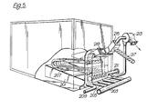
- FIG. 5 there is shown a combustion device for fitting to an existing boiler.
- the existing boiler may have previously been fitted with an oil burner but it may be desired to replace this with a solid fuel burner.
- the combustion device is broadly similar to that shown in the boiler of Figures 1 and 2 and includes an arrangement of plenum chambers 201 to which air may be fed by tubes 203 and 205.
- the bed material would be placed over the grates of the plenum chambers so as to surround water cooling tubes 207. Fly ash falling through the grate may be removed through outlet 209. Heavier ash collecting at the lower end of the bed may be extracted by means of ash extractor 211 and then mixed with air before being fed to separator device 213.
- Pre-heated air together with bed material which has been separated from the ash in device 213 is then fed to inlet 215. It is mixed at inlet 215 with fuel, which in this case is coal, fed to inlet via coal feed 217.
- the combustion system is provided with a start-up burner 219 and when the system is fitted to a boiler it operates in a manner similar to that described with reference to the boiler of Figures 1 and 2.
Landscapes
- Engineering & Computer Science (AREA)
- Chemical & Material Sciences (AREA)
- Combustion & Propulsion (AREA)
- General Engineering & Computer Science (AREA)
- Mechanical Engineering (AREA)
- Thermal Sciences (AREA)
- Physics & Mathematics (AREA)
- Chemical Kinetics & Catalysis (AREA)
- Organic Chemistry (AREA)
- Fluidized-Bed Combustion And Resonant Combustion (AREA)
- Solid-Fuel Combustion (AREA)
- Steam Or Hot-Water Central Heating Systems (AREA)
- Gasification And Melting Of Waste (AREA)
Abstract
Description
- This invention relates to boilers.
- Solid fuel boilers require stoking of the fuel in order to achieve efficient combustion thereof. Automatic mechanical stoking has proved more efficient than manual stoking, due to better control of fuel/air ratios. The use of a fluidised bed has led to a further improvement in that the amount of excess air required for efficient combustion is much lower than with automatic mechanical stoking.
- Boilers utilising a conventional fluidised bed are such that a substantially vertical turbulent motion is produced within the bed, due to the flow of gases upwardly through the bed. The intimate mixing of fuel and air within the bed allows higher combustion rates per unit area of grate than could be achieved by mechanical stoking. However, a plurality of fuel inlets, or at least a single fuel inlet with a mechanical device for distributing or scattering the fuel over the surface of the bed, is required in order to give a good distribution of fuel over the grate area and the feeding of the fuel through the various inlets has to be carefully balanced in order to give most efficient combustion by the bed as a whole. Furthermore, volatile or finely divided fuels cannot readily be burned in an effi- cient manner as the vertical passage of gases through the bed allows insufficient time for complete combustion. In addition the spent fuel, such as heavy ash, can be difficult to remove from the bed and can cause blockage of the air inlets unless a plurality of ash extraction outlets are provided so as to cover the grate area.
- German Patent Specification No 2352412 discloses an incinerator including a combustion chamber in which the bed of particulate material is fluidised non-uniformly.
- British Patent Specification No 1461411 describes a boiler including a combustion chamber containing a bed of particulate material which is fluidised in a non-uniform manner. The circulation effected is a plane perpendicular to the longitudinal axis of the combustion chamber. The bed has an inclined base to help mix the bed. However bed material is lost from the bed since the combustion gases expand upwards taking with them elutriated bed material.
- According to the present invention there is provided a boiler comprising a combustion chamber and means for circulating water about the exterior surface of said combustion chamber, means for feeding combustion gases from said combustion chamber through tubes located within said circulating water, the combustion chamber enclosing a bed for receiving particulate material, said bed having a base which is inclined upwardly from a first end to a second opposite end, means for feeding air to said bed to effect fluidisation of said material characterised in that said means effects circulation of said material by movement thereof from said first end to said second end in an upper region of the bed and from said second end to said first end in a lower region of the bed, and in that the boiler also includes deflection means located over bed material adjacent said first end to control the upward expansion of the bed adjacent said first end, means for feeding fuel to said bed at or near said first end.
- Preferably the tubes are arranged substantially horizontally above said bed. The arrangement may be a so-called single pass system in which the gas flow through the passages is in one direction only before leaving the boiler. Alternatively, the arrangement may be a so-called double pass system whereby gases flow in one direction through passages and are redirected through further passages before leaving the boiler.
- Preferably the heat exchange means further include means for feeding working fluid within a conduit through the bed itself, thereby both to cool the bed and also to receive heat therefrom. Preferably, the working fluid exiting from said conduit is then fed therefrom to said plurality of passages.
- Preferably the bed is arranged within a chamber located within the boiler, the working fluid being, in use, passed through the space defined by the exterior of the chamber wall and the interior of the boiler wall and the bed material extending so as to contact the interior of the chamber wall over at least a portion thereof. In this way a substantial heat exchange can take place between the bed and the water outside the chamber and this increases the over-all efficiency of heat exchange and ensures that the fluidised bed does not become too hot.
- Preferably the bed fluidising means include means for feeding air into the bed and the bed includes a spent fuel outlet, the arrangement being such that air may be pre-heated by spent fuel before the air is fed to the bed. For instance the spent fuel may be ash, which contains a great deal of heat and this hot ash may be used to pre-heat the air, the pre-heated air then being mixed with the fuel so that it is used to pump the fuel on to the fluidised bed.
- Preferably the boiler includes a single fuel inlet to the bed. With known boilers utilising fluidised beds, it is necessary to provide a plurality of fuel inlets so as to give a good distribution of fuel over the grate area, as mentioned above. However, in the case of the boiler of the present invention only a single fuel inlet is necessary because the bed is fluidised in such a way that there is a circulation of the bed material thereby distributing the fuel throughout the bed.
- Preferably the air feeding means for the fluidised bed are arranged to feed air through the base of the bed. Underneath the base of the bed there may be arranged side by side plenum chambers, the amount of air fed to each plenum chamber and/or the size of each plenum chamber varying so that the amount of air injected into the bed is non-uniform in such a way as to cause the circulating mottion of the bed material within the bed.
- In the case where the working fluid is passed, within a conduit, through the bed itself, it is particularly preferred that the conduit extends across that region of bed subjected to the greatest air flow. It is also preferred that a deflector or partition be located above the bed at the region of greatest air flow. It has been found that for a bed where the maximum air flow velocity in the bed is about 4.88 m/sec (16 ft/sec), the heat transfer was about 0.45 kW/(m2K) (80 BTU/hr/sq ft/°F) whereas the heat transfer in a comparable non-circulating fluidised bed boiler was only about 0.28 kW/(m2K) (50 BTU/hr/sq ft/°F).
- Included within the scope of the present invention is fuel combustion means adapted for fitting to a boiler, said fuel combustion means comprising a bed for receiving particulate material and means for fluidising material in the bed in a non-uniform manner to effect circulation of said material within the bed. Such fuel combustion means may be used to replace, for instance, an oil burner in an existing boiler.
- A boiler in accordance with the present invention may use any fuel and it is a particular advantage that the boiler may operate efficiently with fuel having a low calorific value, for instance, low grade coal or municipal refuse. The fuel may be solid, liquid or gaseous although only solid fuels give rise to a large amount of ash. Accordingly, it is a particular advantage that a boiler in accordance with the present invention can utilise fuels with high ash content. These are not normally burnt because the amount of heat lost in the ash is very high. Thus, such fuels have the same transportation costs as high grade fuels, but a large percentage of the potential heat output has hitherto been discarded with the ash.
- Because the material in the bed is caused to circulate and especially if the floor of the bed is inclined, the removal of defluidised ash is relatively simple due to the gravity flow of ash to the lowest end of the bed keeping the distributor clear. In known boilers, the heavy ash tends to build up within the bed and eventually the bed becomes defluidised blocking the distributor and is not then capable of supporting combustion.
- The particulate bed material may be inert, for instance, a silica sand or it may be reactive, for instance calcium carbonate which will react with sulphur in the fuel to form calcium sulphate, thereby reducing the emission of sulphur into the atmosphere.
- Embodiments of the pressent invention will now be described, by way of examples only, and with reference to the accompanying drawings in which:-
- FIGURE 1 is a diagrammatic view of a boiler in accordance with the present invention;
- FIGURE 2 is a transverse section of the boiler of Figure 1;
- FIGURE 3 is a diagrammatic view of another embodiment of a boiler in accordance with the present invention;
- FIGURE 4 is a transverse section of the boiler of Figure 3; and
- FIGURE 5 is a diagrammatic view of a fuel .burner in accordance with the present invention.
- Referring to Figures 1 and 2, a boiler in accordancwe with the present invention includes a shell 1, within which is mounted a combustion chamber 3 which extends from one
end wall 5 of the boiler substantially the whole of the length of the boiler, terminating in a flue back 7. - Located within the space 9 defined by the exterior of the wall of chamber 3 at the interior of the wall of the shell 1 is a space 9 within which is located a plurality of
tubes 11. The shell is provided with inlet 13 and outlet 15, whereby water may be circulated aroundtubes 11. - Located within chamber 3 is a
fluidised bed 17, the side walls of which are provided by the wall of chamber 3,bed 17 having aflat base 19 which slopes upwardly fromend wall 5 of the boiler torear wall 21 of the fluidised bed. Located belowbase 19 areplenum chambers end wall 5 torear wall 21. Air is supplied to each of the plenum chambers bypump 27, the air being fed to positions within the plenum chambers alongdistribution tubes 29.Base 19 is perforated to allow air to pass into the bed from the plenum chambers. -
Bed 17 is filled with a suitableparticulate material 30 such as silica sand or calcium carbonate up to a level just below the top ofrear wall 21. - The
bed 17 is provided with anoutlet 31 to whichoutlet 31 is connected anash extraction device 33 whereby ash may be extracted from the bed and passed to an ash andbed separator device 35. It will be noted thatoutlet 31 is at the lowest part of the bed where, under the influence of gravity and due to the circulation of the bed material, the ash tends to collect. - During the passage of ash to the
separator device 35, air is mixed with ash under the influence ofpump 27. This air then extracts heat from the ash and is subsequently passed, together with separated bed material, from theseparator device 35 tofuel inlet 37 after having been mixed with the fuel which is to be burnt. Ash which has been separated indevice 35 is discarded. - As shown in Figure 1,
fuel inlet 37 inclines downwardly through the end wall of the boiler and terminates within the boiler above the fluidisedbed 17, opening into the space above the bed at aninclined partition member 39 which forms a deflector ensuring good circulation of bed material and restricting the depth of the bed material above the region of greatest air flow thereby assisting heat transfer in the bed.Partition member 39 is connected toreturn partition 41 and these partitions, together with the wall of the combustion chamber andrear partition 43, define anexpansion space 45 which reduces the velocity of the flue gases produced by the combustion. - Located within the
bed 17 so as to be completely surrounded bybed material 39, are a series oftubes 47, eachtube 47 being U-shaped, the arms of thetube 47 being arranged in a vertical plane and opening at the front wall of thefluidised bed 17. Thesetubes 47 enable water, passed throughinlet 49, to extract heat from the bed, thereby to cool it, passing out throughoutlet 51. In this way the boiler feed water may be preheated by connectingoutlet 51 to boiler inlet 13, or by connecting outlet 15 to inlet 49 a degree of super heat may be achieved. Alternatively, the two water circuits may be separate. Thetubes 47 extend at least across the bed aboveplenum chambers - Since air is forced through
base 19 intobed 17 bypump 27 viachambers bed 17 is caused to expand to the extent allowed bypartition member 39. At the same time the bed material circulates in the direction shown byarrow 30, the movement being guided bymember 39 at the top left hand portion of the bed. As a result of this movement of the bed material, the fuel, even though entering the boiler through only a single inlet, is distributed throughout the bed thereby ensuring efficient combustion of the fuel even if finely divided. In addition, the defluidised ash collects atoutlet 31 as mentioned above. Furthermore, the residence time of fuel in the bed is high compared with a fluidised bed in which no such circulating movement takes place, thus combustion is more complete. - The flue gases released from the bed pass upwardly into
expansion space 45 and then downwardly betweenpartitions lower tubes 55 of the set oftubes 11. The gases pass alonglower tubes 55 from the rear of the boiler at the front end and then return along the whole of the length of the boiler alongupper tubes 57 of the series oftubes 11, exiting from the boiler throughoutlet 59 controlled by butterfly valve 61. During the passage of the gases throughtubes 11, they exchange heat with water circulated around the tubes. - A portion of the flue gases, carrying fine ash particles, is sucked through outlet 63 at the base of the boiler. This particle/gas mixture is fed to
ash separator 65 where the fine ash is separated from the gas, the latter being then fed tooutlet 59. - Referring to Figures 3 and 4, another boiler in accordance with the present invention comprises a
shell 101 within which is located acombustion chamber 103, the space betweencombustion chamber 103 and the wall ofshell 101 being provided withtubes 105 around which water may be circulated. In this case, however, gases from thecombustion chamber 103 pass intoconduit 107 throughports 109 and thence to the front ofboiler 101 where they entertubes 105. The gases pass throughtubes 105 from the front to the back of the boiler and enter outlet 111 controlled bybutterfly valve 113. Thus the gas makes only a single pass through the boiler although in another similar embodiment, the arrangement may be a double pass system as with the boiler described with reference to Figures 1 and 2. - As with the Figures 1 and 2 embodiment, the boiler of Figures 3 and 4 is a wet back boiler, the water passing into
space 115 at the back of the combustion chamber and also circulating under the combustion chamber withinspace 117. - Within
combustion chamber 103 there is a fluidised bed, the wall of which is provided entirely by the wall ofchamber 103. Within the bed there is providedparticulate material 119 which may be inert material such as silica sand or catalytic material such as calcium carbonate. - The boiler of Figures 3 and 4 may otherwise be similar to that of Figures 1 and 2. It may be provided with heat exchange tubes located within the bed, similar to
tubes 47 of the embodiment of Figures 1 and 2, although these are not shown in Figures 3 and 4. - Referring to Figure 5, there is shown a combustion device for fitting to an existing boiler. The existing boiler may have previously been fitted with an oil burner but it may be desired to replace this with a solid fuel burner.
- The combustion device is broadly similar to that shown in the boiler of Figures 1 and 2 and includes an arrangement of
plenum chambers 201 to which air may be fed bytubes water cooling tubes 207. Fly ash falling through the grate may be removed throughoutlet 209. Heavier ash collecting at the lower end of the bed may be extracted by means ofash extractor 211 and then mixed with air before being fed toseparator device 213. Pre-heated air together with bed material which has been separated from the ash indevice 213 is then fed toinlet 215. It is mixed atinlet 215 with fuel, which in this case is coal, fed to inlet viacoal feed 217. The combustion system is provided with a start-upburner 219 and when the system is fitted to a boiler it operates in a manner similar to that described with reference to the boiler of Figures 1 and 2.
Claims (7)
Priority Applications (1)
| Application Number | Priority Date | Filing Date | Title |
|---|---|---|---|
| AT79300932T ATE10674T1 (en) | 1978-05-31 | 1979-05-24 | BOILER PLANT. |
Applications Claiming Priority (2)
| Application Number | Priority Date | Filing Date | Title |
|---|---|---|---|
| GB2569978 | 1978-05-31 | ||
| GB25699/78A GB1604999A (en) | 1978-05-31 | 1978-05-31 | Boilers |
Publications (2)
| Publication Number | Publication Date |
|---|---|
| EP0006307A1 EP0006307A1 (en) | 1980-01-09 |
| EP0006307B1 true EP0006307B1 (en) | 1984-12-05 |
Family
ID=10231874
Family Applications (1)
| Application Number | Title | Priority Date | Filing Date |
|---|---|---|---|
| EP79300932A Expired EP0006307B1 (en) | 1978-05-31 | 1979-05-24 | Boiler |
Country Status (7)
| Country | Link |
|---|---|
| US (2) | US4267801A (en) |
| EP (1) | EP0006307B1 (en) |
| JP (1) | JPS5853241B2 (en) |
| AT (1) | ATE10674T1 (en) |
| CA (1) | CA1119117A (en) |
| DE (1) | DE2967318D1 (en) |
| GB (1) | GB1604999A (en) |
Families Citing this family (60)
| Publication number | Priority date | Publication date | Assignee | Title |
|---|---|---|---|---|
| US4338887A (en) * | 1979-09-27 | 1982-07-13 | Dorr-Oliver Incorporated | Low profile fluid bed heater or vaporizer |
| ZA811239B (en) * | 1980-03-04 | 1982-03-31 | Stone Platt Fluidfire Ltd | Boiler and method of heating liquid |
| GB2075158B (en) * | 1980-04-30 | 1983-11-23 | Vosper Thornycroft Ltd | Horizontal shell boilers |
| NZ197338A (en) * | 1980-06-10 | 1985-03-20 | Thorn Emi Energy Dev | Fluidised bed boiler |
| US4389978A (en) * | 1980-06-10 | 1983-06-28 | Parkinson Cowan Gwb Limited | Grates |
| DE3030215A1 (en) * | 1980-08-09 | 1982-03-18 | Bergwerksverband Gmbh, 4300 Essen | Fluid bed firing |
| KR880002397B1 (en) | 1980-11-28 | 1988-11-04 | 노오던 엔지니어링 인더스트리스 퍼블릭 리미티드컴퍼니 | Fluidized bed combustion apparatus |
| US4421063A (en) * | 1981-01-09 | 1983-12-20 | Northern Engineering Industries Plc | Fluidized bed combustion apparatus |
| GB2093724B (en) * | 1981-02-27 | 1984-03-28 | Thermplant Ltd | Fluidised bed combustion |
| JPS57166401A (en) * | 1981-04-04 | 1982-10-13 | Kawasaki Heavy Ind Ltd | Water tube/smoke tube fluidized bed boiler with combustion gas inverting construction |
| US4335683A (en) * | 1981-04-09 | 1982-06-22 | Foster Wheeler Energy Corporation | Fluidized bed heat exchanger with control to respond to changes in demand |
| US4534302A (en) * | 1981-05-18 | 1985-08-13 | Pazar Charles A | Apparatus for burning bales of trash |
| US4349969A (en) * | 1981-09-11 | 1982-09-21 | Foster Wheeler Energy Corporation | Fluidized bed reactor utilizing zonal fluidization and anti-mounding pipes |
| US4628834A (en) * | 1981-10-14 | 1986-12-16 | Mckelvie Alastair H | Vibratory fluidized bed reactor |
| US4441435A (en) * | 1981-10-21 | 1984-04-10 | Hitachi, Ltd. | Fluidizing gas control system in fluidized-bed incinerator |
| CA1225292A (en) * | 1982-03-15 | 1987-08-11 | Lars A. Stromberg | Fast fluidized bed boiler and a method of controlling such a boiler |
| US4449482A (en) * | 1982-04-28 | 1984-05-22 | Dorr-Oliver Incorporated | Fluidized bed boilers |
| US4465022A (en) * | 1982-07-19 | 1984-08-14 | Virr Michael J | Fluidized bed retrofit boiler |
| US4724776A (en) * | 1982-08-03 | 1988-02-16 | Sam Foresto | Burning apparatus with means for heating and cleaning polluted products of combustion |
| US4550669A (en) * | 1982-08-03 | 1985-11-05 | Sam Foresto | Burning apparatus with means for heating and cleaning polluted products of combustion |
| US4421038A (en) * | 1982-09-20 | 1983-12-20 | Combustion Power Company, Inc. | Method and apparatus for removing foreign objects from fluid bed systems |
| US4418649A (en) * | 1982-11-02 | 1983-12-06 | Purvis James E | Boiler structure |
| US4505209A (en) * | 1982-12-08 | 1985-03-19 | Electrodyne Research Corporation | Unfired drying and sorting apparatus for preparation of solid fuel |
| US4506608A (en) * | 1983-01-07 | 1985-03-26 | Electrodyne Research Corp. | Unfired drying and sorting apparatus for preparation of solid fuel and other solid material |
| GB2134813B (en) * | 1983-02-11 | 1986-07-02 | Coal Ind | Cleaning gas from a fluidised bedcombustor |
| GB8315215D0 (en) * | 1983-06-03 | 1983-07-06 | Fluidised Combustion Contract | Fluidised bed combustion apparatus |
| FR2547899B1 (en) * | 1983-06-21 | 1987-08-28 | Creusot Loire | COMPACT FLUIDIZED BED BOILER |
| US4524725A (en) * | 1983-06-30 | 1985-06-25 | Cheng Paul J | Self-cleaning heat exchanger |
| US4576102A (en) * | 1983-09-02 | 1986-03-18 | Waste-Tech Services, Inc. | Removal of tramp material from fluid bed vessels |
| US4553487A (en) * | 1983-09-02 | 1985-11-19 | Waste-Tech Services, Inc. | Removal of tramp material from fluid bed vessels |
| FR2553496B1 (en) * | 1983-10-13 | 1988-02-26 | Fives Cail Babcock | FLUIDIZED BED COMBUSTION DEVICE FOR POOR FUELS, ESPECIALLY COAL OR BITUMINOUS SHELLS |
| GB8332266D0 (en) * | 1983-12-02 | 1984-01-11 | Coal Industry Patents Ltd | Ash handling systems for combustion equipment |
| DE3406200A1 (en) * | 1984-02-21 | 1985-08-22 | Deutsche Babcock Werke AG, 4200 Oberhausen | STEAM GENERATOR WITH A STATIONARY FLUID BURN FIRING |
| DE3412776A1 (en) * | 1984-04-05 | 1985-10-17 | Ruhrkohle Ag, 4300 Essen | Fluidised-bed firing system |
| FI842464A7 (en) * | 1984-06-19 | 1985-12-20 | Rauma Repola Oy Witermo | Fluidized bed combustion device for soda boiler. |
| US4593652A (en) * | 1984-12-21 | 1986-06-10 | Saul Ehrlich | Modular tube unit for fluidized bed boilers |
| FR2575546B1 (en) * | 1984-12-28 | 1989-06-16 | Inst Francais Du Petrole | IMPROVED EXCHANGER AND METHOD FOR PERFORMING THERMAL TRANSFER FROM SOLID PARTICLES |
| US4552305A (en) * | 1985-03-25 | 1985-11-12 | Reagan Houston | Furnace |
| FR2582542B1 (en) * | 1985-05-31 | 1987-08-28 | Cle Groupe Technip | PROCESS FOR TREATING A FLUIDIZED BED IN A REACTOR AND PLANT FOR CARRYING OUT SAID METHOD |
| FR2591722B1 (en) * | 1985-12-18 | 1988-02-19 | Charbonnages De France | FLUIDIZED BED THERMAL GENERATOR WITH IMPROVED ASH DISCHARGE AND HEAT RECOVERY MEANS |
| JPS62169914A (en) * | 1986-01-21 | 1987-07-27 | Ishikawajima Harima Heavy Ind Co Ltd | Stable combustion method for fluidized bed furnace |
| GB2189164A (en) * | 1986-03-14 | 1987-10-21 | Univ Birmingham | Apparatus for fluidised beds |
| HU201230B (en) * | 1987-11-17 | 1990-10-28 | Eszakmagyar Vegyimuevek | Acaricides with synergetic effect and comprising thiophosphoryl glycineamide derivative as active ingredient |
| EP0328359B1 (en) * | 1988-02-09 | 1993-12-22 | Ube Industries, Ltd. | Process for incinerating wet refuse |
| GB2218787B (en) * | 1988-05-20 | 1992-06-10 | Northern Eng Ind | Boilers |
| DE3818006A1 (en) * | 1988-05-27 | 1989-11-30 | Evt Energie & Verfahrenstech | Fluidised-bed combustion system |
| SE461679B (en) * | 1988-07-06 | 1990-03-12 | Abb Stal Ab | SHOOLERS FOR POWER PLANT |
| WO1990004741A1 (en) * | 1988-10-20 | 1990-05-03 | Ebara Corporation | Combustion apparatus and its combustion control method |
| JP2736152B2 (en) * | 1990-03-26 | 1998-04-02 | 三井造船株式会社 | Waste incineration ash reprocessing equipment |
| CA2389660C (en) | 1999-11-02 | 2007-10-02 | Consolidated Engineering Company, Inc. | Method and apparatus for combustion of residual carbon in fly ash |
| US7047894B2 (en) * | 1999-11-02 | 2006-05-23 | Consolidated Engineering Company, Inc. | Method and apparatus for combustion of residual carbon in fly ash |
| RU2170879C1 (en) * | 2000-04-07 | 2001-07-20 | Государственное унитарное предприятие Научно-производственное объединение "Гидротрубопровод" | Fluidized-bed firebox |
| WO2007147091A2 (en) * | 2006-06-15 | 2007-12-21 | Consolidated Engineering Company, Inc. | Methods and system for manufacturing castings utilizing an automated flexible manufacturing system |
| CN100455948C (en) * | 2007-06-28 | 2009-01-28 | 北京交通大学 | A condensing type regenerative combustion natural gas boiler system |
| FR2936301B1 (en) * | 2008-09-23 | 2010-09-10 | Inst Francais Du Petrole | OPTIMIZED CHEMICAL LOOP COMBUSTION METHOD AND DEVICE ON LIQUID HYDROCARBON LOADS |
| US20120017591A1 (en) * | 2010-01-19 | 2012-01-26 | Leveson Philip D | Simultaneous production of electrical power and potable water |
| EA018299B1 (en) * | 2012-07-25 | 2013-06-28 | Государственное Образовательное Учреждение Высшего Профессионального Образования "Тамбовский Государственный Технический Университет" | Boiler (heat generator) for burning fine-dispersed solid fuel in boiling bed |
| GR1008000B (en) * | 2012-08-21 | 2013-10-02 | Tambov State Technical University, | Boiler (heat generator) for burning finely dispersed solid fuel in a fluidized fuel bed |
| DE102015003995A1 (en) * | 2015-03-30 | 2016-10-06 | Martin GmbH für Umwelt- und Energietechnik | Process for combustion management in grate firing and grate firing |
| RU2670807C9 (en) * | 2017-10-20 | 2018-11-19 | Самуил Вульфович Гольверк | Fire-tube boiler-carbonizer for processing into sorbent of granulated wastes of sorting of solid municipal waste |
Citations (2)
| Publication number | Priority date | Publication date | Assignee | Title |
|---|---|---|---|---|
| GB1461411A (en) * | 1973-05-16 | 1977-01-13 | Energy Equip | Boilers |
| GB1464410A (en) * | 1974-11-22 | 1977-02-16 | Hunter J | Fluidized modular combustion and gas cleaning unit |
Family Cites Families (16)
| Publication number | Priority date | Publication date | Assignee | Title |
|---|---|---|---|---|
| US783722A (en) * | 1903-07-03 | 1905-02-28 | Mariano F Cossio | Boiler-furnace. |
| GB1448196A (en) * | 1972-10-20 | 1976-09-02 | Sprocket Properties Ltd | Fluidised bed incinerators |
| GB1454410A (en) * | 1973-12-21 | 1976-11-03 | Xerox Corp | Corona generating devices |
| JPS5120594U (en) * | 1974-07-31 | 1976-02-14 | ||
| GB1495490A (en) * | 1974-10-17 | 1977-12-21 | Rolls Royce | Coal burning fluidised beds |
| GB1540378A (en) * | 1975-03-11 | 1979-02-14 | Energy Equip | Fluidised bed combustion apparatus |
| SE7413296L (en) * | 1975-07-25 | 1975-10-30 | Sprocket Properties Ltd | COMBUSTION OVEN WITH PRESSURE GAS BED |
| DE2539546C3 (en) * | 1975-09-05 | 1985-10-24 | Metallgesellschaft Ag, 6000 Frankfurt | Process for incinerating carbonaceous materials |
| US4026223A (en) * | 1976-01-29 | 1977-05-31 | Chem. Pure West, Inc. | Sludge incinerator |
| US3996863A (en) * | 1976-03-15 | 1976-12-14 | The United States Of America As Represented By The United States Energy Research And Development Administration | Rapid ignition of fluidized bed boiler |
| GB2011594B (en) * | 1977-09-16 | 1982-05-26 | Worsley & Co Ltd G P | Fluidised bed furnace |
| US4183330A (en) * | 1977-12-28 | 1980-01-15 | Foster Wheeler Development Corporation | Fast fluidized bed steam generator |
| US4184438A (en) * | 1978-01-05 | 1980-01-22 | Foster Wheeler Development Corporation | Fluidized bed start-up apparatus |
| US4184455A (en) * | 1978-04-10 | 1980-01-22 | Foster Wheeler Energy Corporation | Fluidized bed heat exchanger utilizing angularly extending heat exchange tubes |
| US4196676A (en) * | 1978-07-21 | 1980-04-08 | Combustion Power Company, Inc. | Fluid bed combustion method and apparatus |
| US4184456A (en) * | 1978-09-20 | 1980-01-22 | Foster Wheeler Energy Corporation | Coal feed system for a fluidized bed combustor |
-
1978
- 1978-05-31 GB GB25699/78A patent/GB1604999A/en not_active Expired
-
1979
- 1979-05-24 AT AT79300932T patent/ATE10674T1/en not_active IP Right Cessation
- 1979-05-24 DE DE7979300932T patent/DE2967318D1/en not_active Expired
- 1979-05-24 EP EP79300932A patent/EP0006307B1/en not_active Expired
- 1979-05-30 US US06/043,880 patent/US4267801A/en not_active Expired - Lifetime
- 1979-05-30 JP JP54067344A patent/JPS5853241B2/en not_active Expired
- 1979-05-30 US US06/043,931 patent/US4273073A/en not_active Expired - Lifetime
- 1979-05-31 CA CA000328832A patent/CA1119117A/en not_active Expired
Patent Citations (2)
| Publication number | Priority date | Publication date | Assignee | Title |
|---|---|---|---|---|
| GB1461411A (en) * | 1973-05-16 | 1977-01-13 | Energy Equip | Boilers |
| GB1464410A (en) * | 1974-11-22 | 1977-02-16 | Hunter J | Fluidized modular combustion and gas cleaning unit |
Also Published As
| Publication number | Publication date |
|---|---|
| US4267801A (en) | 1981-05-19 |
| CA1119117A (en) | 1982-03-02 |
| ATE10674T1 (en) | 1984-12-15 |
| US4273073A (en) | 1981-06-16 |
| JPS5514494A (en) | 1980-01-31 |
| EP0006307A1 (en) | 1980-01-09 |
| DE2967318D1 (en) | 1985-01-17 |
| JPS5853241B2 (en) | 1983-11-28 |
| GB1604999A (en) | 1981-12-16 |
Similar Documents
| Publication | Publication Date | Title |
|---|---|---|
| US4273073A (en) | Circulating fluidized bed boiler | |
| CA1107586A (en) | Circulating fluidised bed boiler | |
| EP0103613B2 (en) | Fast fluidized bed boiler | |
| CA1154335A (en) | Fluidized bed heat exchanger with water cooled air distributor and dust hopper | |
| US4470255A (en) | Power generation plant | |
| US5033413A (en) | Fluidized bed combustion system and method utilizing capped dual-sided contact units | |
| US4682567A (en) | Fluidized bed steam generator and method of generating steam including a separate recycle bed | |
| US5401130A (en) | Internal circulation fluidized bed (ICFB) combustion system and method of operation thereof | |
| JPH0743230B2 (en) | Fluidized bed reactor apparatus and method with heat exchanger | |
| GB2077614A (en) | Fluidized bed combuster | |
| IE47243B1 (en) | Improvements in or relating to the feed of material to fluidised beds | |
| EP0274254B1 (en) | Segmented fluidized bed combustion method | |
| EP0503917B1 (en) | Fluidized bed reactor and method for operating same utilizing an improved particle removal system | |
| JPH0694922B2 (en) | Fluidized bed reactor with passage separator | |
| US4454838A (en) | Steam generator having a circulating fluidized bed and a dense pack heat exchanger for cooling the recirculated solid materials | |
| EP0569183B1 (en) | System and method for two-stage combustion in a fluidized bed reactor | |
| US5510085A (en) | Fluidized bed reactor including a stripper-cooler and method of operating same | |
| EP0595487B1 (en) | Fluidized bed reactor including a stripper-cooler and method of operating same | |
| US2276659A (en) | Wet refuse furnace and system | |
| GB2069862A (en) | Fluidised bed combustor | |
| JPS63187001A (en) | Fluidized-bed heat recovery device | |
| GB1605000A (en) | Boilers | |
| US5392736A (en) | Fludized bed combustion system and process for operating same | |
| CA1240889A (en) | Fast fluidized bed boiler and a method of controlling such a boiler | |
| PL174562B1 (en) | Boiler having a hybrid combustion system, and a burning process in said boiler having a hybrid combustion system |
Legal Events
| Date | Code | Title | Description |
|---|---|---|---|
| PUAI | Public reference made under article 153(3) epc to a published international application that has entered the european phase |
Free format text: ORIGINAL CODE: 0009012 |
|
| AK | Designated contracting states |
Designated state(s): AT BE CH DE FR IT LU NL SE |
|
| 17P | Request for examination filed | ||
| ITF | It: translation for a ep patent filed | ||
| GRAA | (expected) grant |
Free format text: ORIGINAL CODE: 0009210 |
|
| AK | Designated contracting states |
Designated state(s): AT BE CH DE FR IT LU NL SE |
|
| REF | Corresponds to: |
Ref document number: 10674 Country of ref document: AT Date of ref document: 19841215 Kind code of ref document: T |
|
| REF | Corresponds to: |
Ref document number: 2967318 Country of ref document: DE Date of ref document: 19850117 |
|
| ET | Fr: translation filed | ||
| PLBE | No opposition filed within time limit |
Free format text: ORIGINAL CODE: 0009261 |
|
| STAA | Information on the status of an ep patent application or granted ep patent |
Free format text: STATUS: NO OPPOSITION FILED WITHIN TIME LIMIT |
|
| 26N | No opposition filed | ||
| ITTA | It: last paid annual fee | ||
| EPTA | Lu: last paid annual fee | ||
| EAL | Se: european patent in force in sweden |
Ref document number: 79300932.5 |
|
| PGFP | Annual fee paid to national office [announced via postgrant information from national office to epo] |
Ref country code: FR Payment date: 19970513 Year of fee payment: 19 |
|
| PGFP | Annual fee paid to national office [announced via postgrant information from national office to epo] |
Ref country code: AT Payment date: 19970515 Year of fee payment: 19 |
|
| PGFP | Annual fee paid to national office [announced via postgrant information from national office to epo] |
Ref country code: SE Payment date: 19970516 Year of fee payment: 19 |
|
| PGFP | Annual fee paid to national office [announced via postgrant information from national office to epo] |
Ref country code: NL Payment date: 19970529 Year of fee payment: 19 |
|
| PGFP | Annual fee paid to national office [announced via postgrant information from national office to epo] |
Ref country code: DE Payment date: 19970530 Year of fee payment: 19 |
|
| PGFP | Annual fee paid to national office [announced via postgrant information from national office to epo] |
Ref country code: CH Payment date: 19970610 Year of fee payment: 19 |
|
| PGFP | Annual fee paid to national office [announced via postgrant information from national office to epo] |
Ref country code: LU Payment date: 19970624 Year of fee payment: 19 |
|
| PGFP | Annual fee paid to national office [announced via postgrant information from national office to epo] |
Ref country code: BE Payment date: 19970711 Year of fee payment: 19 |
|
| PG25 | Lapsed in a contracting state [announced via postgrant information from national office to epo] |
Ref country code: LU Free format text: LAPSE BECAUSE OF NON-PAYMENT OF DUE FEES Effective date: 19980524 Ref country code: AT Free format text: LAPSE BECAUSE OF EXPIRATION OF PROTECTION Effective date: 19980524 |
|
| PG25 | Lapsed in a contracting state [announced via postgrant information from national office to epo] |
Ref country code: SE Free format text: LAPSE BECAUSE OF NON-PAYMENT OF DUE FEES Effective date: 19980525 |
|
| PG25 | Lapsed in a contracting state [announced via postgrant information from national office to epo] |
Ref country code: FR Free format text: LAPSE BECAUSE OF NON-PAYMENT OF DUE FEES Effective date: 19980531 Ref country code: CH Free format text: LAPSE BECAUSE OF NON-PAYMENT OF DUE FEES Effective date: 19980531 Ref country code: BE Free format text: LAPSE BECAUSE OF NON-PAYMENT OF DUE FEES Effective date: 19980531 |
|
| BERE | Be: lapsed |
Owner name: DEBORAH FLUIDISED COMBUSTION LTD Effective date: 19980531 |
|
| PG25 | Lapsed in a contracting state [announced via postgrant information from national office to epo] |
Ref country code: NL Free format text: LAPSE BECAUSE OF NON-PAYMENT OF DUE FEES Effective date: 19981201 |
|
| REG | Reference to a national code |
Ref country code: CH Ref legal event code: PL |
|
| EUG | Se: european patent has lapsed |
Ref document number: 79300932.5 |
|
| NLV4 | Nl: lapsed or anulled due to non-payment of the annual fee |
Effective date: 19981201 |
|
| PG25 | Lapsed in a contracting state [announced via postgrant information from national office to epo] |
Ref country code: DE Free format text: LAPSE BECAUSE OF NON-PAYMENT OF DUE FEES Effective date: 19990302 |
|
| REG | Reference to a national code |
Ref country code: FR Ref legal event code: ST |