EP0005152A1 - Filled tubular article for controlled insertion into molten metal - Google Patents
Filled tubular article for controlled insertion into molten metal Download PDFInfo
- Publication number
- EP0005152A1 EP0005152A1 EP79100594A EP79100594A EP0005152A1 EP 0005152 A1 EP0005152 A1 EP 0005152A1 EP 79100594 A EP79100594 A EP 79100594A EP 79100594 A EP79100594 A EP 79100594A EP 0005152 A1 EP0005152 A1 EP 0005152A1
- Authority
- EP
- European Patent Office
- Prior art keywords
- conduit
- article
- molten metal
- discrete
- internal surface
- Prior art date
- Legal status (The legal status is an assumption and is not a legal conclusion. Google has not performed a legal analysis and makes no representation as to the accuracy of the status listed.)
- Granted
Links
Images


Classifications
-
- C—CHEMISTRY; METALLURGY
- C21—METALLURGY OF IRON
- C21C—PROCESSING OF PIG-IRON, e.g. REFINING, MANUFACTURE OF WROUGHT-IRON OR STEEL; TREATMENT IN MOLTEN STATE OF FERROUS ALLOYS
- C21C7/00—Treating molten ferrous alloys, e.g. steel, not covered by groups C21C1/00 - C21C5/00
- C21C7/0056—Treating molten ferrous alloys, e.g. steel, not covered by groups C21C1/00 - C21C5/00 using cored wires
-
- B—PERFORMING OPERATIONS; TRANSPORTING
- B22—CASTING; POWDER METALLURGY
- B22D—CASTING OF METALS; CASTING OF OTHER SUBSTANCES BY THE SAME PROCESSES OR DEVICES
- B22D1/00—Treatment of fused masses in the ladle or the supply runners before casting
-
- Y—GENERAL TAGGING OF NEW TECHNOLOGICAL DEVELOPMENTS; GENERAL TAGGING OF CROSS-SECTIONAL TECHNOLOGIES SPANNING OVER SEVERAL SECTIONS OF THE IPC; TECHNICAL SUBJECTS COVERED BY FORMER USPC CROSS-REFERENCE ART COLLECTIONS [XRACs] AND DIGESTS
- Y10—TECHNICAL SUBJECTS COVERED BY FORMER USPC
- Y10T—TECHNICAL SUBJECTS COVERED BY FORMER US CLASSIFICATION
- Y10T428/00—Stock material or miscellaneous articles
- Y10T428/12—All metal or with adjacent metals
- Y10T428/12014—All metal or with adjacent metals having metal particles
- Y10T428/12028—Composite; i.e., plural, adjacent, spatially distinct metal components [e.g., layers, etc.]
- Y10T428/12063—Nonparticulate metal component
- Y10T428/12097—Nonparticulate component encloses particles
Definitions
- the present invention relates to a filled tubular article for controlled insertion into a molten metal as it is being cast for altering same.
- the filled tubular articles are manufactured by depositing powdered ingredients or particulate material onto a strip of metal that may be partly formed into a trough. Thereafter, the strip of metal, which is usually steel because of its formability, is formed into a tube by conventional methods and the tube passed axially through a forming die in order to reduce its external diameter and to compact the powdered ingredients within it.
- the thickness of the tubes is greater than that desired for fast dissolution in the molten metal. For example, if attempts are made to make the radial thickness of the tubes below about 0.25 mm (0.010") then the edges of the strip fail to remain in abutment and can allow some of the particulate material to fall out. On the other hand, if the strip edges are overlapped to form the tube, then when the article is inserted into the molten metal the melting rate around its periphery is unequal.
- the dissolution rate of a steel tube could be controllably increased by careful selection of the chemical composition of the particulate treating agents within the tube, for example the percentage range of silicon in a ferrosilicon based inoculant, and by controlling the degree of compaction of such agents while maintaining the temperature of the molten metal at a preselected low value.
- the tube would melt faster if exposed to molten metal at a higher temperature, it is desirable to maintain such temperature at a low value in order to avoid waste of energy and to avoid the need for additional inoculants because of the fading characteristics of many treating agents.
- Tests have indicated that the steel tube can be melted internally to a significant degree by solid state diffusion. Simultaneously, the steel tube dissolves externally as a result of erosion and diffusion upon being exposed to the ingredients of the molten metal, even though the melting temperature of the tube is above the temperature of the molten metal.
- the present invention is directed to overcoming one or more of the problems as set forth above.
- a filled tubular article including an elongated metal conduit having a melting temperature above the temperature of a molten metal in which the article is immersed, and a core intimately contained within the conduit.
- the core includes first and second different and discrete materials, and the composition of each material is such that the first material treats the molten metal while the second material liquifies and accelerates the liquification of the internal surface of the conduit in order to promote more rapid dissolution of the filled tubular article in the molten metal.
- a filled tubular article 10 includes an elongated metal conduit 12 and a core 14 intimately contained within the conduit.
- the core includes first and second different and discrete materials 16 and 18 in contact with each other.
- the metal conduit 12 has an internal surface 20, an external surface 22 and is preferably of ferrous material for reasons of formability, for example, low carbon mild steel having the following composition in percentage by weight:
- the first material 16 of the core 14 is preferably a relatively compacted particulate treating agent.
- treating agent includes the element or elements which actually alter the molten metal so that upon cooling and hardening thereof into a casting, the casting's metallurgical structure has the desired physical properties.
- the type of treating agent utilized is dependent upon the base composition of the molten metal to be treated and upon the desired metallurgical characteristics of the solidified. casting.
- the treating agent preferably consists essentially of particulated ferrosilicon capable of passing through a fine mesh sieve such as between Standard Test Sieve Nos. 30 to 140 (0.6 mm to 0.1 mm nominal diameter of the openings).
- Standard Test Sieve Nos. 30 to 140 Three examples of such treating agents are set forth below in percentage by weight:
- Example 1 above is identified as “Grade 75% ferrosilicon”
- Example 2 is identified as “S M Z Alloy”
- Example 3 is identified as "9% magnesium-ferrosilicon", all of which are manufactured by Union Carbide Corporation, Ferroalloys Division, Buffalo, New York. Within each example the individual particles have the same respective alloy composition.
- the treating agent 16 normally contains small portions of one or more additional elements in addition to the ferrosilicon constituent such as aluminum, calcium, manganese, zirconium, barium, magnesium, strontium, cerium and the rare earth elements.
- the preferred density of the core is equivalent to a degree of compaction in excess of 10% above the tapped density thereof.
- tapped density refers to the known procedure described in "HANDBOOK OF METAL POWDERS” - Poster, Reinhold Publishing Co., New York, New York, 1966, page 57.
- the second material 18 of the core 14, is a liquifying agent that preferably has little effect upon the casting's metallurgical structure.
- the liquifying agent is a coating or tubular member 24 bonded to the internal surface 20 of the ferrous metal conduit 12.
- the liquifying agent is a material selected from the group consisting of copper, aluminum, phosphorus, sulfur, tin and zinc plus impurities, and alloys of these materials having a melting temperature less than about 1200°C (2192°F). Also suitable are alloys containing manganese and boron in combination with one or more of the aforementioned materials of the group having a melting temperature less than about 1200 0 C (2192°F).
- the liquifying agent 18 preferably should have a melting temperature below the melting temperature of the treating agent 16 or alternately must have greater diffusitivity than the treating agent with respect to the material of the conduit 12.
- a second embodiment of the filled tubular article 10 is illustrated in FIG. 3 and is generally the same as the previously described embodiment, only it differs therefrom by having a liquifying agent or coating 26 bonded to the external surface 22 of the conduit 12 in addition to the internal coating 24.
- the optional coating 26 is of a material selected from the same group as set forth above with respect to the second material 18.
- the exterior coating 26 can add to the speed of dissolution of the external surface 22 of the conduit 12 when the material of the coating and material of the molten metal in which the conduit is immersed have improved wetability with respect to each other over that of the conduit itself and the molten metal. It should be understood, however, that the external coating must have a melting temperature below the temperature of the molten metal.
- the second embodiment filled tubular article 10 having the aforementioned Grade 75% ferrosilicon treating agent 16, the low carbon mild steel conduit 12, the internal copper coating or cladding 24, and the external copper coating or cladding 26 was dipped for a preselected period of time into a still bath of molten iron at various preselected temperatures below the melting temperature of the conduit.
- the conduit had a thickness T as indicated in FIG. 2 of 0.38 mm (.015") with a layer of copper 0.03 mm (.0012") thick on the outside diameter and a layer of copper 0.05 mm (.0019”) thick on the inside diameter.
- the melting temperature of the Grade 75% ferrosilicon treating agent was about 1310 0 C (2390°F), and the melting temperature of the copper was about 1080°C (1975°F), and even though the melting point of the steel conduit was about 1540°C (2805°F) it was determined that the total dissolution rate of the filled tubular article constructed in accordance with the present invention was about 50% greater than a comparison filled tubular article of similar dimensions without either the internal or external copper cladding.
- the graph of FIG. 4 showing in the vertical direction the rate of internal dissolution or amount of radial liquification per unit of time of the internal surface 20, of the conduit versus the temperature of the molten iron bath in the horizontal direction.
- the lower curve 28 represents the internal dissolution rate for dip tests of prior art inoculating articles solely having a steel conduit 12 and a Grade 75% ferrosilicon treating agent, while the upper curve 30 represents dip tests of the second embodiment articles with internal and external copper cladding.
- the elongated metal conduit 12 has a core 32 that includes first and second discrete particulate materials 34 and 36 which are thoroughly intermixed and compacted to a density in excess of 10% above the tapped density thereof within the core.
- the first material 34 is preferably a treating agent similar to the treating agent 16 described above with respect to the first and second embodiments.
- the second material 36 is similar to those liquifying agents 18 described with respect to the first and second embodiments.
- the second , particulate material or liquifying agent 3& consisted of particles of substantially pure copper capable of passing through a fine mesh sieve such as a No. 200 Sieve (0.075 mm nominal diameter of the opening), and preferably between a range of Standard Test Sieve Nos. 325 to 400 (0.045 mm to 0.038 mm nominal diameter of the openings).
- a fine mesh sieve such as a No. 200 Sieve (0.075 mm nominal diameter of the opening)
- Standard Test Sieve Nos. 325 to 400 0.045 mm to 0.038 mm nominal diameter of the openings.
- the previously described Grade 75% ferrosilicon was used as the first particulate material or treating agent 34.
- the Example A weight proportion or ratio of the liquifying agent 36 to the treating agent 34 was specifically chosen to be similar to that proportion established in the second embodiment utilizing the copper coating 24 within the conduit 12.
- Example A third embodiment filled tubular article 10 using 10.8 wt. % copper particles was substantially similar to the second embodiment utilizing the equivalent amount of weight of copper coating. However, the dissolution mechanism was different therebetween.
- the particulated and thoroughly distributed copper in the third embodiment articles initially liquifies and reacts with the particulate ferrosilicon material to form an intermediate "semi-eutectic" liquid solution of silicon, copper and iron having properties that desirably approaches those of a eutectic liquid solution for rapidly and progressively dissolving or attacking the conduit.
- Example B Copper forms a low melting eutectic with silicon, for example, and at 16% silicon and 84% copper the melting point is 802°C (1475°F). It was further observed that the internal dissolution rates of the Example B and Example C proportions were undesirably , ⁇ less than the Example A embodiments. Therefore, even though the total weight of copper in Example B was twice Example A, there was no commensurate gain in the dissolution rate.
- a weight proportion of a liquifying agent'18 such as the copper in either cladding or particulate form, in excess of about 20% relative to the core 14 would not result in a sufficient increase in the internal rate of dissolution of the steel conduit 12 to justify the expense of the excess amount of liquifying agent.
- adding more than 20% of the liquifying agent could be deleterious to the molten iron.
- any increase in the amount of liquifying agent would necessarily result in distributing a lesser proportion of treating agent 16 to the molten metal at the same feed rate.
- the proportion of liquifying agent 18 is preferably limited to less than about 15% by weight.
- the second material or liquifying agent 18 is shown in the form of a coating 38 on the individual particles of the first material or treating agent 16.
- the coating can be any of the materials listed above with respect to the first embodiment, such coating is preferably a metal coating selected from the group consisting of copper, tin, bronze and brass.
- a copper coating on the previously described Grade 75% ferrosilicon particles Such copper coating can be applied to the ferrosilicon particles by a conventional mulling operation. Upon immersing the article 10 of FI G .
- the coating 38 will quickly liquify and react with the treating agent 16 to initially provide a transitory or intermediate "semi-eutectic" liquid in a manner comparable to the reaction described previously with respect to FIG. 5, which liquid will subsequently dissolve the internal surface 20 of the conduit 12 at a relatively rapid rate.
- the composition of the liquifying agent must not form high melting temperature intermetallic compounds within the tubular article and must be wet or soluble with the ferrous metal of the conduit.
- the quantity of the treating agent 16 and liquifying agent 18 is restricted to a preselected range as previously noted.
- the amount of liquifying agent 18 should be broadly maintained at about 5 to 20% of the total weight of the core 14, and the treating agent should make up the remainder or about 80 to 95% of the weight of the core.
- the amount of liquifying agent should be maintained at about 8 to 15% of the total weight of the core, and specifically at about 10%.
- the thickness of the coating 24 on the inside of the conduit should be about 5% to 15% of a preselected thickness T of the conduit, and preferably about 10% T.
- the treating agent 16 and the liquifying agent 18 not only are in intimate contact but also are discrete chemically, with the liquifying agent promoting a rapid melting of the internal surface of the conduit 12 by either direct action upon the conduit or by forming a low melting point eutectic alloy with the treating agent and subsequent reaction attack of the conduit.
- magnesium and a treating agent have existed heretofore as a reaction product or combined alloy within a steel conduit so that the rate of any reaction attack on the conduit has been minimal. Still further, magnesium often forms undesirable intermetallic compounds in or with the molten metal.
- the liquifying agent 18 controllably liquifies and accelerates the dissolving of the conduit independent of any substantial degree of alloying influence upon the molten metal.
Landscapes
- Engineering & Computer Science (AREA)
- Chemical & Material Sciences (AREA)
- Mechanical Engineering (AREA)
- Materials Engineering (AREA)
- Metallurgy (AREA)
- Organic Chemistry (AREA)
- Coating With Molten Metal (AREA)
Abstract
Description
- The present invention relates to a filled tubular article for controlled insertion into a molten metal as it is being cast for altering same.
- The addition of alloying and treating agents into a molten metal such as iron by insertion of an elongated rod-like article into a casting mold's downsprue is becoming more well known in the art. More sophisticated equipment has recently been developed to controllably insert such filled tubular articles into the casting mold during metal pouring at precisely the rate and point required to obtain the desired castings with minimum waste.
- For the most part, the filled tubular articles are manufactured by depositing powdered ingredients or particulate material onto a strip of metal that may be partly formed into a trough. Thereafter, the strip of metal, which is usually steel because of its formability, is formed into a tube by conventional methods and the tube passed axially through a forming die in order to reduce its external diameter and to compact the powdered ingredients within it. Unfortu- nately, the thickness of the tubes is greater than that desired for fast dissolution in the molten metal. For example, if attempts are made to make the radial thickness of the tubes below about 0.25 mm (0.010") then the edges of the strip fail to remain in abutment and can allow some of the particulate material to fall out. On the other hand, if the strip edges are overlapped to form the tube, then when the article is inserted into the molten metal the melting rate around its periphery is unequal.
- Because of the relatively poor dissolution or melting rate of the relatively thick prior art metal tubes, it has been found necessary to limit the speed at which they are fed to the molten metal in order to prevent the unmelted remaining portions of the tubes from penetrating the sides of the casting mold's downsprue. In some instances this has required that two or more filled tubular articles be simultaneously inserted into the molten metal at additional expense in order to obtain the desired quantity of treating agent or inoculant at the required rate.
- We recently recognized that the dissolution rate of a steel tube could be controllably increased by careful selection of the chemical composition of the particulate treating agents within the tube, for example the percentage range of silicon in a ferrosilicon based inoculant, and by controlling the degree of compaction of such agents while maintaining the temperature of the molten metal at a preselected low value. Although the tube would melt faster if exposed to molten metal at a higher temperature, it is desirable to maintain such temperature at a low value in order to avoid waste of energy and to avoid the need for additional inoculants because of the fading characteristics of many treating agents. Tests have indicated that the steel tube can be melted internally to a significant degree by solid state diffusion. Simultaneously, the steel tube dissolves externally as a result of erosion and diffusion upon being exposed to the ingredients of the molten metal, even though the melting temperature of the tube is above the temperature of the molten metal.
- Although we believe our solid state diffusion principle noted immediately above is a considerable advancement in the art by recognizing that as much as 30% or more of the thickness of the tube can be dissolved from within the tube, a still faster rate of internal dissolution is desirable in many cases in order to more quickly place the desired amount of treating agent into the molten metal without the tube making contact with the casting mold itself, .. and to simplify the feeding mechanism-required.
- In view of the above, it would be advantageous to so construct the filled tubular article that it would have a faster rate of internal dissolution when inserted into a molten metal.
- The present invention is directed to overcoming one or more of the problems as set forth above.
- According to the present invention this is accomplished by providing a filled tubular article including an elongated metal conduit having a melting temperature above the temperature of a molten metal in which the article is immersed, and a core intimately contained within the conduit. The core includes first and second different and discrete materials, and the composition of each material is such that the first material treats the molten metal while the second material liquifies and accelerates the liquification of the internal surface of the conduit in order to promote more rapid dissolution of the filled tubular article in the molten metal.
-
- FIG. 1 is a diagrammatic perspective view of a filled tubular article constructed in accordance with an embodiment of the present invention.
- FIG. 2 is a diagrammatic and enlarged fragmentary cross sectional view of the filled tubular article of FIG.
- FIG. 3 is a diagrammatic, fragmentary cross sectional view of a filled tubular article constructed in accordance with a second embodiment of the present invention that may be compared with FIG. 2.
- FIG. 4 is a graph showing the internal dissolution rate of the second embodiment filled tubular article of FIG. 3 in comparison with a prior art filled tubular article after immersion in molten metal at various temperatures.
- FIG. 5 is a diagrammatic cross sectional view of a filled tubular article constructed in accordance with a third embodiment of the present invention.
- FIG. 6 is a diagrammatic view similar to FIGS. 2 and 5, only showing a filled tubular article constructed in accordance with a fourth embodiment of the present invention.
- Referring to the embodiment of the invention illustrated in FIGS. 1 and 2, a filled
tubular article 10 includes anelongated metal conduit 12 and acore 14 intimately contained within the conduit. Advantageously, the core includes first and second different anddiscrete materials - The
metal conduit 12 has aninternal surface 20, anexternal surface 22 and is preferably of ferrous material for reasons of formability, for example, low carbon mild steel having the following composition in percentage by weight: - Mn 0.25-0.50%
- C About 0.10%
- S About 0.05%
- P About 0.01%
- Fe Balance
- The
first material 16 of thecore 14 is preferably a relatively compacted particulate treating agent. The term "treating agent" as used herein includes the element or elements which actually alter the molten metal so that upon cooling and hardening thereof into a casting, the casting's metallurgical structure has the desired physical properties. The type of treating agent utilized is dependent upon the base composition of the molten metal to be treated and upon the desired metallurgical characteristics of the solidified. casting. For example, for treating iron, the treating agent preferably consists essentially of particulated ferrosilicon capable of passing through a fine mesh sieve such as between Standard Test Sieve Nos. 30 to 140 (0.6 mm to 0.1 mm nominal diameter of the openings). Three examples of such treating agents are set forth below in percentage by weight: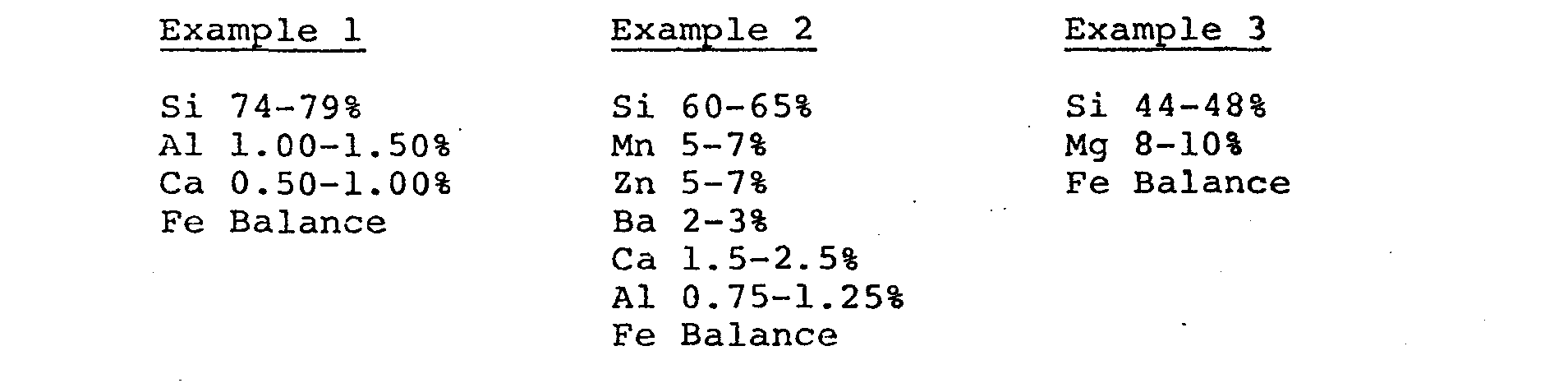
- Example 1 above is identified as "Grade 75% ferrosilicon", Example 2 is identified as "SMZ Alloy", and Example 3 is identified as "9% magnesium-ferrosilicon", all of which are manufactured by Union Carbide Corporation, Ferroalloys Division, Buffalo, New York. Within each example the individual particles have the same respective alloy composition.
- As noted in the above examples, the treating
agent 16 normally contains small portions of one or more additional elements in addition to the ferrosilicon constituent such as aluminum, calcium, manganese, zirconium, barium, magnesium, strontium, cerium and the rare earth elements. - We have found it necessary to compact the particulated treating
agent 16 within theconduit 12 to a relatively dense state in order to assure rapid internal dissolution of the conduit. For example, the preferred density of the core is equivalent to a degree of compaction in excess of 10% above the tapped density thereof. The term "tapped density" as used herein, refers to the known procedure described in "HANDBOOK OF METAL POWDERS" - Poster, Reinhold Publishing Co., New York, New York, 1966, page 57. - The
second material 18 of thecore 14, on the other hand, is a liquifying agent that preferably has little effect upon the casting's metallurgical structure. In the embodiment of FIGS. 1 and 2, the liquifying agent is a coating ortubular member 24 bonded to theinternal surface 20 of theferrous metal conduit 12. Preferably, the liquifying agent is a material selected from the group consisting of copper, aluminum, phosphorus, sulfur, tin and zinc plus impurities, and alloys of these materials having a melting temperature less than about 1200°C (2192°F). Also suitable are alloys containing manganese and boron in combination with one or more of the aforementioned materials of the group having a melting temperature less than about 12000C (2192°F). We contemplate that bronzes, brass and aluminum bronze are suitable liquifying agents. Theliquifying agent 18 preferably should have a melting temperature below the melting temperature of the treatingagent 16 or alternately must have greater diffusitivity than the treating agent with respect to the material of theconduit 12. - A second embodiment of the filled
tubular article 10 is illustrated in FIG. 3 and is generally the same as the previously described embodiment, only it differs therefrom by having a liquifying agent or coating 26 bonded to theexternal surface 22 of theconduit 12 in addition to theinternal coating 24. Preferably, theoptional coating 26 is of a material selected from the same group as set forth above with respect to thesecond material 18. Theexterior coating 26 can add to the speed of dissolution of theexternal surface 22 of theconduit 12 when the material of the coating and material of the molten metal in which the conduit is immersed have improved wetability with respect to each other over that of the conduit itself and the molten metal. It should be understood, however, that the external coating must have a melting temperature below the temperature of the molten metal. - In operation, the second embodiment filled
tubular article 10 having the aforementioned Grade 75%ferrosilicon treating agent 16, the low carbonmild steel conduit 12, the internal copper coating or cladding 24, and the external copper coating orcladding 26 was dipped for a preselected period of time into a still bath of molten iron at various preselected temperatures below the melting temperature of the conduit. The conduit had a thickness T as indicated in FIG. 2 of 0.38 mm (.015") with a layer of copper 0.03 mm (.0012") thick on the outside diameter and a layer of copper 0.05 mm (.0019") thick on the inside diameter. The melting temperature of the Grade 75% ferrosilicon treating agent was about 13100C (2390°F), and the melting temperature of the copper was about 1080°C (1975°F), and even though the melting point of the steel conduit was about 1540°C (2805°F) it was determined that the total dissolution rate of the filled tubular article constructed in accordance with the present invention was about 50% greater than a comparison filled tubular article of similar dimensions without either the internal or external copper cladding. In this regard, reference is made to the graph of FIG. 4 showing in the vertical direction the rate of internal dissolution or amount of radial liquification per unit of time of theinternal surface 20, of the conduit versus the temperature of the molten iron bath in the horizontal direction. Thelower curve 28 represents the internal dissolution rate for dip tests of prior art inoculating articles solely having asteel conduit 12 and a Grade 75% ferrosilicon treating agent, while theupper curve 30 represents dip tests of the second embodiment articles with internal and external copper cladding. - Metallurgical examination of a comparison prior art filled tubular article and the article of the instant invention after the above described dipping procedure indicated that the dissolution mechanism was different for each one. In the second embodiment filled
tubular article 10, the austenite grain boundaries of the steel conduit were attacked or penetrated by the liquified copper. The greatly advanced rate of dissolution of theinternal surface 20 that was realized was directly attributable to the rapid rate of liquification of the copper and its liquid metal embrittlement attack of the steel conduit. In contrast, the prior art filled tubular articles dissolved internally through a much slower solid state diffusion process. - Referring now to a third embodiment of the present invention as illustrated in FIG. 5, the
elongated metal conduit 12 has a core 32 that includes first and second discreteparticulate materials first material 34 is preferably a treating agent similar to the treatingagent 16 described above with respect to the first and second embodiments. Preferably also, thesecond material 36 is similar to those liquifyingagents 18 described with respect to the first and second embodiments. - In operation, three different filled
tubular articles 10 constructed in accordance with the third embodiment. of the present invention and several prior art filled tubular articles for comparison were dipped for preselected periods of time into a still bath of molten iron at various preselected temperatures below the melting temperature of theconduit 12. The conduit in each instance had the same dimensions and was of low carbon mild steel having the previously stated composition and a melting point of about 1540°C (2805°F) as previously noted, and in each instance the core was densified to a level in excess of 10% above the tapped density. The composition of the core 32 by weight was varied in order to better determine the dissolution characteristics of each example as follows:
- In each of the above three examples the second , particulate material or liquifying agent 3& consisted of particles of substantially pure copper capable of passing through a fine mesh sieve such as a No. 200 Sieve (0.075 mm nominal diameter of the opening), and preferably between a range of Standard Test Sieve Nos. 325 to 400 (0.045 mm to 0.038 mm nominal diameter of the openings). In each of the above three examples also, and in a prior art article which did not have a liquifying agent such as the copper, the previously described Grade 75% ferrosilicon was used as the first particulate material or treating
agent 34. The Example A weight proportion or ratio of the liquifyingagent 36 to the treatingagent 34 was specifically chosen to be similar to that proportion established in the second embodiment utilizing thecopper coating 24 within theconduit 12. - It was found through the aforementioned tests that the internal dissolution rate of the Example A third embodiment filled
tubular article 10 using 10.8 wt. % copper particles was substantially similar to the second embodiment utilizing the equivalent amount of weight of copper coating. However, the dissolution mechanism was different therebetween. The particulated and thoroughly distributed copper in the third embodiment articles initially liquifies and reacts with the particulate ferrosilicon material to form an intermediate "semi-eutectic" liquid solution of silicon, copper and iron having properties that desirably approaches those of a eutectic liquid solution for rapidly and progressively dissolving or attacking the conduit. Copper forms a low melting eutectic with silicon, for example, and at 16% silicon and 84% copper the melting point is 802°C (1475°F). It was further observed that the internal dissolution rates of the Example B and Example C proportions were undesirably ,< less than the Example A embodiments. Therefore, even though the total weight of copper in Example B was twice Example A, there was no commensurate gain in the dissolution rate. - Accordingly, we have concluded that a weight proportion of a liquifying agent'18, such as the copper in either cladding or particulate form, in excess of about 20% relative to the core 14 would not result in a sufficient increase in the internal rate of dissolution of the
steel conduit 12 to justify the expense of the excess amount of liquifying agent. Also, adding more than 20% of the liquifying agent could be deleterious to the molten iron. Moreover, any increase in the amount of liquifying agent would necessarily result in distributing a lesser proportion of treatingagent 16 to the molten metal at the same feed rate. For these reasons, the proportion of liquifyingagent 18 is preferably limited to less than about 15% by weight. On the other hand, we believe that a weight proportion of liquifying agent less than about 5% of the core would result in an insignificant degree of improvement of the internal dissolution rate of the conduit when compared with a prior art filled tubular article. - Referring now to FIG. 6, a fourth embodiment of the instant invention is illustrated, with similar reference numbers being applied thereto to designate elements comparable to those of FIGS. 1, 2, 3 and 5. In FIG. 6, however, the second material or liquifying
agent 18 is shown in the form of acoating 38 on the individual particles of the first material or treatingagent 16. Specifically, while the coating can be any of the materials listed above with respect to the first embodiment, such coating is preferably a metal coating selected from the group consisting of copper, tin, bronze and brass. For example, a copper coating on the previously described Grade 75% ferrosilicon particles. Such copper coating can be applied to the ferrosilicon particles by a conventional mulling operation. Upon immersing thearticle 10 of FIG. 6 in molten metal, thecoating 38 will quickly liquify and react with the treatingagent 16 to initially provide a transitory or intermediate "semi-eutectic" liquid in a manner comparable to the reaction described previously with respect to FIG. 5, which liquid will subsequently dissolve theinternal surface 20 of theconduit 12 at a relatively rapid rate. - In view of the foregoing, it is readily apparent that the filled
tubular article 10 of the subject invention can be controllably inserted into molten metal for altering same as is disclosed, for example, in more detail in U.S. Patent No. 3,991,808 issued to John R. Nieman, et al on November 16, 1976. More importantly, however, its rate of feed into the melt can be increased substantially in comparison with prior aj=t articles primarily because of its faster rate of internal dissolution. Such faster rate of internal dissolution is directly attributable to the intimate contact of the chemically discrete materials of the liquifyingagent 18 and treatingagent 16 within the core. In general, the lower the melting point of the liquifying agent below the preferred maximum melting temperature of the liquifyingagent 18 at about 1200°C (2192°F), the quicker melting will occur and a liquid-solid reaction will start with the ferrous composition of the conduit. However, it is also to be recognized that the composition of the liquifying agent must not form high melting temperature intermetallic compounds within the tubular article and must be wet or soluble with the ferrous metal of the conduit. Preferably too, the quantity of the treatingagent 16 and liquifyingagent 18 is restricted to a preselected range as previously noted. - We contemplate that the amount of liquifying
agent 18 should be broadly maintained at about 5 to 20% of the total weight of the core 14, and the treating agent should make up the remainder or about 80 to 95% of the weight of the core. Preferably, the amount of liquifying agent should be maintained at about 8 to 15% of the total weight of the core, and specifically at about 10%. Alternately, the thickness of thecoating 24 on the inside of the conduit should be about 5% to 15% of a preselected thickness T of the conduit, and preferably about 10% T. - It is important to recognize that in the
article 10 of the present invention the treatingagent 16 and the liquifyingagent 18 not only are in intimate contact but also are discrete chemically, with the liquifying agent promoting a rapid melting of the internal surface of theconduit 12 by either direct action upon the conduit or by forming a low melting point eutectic alloy with the treating agent and subsequent reaction attack of the conduit. This contrasts to prior art use of magnesium and magnesium alloys in a steel conduit that have not promoted a faster rate of internal dissolution of the conduit. For example, magnesium is substantially insoluble in steel and, hence, would not accelerate internal dissolution. Moreover, magnesium and a treating agent have existed heretofore as a reaction product or combined alloy within a steel conduit so that the rate of any reaction attack on the conduit has been minimal. Still further, magnesium often forms undesirable intermetallic compounds in or with the molten metal. On the other hand, the liquifyingagent 18 controllably liquifies and accelerates the dissolving of the conduit independent of any substantial degree of alloying influence upon the molten metal. - Other aspects, objects and advantages will become apparent from a study of the specification, drawings and appended claims.
Claims (21)
Applications Claiming Priority (2)
| Application Number | Priority Date | Filing Date | Title |
|---|---|---|---|
| US05/900,634 US4174962A (en) | 1978-04-27 | 1978-04-27 | Filled tubular article for controlled insertion into molten metal |
| US900634 | 1978-04-27 |
Publications (2)
| Publication Number | Publication Date |
|---|---|
| EP0005152A1 true EP0005152A1 (en) | 1979-11-14 |
| EP0005152B1 EP0005152B1 (en) | 1983-01-19 |
Family
ID=25412835
Family Applications (1)
| Application Number | Title | Priority Date | Filing Date |
|---|---|---|---|
| EP79100594A Expired EP0005152B1 (en) | 1978-04-27 | 1979-02-28 | Filled tubular article for controlled insertion into molten metal |
Country Status (3)
| Country | Link |
|---|---|
| US (1) | US4174962A (en) |
| EP (1) | EP0005152B1 (en) |
| DE (1) | DE2964519D1 (en) |
Cited By (1)
| Publication number | Priority date | Publication date | Assignee | Title |
|---|---|---|---|---|
| EP0546351A2 (en) * | 1991-11-21 | 1993-06-16 | SKW Trostberg Aktiengesellschaft | Cored wire containing a passivated pyrophoric metal and its application |
Families Citing this family (16)
| Publication number | Priority date | Publication date | Assignee | Title |
|---|---|---|---|---|
| CA1151835A (en) * | 1979-02-17 | 1983-08-16 | Jan O. Kristiansen | Metallurgical pouring vessels |
| IT1162307B (en) * | 1979-04-27 | 1987-03-25 | Centro Speriment Metallurg | METHOD FOR THE INTRODUCTION OF DIOXIDE-DEDOLFORANT SUBSTANCES UNDER THE BATTERN OF LIQUID METALS WITHOUT THE USE OF GASEOUS VEHICLES |
| FR2476542B1 (en) * | 1980-02-26 | 1983-03-11 | Vallourec | |
| US4795066A (en) * | 1982-09-23 | 1989-01-03 | Kaiser Steel Corporation | Ladle nozzle insert |
| NL8600314A (en) * | 1986-02-10 | 1987-09-01 | Hoogovens Groep Bv | POWDER FILLED TUBE AND METHOD FOR CONTINUOUSLY MANUFACTURING SUCH A TUBE. |
| FR2594850A1 (en) * | 1986-02-24 | 1987-08-28 | Vallourec | TUBULAR ENCLOSED COMPOSITE PRODUCT COMPRISING COMPACT MATERIAL FOR THE TREATMENT OF LIQUID METALS AND PROCESS FOR PRODUCING THE SAME |
| FR2630131B1 (en) * | 1988-04-14 | 1990-08-03 | Affival | PROCESS FOR DESULFURIZING THE CAST |
| US6346135B1 (en) * | 1998-12-10 | 2002-02-12 | Minerals Technologies Inc. | Cored wire for treating molten metal |
| US6830632B1 (en) | 2002-07-24 | 2004-12-14 | Lucas Milhaupt, Inc. | Flux cored preforms for brazing |
| PL1945397T3 (en) * | 2005-11-10 | 2016-08-31 | Lucas Milhaupt Inc | Brazing material with continuous length layer of elastomer containing a flux |
| PL2038085T3 (en) * | 2006-05-25 | 2020-03-31 | Bellman-Melcor Development, Llc | Wire with flux for brazing and soldering and method of making the same |
| US8274014B2 (en) | 2006-05-25 | 2012-09-25 | Bellman-Melcor Development, Llc | Filler metal with flux for brazing and soldering and method of making and using same |
| WO2008073419A2 (en) | 2006-12-11 | 2008-06-19 | Lucas Milhaupt, Inc. | Low and non-silver filler metals and alloys and corresponding joinder systems and methods |
| US9157134B2 (en) | 2009-10-26 | 2015-10-13 | Lucas-Milhaupt, Inc. | Low silver, low nickel brazing material |
| US9731383B2 (en) | 2014-07-09 | 2017-08-15 | Bellman-Melcor Development, Llc | Filler metal with flux for brazing and soldering and method of using same |
| US10744601B2 (en) | 2015-08-07 | 2020-08-18 | Bellman-Melcor Development, Llc | Bonded brazing ring system and method for adhering a brazing ring to a tube |
Citations (6)
| Publication number | Priority date | Publication date | Assignee | Title |
|---|---|---|---|---|
| DE1558286A1 (en) * | 1967-06-21 | 1970-03-19 | Purmetall Ges Fuer Stahlveredl | Device for the metered addition of aggregates |
| FR2085306A1 (en) * | 1970-04-08 | 1971-12-24 | Loire Atel Forges | Auxiliary appts for ingot moulds - enabling introduction of solid additives |
| DE2519275A1 (en) * | 1974-05-01 | 1975-11-06 | Hitachi Cable | METHOD FOR CONTINUOUS STEEL CASTING |
| DE2531573A1 (en) * | 1974-07-15 | 1976-01-29 | Caterpillar Tractor Co | COMPOSITION AND METHOD OF ADDING IT TO A METAL MELT |
| GB1439430A (en) * | 1973-12-10 | 1976-06-16 | Metallurg Exoproducts Corp | Ladle addition apparatus |
| DE2810797A1 (en) * | 1977-03-14 | 1978-09-21 | Caterpillar Tractor Co | IMPARTICLE |
Family Cites Families (13)
| Publication number | Priority date | Publication date | Assignee | Title |
|---|---|---|---|---|
| US2154613A (en) * | 1936-08-08 | 1939-04-18 | Robert G Guthrie | Method for producing alloys |
| US2086756A (en) * | 1936-10-17 | 1937-07-13 | Francis J Whitaker | Method of making open hearth steel and flux employed in such method |
| US2397418A (en) * | 1944-09-25 | 1946-03-26 | John J Howard | Means for refining metals |
| US2873188A (en) * | 1956-02-10 | 1959-02-10 | Union Carbide Corp | Process and agent for treating ferrous materials |
| US3056190A (en) * | 1960-04-06 | 1962-10-02 | Dow Chemical Co | Composite metal article and method of making same |
| US3367395A (en) * | 1965-05-12 | 1968-02-06 | Quebec Iron & Titanium Corp | Method and apparatus for treating molten metals |
| US3534390A (en) * | 1968-04-29 | 1970-10-13 | Stoody Co | Welding wire |
| US3942775A (en) * | 1973-04-02 | 1976-03-09 | Labate Michael D | Submerged desulphurization device and method |
| US3934862A (en) * | 1973-04-12 | 1976-01-27 | Labate Michael D | Device for supplying a treating agent to molten metal in a ladle |
| US3991808A (en) * | 1974-07-15 | 1976-11-16 | Caterpillar Tractor Co. | Method and apparatus for the introduction of additives into a casting mold |
| US4043798A (en) * | 1974-09-20 | 1977-08-23 | Sumitomo Metal Industries Limited | Process for producing steel having improved low temperature impact characteristics |
| GB1518516A (en) * | 1975-08-13 | 1978-07-19 | Aikoh Co | Desulphurizing and inoculating agent for molten iron |
| US4052202A (en) * | 1975-09-25 | 1977-10-04 | Reactive Metals & Alloys Corporation | Zirconium alloy additive and method for making zirconium additions to steels |
-
1978
- 1978-04-27 US US05/900,634 patent/US4174962A/en not_active Expired - Lifetime
-
1979
- 1979-02-28 EP EP79100594A patent/EP0005152B1/en not_active Expired
- 1979-02-28 DE DE7979100594T patent/DE2964519D1/en not_active Expired
Patent Citations (6)
| Publication number | Priority date | Publication date | Assignee | Title |
|---|---|---|---|---|
| DE1558286A1 (en) * | 1967-06-21 | 1970-03-19 | Purmetall Ges Fuer Stahlveredl | Device for the metered addition of aggregates |
| FR2085306A1 (en) * | 1970-04-08 | 1971-12-24 | Loire Atel Forges | Auxiliary appts for ingot moulds - enabling introduction of solid additives |
| GB1439430A (en) * | 1973-12-10 | 1976-06-16 | Metallurg Exoproducts Corp | Ladle addition apparatus |
| DE2519275A1 (en) * | 1974-05-01 | 1975-11-06 | Hitachi Cable | METHOD FOR CONTINUOUS STEEL CASTING |
| DE2531573A1 (en) * | 1974-07-15 | 1976-01-29 | Caterpillar Tractor Co | COMPOSITION AND METHOD OF ADDING IT TO A METAL MELT |
| DE2810797A1 (en) * | 1977-03-14 | 1978-09-21 | Caterpillar Tractor Co | IMPARTICLE |
Cited By (3)
| Publication number | Priority date | Publication date | Assignee | Title |
|---|---|---|---|---|
| EP0546351A2 (en) * | 1991-11-21 | 1993-06-16 | SKW Trostberg Aktiengesellschaft | Cored wire containing a passivated pyrophoric metal and its application |
| EP0546351A3 (en) * | 1991-11-21 | 1993-12-29 | Sueddeutsche Kalkstickstoff | Cored wire containing a passivated pyrophoric metal and its application |
| TR26635A (en) * | 1991-11-21 | 1995-03-15 | Sueddeutsche Kalkstickstoff | USING THE PASSIFIED Pyrophoric METAL NEEDED WIRE WIRE AND IT |
Also Published As
| Publication number | Publication date |
|---|---|
| US4174962A (en) | 1979-11-20 |
| EP0005152B1 (en) | 1983-01-19 |
| DE2964519D1 (en) | 1983-02-24 |
Similar Documents
| Publication | Publication Date | Title |
|---|---|---|
| EP0005152B1 (en) | Filled tubular article for controlled insertion into molten metal | |
| Pai et al. | Production of cast aluminium-graphite particle composites using a pellet method | |
| JPH04231435A (en) | Strontium-containing magnesium alloy with high mechanical strength and preparation thereof by means of rapid coagulation | |
| EP1126037B1 (en) | Production of nodular cast iron involving a preliminary inoculation in the casting ladle | |
| US3833361A (en) | Method for adding special elements to molten pig iron | |
| US2881068A (en) | Method of treating a ferrous melt with a porous sintered metal body impregnated with a treating agent | |
| SU928831A1 (en) | Alloy for steel treatment | |
| EP0066305B1 (en) | Additive in wire form for treating molten metals | |
| US4889688A (en) | Process of producing nodular cast iron | |
| US3459541A (en) | Process for making nodular iron | |
| DE2948636A1 (en) | WIRE-SHAPED AGENT FOR TREATING METAL MELT | |
| US4175918A (en) | Elongate consolidated article and method of making | |
| RU2375462C2 (en) | Wire for out-of-furnace treatment of metallurgical melts | |
| US3321304A (en) | Materials for and methods of treating molten ferrous metals to produce nodular iron | |
| US4088475A (en) | Addition of reactive elements in powder wire form to copper base alloys | |
| US4430295A (en) | Articles produced from iron powder compacts containing hypereutectic copper phosphide powder | |
| US6139654A (en) | Strontium master alloy composition having a reduced solidus temperature and method of manufacturing the same | |
| CA1107075A (en) | Elongate composite article | |
| US4801328A (en) | Deoxidizing agent | |
| US2874038A (en) | Method of treating molten metals | |
| US1945260A (en) | Composition of matter and process of treating molten metals | |
| US3113019A (en) | Nodular iron production | |
| JPH07207316A (en) | Wire for desulfurization of molten iron having high desulfurization efficiency | |
| SU1046316A1 (en) | Modifier for cast iron | |
| US3984233A (en) | Ferrous metal network impregnated with rare earth metals |
Legal Events
| Date | Code | Title | Description |
|---|---|---|---|
| PUAI | Public reference made under article 153(3) epc to a published international application that has entered the european phase |
Free format text: ORIGINAL CODE: 0009012 |
|
| AK | Designated contracting states |
Designated state(s): DE FR |
|
| 17P | Request for examination filed | ||
| GRAA | (expected) grant |
Free format text: ORIGINAL CODE: 0009210 |
|
| AK | Designated contracting states |
Designated state(s): DE FR |
|
| REF | Corresponds to: |
Ref document number: 2964519 Country of ref document: DE Date of ref document: 19830224 |
|
| ET | Fr: translation filed | ||
| PGFP | Annual fee paid to national office [announced via postgrant information from national office to epo] |
Ref country code: FR Payment date: 19840203 Year of fee payment: 6 |
|
| PGFP | Annual fee paid to national office [announced via postgrant information from national office to epo] |
Ref country code: DE Payment date: 19840319 Year of fee payment: 6 |
|
| PG25 | Lapsed in a contracting state [announced via postgrant information from national office to epo] |
Ref country code: FR Free format text: LAPSE BECAUSE OF NON-PAYMENT OF DUE FEES Effective date: 19851031 |
|
| PG25 | Lapsed in a contracting state [announced via postgrant information from national office to epo] |
Ref country code: DE Effective date: 19851101 |
|
| REG | Reference to a national code |
Ref country code: FR Ref legal event code: ST |
|
| PLBE | No opposition filed within time limit |
Free format text: ORIGINAL CODE: 0009261 |
|
| STAA | Information on the status of an ep patent application or granted ep patent |
Free format text: STATUS: NO OPPOSITION FILED WITHIN TIME LIMIT |