EP0004989A1 - Installation de soudage par induction pour la fabrication de tubes - Google Patents
Installation de soudage par induction pour la fabrication de tubes Download PDFInfo
- Publication number
- EP0004989A1 EP0004989A1 EP79200165A EP79200165A EP0004989A1 EP 0004989 A1 EP0004989 A1 EP 0004989A1 EP 79200165 A EP79200165 A EP 79200165A EP 79200165 A EP79200165 A EP 79200165A EP 0004989 A1 EP0004989 A1 EP 0004989A1
- Authority
- EP
- European Patent Office
- Prior art keywords
- concentrator
- external
- installation according
- tube blank
- blank
- Prior art date
- Legal status (The legal status is an assumption and is not a legal conclusion. Google has not performed a legal analysis and makes no representation as to the accuracy of the status listed.)
- Granted
Links
- 238000009434 installation Methods 0.000 title claims abstract description 33
- 230000006698 induction Effects 0.000 title claims abstract description 31
- 238000003466 welding Methods 0.000 title claims abstract description 21
- 238000004519 manufacturing process Methods 0.000 title claims abstract description 6
- 238000005242 forging Methods 0.000 claims abstract description 25
- 238000011144 upstream manufacturing Methods 0.000 claims abstract description 25
- 239000004020 conductor Substances 0.000 claims description 6
- RYGMFSIKBFXOCR-UHFFFAOYSA-N Copper Chemical compound [Cu] RYGMFSIKBFXOCR-UHFFFAOYSA-N 0.000 claims description 4
- 229910052802 copper Inorganic materials 0.000 claims description 4
- 239000010949 copper Substances 0.000 claims description 4
- 239000000463 material Substances 0.000 claims description 3
- 230000004224 protection Effects 0.000 claims description 3
- 230000000087 stabilizing effect Effects 0.000 claims description 3
- 230000005611 electricity Effects 0.000 claims description 2
- XAGFODPZIPBFFR-UHFFFAOYSA-N aluminium Chemical compound [Al] XAGFODPZIPBFFR-UHFFFAOYSA-N 0.000 claims 1
- 229910052782 aluminium Inorganic materials 0.000 claims 1
- 239000000696 magnetic material Substances 0.000 claims 1
- XKRFYHLGVUSROY-UHFFFAOYSA-N Argon Chemical compound [Ar] XKRFYHLGVUSROY-UHFFFAOYSA-N 0.000 description 8
- -1 for example Substances 0.000 description 7
- 229920001343 polytetrafluoroethylene Polymers 0.000 description 5
- 239000004810 polytetrafluoroethylene Substances 0.000 description 5
- 230000006641 stabilisation Effects 0.000 description 5
- 238000011105 stabilization Methods 0.000 description 5
- 229910052786 argon Inorganic materials 0.000 description 4
- 239000002826 coolant Substances 0.000 description 4
- 239000002184 metal Substances 0.000 description 4
- 229910052751 metal Inorganic materials 0.000 description 4
- 229910001220 stainless steel Inorganic materials 0.000 description 4
- 239000010935 stainless steel Substances 0.000 description 4
- 239000000498 cooling water Substances 0.000 description 3
- QVGXLLKOCUKJST-UHFFFAOYSA-N atomic oxygen Chemical compound [O] QVGXLLKOCUKJST-UHFFFAOYSA-N 0.000 description 2
- 230000000694 effects Effects 0.000 description 2
- 238000010438 heat treatment Methods 0.000 description 2
- 239000011261 inert gas Substances 0.000 description 2
- 239000001301 oxygen Substances 0.000 description 2
- 229910052760 oxygen Inorganic materials 0.000 description 2
- 239000003507 refrigerant Substances 0.000 description 2
- XLYOFNOQVPJJNP-UHFFFAOYSA-N water Substances O XLYOFNOQVPJJNP-UHFFFAOYSA-N 0.000 description 2
- VVQNEPGJFQJSBK-UHFFFAOYSA-N Methyl methacrylate Chemical compound COC(=O)C(C)=C VVQNEPGJFQJSBK-UHFFFAOYSA-N 0.000 description 1
- 229920005372 Plexiglas® Polymers 0.000 description 1
- 239000011324 bead Substances 0.000 description 1
- 238000007664 blowing Methods 0.000 description 1
- 238000001816 cooling Methods 0.000 description 1
- 238000005520 cutting process Methods 0.000 description 1
- 230000007423 decrease Effects 0.000 description 1
- 239000012777 electrically insulating material Substances 0.000 description 1
- 230000005672 electromagnetic field Effects 0.000 description 1
- 230000008030 elimination Effects 0.000 description 1
- 238000003379 elimination reaction Methods 0.000 description 1
- 230000002349 favourable effect Effects 0.000 description 1
- 239000011810 insulating material Substances 0.000 description 1
- 238000009413 insulation Methods 0.000 description 1
- 150000002739 metals Chemical class 0.000 description 1
- 238000013021 overheating Methods 0.000 description 1
- 230000001681 protective effect Effects 0.000 description 1
- 238000007790 scraping Methods 0.000 description 1
- 229910000679 solder Inorganic materials 0.000 description 1
Images



Classifications
-
- B—PERFORMING OPERATIONS; TRANSPORTING
- B23—MACHINE TOOLS; METAL-WORKING NOT OTHERWISE PROVIDED FOR
- B23K—SOLDERING OR UNSOLDERING; WELDING; CLADDING OR PLATING BY SOLDERING OR WELDING; CUTTING BY APPLYING HEAT LOCALLY, e.g. FLAME CUTTING; WORKING BY LASER BEAM
- B23K13/00—Welding by high-frequency current heating
- B23K13/01—Welding by high-frequency current heating by induction heating
- B23K13/02—Seam welding
- B23K13/025—Seam welding for tubes
Definitions
- the present invention relates to an induction welding installation for the manufacture of tubes at speeds substantially higher than those obtained so far.
- the invention applies mainly to stainless steel tubes, but tubes of other metals can also be welded with advantage in the installation according to the invention.
- Induction welding installations for the manufacture of tubes are known per se and described, for example in US Pat. Nos. 1,365,198 and US 2,687,464. They include means for transporting a blank of tube to be welded through a coil of induction connected to an alternating current generator. The induced currents generated in the tube blank are used to heat the edges up to a temperature sufficient to weld them under the effect of a force which presses them against each other, exerted by forging rollers located downstream of the induction coil.
- an induction welding installation for the manufacture of tubes comprising an induction coil surrounding a tube blank whose edges determine a slit which narrows downstream, forging rollers located downstream of the induction coil applying the heated edges of the blank against each other at the location of a welding point located near a plane connecting the axes of the forging rollers and an internal concentrator disposed at the interior of the blank is characterized in that the internal concentrator comprises a stack of magnetizable sheets oriented parallel to the diameter of the tube passing through the slot of the blank and of length greater than the distance between the upstream end of the coil and the axes of the forging rollers.
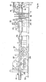
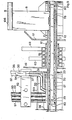
- Figutes IA and IB are the two parts of a single and same elevation view of a tube welding installation according to the invention.
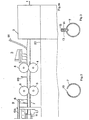
- Figures 2 and 3 are sections of a tube blank before welding.
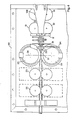
- Figure 4. is a plan view and Figure 5 a sectional view of the tube welding installation shown in Figures 1 and 2 in the vicinity of the induction coil.
- Figure 6 shows the current leads to the induction coil.
- Figures 7, 8 and 8A are respectively a section along X-X and other views of the arrangement shown in Figure 6.
- Figures 9 and 10 are a sectional view and a plan view of an external concentrator.
- Figure II shows a device for mounting the external hub.
- Figures 12, 13 and 14 are sectional views, in plan and in elevation of the external concentrator.
- Figure 15 is an elevational view and Figure 16 a plan view of a support device for the external concentrator.
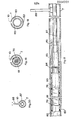
- Figures 17, 18, 19 and 20 are a longitudinal sectional view and several cross-sectional views of an internal concentrator.
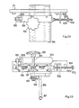
- Figures 21, 22, 23 and 24 are views of a support device and of controlling the position of the internal concentrator.
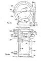
- Figures 25 and 26 are two views of a device for cooling and protecting the forging rollers of the installation.
- Figures 1A and 1B are intended to be assembled along the lines to the right of Figure 1A and to the left of Figure 1B to form a single figure.
- a food coil not shown
- This sheet first passes through part 2 of the installation where various forming rollers are not described in detail, because 'They are not part of the invention.
- a support and control device 3 for the position of an internal concentrator described in more detail later.
- the sheet has the shape of a tube blank 7.
- an upstream support blade 8 a support device and stabilization 9 of an internal concentrator passes through a slot 10 between the edges of the tube blank 7 (see FIG. 2).
- the tube blank then passes through two pairs of forming rollers II and 12 between which a roller 13 with metal flanges 14 ensures the correct position of the blank 7 and adjusts the width of the slot 10 (FIG. 3).
- an insulating body 15 is arranged between the metal flanges 14 of the roller 13 to prevent the creation of a conductive path through the flanges 14 between the edges of the tube blank 7 on either side of the slot 10.
- a support blade 16 of the support device 9 of the internal concentrator passes through the slot 10 at the height of the forming rollers 12.
- a screen of electrically conductive material 17 pierced with a hole slightly larger than the section of the tube blank 7 is placed near and upstream of an induction coil. 18 described in detail later.
- the induction coil generates eddy currents in the tube blank 7. These currents heat the edges of the slot 10 and bring them to the welding temperature.
- Another screen 19 made of electrically conductive material is arranged downstream of the induction coil 18. Beyond this screen 19 is arranged an external concentrator 20 described in detail later.
- the external concentrator 20 serves as a support for a system of tubes 21 for supplying inert gas which is blown on the tube blank 7 between the induction coil 18 and a pair of forging rollers 23. Some of the tubes 21 convey a refrigerant for the external concentrator 20, for example cooling water.
- the forging rollers 23 press against each other the edges of the tube blank 7 at a point close to a plane 24 passing through the axes of the rollers 23. Downstream of the forging rollers 23, clamping rollers 25 and 26 ( Figure 4) are provided. They have the effect of properly stabilizing the tube blank 7 in the upstream region, that is to say at the location of the forging rollers 23. Then the installation is conventional and includes scraping tools 27 for removing the extra thickness of the weld bead, and other rollers 28, 29, 30 which lead the finished tube to a cutting station not shown.
- the components of the installation which are responsible for the advantages of the invention and in particular for allowing the welding of stainless steel tubes at particularly high speeds are the internal concentrator, the external concentrator, the induction coil, the support and position control devices of the internal concentrator, the protection devices of the forging rollers and the stabilization system of the tube blank as it travels through the welding installation.
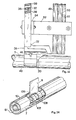
- the external concentrator 20 shown in FIGS. 1A, 4, 5 and 9 to 14 is a metallic piece, not magnetic, but producing electricity, for example made of copper. It is disposed above the slot 10 of the tube blank 7 between the induction coil 18 and the plane 24 passing through the axes of the forging rollers 23.
- the shape of the external concentrator is shown in Figures 9,10 and 12.
- the concentrator 20 is constituted by a curved body 31 which extends along the contour of the tube blank 7 on either side of a central upper region 32 covering the slot 10.
- the plane of symmetry of the external concentrator 20 passes through the longitudinal axis of the tube blank 7. At the upstream end of the external concentrator (on the right in FIGS.
- the coprs 31 envelops the tube blank at an angle measuring approximately 240 ° (figure 12). This angular extension is maintained up to a point 33 downstream from the upstream end. From point 33 the angular extension of the body 31 decreases so that its edge follows curves 34 and 35 shown in plan in Figures 4 and 10 and in elevation in Figure 9.
- the external concentrator 20 occupies a wedge-shaped space between the forging rollers 23 and has parts called skirts with curved edges which extend laterally from the central region 32.
- the external concentrator 20 supports, or conversely is supported by, a set of four tubes 36, 37, 38 and 39 secured to it at the top.
- the tube 36 ends in a horizontal part fixed to the central upper region 32.
- This horizontal part comprises a series of openings 40 which communicate with openings 41 in the concentrator 20.
- These openings 40 and 41 make it possible to blow an inert gas, for example, argon in the space under the external concentrator and keep oxygen from the air in the welding area.
- An additional supply of argon is introduced through the tube 37 which ends in a blowing nozzle made of electrical insulating material 42 at the downstream end 43 of the concentrator.
- Tubes 38 and 39 serve to convey a coolant, for example water which sprinkles the skirts of the external concentrator.
- the tubes 36 to 39 are preferably made of copper and assembled in a single package per solder.
- An additional arrangement of the external concentrator is constituted by a pair of handwheels 44 and 45 shown in FIG. 12.
- the handwheels 44 and 45 are fixed to the skirts by screws 46 and curved clamping plates 47 and 48 and come inside skirts to be applied resiliently on the tube blank 7.
- the flywheels 44 and 45 prevent the argon from escaping from the space below the concentrator and force it to lick the edges of the slot 10 .
- Additional argon is further supplied by tubes 49, 50 and 51 arranged upstream and in the immediate vicinity of the constriction between the forging rollers 23 in order to exclude oxygen from the welding zone.
- the tubes 49, 50 and 51 made of polytetrafluoroethylene for example, are secured to the bundle of tubes 36, 37, 38 and 39 for example by means of a clamp 52 (FIG. 13).
- the external concentrator 20 is supported from a frame 53 of the installation by means of a positioning device allowing fine adjustments in the three dimensions x, y, z.
- the package of tubes 36 to 39 is fixed to a bar 54 (FIGS. 5, 11, 15 and 16) mounted on a column 55.
- the column 55 is secured to a slide 56, itself connected to a slide 57.
- the movement (direction x) between the slide 56 and its support 57 is controlled by a lead screw 58.
- the movement (direction y) of the slide 57 relative to the frame 53 is perpendicular to the movement between the elements 56 and 57 and is also controlled by a lead screw 59.
- the movement between the bar 54 and the column 55 (vertical direction z) is also controlled by a lead screw 60.
- the induction coil 18 comprises five turns of a square section tube traversed by cooling water.
- the turns of the coil 18 are wound on an insulating support 61, for example made of polytetrafluoroethylene, the bore of which is slightly larger than the section of the tube blank 7.
- the turns of the coil 18 are arranged in perpendicular vertical planes to the axis of the blank 7. They are connected to each other and to the feed by portions of conductor arranged on the side opposite to the slot (10) of the blank (Fig.8B).
- connections 62 and 63 are clamped by washers 64 and 65 on conductive plates 66 and 67 separated by an insulating layer 68, for example made of polytetrafluoroethylene (FIG. 7) Thanks to such an arrangement, the necessary electrical energy is brought to work in sufficient quantity.
- the connections 62 and 63 extend beyond their point of attachment at the location of the washers 64 and 65 to be connected to cooling water tubes not shown.
- the conductive plates 66 and 67 are lined with plates 69 and 70, for example made of plexiglass, interconnected by lag screws 71.
- a stabilization bar 72 between the the end of the coil support and the frame 53 provides additional stability for the induction coil 18.
- the electrical supply is mounted on a carriage 73 which can be moved on rails 74 by means of wheels 75.
- the stabilization bar 72 comprises buttonholes 76 (FIG. 6) through which tightened bolts 77 pass as soon as the correct position of the reel 18 is adjusted by the movement of the carriage 73 on the rails 74.
- the internal concentrator is shown in FIGS. 5 and 17 to 20. It is located inside the tube blank 7.
- the internal concentrator comprises a core made of a stack of sheet metal strips 78 of magnetizable material as used for transformers.
- the planes of the sheets must be vertical, that is to say be parallel to a plane passing through the longitudinal axis of the blank 7 and the slot 10.
- the downstream end 79 of the core 78 of the concentrator is adjusted to a determined position upstream of the plane 24 passing through the axes of the forging rollers 23.
- the upstream end 80 of the core 78 of the concentrator is located upstream of the induction coil 18 of a length at least equal to the length of the coil 18.
- the core 78 of the concentrator is clamped in a tube 81 made of electrically insulating material, for example polytetrafluoroethylene.
- a centering device as shown in FIG. 19 is provided, constituted by guide pins 83.
- a coolant is conveyed through the tube blank 7 on the one hand in the space between the interior surface of the blank and the exterior surface of the tube 81 and on the other hand in the space between the surface inside of the tube 81 and the core 78.
- the tube 81 Upstream of the end 80 of the internal concentrator, the tube 81 is connected in a non-rotatable manner, using a stud 84 to another tube 85 which may be made of an electrically conductive material (FIG. 17). Then, using a connector 86, the tube 85 is connected to another tube 87 forming part of the support and control device 3 for the position of the internal concentrator, already shown in FIG. 1B.
- a finger 88 / kernel pivot indicator is mounted on the finger 87.Cê tube 88 ( Figure 20) is thinner than the width of the slot 10 by the q uel- he passes.
- the purpose of the device 3 for controlling the position of the internal concentrator shown in FIG. 1B is to fix the exact position of the downstream end 79 of the concentrator core relative to the plane 24 and to allow removing the core from the concentrator at a determined distance from the plane 24 when starting the installation, this in order to avoid overheating of the tube blank 7 near the coil 18 and the external concentrator 20 during startup.
- the tube 87 is fixed to an arm 89 by means of suitable fittings 90.
- the tube 87 is extended by a tube 91 to a reservoir (not shown) of coolant for the internal concentrator.
- the arm 89 is supported by a rack 92 in which a pinion 93 meshes.
- the pinion 93 is located on a shaft 94 of a crank 95. All these elements are mounted on a support structure 96 integral with the frame 53.
- Another pinion 97 on the same shaft 94 meshes with a rack 98 connected by an arm 99 to a rod piston 100 of a pneumatic or hydraulic cylinder 101 also mounted on the support 96.
- a threaded rod 102 extends the rack 98 and is provided with a locking washer 103 which can be locked by means of a locking screw 104
- the rod 102 freely crosses an opening in a crosspiece 105 secured to the support structure 96.
- the rack 98 By actuating in a first direction the jack 101 by an appropriate hydraulic or pneumatic control device, not shown, the rack 98 is moved to the right ( Figures 22 and 23) and the internal concentrator is removed in an upstream position ( Figure 21 right).
- the rack 98 By actuating the jack 10 in the opposite direction, the rack 98 moves to the left ( Figures 22 and 23) until the locking washer 103 abuts on the cross member 105.
- the position of this locking washer is adjusted so that the internal concentrator stops at a determined distance upstream of the plane 24.
- the crank 95 makes it possible to move the concentrator when adjusting the position of the locking washer 103.
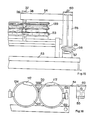
- the purpose of the device 9 for supporting and stabilizing the position of the internal concentrator shown in FIGS. 1B, 4 and 24 is to keep the core 78 of the concentrator in alignment with the axis of the tube blank 7.
- a support bar 106 is rigidly fixed to the frame 53 of the installation.
- To this bar 106 are fixed the upstream 8 and downstream support blades 16.
- Each support blade 8 and 16 is made of polyfluoroethylene, thin enough to pass through the slot 10 (see FIG. 24).
- the lower ends of the blades 8 and 16 are split into several portions 107, 108, 109 spaced apart in opposite directions so as to surround the tube 81 over at least a little more than half the circumference.
- the clamping between the blades 8 and 16 and the tube 81 is a friction clamping which allows the sliding of the tube 81 in upstream or downstream direction according to the movement imposed by the position control device 3.
- the friction clamping does not prevent , no longer the pivoting of the tube 81 although it opposes resistance to such pivoting.
- the curved screen 116 is surmounted by a sheet 117 covering the upper flange of a roller 23; it is fixed to an intermediate screen 118.
- the latter is fixed to the screen 110 by means of screws 119 engaged in a vertical buttonhole 120.
- the curved screen 116 is fixed to the intermediate screen 118 by means of a screw 121 engaged in a horizontal buttonhole 122.
- Other protections are copper plates 123 applied to the upper face of the rollers 23 which allow the elimination of heat by sprinkling the edges of the rollers 23 by means of a shower tube 124, the holes 125 of which are arranged along the parts 126 of the circumferences of the rollers 23 outside the welding zone.
- a brush 127 made of flexible material, for example polytetrafluoroethylene, follows the contour of the roller and completely wipes the shower water.
- the induction coil 18 is supplied with a current of 50,000 Hz, but is preferably chosen from the range of 30,000 to 90,000 Hz for tubes with an outside diameter of approximately 25mm.
Landscapes
- Engineering & Computer Science (AREA)
- Mechanical Engineering (AREA)
- General Induction Heating (AREA)
- Lining Or Joining Of Plastics Or The Like (AREA)
Abstract
Description
- La présente invention a pour objet une installation de soudage par induction pour la fabrication de tubes à des vitesses sensiblement plus élevées que celles obtenues jusqu'à présent. L'invention s'applique principalement aux tubes en acier inoxydables, mais des tubes en d'autres métaux peuvent être soudés aussi avec avantage dans l'installation suivant l'invention.
- Des installations de soudage par induction pour la fabrication de tubes sont en soi connues et décrites, par exemple dans les brevets US 1 365 198 et US 2 687 464. Elles comprennent des moyens pour transporter une ébauche de tube à souder à travers une bobine d'induction reliée à un générateur de courant alternatif. Les courants induits engendrés dans l'ébauche de tube servent à l'échauffement des bords jusqu' à une température suffisante au soudage de ceux-ci sous l'effet d'une force qui les presse l'un contre l'autre, exercée par des galets de forgeage situés en aval de la bobine d'induction.
- Suivant l'invention, une installation de soudage par induction pour la fabrication de tubes comprenant une bobine d'induction entourant une ébauche de tube dont les bords déterminent une fente qui se rétrécit vers l'aval, des galets de forgeage situés en aval de la bobine d'induction appliquant l'un contre l'autre les bords chauffés de l'ébauche à l'endroit d'un point de soudage situé à proximité d'un plan reliant les axes des galets de forgeage et un concentrateur interne disposé à l'intérieur de l'ébauche est caractérisée en ce que le concentrateur interne comprend un empilage de tôles magnétisables orientées parallèlement au diamètre du tube passant par la fente de l'ébauche et de longueur plus grande que la distance entre l'extrémité amont de la bobine d'induction et les axes des galets de forgeage.
- L'invention est expliquée ci-dessous par rapport à un exemple d' une forme d'exécution en se référant au dessin annexé.
- Les figutes IA et IB sont les deux parties d'une seule et même vue en élévation d'une installation de soudage de tubes suivant l'invention. Les figures 2 et 3 sont des sections d'une ébauche de tube avant soudage. La figure 4.est une vue en plan et la figure 5 une vue en coupe de l'installation de soudage de tubes montrée aux figures 1 et 2 au voisinage de la bobine d'induction. La figure 6 montre les amenées de courant à la bobine d'induction. Les figures 7, 8 et 8A sont respectivement une coupe selon X-X et d'autres vues de la disposition représentée à la figure 6. Les figures 9 et 10 sont une vue en coupe et une vue en plan d'un concentrateur externe. La figure Il représente un dispositif de montage du concentrateur externe. Les figures 12, 13 et 14 sont des vues en coupe, en plan et en élévation du concentrateur externe. La figure 15 est une vue en élévation et la figure 16 une vue en plan d'un dispositif support du concentrateur externe. Les figures 17, 18, 19 et 20 sont une vue en coupe longitudinale et plusieurs vues en coupes transversales d'un concentrateur interne. Les figures 21, 22, 23 et 24 sont des vues d'un dispositif support et de commande de la position du concentrateur interne. Les figures 25 et 26 sont deux vues d'un dispositif de refroidissement et de protection des-galets de forgeage de l'installation.
- Les dessins ne montrent pas des détails d'isolation de montage et de liaison qui sont évidents pour l'expert et ne constituent pas des caractéristiques de l'invention.
- Les figures 1A et 1B sont destinées à être assemblées le long des lignes à droite de la figure 1A et à gauche de la figure 1B pour constituer une seule figure. Côté amont, à droite, une bobine alimentaire, non représentée, fournit un ruban 1 de tôle en acier inoxydable, Cette tôle traverse d'abord une partie 2 de l'installation où se trouvent divers galets de formage non décrits en détail, parce qu'ils ne font pas partie de l'invention. Ensuite, plus vers l'aval, se trouve un dispositif support et de commande 3 de la position d'un concentrateur interne décrit plus en détail ultérieurement. Au delà du dispositif 3 se trouvent deux paires de galets de formage 4 et 6. A la sortie des galets de formage 6,la tôle présente la forme d'une ébauche de tube 7. Un peu plus loin, une lame de support amont 8 d'un dispositif de support et de stabilisation 9 d'un concentrateur interne passe à travers une fente 10 entre les bords de l'ébauche de tube 7 (voir figure 2). L' ébauche de tube traverse ensuite deux paires de galets de formage Il et 12 entre lesquels un galet 13 à flasques 14 métalliques assure la position correcte de l'ébauche 7 et règle la largeur de la fente 10 (figure 3). Entre les flasques métalliques 14 du galet 13 un corps isolant 15 est disposé pour éviter la création d'un chemin conducteur à travers les flasques 14 entre les bords de l'ébauche de tube 7 de part et d'autre de la fente 10. Immédiatement après le galet 13 une lame de support 16 du dispositif support 9 du concentrateur interne passe à travers la fente 10 à la hauteur des galets de formage 12.
- Un peu plus loin, en direction aval, un écran en matériau conducteur d'électricité 17 percé d'un trou légèrement plus grand que la section de l'ébauche de tube 7 est disposé à proximité et en amont d' une bobine d'induction 18 décrite en détail ultérieurement. La bobine d'induction engendre des courants de Foucault dans l'ébauche de'tube 7. Ces courants chauffent les bords de la fente 10 et les portent à la température de soudage.
- Un autre écran 19 en matériau conducteur d'électricité est disposé en aval de la bobine d'induction 18. Au delà de cet écran 19 est disposé un concentrateur externe 20 décrit en détail ultérieurement. Le concentrateur externe 20 sert de support à un système de tubes 21 d' alimentation de gaz inerte qui est soufflé sur l'ébauche de tube 7 entre la bobine d'induction 18 et une paire de galets de forgeage 23. Certains des tubes 21 véhiculent un réfrigérant pour le concentrateur externe 20,par exemple de l'eau de refroidissement.
- Les galets de forgeage 23 pressent l'un contre l'autre les bords de l'ébauche de tube 7 en un point voisin à un plan 24 passant par les axes des galets 23. En aval des galets de forgeage 23, des galets de serrage 25 et 26 (figure 4) sont prévus. Ils ont pour effet de stabiliser convenablement l'ébauche de tube 7 dans la région amont, c'est-à-dire à l'endroit des galets de forgeage 23. Ensuite l'installation est classique et comprend des outils de grattage 27 pour enlever la surépaisseur du cordon de soudure, et d'autres galets 28, 29, 30 qui conduisent le tube fini ve-s une station de découpage non représentée.
- Les composants de l'installation qui sont responsables des avantages de l'invention et notamment du fait de permettre le soudage de tubes en acier inoxydable à des vitesses particulièrement élevées sont le concentrateur interne, le concentrateur externe, la bobine d'induction, les dispositifs de support et de commande de position du concentrateur interne, les dispositifs de protection des galets de forgeage et le système de stabilisation de l'ébauche de tube au cours de son défilement à travers l'installation de soudage.
- Le concentrateur externe 20 montré aux figures 1A, 4, 5 et 9 à 14 est une pièce métallique, non magnétique, mais cnnductrice d'électricité, par exemple en cuivre. Il est disposé au dessus de la fente 10 de l'ébauche de tube 7 entre la bobine d'induction 18 et le plan 24 passant par les axes des galets de forgeage 23. La forme du concentrateur externe est montrée aux figures 9,10 et 12. Le concentrateur 20 est constitué par un corps cintré 31 qui s'étend le long du contour de l'ébauche de tube 7 de part et d'autre d'une région supérieure centrale 32 recouvrant la fente 10. Le plan de symétrie du concentrateur externe 20 passe par l'axe longitudinal de l'ébauche de tube 7. A 1' extrémité amont du concentrateur externe (à droite aux figures 9 et 10) le coprs 31 enveloppe l'ébauche de tube sur un angle mesurant environ 240°(figure 12). Cette extension angulaire est maintenue jusqu'à un point 33 en aval de l'extrémité amont. A partir du point 33 l'extension angulaire du corps 31 diminue de sorte que son bord suit des courbes 34 et 35 montrées en plan aux figures 4 et 10 et en élévation à la figure 9. Comme on peut le voir sur la figure 4 le concentrateur externe 20 occupe un espace en forme de coin entre les galets de forgeage 23 et présente des parties appelées jupes à bords courbes qui s'étendent latéralement à partir de la région centrale 32.
- Le concentrateur externe 20 supporte, ou inversement est supporté par, un ensemble de quatre tubes 36, 37, 38 et 39 solidarisés avec lui à la partie supérieure. Le tube 36 se termine par une partie horizontale fixée à la région supérieure centrale 32. Cette partie horizontale comprend une série d'ouvertures 40 qui communiquent avec des ouvertures 41 dans le concentrateur 20. Ces ouvertures 40 et 41 permettent de souffler un gaz inerte, par exemple de l'argon dans l'espace sous le concentrateur externe et d'écarter l'oxygène de l'air de la zone de soudage. Un apport supplémentaire d'argon est introduit par le tube 37 qui se termine en un bec de soufflage en matériau isolant électrique 42 à l'extrémité aval 43 du concentrateur. Les tubes 38 et 39 servent à véhiculer un fluide réfrigérant, par exemple de l'eau qui arrose les jupes du concentrateur externe. Les tubes 36 à 39 sont de préférence en cuivre et réunies en un seul paquet par brasure. Un agencement supplémentaire du concentrateur externe est constitué par une paire de volants 44 et 45 montrés à la figure 12. Les volants 44 et 45 sont fixés aux jupes par des vis 46 et des plaques courbes de serrage 47 et 48 et rentrent à l'intérieur des jupes pour s'appliquer élastiquement sur l'ébauche de tube 7. Ainsi, les volants 44 et 45 empêchent l'argon de s'échapper de l'espace en dessous du concentrateur et l'obligent de lécher les bords de la fente 10.
- De l'argon supplémentaire est amené en outre par des tubes 49, 50 et 51 disposés en amont et à proximité immédiate de l'étranglement entre les galets de forgeage 23 afin d'exclure l'oxygène de la zone de soudage. Les tubes 49, 50 et 51 réalisés en polytétrafluoréthylène par exemple, sont solidarisés avec le paquet de tubes 36, 37, 38 et 39 par exemple au moyen d'un collier de serrage 52 (figure 13).
- Le concentrateur externe 20 est supporté à partir d'un bâti 53 de l'installation par l'intermédiaire d'un dispositif de positionnement permettant des ajustements fins dans les trois dimensions x, y, z. Pour ce faire, le paquet de tubes 36 à 39 est fixé à une barre 54 (figures 5, 11, 15 et 16) monté sur une colonne 55. La colonne 55 est solidaire d'un coulisseau 56, lui-même relié à un coulisseau 57. Le mouvement (direction x) entre le coulisseau 56 et son support 57 est commandé par une vis mère 58. Le mouvement (direction y) du coulisseau 57 par rapport au bâti 53 est perpendiculaire au mouvmenet entre les éléments 56 et 57 et est également commandé par une vis mère 59. Le mouvement- entre la barre 54 et la colonne 55 (direction verticale z) est également commandé par une vis mère 60.
- La bobine d'induction 18 comprend cinq spires d'un tube à section carrée parcouru par de l'eau de refroidisssement. Les spires de la bobine 18 sont enroulées sur un support isolant 61, par exemple en polytétrafluoréthylène dont l'alésage est légèrement plus grand que la section de l'ébauche de tube 7. Les spires de la bobine 18 sont disposés dans des plans verticaux perpendiculaires à l'axe de l'ébauche 7. Elles sont reliées entr'elles et à l'alimentation par des portions de conducteur disposées du côté opposé à la fente (10) de l'êbauche(Fig.8B).
- La bobine 18 doit être maintenue rigidement à sa place par rapport à l'axe longitudinal de l'ébauche de tube 7 et le plan 24 passant par les axes des galets de forgeage. Un exemple d'une telle fixation est montré aux figures 6 à 8. Des connexions 62 et 63 sont serrées par des rondelles 64 et 65 sur des plaques conductrices 66 et 67 séparées par une couche isolante 68,par exemple en polytétrafluoréthylène (figure 7) Grâce à un tel agencement, l'énergie électrique nécessaire est amenée à pied d'oeuvre en quantité suffisante. Les connexions 62 et 63 s'étendent au delà de leur point de fixation à l'endroit des rondelles 64 et 65 pour être reliées à des tubes d'eau de refroidissement non représentés. Afin d'assurer une raideur et stabilité latérale suffisante aux plaques conductrices 66 et 67, ces dernières sont doublées de plaques 69 et 70,par exemple en plexiglas,reliées entr'elles par des tire-fond 71. Une barre de stabilisation 72 entre l'extrémité du support de bobine et le bâti 53 procure une stabilité supplémentaire pour la bobine d'induction 18.
- PoiL-faciliter l'ajustement de la position de la bobine 18 par rapport à l'axe longitudinal de l'ébauche de tube 7, l'alimentation électrique est montée sur un chariot 73 déplaçable sur des rails 74 au moyen de roues 75. La barre de stabilisation 72 comprend des boutonnières 76(figure 6) dans lesquelles passent des boulons 77 serrés dès que la bonne position de la bobine 18 est réglée par le déplacement du chariot 73 sur les rails 74.
- Le concentrateur interne est représenté aux figures 5 et 17 à 20. Il se trouve à l'intérieur de l'ébauche de tube 7. Le concentrateur interne comprend un noyau en un empilage de bandes de tôle 78 en matériau magnétisable telles qu'utilisées pour des transformateurs. Les plans des tôles doivent être verticaux, c'est-à-dire être parallèles à un plan passant par l'axe longitudinal de l'ébauche 7 et la fente 10. L'extrémité aval 79 du noyau 78 du concentrateur est ajustée à une position déterminée en amont du plan 24 passant par les axes des galets de forgeage 23. L'extrémité amont 80 du noyau 78 du concentrateur se trouve en amont de la bobine d'induction 18 d'une longueur au moins égale à la longueur de la bobine 18.
- Le noyau 78 du concentrateur est logé à serrage dans un tube 81 en matériau isolant électrique par exemple en polytétrafluoréthylène. A l'extrémité aval 82 du tube 81 un dispositif de centrage tel que montré à la figure 19 est prévu, constitué par des tétons de guidage 83. Un fluide réfrigérant est véhiculé à travers l'ébauche de tube 7 d'une part dans l'espace entre la surface intérieure de l'ébauche et la surface extérieure du tube 81 et d'autre part dans l'espace entre la surface intérieure du tube 81 et le noyau 78.
- En amont de l'extrémité 80 du concentrateur interne, le tube 81 est relié de manière non rotative, à l'aide d'un goujon 84 à un autre tube 85 qui peut être en un matériau conducteur d'électricité (figure 17)..Ensuite, à l'aide d'un raccord 86, le tube 85 est relié à un autre tube 87 faisant partie du dispositif support et de commande 3 de la position du concentrateur interne, déjà montré à la figure 1B. A un endroit déterminé en amont du noyau du concentrateur, un doigt 88/indicateur de pivotement du noyau est monté sur le tube 87.Cê doigt 88 (figure 20) est plus mince que la largeur de la fente 10 par laquel- le il passe. Il peut exécuter des mouvments de pivotement autour de l'axe longitudinal de l'ébauche 7 d'au moins 10° pour indiquer si le noyau tourne par rapport à la position imposée. Si le tube 87 est fermement maintenu à son extrémité amont dans le raccord 86 et si le doigt 88 se trouve à mi-chemin entre le noyau 78 et le raccord 87, 1' angle de rotation indiqué par le doigt 88 représente une fraction de l'angle de torsion du noyau 78, déterminée par les caractéristiques de torsion du noyau 78 et des tubes 81, 85 et 87.
- Le dispositif de commande 3 de la position du concentrateur interne montré à la figure IB a pour but d'une part de fixer la position exacte de l'extrémité aval 79 du noyau du concentrateur par rapport au plan 24 et d'autre part de permettre le retrait du noyau du concentrateur à une distance déterminée du plan 24 lors du démarrage de l'installation, ceci afin d'éviter des surchauffes de l'ébauche de tube 7 à proximité de la bobine 18 et du concentrateur externe 20 lors du démarrage.
- Selon les figures 21, 22 et 23, le tube 87 est fixé à un bras 89 au moyen de raccords 90 convenables. Le tube 87 est prolongé par un tube 91 vers un réservoir non représenté de fluide réfrigérant pour le concentrateur interne. Le bras 89 est supporté par une crémaillère 92 dans laquelle engrène un pignon 93. Le pignon 93 se trouve sur un arbre 94 d'une manivelle 95. Tous ces éléments sont montés sur une structure de support 96 solidaire du bâti 53. Un autre pignon 97 sur le même arbre 94 engrène avec une crémaillère 98 reliée par un bras 99 à une tige de piston 100 d'un vérin pneumatique ou hydraulique 101 également monté sur le support 96. Une tige filetée 102 prolonge la crémaillère 98 et est munie d'une rondelle d'arrêt 103 qui peut être verrouillée au moyen d'une vis de blocage 104. La tige 102 traverse librement une ouverture dans une traverse 105 solidaire de la structure support 96.
- En actionnant dans une première direction le vérin 101 par un dispositif de commande hydraulique ou pneumatique approprié, non repré- enté, la crémaillère 98 est déplacée vers la droite (figures 22 et 23) et le concentrateur interne est retiré dans une position amont (figure 21 à droite). En acitonnant le vérin 10 dans la direction opposée, la crémaillère 98 se déplace vers la gauche (figures 22 et 23) jusqu'à ce que la rondelle d'arrêt 103 bute sur la travers 105. La position de cette rondelle d'arrêt est ajustée de telle manière que le concentrateur interne s'arrête à une distance déterminée en amont du plan 24. La manivelle 95 permet de déplacer le concentrateur lors de l'ajustement de la position de la rondelle d'arrêt 103.
- Le dispositif 9 de support et de stabilisation de la position du concentrateur interne montré aux figures 1B, 4 et 24 a pour but de maintenir le noyau 78 du concentrateur dans l'alignement de l'axe de 1' ébauche de tube 7. Pour ce faire une barre de support 106 est fixée de manière rigide au bâti 53 de l'installation. A cette barre 106 sont fixées les lames de support amont 8 et aval 16. Chaque lame de support 8 et 16 est en polyfluoréthylène, suffisamment mince pour traverser la fente 10 (voir figure 24). Les extrémités inférieures des lames 8 et 16 sont fendues en plusieurs portions 107, 108, 109 écartées dans des directions opposées de manière à entourer le tube 81 sur au moins un peu plus que la moitié de la circonférence.
- Le serrage entre les lames 8 et 16 et le tube 81 est un serrage à friction qui permet le glissement du tube 81 en direction amont ou aval suivant le mouvement imposé par le dispositif de commande de position 3. Le serrage à friction n'mpêche pas, non plus le pivotement du tube 81 bien qu'il oppose une résistance à de tels pivotements.
- Pendant le fonctionnement de l'installation,un échauffement des galets de forgeage 23 a lieu. Cet échauffement doit être limité par des dispositifs de protection et des écrans tels que montrés aux figures 15, 16, 25 et 26. Juste en amont des galets de forgeage 23, entre ces galets et le concentrateur externe 20,des écrans 110 sont placés près des galets et fixés au bâti 53 au moyen de pattes 111. Les écrans 110 s'étendent jusqu'à une plaque 112 et sont pleins, sauf une ouverture rectangulaire 113. Des tubes 114 sont appliqués sur la face amont et raccordés à un réservoir de liquide réfrigérant au moyen de raccords 115 . Chaque écran 110 est complèté par un écran courbe 116 protégeant le flasque d'un galet 23. L'écran courbe 116 est surmonté d'une tôle 117 recouvrant le flasque supérieur d'un galet 23; il est fixé à un écran intermédiaire 118. Ce dernier est fixé à l'écran 110 au moyen de vis 119 engagées dans une boutonnière verticale 120. L' écran courbe 116 est fixé à l'écran intermédiaire 118 au moyen d'une vis 121 engagée dans une boutonnière horizontale 122. De cette manière l'écran courbe 116 peut être positionné facilement de manière précise à proximité immédiate du galet 23. D'autres protections sont des plaques en cuivre 123 appliquées sur la face supérieure des galets 23 qui permettent l'élimination de la chaleur grâce à un arrosage des bords des galets 23 au moyen d'un tube à douche 124 dont les treus 125 sont disposés le long des parties 126 des circonférences des galets 23 à l'extérieur de la zone de soudage. Pour éviter que du réfrigérant puisse perturber le soudage, un balai 127 en matériau flexible, par exemple en polytétrafluoréthylène, suit le contour du galet et essuie complètement l'eau de la douche.
- L'alimentation de la bobine d'induction 18 se fait par un courant de 50 000 hz, mais est choisie de préférence dans la gamme de 30 000 à 90 000 Hz pour les tubes d'un diamètre extérieur d'environ 25mm.
- Les résultats excellents obtenus par l'installation notamment lors du soudage de tubes en acier inoxydable semblent être dûs notamment à une concentration de champs électromagnétiques particulièrement favorable à proximité du point de soudage ainsi qu'à une excellente stabilisation géométrique de ce point de soudage. L'élément principal semble être le concentrateur interne et sa coopération avec le concentrateur externe.
Claims (14)
Applications Claiming Priority (2)
| Application Number | Priority Date | Filing Date | Title |
|---|---|---|---|
| US05/896,361 US4268736A (en) | 1978-04-13 | 1978-04-13 | Induction welding apparatus for manufacture of tubing |
| US896361 | 1986-08-13 |
Publications (2)
| Publication Number | Publication Date |
|---|---|
| EP0004989A1 true EP0004989A1 (fr) | 1979-10-31 |
| EP0004989B1 EP0004989B1 (fr) | 1981-09-23 |
Family
ID=25406073
Family Applications (1)
| Application Number | Title | Priority Date | Filing Date |
|---|---|---|---|
| EP79200165A Expired EP0004989B1 (fr) | 1978-04-13 | 1979-04-04 | Installation de soudage par induction pour la fabrication de tubes |
Country Status (6)
| Country | Link |
|---|---|
| US (1) | US4268736A (fr) |
| EP (1) | EP0004989B1 (fr) |
| JP (1) | JPS5510390A (fr) |
| BR (1) | BR7902275A (fr) |
| DE (1) | DE2960872D1 (fr) |
| ES (1) | ES479528A1 (fr) |
Cited By (4)
| Publication number | Priority date | Publication date | Assignee | Title |
|---|---|---|---|---|
| EP0034902A3 (fr) * | 1980-02-25 | 1981-11-25 | The Continental Group, Inc. | Appareil et méthode de soudage |
| EP0053769A1 (fr) * | 1980-11-28 | 1982-06-16 | Nippon Steel Corporation | Concentrateur de champ pour le soudage électrique par résistance de tubes |
| US4596913A (en) * | 1981-05-19 | 1986-06-24 | Nippon Steel Corporation | Impeder for electric resistance tube welding |
| WO2014071488A1 (fr) | 2012-11-12 | 2014-05-15 | Whirpool S.A. | Équipement de formation de tubes de raccordement |
Families Citing this family (11)
| Publication number | Priority date | Publication date | Assignee | Title |
|---|---|---|---|---|
| US4608471A (en) * | 1985-03-05 | 1986-08-26 | Allied Tube & Conduit Corporation | Impeder with aggregate ferromagnetic core |
| JP2003001325A (ja) * | 2001-06-20 | 2003-01-07 | Mitsubishi Shindoh Co Ltd | 電縫管のスクイズロール清掃機構 |
| US6875966B1 (en) | 2004-03-15 | 2005-04-05 | Nexicor Llc | Portable induction heating tool for soldering pipes |
| US7399264B2 (en) * | 2004-09-14 | 2008-07-15 | Mill Masters, Inc. | High frequency induction welding of austenitic stainless steel for pressure vessel tubing |
| DE102007054782A1 (de) * | 2007-11-16 | 2009-05-20 | Mtu Aero Engines Gmbh | Induktionsspule, Verfahren und Vorrichtung zur induktiven Erwärmung von metallischen Bauelementen |
| CN102405116A (zh) * | 2009-04-24 | 2012-04-04 | 阿里汉家用设备有限公司 | 一种低碳焊管及其制作方法 |
| BR112012005765A2 (pt) * | 2009-09-16 | 2021-01-05 | Nippon Steel Corporation | Aparelho de solda de tubo soldado com resistência elétrica |
| EP2478989A4 (fr) * | 2009-09-16 | 2017-06-21 | Nippon Steel & Sumitomo Metal Corporation | Dispositif de soudage permettant de fabriquer un tube soudé par résistance électrique |
| AU2010363647B2 (en) * | 2010-11-11 | 2015-11-26 | Halliburton Energy Services, Inc. | Milling well casing using electromagnetic pulse |
| US10343835B2 (en) * | 2013-07-25 | 2019-07-09 | Bemis Company, Inc. | Easy-open self-venting microwavable tray and overwrap |
| ES2646991B1 (es) | 2016-06-17 | 2018-09-27 | Gh Electrotermia, S.A. | Proceso de soldadura por inducción de tubos con diámetro variable y dispositivo para llevarlo a cabo |
Citations (6)
| Publication number | Priority date | Publication date | Assignee | Title |
|---|---|---|---|---|
| FR715078A (fr) * | 1930-06-18 | 1931-11-25 | Youngstown Sheet And Tube Co | Perfectionnements aux appareils à souder |
| FR716232A (fr) * | 1930-07-22 | 1931-12-17 | Youngstown Sheet And Tube Co | Perfectionnements apportés aux procédés et aux appareils de soudure |
| DE1142671B (de) * | 1960-10-15 | 1963-01-24 | Demag Ag | Vorrichtung zum induktiven Aneinanderschweissen der Kanten eines zu einem Rohr gebogenen Bandes |
| US3270176A (en) * | 1964-08-18 | 1966-08-30 | Continental Can Co | Impeder device for improving radio-frequency induction welding |
| US3397295A (en) * | 1964-02-28 | 1968-08-13 | Tube Prod Ltd | Induction tube welding apparatus |
| BE836000A (fr) * | 1975-11-27 | 1976-05-28 | Elphiac Sa | Installation de soudage de tubes |
Family Cites Families (13)
| Publication number | Priority date | Publication date | Assignee | Title |
|---|---|---|---|---|
| US1365198A (en) * | 1919-03-24 | 1921-01-11 | Frank L Sessions | Method of and apparatus for electrically welding tubing |
| FR676923A (fr) * | 1928-08-07 | 1930-02-28 | Youngstown Sheet And Tube Co | Perfectionnements aux procédés de soudure |
| US1932423A (en) * | 1929-08-22 | 1933-10-31 | Frank L Sessions | Apparatus for electric induction welding and heating |
| US1967129A (en) * | 1930-07-22 | 1934-07-17 | Youngstown Sheet And Tube Co | Welding |
| US2020276A (en) * | 1931-04-27 | 1935-11-05 | Smith Corp A O | Electric heating and welding |
| US2632079A (en) * | 1950-11-30 | 1953-03-17 | Ohio Crankshaft Co | Means and method for electric seam welding |
| US2687465A (en) * | 1951-01-11 | 1954-08-24 | Thomas J Crawford | High-frequency induction tube welding |
| US2687464A (en) * | 1951-01-11 | 1954-08-24 | Thomas J Crawford | High-frequency induction tube welding |
| US3037105A (en) * | 1961-09-25 | 1962-05-29 | American Mach & Foundry | Methods and apparatus for the induction welding of tubing |
| CH527016A (de) * | 1970-03-13 | 1972-08-31 | Siemens Ag | Vorrichtung zum induktiven Längs- oder Spiralnahtschweissen von Metallrohren |
| US3689725A (en) * | 1970-08-14 | 1972-09-05 | Republic Steel Corp | Apparatus for high speed welding of stainless steel tube with high velocity gas |
| US3648005A (en) * | 1970-08-28 | 1972-03-07 | Amf Inc | Induction tube welding with improved current path |
| US3733453A (en) * | 1972-02-18 | 1973-05-15 | Olin Corp | High frequency weld box |
-
1978
- 1978-04-13 US US05/896,361 patent/US4268736A/en not_active Expired - Lifetime
-
1979
- 1979-04-04 DE DE7979200165T patent/DE2960872D1/de not_active Expired
- 1979-04-04 EP EP79200165A patent/EP0004989B1/fr not_active Expired
- 1979-04-11 ES ES479528A patent/ES479528A1/es not_active Expired
- 1979-04-11 BR BR7902275A patent/BR7902275A/pt unknown
- 1979-04-13 JP JP4520679A patent/JPS5510390A/ja active Pending
Patent Citations (6)
| Publication number | Priority date | Publication date | Assignee | Title |
|---|---|---|---|---|
| FR715078A (fr) * | 1930-06-18 | 1931-11-25 | Youngstown Sheet And Tube Co | Perfectionnements aux appareils à souder |
| FR716232A (fr) * | 1930-07-22 | 1931-12-17 | Youngstown Sheet And Tube Co | Perfectionnements apportés aux procédés et aux appareils de soudure |
| DE1142671B (de) * | 1960-10-15 | 1963-01-24 | Demag Ag | Vorrichtung zum induktiven Aneinanderschweissen der Kanten eines zu einem Rohr gebogenen Bandes |
| US3397295A (en) * | 1964-02-28 | 1968-08-13 | Tube Prod Ltd | Induction tube welding apparatus |
| US3270176A (en) * | 1964-08-18 | 1966-08-30 | Continental Can Co | Impeder device for improving radio-frequency induction welding |
| BE836000A (fr) * | 1975-11-27 | 1976-05-28 | Elphiac Sa | Installation de soudage de tubes |
Cited By (4)
| Publication number | Priority date | Publication date | Assignee | Title |
|---|---|---|---|---|
| EP0034902A3 (fr) * | 1980-02-25 | 1981-11-25 | The Continental Group, Inc. | Appareil et méthode de soudage |
| EP0053769A1 (fr) * | 1980-11-28 | 1982-06-16 | Nippon Steel Corporation | Concentrateur de champ pour le soudage électrique par résistance de tubes |
| US4596913A (en) * | 1981-05-19 | 1986-06-24 | Nippon Steel Corporation | Impeder for electric resistance tube welding |
| WO2014071488A1 (fr) | 2012-11-12 | 2014-05-15 | Whirpool S.A. | Équipement de formation de tubes de raccordement |
Also Published As
| Publication number | Publication date |
|---|---|
| BR7902275A (pt) | 1979-12-11 |
| DE2960872D1 (en) | 1981-12-10 |
| EP0004989B1 (fr) | 1981-09-23 |
| ES479528A1 (es) | 1980-01-01 |
| JPS5510390A (en) | 1980-01-24 |
| US4268736A (en) | 1981-05-19 |
Similar Documents
| Publication | Publication Date | Title |
|---|---|---|
| EP0004989A1 (fr) | Installation de soudage par induction pour la fabrication de tubes | |
| DE69017058T2 (de) | Elektromagnetisches Induktionsheizgerät. | |
| EP0170556B1 (fr) | Dispositif à induction électromagnétique pour le chauffage d'éléments métalliques | |
| US4969255A (en) | Apparatus for producing heat exchanger tubes | |
| FR2514280A1 (fr) | Procede de soudage a l'arc a faible ecartement entre les pieces a souder et appareil permettant d'appliquer ledit procede | |
| FR2808163A1 (fr) | Dispositif de chauffage par induction a flux transverse a circuit magnetique de largeur variable | |
| FR2530517A1 (fr) | Appareil de serrage de pieces a souder par un faisceau laser, tablette formee par soudage de pieces, et procede de fabrication d'une telle plaquette | |
| FR2701880A1 (fr) | Appareil et procédé pour un soudage en intervalle étroit. | |
| EP1458514B1 (fr) | Dispositif de soudage pour materiau d'emballage | |
| EP0270586B1 (fr) | Dispositif de soudage d'un embout sur un film thermoplastique | |
| CH424413A (fr) | Procédé pour joindre deux bandes, machine pour la mise en oeuvre du procédé et bande obtenue | |
| CH620849A5 (fr) | ||
| BE429465A (fr) | Machine à souder par l'électricité | |
| EP0403327A1 (fr) | Procédé et dispositif de remplacement d'une canne chauffante d'un pressuriseur d'un réacteur nucléaire à eau sous pression | |
| FR2634416A1 (fr) | Assemblage oscillant a fil metallique de soudage pour thermosoudage d'un film thermoplastique et machine a empaqueter horizontale pour empaqueter des objets dans un film thermoplastique comportant un tel assemblage oscillant | |
| CA2130446A1 (fr) | Module inducteur pour un moteur electrique lineaire asynchrone et son procede de fabrication | |
| EP0693344B1 (fr) | Procédé et ligne de réparation d'un défaut de fermeture d'un tube métallique contenant au moins une fibre optique de transmission | |
| FR2662231A1 (fr) | Banc d'assemblage d'ailes et d'ames pour la fabrication de profiles notamment de profiles en i. | |
| CH341927A (fr) | Machine pour le soudage automatique à l'arc électrique | |
| FR3129862A1 (fr) | Dispositif de protection pour le soudage à l’arc de goujons ou similaires à une pièce support par fusion forgeage et appareil de soudage le comprenant | |
| KR200489822Y1 (ko) | 수동 티그용접 용접봉 송급 및 연결장치 | |
| BE655762A (fr) | ||
| EP0209450B1 (fr) | Machine pour former, dans une tôle, des ondes parallèles et pour souder chacune de ces ondes à ses extrémités longitudinales | |
| FR2471833A1 (fr) | Dispositif d'assemblage par soudage ou de placage de pieces de section circulaire | |
| JPS6115789B2 (fr) |
Legal Events
| Date | Code | Title | Description |
|---|---|---|---|
| PUAI | Public reference made under article 153(3) epc to a published international application that has entered the european phase |
Free format text: ORIGINAL CODE: 0009012 |
|
| AK | Designated contracting states |
Designated state(s): BE CH DE FR GB IT LU NL SE |
|
| 17P | Request for examination filed | ||
| GRAA | (expected) grant |
Free format text: ORIGINAL CODE: 0009210 |
|
| AK | Designated contracting states |
Designated state(s): BE CH DE FR GB IT LU NL SE |
|
| PG25 | Lapsed in a contracting state [announced via postgrant information from national office to epo] |
Ref country code: SE Effective date: 19810923 Ref country code: NL Effective date: 19810923 Ref country code: IT Free format text: LAPSE BECAUSE OF FAILURE TO SUBMIT A TRANSLATION OF THE DESCRIPTION OR TO PAY THE FEE WITHIN THE PRESCRIBED TIME-LIMIT;WARNING: LAPSES OF ITALIAN PATENTS WITH EFFECTIVE DATE BEFORE 2007 MAY HAVE OCCURRED AT ANY TIME BEFORE 2007. THE CORRECT EFFECTIVE DATE MAY BE DIFFERENT FROM THE ONE RECORDED. Effective date: 19810923 |
|
| REF | Corresponds to: |
Ref document number: 2960872 Country of ref document: DE Date of ref document: 19811210 |
|
| NLV1 | Nl: lapsed or annulled due to failure to fulfill the requirements of art. 29p and 29m of the patents act | ||
| PG25 | Lapsed in a contracting state [announced via postgrant information from national office to epo] |
Ref country code: BE Effective date: 19820404 |
|
| PG25 | Lapsed in a contracting state [announced via postgrant information from national office to epo] |
Ref country code: LU Free format text: LAPSE BECAUSE OF NON-PAYMENT OF DUE FEES Effective date: 19820430 Ref country code: CH Effective date: 19820430 |
|
| REG | Reference to a national code |
Ref country code: CH Ref legal event code: PL |
|
| PG25 | Lapsed in a contracting state [announced via postgrant information from national office to epo] |
Ref country code: FR Free format text: LAPSE BECAUSE OF NON-PAYMENT OF DUE FEES Effective date: 19830131 |
|
| PG25 | Lapsed in a contracting state [announced via postgrant information from national office to epo] |
Ref country code: DE Effective date: 19830301 |
|
| REG | Reference to a national code |
Ref country code: FR Ref legal event code: ST |
|
| GBPC | Gb: european patent ceased through non-payment of renewal fee | ||
| PG25 | Lapsed in a contracting state [announced via postgrant information from national office to epo] |
Ref country code: GB Effective date: 19881117 |
|
| PLBE | No opposition filed within time limit |
Free format text: ORIGINAL CODE: 0009261 |
|
| STAA | Information on the status of an ep patent application or granted ep patent |
Free format text: STATUS: NO OPPOSITION FILED WITHIN TIME LIMIT |