EP0004594A1 - Sidewall for the loading space of a truck - Google Patents
Sidewall for the loading space of a truck Download PDFInfo
- Publication number
- EP0004594A1 EP0004594A1 EP79100846A EP79100846A EP0004594A1 EP 0004594 A1 EP0004594 A1 EP 0004594A1 EP 79100846 A EP79100846 A EP 79100846A EP 79100846 A EP79100846 A EP 79100846A EP 0004594 A1 EP0004594 A1 EP 0004594A1
- Authority
- EP
- European Patent Office
- Prior art keywords
- wall
- post
- channel
- side wall
- lifting
- Prior art date
- Legal status (The legal status is an assumption and is not a legal conclusion. Google has not performed a legal analysis and makes no representation as to the accuracy of the status listed.)
- Granted
Links
Images


Classifications
-
- B—PERFORMING OPERATIONS; TRANSPORTING
- B60—VEHICLES IN GENERAL
- B60J—WINDOWS, WINDSCREENS, NON-FIXED ROOFS, DOORS, OR SIMILAR DEVICES FOR VEHICLES; REMOVABLE EXTERNAL PROTECTIVE COVERINGS SPECIALLY ADAPTED FOR VEHICLES
- B60J5/00—Doors
- B60J5/04—Doors arranged at the vehicle sides
- B60J5/0497—Doors arranged at the vehicle sides for load transporting vehicles or public transport, e.g. lorries, trucks, buses
- B60J5/0498—Doors arranged at the vehicle sides for load transporting vehicles or public transport, e.g. lorries, trucks, buses with rigid panels pivoting about a horizontal axis
Definitions
- the invention relates to a side wall for box bodies of trucks, consisting of a lower folding wall and an upper lifting wall coupled therewith, which is mounted between two posts lying in the side wall plane.
- the posts each have a rectangular profile and do not protrude from the inside or outside of the side wall.
- Ropes run from the folding wall to the coupling elements of the lifting wall, each of which is arranged in a channel which is provided on each post against the side wall, has the post width and in which the rope pulleys are also provided.
- each post In a known side wall for box bodies of trucks of the aforementioned type (DT-Gbm 77 07 180) is each post.
- an arm (handlebar) is assigned, which is articulated at the top of the post and at the bottom near the lower edge of the lifting wall.
- Under the roof rails are attached, in which rollers attached to the upper edge of the lifting wall are guided.
- ropes are provided for each post, which emerge from the post near the roof, run to the middle of the box structure, are deflected there and fastened to the upper edge of the lifting wall. In the area of the post, the ropes and the rope guide elements remain inaccessible even when the side wall is open, since they are housed in a closed rectangular profile.
- a side wall for box bodies of trucks is known (DT-PS 23 58 186), in which the post-side ropes are each fastened with the upper end of the rope to a rotating segment, which is approximately half the height the lifting wall is rotatably attached to the post.
- An arm is attached to the rotating segment, the free end of which is articulated in the region of the lower edge of the lifting wall and which is directed vertically downward when the side wall is closed.
- the rope lies on the rotating segment at an angle of approximately 1 80 0 .
- the object of the invention is to be seen in designing a side wall for box bodies of trucks of the type mentioned at the outset in such a way that the channels formed by the posts are accessible for the purpose of servicing the cables and the coupling and locking elements.
- the rope and fastening and deflecting elements are freely accessible in the region of the folding wall and in the region of the lifting wall, for example on the channel-shaped part of the post. on the bar of the wall part.
- the invention further relates in particular to specially suitable coupling elements.
- the maximum loading width extends between the two rear posts up to the height of the rotating segments, which are arranged at least in the amount of half the lifting wall, or even higher if the lifting wall is guided over the roof when opening.
- the rotating segments are very high in the apex area between the roof and the lifting wall. Because only one rotating segment is required for each side wall in these versions, it is possible to arrange this on the front post so that the maximum loading width over the entire height of the box body is available between the posts. The same also applies to the embodiment according to claim 5, where only elements are required for coupling and guiding the ropes which are accommodated in the channel and do not protrude inside or outside.
- Locking elements for the wall parts are largely accessible for maintenance and repair and do not affect the loading width between the posts.
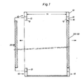
- the box structure shown in Fig. 1 is completed on each long side by a side wall 20/30 that can be opened.
- Each side wall is arranged between two posts, a front post and a rear post.
- a front post, a rear post and a middle post are provided on each long side and two side walls in between.
- a rear wall, not shown, is provided between the two rear posts and can also be opened.
- a usable width 14 is available for loading from the rear.
- the useful width 14 is the same as the clear width between the closed side walls.
- Each post 10 has a rectangular cross section of the same width as the side wall 20/30. With each post 10 is a channel-shaped part 12 in connection, arranged towards the side wall and open to the outside. A channel 13 is formed by the channel-shaped part, which is accessible from the outside when the side wall is open and is covered by a strip 16 of the side wall when the side wall is closed.
- the clear inside width of the box structure between the side walls and between the posts is only approx. 8 cm less than the prescribed maximum outside width.
- each arm consists of a folding wall 20 at the bottom and a lifting wall 30 at the top.
- the folding wall is fastened at the bottom with hinges 2 1 that can be folded down.
- An arm 35 is provided on the post side for holding and guiding the lifting wall 30, which is in a vertical position when the lifting wall is closed (dashed version) and is received by the channel 13.
- the arm is continued at one end in the form of a rotating segment 34.
- the rotary segment extends over an angle of about 180 0 and each is hinged pole side.
- each arm is connected to the lifting wall 30 in the lower region thereof by means of a joint 31.
- a rope 24 is provided for coupling the folding wall to the lifting wall.
- the arms 35 When the side wall is closed, the arms 35 are directed vertically downward, each being in the associated channels 13, which are covered by the strips 16 of the folding wall or the lifting wall.
- the rope lies over an angle of over 180 ° on the respective rotating segment.
- a roof-side opening 37 is covered by a roof connection part 31, which is attached at right angles to the upper edge of the lifting wall 30.
- the folding wall 20 When opening, the folding wall 20 is folded down. The two ropes are pulled down, the rotating segments 34 are rotated, the arms are pivoted outwards and the lifting wall 30 is raised. Rollers 32 attached to the roof connection 31 are guided in rails 39 which are attached to the roof.
- the folding wall 20 hangs vertically while the lifting wall is above the roof in a position parallel to the roof, as shown in phantom. In the floor plan, the lifting wall does not protrude laterally above the box body.
- the arms 35 When the side wall is open, the arms 35 are in the area of the opening 37 and are slightly inclined towards the middle of the structure.
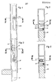
- the cable fastening 22 in the area of the folding wall is fastened to the bar 16 of the same, as can be seen from FIG. 3.
- the post-side roller 23 is attached to a wall of the groove-shaped part 12 of the post (FIG. 6).
- One leg of this channel-shaped part 12 lies on a sealing strip 25 which is attached to the strip 16 of the folding wall.
- FIGS. 4 and 5 How the hinge 33 is formed, through which the arm 35 is connected to the lifting wall, can be seen from FIGS. 4 and 5.
- a hinge pin 33a is fastened, which is received by an elongated hole of a tab 33b, which is fastened to the bar 16 of the lifting wall.
- an intermediate wall 38 can be articulated on the lower edge of the lifting wall.
- the wall parts are locked together when the side wall is closed.
- the locking elements can also be accommodated in the channel 13.
- the arms From the closed position of the side wall to the open position, the arms perform pivoting of 190 ° to 200 0th
- the rotating segments are each connected to a spring, not shown. These springs are tensioned in the open position. If the folding wall is raised when closing and the ropes are loosened as a result, the springs come into effect and initiate the flow movement of the lifting wall. The spring force lasts until the lifting wall moved by itself by its own weight. The folding wall is raised.
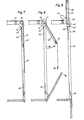
- a solid folding wall is provided in the side wall according to FIGS. 7 to 9, while the lifting wall 40, like the roof itself, is designed as a frame and covered with fabric 41.
- the closed side wall FIG. 7
- closure elements 42 are provided on the lower edge thereof.
- the lifting wall 40 is directly connected at the top to a continuous torsionally rigid tube 44 which is rotatably mounted on the post side at each end.
- a rope 46 is provided on this side wall, which is located either in the area of the front or the rear post. This rope is inserted at the bottom into the channel of the post and comes out of the channel at the top via a roller 45, where it is placed on a rotating segment 43 which is firmly connected to the tube 44.
- the axis of rotation of the rotating segment and the tube lies approximately in the angular area of the side wall-roof.
- the closing movement is initiated by a spring, not shown, connected to the rotating segment.
- the side wall 10-12 consists of solid wall parts, namely a bottom hinged folding wall, a lifting wall 50, which is attached to joints 50a at the top in the area of the roof and an intermediate wall 51, which is hinged to the lifting wall.
- a torsionally rigid tube 53 is rotatably mounted on the post side about a longitudinal axis over the entire length of the side wall.
- several pairs of links 54 are provided over the length. Of these, one handlebar is firmly attached to the tube 53, while the other is articulated on the inside of the lifting wall 50.
- a rope is provided which, as in the exemplary embodiments already described, is guided in the channel 13 from bottom to top and is deflected at the top via a roller onto the rotating segment 52.
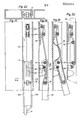
- the wall parts are locked by means of a drive bolt 58.
- the drive bolt is located in channel 13.
- An eccentric lock 55 with an actuating lever is provided in the post for its actuation.
- the connection between the eccentric and the drive bolt is via a rod 56 and a Cross piece 57 made.
- the side wall according to the fourth exemplary embodiment according to FIGS. 14 to 16 consists of a plate-shaped folding wall and also a plate-shaped lifting wall 60.
- the lifting wall is connected in the lower region at the front and rear via an arm 70 to the respective post, with a hinge pin 71 connecting the Armes with the post.
- Above the lifting wall is articulated with scales 61, which are guided on rails attached under the roof.
- Two cables 62 are provided for coupling the folding wall to the lifting wall. They are each guided upward in the channel of the post, and deflected downward in the upper region via a deflection roller 63 on the post side.
- the rope is tensioned in each case on a post-side tensioning roller 64, it extends from there over a deflection roller 72 attached to the arm and ends on a post-side rope fastening 65.
- a deflection roller 72 attached to the arm and ends on a post-side rope fastening 65.
- the two ropes are pulled downwards.
- the two ends of the rope sections each engage the roller 72 of the arm and pivot it up to a vertical position according to FIG. 16.
- the upper edge of the folding wall is guided through the carriage 6 1 to the center of the box structure.
- the closing movement is initiated by springs ge with open side wall - are stretched and exert on the arms forces.
- FIGS. 18 to 22 Details of the coupling elements of a side wall according to FIGS. 14-16 can be seen from FIGS. 18 to 22.
- Each arm consists of two arm parts 70a, b in the joint region (FIG. 21).
- the hinge pin 71 is fastened between the arm parts, the deflection roller 72 is mounted between the parts mentioned.
- the deflection roller 63 and the associated tension roller 63 are mounted on one leg of the channel-shaped part 12 of the post, as can be seen from FIGS. 18 to 20.
- the cable attachment 65 is also attached and a cam 66, by means of which the cable is held arched between the cable attachment 65 and the deflection roller 72 when the side wall is closed.
Abstract
Description
Die Erfindung bezieht sich auf eine Seitenwand für Kastenaufbauten von Lastkraftwagen, bestehend aus einer unteren Klappwand und einer damit gekoppelten oberen Hubwand, die zwischen zwei in der Seitenwandebene liegende Pfosten gelagert ist. Dabei weisen die Pfosten jeweils Rechteckprofil auf und stehen weder innen noch außen gegenüber der Seitenwand vor.The invention relates to a side wall for box bodies of trucks, consisting of a lower folding wall and an upper lifting wall coupled therewith, which is mounted between two posts lying in the side wall plane. The posts each have a rectangular profile and do not protrude from the inside or outside of the side wall.
Von der Klappwand zu den Koppelungselementen der Hubwand führen Seile, die jeweils in einem Kanal angeordnet sind, der an jedem Pfosten gegen die Seitenwand zu vorgesehen ist, der Pfostenbreite hat und in welchem auch die Seilrollen vorgesehen sind.Ropes run from the folding wall to the coupling elements of the lifting wall, each of which is arranged in a channel which is provided on each post against the side wall, has the post width and in which the rope pulleys are also provided.
Bei einem Kastenaufbau der vorgenannten Art besteht die Möglichkeit des Beladens über eine Rückwand zwischen den beiden hinteren Pfosten der Seitenwände. Die lichte Innenbreite zwischen den beiden rückseitigen Pfosten kann bei einer Pfostenbreite von je 4 cm und bei der maximal möglichen Außenbreite des Kastenaufbaues so groß sein, daß für das Laden von zwei Paletten in Standard-Ausführung über die Rückseite genügend Platz zur Verfügung steht.In a box structure of the aforementioned type, there is the possibility of loading via a rear wall between the two rear posts of the side walls. The clear inside width between the two rear posts can be so large with a post width of 4 cm and with the maximum possible outside width of the box structure that there is enough space available for loading two standard pallets on the back.
Bei einer bekannten Seitenwand für Kastenaufbauten von Lastkraftwagen der vorgenannten Art (DT-Gbm 77 07 180) ist jedem Pfosten. ein Arm (Lenker) zugeordnet, der oben am Pfosten und unten seitlich in der Nähe des unteren Randes der Hubwand angelenkt ist. Unter dem Dach sind = Schienen angebracht, in welche am oberen Rand der Hubwand befestigte Rollen geführt sind. Zur Koppelung der Klappwand mit der Hubwand sind für jeden Pfosten Seile vorgesehen, die in Dachnähe aus dem Pfosten austreten, bis zur Mitte des Kastenaufbaues geführt, dort umgelenkt und am oberen Rand der Hubwand befestigt sind. Im Bereich des Pfostens bleiben die Seile und die Seilführungselemente auch bei geöffneter Seitenwand nicht zugänglich, da sie in einem geschlossenen Rechteckprofil untergebracht sind.In a known side wall for box bodies of trucks of the aforementioned type (DT-Gbm 77 07 180) is each post. an arm (handlebar) is assigned, which is articulated at the top of the post and at the bottom near the lower edge of the lifting wall. Under the roof = rails are attached, in which rollers attached to the upper edge of the lifting wall are guided. For coupling the folding wall with the lifting wall, ropes are provided for each post, which emerge from the post near the roof, run to the middle of the box structure, are deflected there and fastened to the upper edge of the lifting wall. In the area of the post, the ropes and the rope guide elements remain inaccessible even when the side wall is open, since they are housed in a closed rectangular profile.
Außerdem ist eine Seitenwand für Kastenaufbauten von Lastkraftwagen bekannt (DT-PS 23 58 186), bei der die pfostenseitigen Seile jeweils mit dem oberen Seilende an einem Drehsegment befestigt sind, welches etwa in der halben Höhe der Hubwand am Pfosten drehbar befestigt ist. Am Drehsegment ist ein Arm angebracht, dessen freies Ende im Bereich des unteren Randes der Hubwand angelenkt ist und der bei geschlossener Seitenwand lotrecht nach unten gerichtet ist. Dabei liegt das Seil etwa über einen Winkel von annähernd 1800 auf dem Drehsegment auf. Die Möglichkeit einer Beladung des Kastenaufbaus von der Rückwand her ist dabei jedoch beschränkt, weil die Pfosten jeweils Teile aufweisen, die über die gesamte Höhe des Kastenaufbaus gegenüber der Seitenwand innenseitig vorstehen.In addition, a side wall for box bodies of trucks is known (DT-
Die Erfindungsaufgabe ist darin zu sehen, eine Seitenwand für Kastenaufbauten von Lastkraftwagen der eingangs genannten Art so auszubilden, daß die von den Pfosten gebildeten Kanäle zwecks Wartung der Seile sowie der Kopplungs-und Verriegelungselemente zugänglich sind.The object of the invention is to be seen in designing a side wall for box bodies of trucks of the type mentioned at the outset in such a way that the channels formed by the posts are accessible for the purpose of servicing the cables and the coupling and locking elements.
Diese Aufgabe wird durch die im Hauptanspruch genannten Merkmale gelöst.This object is achieved by the features mentioned in the main claim.
Wenn eine solche Seitenwand geöffnet ist, dann liegen Seil sowie Befestigungs- und Umlenkelemente im Bereich der Klappwand und im Bereich der Hubwand frei zugänglich am rinnenförmigen Teil des Pfostens zbw. an der Leiste des Wandteiles. Dabei stehen vom Boden aus bis zumindest auf 3/4 der Aufbauhöhe keine Kupplungselemente an den Pfosten innenseitig vor. Zwischen den rückwärtigen Pfosten steht eine Beladungsfläche zur Verfügung, die sowohl der Breite als auch der Höhe nach für das Einladen von zwei Standardpaletten nebeneinander ausreichend ist.If such a side wall is open, then the rope and fastening and deflecting elements are freely accessible in the region of the folding wall and in the region of the lifting wall, for example on the channel-shaped part of the post. on the bar of the wall part. There are no coupling elements on the inside of the posts from the floor up to at least 3/4 of the construction height. There is a loading area between the rear posts, which is both width and height for loading of two standard pallets next to each other is sufficient.
Die Erfindung bezieht sich weiter im besonderen auf speziell geeignete Kupplungselemente.The invention further relates in particular to specially suitable coupling elements.
Bei der Ausführung nach Anspruch 2 erstreckt sich die maximale Ladebreite zwischen den beiden hinteren Pfosten bis in Höhe der Drehsegmente, die zumindest in Höhe der halben Hubwand angeordnet sind, oder noch höher, wenn die Hubwand beim Öffnen über das Dach geführt wird.In the embodiment according to claim 2, the maximum loading width extends between the two rear posts up to the height of the rotating segments, which are arranged at least in the amount of half the lifting wall, or even higher if the lifting wall is guided over the roof when opening.
Bei den weiteren Ausführungen (Anspruch 3 und 4) befinden sich die Drehsegmente sehr hoch im Scheitelbereich zwischen Dach und Hubwand. Weil man bei diesen Ausführungen für jede Seitenwand nur ein Drehsegment benötigt, besteht die Möglichkeit, dieses jeweils am vorderen Pfosten anzuordnen, so daß rückseitig zwischen den Pfosten die maximale Ladebreite über die ganze Höhe des Kastenaufbaus zur Verfügung steht. Das gleiche gilt auch bei der Ausführungsform nach Anspruch 5, wo zur Koppelung und Führung der Seile lediglich Elemente benötigt werden, die im Kanal untergebracht sind und weder innen noch außen vorstehen.In the other versions (claims 3 and 4), the rotating segments are very high in the apex area between the roof and the lifting wall. Because only one rotating segment is required for each side wall in these versions, it is possible to arrange this on the front post so that the maximum loading width over the entire height of the box body is available between the posts. The same also applies to the embodiment according to claim 5, where only elements are required for coupling and guiding the ropes which are accommodated in the channel and do not protrude inside or outside.
Verriegelungselemente für die Wandteile, wie sie gemäß der weiteren Erfindung angeordnet sind, liegen weitgehend für die Wartung und Reparatur zugänglich und beeinträchtigen auch nicht die Ladebreite zwischen den Pfosten.Locking elements for the wall parts, as they are arranged according to the further invention, are largely accessible for maintenance and repair and do not affect the loading width between the posts.
Im folgenden werden einige Ausführungsbeispiele der Erfindung beschrieben. Auf den beiliegenden Zeichnungen, auf welche Bezug genommen wird, zeigen:
- Fig. 1 den Grundriß eines Kastenaufbaues eines Lastkraftwagens mit Seitenwänden nach der Erfindung.
- Fig. 2 ist ein lotrechter Schnitt durch eine Seitenwand nach einer ersten Ausführungsform.
- Fig. 3 zeigen in vergrößertem Maßstab die mit und 4 III bzw. IV gekennzeichneten Stellen von Fig. 2
- Fig. 5 sind Schnitte nach V von Fig. 4 bzw. und 6 VI von Fig. 3
- Fig. 7 sind lotrechte Schnitte durch eine Seibis 9 tenwand nach einer zweiten Ausführungsform der Erfindung in verschiedenen Stellungen.
- Fig. 10 sind lotrechte Schnitte durch eine Seitenbis 12 wand nach einer dritten Ausführungsform der Erfindung in verschiedenen Stellungen.
- Fig. 13 ist eine Draufsicht in Richtung XIII von Fig. 10
- Fig. 14 zeigen lotrechte Schnitte durch eine Seibis 16 tenwand nach einer vierten Ausführungsform der Erfindung in verschiedenen Stellungen.
- Fig. 18 zeigt in vergrößertem Maßstab die mit A näher gekennzeichnete Stelle von Fig. 15 bei geschlossener Seitenwand.
- Fig. 19 entsprechen Fig. 18 bei teilweise geöff-und 20 neter Seitenwand bzw, bei vollständig geöffneter Seitenwand.
- Fig. 21 stellt eine Ansicht in Richtung B von Fig. 18 dar.
- Fig. 22 ist ein Schnitt C-C nach Fig. 21.
- Fig. 1 shows the plan of a box body of a truck with side walls according to the invention.
- Fig. 2 is a vertical section through a side wall according to a first embodiment.
- Fig. 3 show on an enlarged scale with and 4 III and . IV marked positions from FIG. 2
- 5 are sections according to V of FIG. 4 and 6 VI of FIG. 3rd
- Fig. 7 are vertical sections through a Seibis 9 t wall according to a second embodiment of the invention in different positions.
- Fig. 10 are vertical sections through a Seitenbis 12 wall according to a third embodiment of the invention in different positions.
- 13 is a plan view in the direction XIII of FIG. 10
- 14 show vertical sections through a Seibis 16 t wall according to a fourth embodiment of the invention in different positions.
- FIG. 18 shows, on an enlarged scale, the point of FIG. 15 identified with A with the side wall closed.
- Fig. 19 correspond to FIG. 1 8 with partially geöff and 20 ne t he side wall or in the fully open side wall.
- FIG. 21 shows a view in the direction B of FIG. 18.
- 22 is a section CC of FIG. 21.
Der auf Fig. 1 im Grundriß dargestellte Kastenaufbau wird an jeder Längsseite durch eine Seitenwand 20/30 abgeschlossen, die geöffnet werden kann. An jeder Ecke des rechteckigen Grundrisses befindet sich ein Pfosten 10, Jede Seitenwand ist zwischen zwei Pfosten, einem vorderen Pfosten und einem hinteren Pfosten, angeordnet. Bei besonders langen Kastenaufbauten sind an jeder Längsseite ein vorderer Pfosten, ein hinterer Pfosten und ein Mittelpfosten vorgesehen und dazwischen zwei Seitenwände. Zwischen den beiden hinteren Pfosten ist eine nicht dargestellte Rückwand vorgesehen, die ebenfalls geöffnet werden kann. Dazwischen steht zum Laden von der Rückseite aus eine Nutzbreite 14 zur Verfugung. Die Nutzbreite 14 ist gleich groß wie die lichte Breite zwischen den geschlossenen Seitenwänden.The box structure shown in Fig. 1 is completed on each long side by a
Jeder Pfosten 10 hat einen rechteckigen Querschnitt von der gleichen Breite wie die Seitenwand 20/30. Mit jedem Pfosten 10 steht ein rinnenförmiges Teil 12 in Verbindung, zur Seitenwand hin angeordnet und nach außen offen. Durch das rinnenförmige Teil ist ein Kanal 13 gebildet, der bei geöffneter Seitenwand von außen zugänglich und bei geschlossener Seitenwand durch eine Leiste 16 der Seitenwand abgedeckt ist.Each
Bei einer Pfostenbreite von etwa 4 cm, die auch der Wandbreite entspricht, ist die lichte Innenbreite des Kastenaufbaus zwischen den Seitenwänden und zwischen den Pfosten lediglich etwa 8 cm geringer als die vorgeschriebene maximale Außenbreite.With a post width of approx. 4 cm, which also corresponds to the wall width, the clear inside width of the box structure between the side walls and between the posts is only approx. 8 cm less than the prescribed maximum outside width.
Die Seitenwand nach Fig. 2 besteht unten aus einer Klappwand 20 und oben aus einer Hubwand 30. Die Klappwand ist bodenseitig mit Gelenken 21 herunterklappbar befestigt. Zur Halterung und Führung der Hubwand 30 ist jeweils pfostenseitig ein Arm 35 vorgesehen, der bei geschlossener Hubwand (gestrichelte Ausführung) in einer lotrechten Stellung ist und vom Kanal 13 aufgenommen wird. Der Arm ist an einem Ende in Gestalt eines Drehsegmentes 34 fortgesetzt. Das Drehsegment erstreckt sich über einen Winkel von etwas über 1800 und ist jeweils pfostenseitig angelenkt. Am anderen Ende ist jeder Arm mittels eines Gelenkes 31 mit der Hubwand 30 im unteren Bereich derselben verbunden. Zur Koppelung der Klappwand mit der Hubwand ist ein Seil 24 vorgesehen. Dieses ist unten mit der Klappwand an einer Seilbefestigung 22 angebracht, die sich in der Nähe des Gelenkes 21 befindet. Nicht weit über dem Gelenk 21 ist das Seil an einer pfostenseitigen Rolle 23 in Richtung des Pfostens umgelenkt. Dabei wird das Seil vom Kanal 13 aufgenommen. Oben wird das Seil über eine pfostenseitige Rolle 36 auf das Drehsegment 34 umgelenkt, wo es befestigt ist. Drehsegmente sind im Bereich jedes Pfostens durch eine Verkleidung 26 abgedeckt.2 consists of a
Bei geschlossener Seitenwand sind die Arme 35 lotrecht nach unten gerichtet, wobei sie sich jeweils in den zugeordneten Kanälen 13 befinden, die durch die Leisten 16 der Klappwand bzw. der Hubwand abgedeckt sind. Das Seil liegt dabei über einen Winkel von über 180° auf dem jeweiligen Drehsegment. Eine dachseitige Öffnung 37 wird durch ein.Dachanschlußteil 31 abgedeckt, das im rechten Winkel am oberen Rand der Hubwand 30 befestigt ist.When the side wall is closed, the
Beim Öffnen wird die Klappwand 20 heruntergeklappt. Dabei werden die beiden Seile nach unten gezogen, die Drehsegmente 34 gedreht, die Arme nach außen geschwenkt und die Hubwand 30 angehoben. Dabei werden am Dachanschluß 31 befestigte Rollen 32 in Schienen 39 geführt, die auf dem Dach angebracht sind. Wenn die Seitenwand vollständig geöffnet ist, dann hängt die Klappwand 20 lotrecht herunter, während die Hubwand sich über dem Dach in einer zum Dach parallelen Stellung befindet, wie strichpunktiert dargestellt ist. Im Grundriß steht dann die Hubwand seitlich nicht über dem Kastenaufbau vor. Bei geöffneter Seitenwand befinden sich die Arme 35 im Bereich der Öffnung 37 und sind etwas zur Mitte des Aufbaus hin geneigt.When opening, the
Die Seilbefestigung 22 im Bereich der Klappwand ist jeweils an der Leiste 16 derselben befestigt, wie man aus Fig. 3 erkennt. Die pfostenseitige Rolle 23 ist an einer Wand des rillenförmigen Teiles 12 des Pfostens befestigt (Fig. 6). Ein Schenkel dieses rinnenförmigen Teiles 12 liegt an einem Dichtungsstreifen 25, der an der Leiste 16 der Klappwand angebracht ist.The
Wie das Gelenk 33 ausgebildet ist, durch welches der Arm 35 mit der Hubwand verbunden ist, geht aus Fig. 4 und 5 hervor. Am Ende des Armes ist jeweils ein Gelenkbolzen 33a befestigt, der von einem Langloch einer Lasche 33b aufgenommen wird, die an der Leiste 16 der Hubwand befestigt ist.How the
Bei Kastenaufbauten, deren Höhe über das Standardmaß hinausgeht, kann am unteren Rand der Hubwand eine Zwischenwand 38 angelenkt sein. Die Wandteile sind bei geschlossener Seitenwand miteinander verriegelt. Die Verriegelungselemente können ebenfalls im Kanal 13 untergebracht sein.In box structures, the height of which exceeds the standard size, an
Von der geschlossenen Stellung der Seitenwand bis zur Offenstellung führen die Arme eine Schwenkung von 190° bis 2000 aus. Die Drehsegmente sind jeweils mit einer nicht dargestellten Feder verbunden. In der Offenstellung sind diese Federn gespannt. Wenn beim Schließen die Klappwand angehoben und dadurch die Seile gelockert werden, dann kommen die Federn zur Wirkung und leiten die Fließbewegung der Hubwand ein. Die Federkraft hält solange an, bis sich die Hubwand durch ihr Eigengewicht von selbst nach unten bewegt. Dabei wird die Klappwand angehoben.From the closed position of the side wall to the open position, the arms perform pivoting of 190 ° to 200 0th The rotating segments are each connected to a spring, not shown. These springs are tensioned in the open position. If the folding wall is raised when closing and the ropes are loosened as a result, the springs come into effect and initiate the flow movement of the lifting wall. The spring force lasts until the lifting wall moved by itself by its own weight. The folding wall is raised.
Bei der Seitenwand nach Fig. 7 bis 9 ist eine massive Klappwand vorgesehen, während die Hubwand 40 ebenso wie das Dach selbst als Rahmen ausgebildet und mit Bespannungsstoff 41 überzogen sind. Bei der geschlossenen Seitenwand (Fig. 7) bleibt zwischen der Hubwand und der Klappwand eine Öffnung, die mit dem Bespannungsstoff 41 geschlossen werden kann. Am unteren Rand derselben sind zu diesem Zweck Verschlußelemente 42 vorgesehen.A solid folding wall is provided in the side wall according to FIGS. 7 to 9, while the lifting wall 40, like the roof itself, is designed as a frame and covered with fabric 41. In the closed side wall (FIG. 7), an opening remains between the lifting wall and the folding wall, which can be closed with the covering material 41. For this purpose,
Die Hubwand 40 ist oben direkt mit einem längsseitig durchgehenden torsionssteifen Rohr 44 verbunden, das an jedem Ende pfostenseitig drehbar gelagert ist. Zur Kuppelung der Klappwand mit der Hubwand ist bei dieser Seitenwand nur ein Seil 46 vorgesehen, das sich entweder im Bereich des vorderen oder des hinteren Pfostens befindet. Dieses Seil ist unten in den Kanal des Pfostens eingeführt und tritt oben über eine Rolle 45 aus dem Kanal heraus, wo es auf ein Drehsegment 43 aufgelegt ist, welches mit dem Rohr 44 fest verbunden ist. Die Drehachse des Drehsegmentes und des Rohres liegt etwa im Winkelbereich Seitenwand-Dach. Beim Öffnen schwenkt die Hubwand 40 aus einer lotrecht nach unten gerichteten Stellung in eine lotrecht nach oben gerichteten Stellung wie auf Figur 9 dargestellt. Der Bespannungsstoff 41 zwischen Hubwand und Dach faltet sich dabei. Die Schließbewegung wird durch eine nicht gezeichnete mit dem Drehsegment verbundene Feder eingeleitet. Die Seitenwand nach Figur 10 - 12 besteht aus massiven Wandteilen und zwar aus einer unten angelenkten Klappwand, einer Hubwand 50, die oben im Bereich des Daches an Gelenken 50a befestigt ist und aus einer Zwischenwand 51, die an der Hubwand angelenkt ist. Im Scheitelbereich Dach-Seitenwand ist ein torsionssteifes Rohr 53 über die gesamte Länge der Seitenwand jeweils pfostenseitig um eine Längsachse drehbar gelagert. Zur Verbindung zwischen dem Rohr 53 und der Hubwand 50 sind über die Länge verteilt, mehrere Lenkerpaare 54 vorgesehen. Davon ist ein Lenker jeweils fest am Rohr 53 angebracht, während der andere innenseitig an der Hubwand 50 angelenkt ist. Zur Koppelung der Klappwand mit der Hubwand ist ein Seil vorgesehen, das wie bei den bereits beschriebenen Ausführungsbeispielen im Kanal 13 von unten nach oben geführt ist und oben über eine Rolle auf das Drehsegment 52 umgelenkt ist.The lifting wall 40 is directly connected at the top to a continuous torsionally rigid tube 44 which is rotatably mounted on the post side at each end. To couple the folding wall to the lifting wall, only a
Beim Öffnen der Seitenwand wird die Hubwand 50 nach oben gedrückt (Fig. 11), wobei die Zwischenwand frei herunterhängt. Bei vollständig geöffneter Seitenwand befinden sich Hubwand und Zwischenwand 51 in einer lotrechten Stellung wie auf Fig. 12 dargestellt.When the side wall is opened, the lifting
In der geschlossenen Stellung sind die Wandteile mittels eines Treibriegels 58 verriegelt. Der Treibriegel befindet sich im Kanal 13. Zu seiner Betätigung ist im Pfosten ein Exzenterverschluß 55 mit Betätigungshebel vorgesehen. Die Verbindung zwischen dem Exzenterverschluß und dem Treibriegel wird über eine Stange 56 und über ein Querstück 57 hergestellt.In the closed position, the wall parts are locked by means of a
Die Seitenwand nach dem vierten Ausführungsbeispiel gemäß Fig. 14 bis 16 besteht aus einer plattenförmigen Klappwand und einer ebenfalls plattenförmigen Hubwand 60. Die Hubwand ist im unteren Bereich vorne und hinten über einen Arm 70 mit dem jeweiligen Pfosten verbunden, wobei ein Gelenkbolzen 71 die Verbindung des Armes mit dem Pfosten herstellt. Oben ist die Hubwand mit Waagen 61 gelenkig verbunden, die an unter dem Dach befestigten Schienen geführt sind. Zur Koppelung der Klappwand mit der Hubwand sind 2 Seile 62 vorgesehen. Sie sind jeweils im Kanal des Pfostens nach oben geführt, im oberen Bereich über eine pfostenseitige Umlenkrolle 63 nach unten umgelenkt. Von dieser Umlenkrolle 63 ist das Seil jeweils an einer pfostenseitigen Spannrolle 64 gespannt, es streckt sich von dort über eine am Arm angebrachte Umlenkrolle 72 und endigt an einer pfostenseitigen Seilbefestigung 65. Beim Öffnen werden die beiden Seile nach unten gezogen. Die beiden endseitigen Seilparten greifen jeweils an der Rolle 72 des Armes an und schwenken diesen nach oben bis in eine lotrechte Stellung nach Fig.16. Der obere Rand der Klappwand wird dabei durch die Wagen 61 zur Mitte des Kastenaufbaues hin geführt. Die Schließbewegung wird durch Federn eingeleitet, die bei geöffneter Seitenwand ge- spannt sind und auf die Arme Kräfte ausüben.The side wall according to the fourth exemplary embodiment according to FIGS. 14 to 16 consists of a plate-shaped folding wall and also a plate-shaped
Einzelheiten der Koppelungselemente einer Seitenwand nach Fig. 14-16 sind aus den Figuren 18 bis 22 ersichtlich.Details of the coupling elements of a side wall according to FIGS. 14-16 can be seen from FIGS. 18 to 22.
Jeder Arm besteht im Gelenkbereich aus zwei Armteilen 70a, b (Fig. 21). Der Gelenkbolzen 71 ist zwischen den Armteilen befestigt, die Umlenkrolle 72 ist zwischen den genannten Teilen gelagert. Die Umlenkrolle 63 und die zugeordnete Spannrolle 63 sind an einem Schenkel des rinnenförmigen Teiles 12 des Pfostens gelagert, wie aus Fig. 18 bis 20 ersichtlich ist. An diesem Schenkel des rinnenförmigen Teiles ist auch die Seilbefestigung 65 angebracht sowie ein Nocken 66, durch den das Seil zwischen der Seilbefestigung 65 und der Umlenkrolle 72 gewölbt gehalten wird, wenn die Seitenwand geschlossen ist. Beim Öffnen der Klappwand wird das Seil nach unten gezogen, wobei die beiden der Umlenkrolle 72 angreifenden Seilparten auf die Umlenkrolle eine nach oben gerichtete Kraftkomponente ausüben. Da diese Kraftkomponente durch die gewölbte Lagerung des Seils am Nocken 66 etwas zur Außenseite geneigt ist, ergibt sich ein Hebelarm zum Gelenkbolzen 71, wodurch die Schwenkbewegung des Armes eingeleitet und die Hubwand angehoben wird bis der Arm 70 eine lotrechte Stellung nach Fig. 20 erreicht hat. Die Blattfeder 73 ist dabei gespannt für das Einleiten der Schließbewegung.Each arm consists of two
Claims (6)
Applications Claiming Priority (2)
| Application Number | Priority Date | Filing Date | Title |
|---|---|---|---|
| DE19782813593 DE2813593C2 (en) | 1978-03-30 | 1978-03-30 | Side wall for box bodies of trucks |
| DE2813593 | 1978-03-30 |
Publications (2)
| Publication Number | Publication Date |
|---|---|
| EP0004594A1 true EP0004594A1 (en) | 1979-10-17 |
| EP0004594B1 EP0004594B1 (en) | 1981-02-11 |
Family
ID=6035685
Family Applications (1)
| Application Number | Title | Priority Date | Filing Date |
|---|---|---|---|
| EP19790100846 Expired EP0004594B1 (en) | 1978-03-30 | 1979-03-21 | Sidewall for the loading space of a truck |
Country Status (2)
| Country | Link |
|---|---|
| EP (1) | EP0004594B1 (en) |
| DE (1) | DE2813593C2 (en) |
Cited By (10)
| Publication number | Priority date | Publication date | Assignee | Title |
|---|---|---|---|---|
| EP0043178A2 (en) * | 1978-08-02 | 1982-01-06 | Emmanuel Servatius Maria Spronck | Foldable platform sideboard for trucks and trailers |
| FR2486992A1 (en) * | 1980-07-17 | 1982-01-22 | Nissan Motor | SLIDING DOOR GUIDE RAIL |
| WO1984000521A1 (en) * | 1982-07-28 | 1984-02-16 | Ilkka Alanen | A door for load space of a lorry |
| DE4033691A1 (en) * | 1990-10-23 | 1992-04-30 | Georg Maierbacher | Opening sidewall for box van - has upper section with hinge and slide mechanism over roof of van |
| DE29601549U1 (en) * | 1996-01-30 | 1997-05-28 | Robert Orten Gmbh U Co Fahrzeu | Truck body as a roof system |
| DE19839839A1 (en) * | 1998-09-02 | 2000-03-09 | Georg Ewers | Side wall for vehicle or trailer, including traction element engaging with lower wall |
| EP1127723A3 (en) * | 2000-02-25 | 2003-05-14 | Benetti Impianti S.r.l. | Van-type vehicle with at least one openable side |
| EP1516763A2 (en) * | 2003-09-19 | 2005-03-23 | Keppler GmbH | Body structure |
| CN107160982A (en) * | 2017-05-31 | 2017-09-15 | 四川新筑通工汽车有限公司 | A kind of upper lower open-type wing enabling loading space for van-type logistic car |
| CN116749734A (en) * | 2023-08-23 | 2023-09-15 | 江西江铃专用车辆厂有限公司 | Van-type transport vehicle with side lifting door |
Families Citing this family (4)
| Publication number | Priority date | Publication date | Assignee | Title |
|---|---|---|---|---|
| GB1593919A (en) * | 1978-05-30 | 1981-07-22 | Coachwork Conversions | Vehicle bodies |
| DE3205657C2 (en) * | 1982-02-17 | 1984-06-14 | Kurt Dinkel Karosserie-Fahrzeugbau, 6980 Wertheim | Box body, especially for trucks, with a hinged side wall |
| EP0116722B1 (en) * | 1983-01-26 | 1987-04-15 | TREFA - Jürgen Nichts Karosserie- und Fahrzeugtechnik GmbH & Co KG | Device for the simultaneous opening or closing of an under and an upper part of a side-board |
| DE3342646C2 (en) * | 1983-11-25 | 1986-08-21 | Trefa-Jürgen Nichts Karosserie- u. Fahrzeugtechnik GmbH & Co KG, 5500 Trier | Device for the simultaneous opening and closing of a lower and an upper wall part of a ship's side |
Citations (6)
| Publication number | Priority date | Publication date | Assignee | Title |
|---|---|---|---|---|
| DE2001191A1 (en) * | 1970-01-13 | 1971-07-22 | Metz Gmbh Carl | Motor vehicle with a loading and / or unloading opening closing folding door made of at least two parts articulated to one another for pivoting relative to one another |
| DE7312685U (en) * | 1973-04-04 | 1973-07-26 | Boese H Kg | ARRANGEMENT OF THE MECHANICAL ADJUSTMENT AND SHIFTING OF THE BOARD WALLS |
| DE2540414A1 (en) * | 1975-09-11 | 1977-03-24 | Ackermann Fruehauf | Exhibition trailer with folding side panels - with upper and lower sections counterbalance operated by cable drives |
| DE7707180U1 (en) * | 1977-03-09 | 1977-08-11 | Heinz Boese Kg, 5779 Reiste | Structure for a truck or trailer with tail lifts |
| DE2414642B2 (en) * | 1973-11-22 | 1978-01-19 | Ewers, Franz, 5778 Meschede | SIDE WALL FOR BOX BODIES OF TRUCK |
| DE2358186C3 (en) * | 1973-11-22 | 1978-03-23 | Franz 5778 Meschede Ewers | Side wall for box bodies of trucks |
-
1978
- 1978-03-30 DE DE19782813593 patent/DE2813593C2/en not_active Expired
-
1979
- 1979-03-21 EP EP19790100846 patent/EP0004594B1/en not_active Expired
Patent Citations (6)
| Publication number | Priority date | Publication date | Assignee | Title |
|---|---|---|---|---|
| DE2001191A1 (en) * | 1970-01-13 | 1971-07-22 | Metz Gmbh Carl | Motor vehicle with a loading and / or unloading opening closing folding door made of at least two parts articulated to one another for pivoting relative to one another |
| DE7312685U (en) * | 1973-04-04 | 1973-07-26 | Boese H Kg | ARRANGEMENT OF THE MECHANICAL ADJUSTMENT AND SHIFTING OF THE BOARD WALLS |
| DE2414642B2 (en) * | 1973-11-22 | 1978-01-19 | Ewers, Franz, 5778 Meschede | SIDE WALL FOR BOX BODIES OF TRUCK |
| DE2358186C3 (en) * | 1973-11-22 | 1978-03-23 | Franz 5778 Meschede Ewers | Side wall for box bodies of trucks |
| DE2540414A1 (en) * | 1975-09-11 | 1977-03-24 | Ackermann Fruehauf | Exhibition trailer with folding side panels - with upper and lower sections counterbalance operated by cable drives |
| DE7707180U1 (en) * | 1977-03-09 | 1977-08-11 | Heinz Boese Kg, 5779 Reiste | Structure for a truck or trailer with tail lifts |
Cited By (19)
| Publication number | Priority date | Publication date | Assignee | Title |
|---|---|---|---|---|
| EP0043178A2 (en) * | 1978-08-02 | 1982-01-06 | Emmanuel Servatius Maria Spronck | Foldable platform sideboard for trucks and trailers |
| EP0043178A3 (en) * | 1978-08-02 | 1982-03-17 | Emmanuel Servatius Maria Spronck | Foldable platform sideboard for trucks and trailers |
| FR2486992A1 (en) * | 1980-07-17 | 1982-01-22 | Nissan Motor | SLIDING DOOR GUIDE RAIL |
| WO1984000521A1 (en) * | 1982-07-28 | 1984-02-16 | Ilkka Alanen | A door for load space of a lorry |
| DE4033691A1 (en) * | 1990-10-23 | 1992-04-30 | Georg Maierbacher | Opening sidewall for box van - has upper section with hinge and slide mechanism over roof of van |
| DE4033691C2 (en) * | 1990-10-23 | 1999-03-04 | Georg Maierbacher | Sidewall arrangement for covered box bodies |
| DE29601549U1 (en) * | 1996-01-30 | 1997-05-28 | Robert Orten Gmbh U Co Fahrzeu | Truck body as a roof system |
| DE19839839B4 (en) * | 1998-09-02 | 2008-09-04 | Georg Ewers | Sidewall of a vehicle or trailer |
| DE19839839A1 (en) * | 1998-09-02 | 2000-03-09 | Georg Ewers | Side wall for vehicle or trailer, including traction element engaging with lower wall |
| EP1127723A3 (en) * | 2000-02-25 | 2003-05-14 | Benetti Impianti S.r.l. | Van-type vehicle with at least one openable side |
| EP1516763A2 (en) * | 2003-09-19 | 2005-03-23 | Keppler GmbH | Body structure |
| DE10343915A1 (en) * | 2003-09-19 | 2005-05-04 | Keppler Gmbh | box body |
| EP1516763A3 (en) * | 2003-09-19 | 2007-01-17 | TSE Trailer-System-Engineering GmbH & Co. KG | Body structure |
| DE20321820U1 (en) | 2003-09-19 | 2010-10-28 | Orten, Robert Erich | box body |
| DE10343915B4 (en) * | 2003-09-19 | 2010-11-25 | Orten, Robert Erich | box body |
| CN107160982A (en) * | 2017-05-31 | 2017-09-15 | 四川新筑通工汽车有限公司 | A kind of upper lower open-type wing enabling loading space for van-type logistic car |
| CN107160982B (en) * | 2017-05-31 | 2023-04-11 | 四川新筑通工汽车有限公司 | A upper and lower open-type wing door cargo compartment for van-type commodity circulation car |
| CN116749734A (en) * | 2023-08-23 | 2023-09-15 | 江西江铃专用车辆厂有限公司 | Van-type transport vehicle with side lifting door |
| CN116749734B (en) * | 2023-08-23 | 2023-11-03 | 江西江铃专用车辆厂有限公司 | Van-type transport vehicle with side lifting door |
Also Published As
| Publication number | Publication date |
|---|---|
| DE2813593A1 (en) | 1979-10-04 |
| DE2813593C2 (en) | 1982-02-11 |
| EP0004594B1 (en) | 1981-02-11 |
Similar Documents
| Publication | Publication Date | Title |
|---|---|---|
| DE3345122C2 (en) | Vehicle sunroof | |
| DE3146698C2 (en) | Vehicle sunroof | |
| EP0004594B1 (en) | Sidewall for the loading space of a truck | |
| EP0754130A1 (en) | Locking device for detachably securing a vehicle roof to an immovable part of the car body | |
| DE19723328A1 (en) | Convertible roof of vehicle with soft top | |
| DE2358186C3 (en) | Side wall for box bodies of trucks | |
| DE3020064C2 (en) | ||
| DE4033691C2 (en) | Sidewall arrangement for covered box bodies | |
| DE3301533C2 (en) | ||
| DE2414642C3 (en) | Side wall for box bodies of trucks | |
| DE2714860A1 (en) | CONTAINER LOCK | |
| DE1218890B (en) | Convertible top | |
| EP0379031A2 (en) | Roof luggage case for motor vehicles | |
| DE2162124A1 (en) | time | |
| DE2110968C3 (en) | ||
| DE4006532A1 (en) | Vehicle load platform construction - incorporates sidewall flaps hinging upwards and downwards and coupled by rod and lever | |
| DE309065C (en) | ||
| DE3518727C2 (en) | ||
| DE2136376C2 (en) | Opening device for securing a pivotable roof hatch cover, in particular for vehicles | |
| DE202010001280U1 (en) | Detachable locking device for ceiling elements | |
| DE4229503C2 (en) | Truck box body with side wall opening mechanism | |
| DE3901797C1 (en) | ||
| DE2145038C3 (en) | Sliding door arrangement | |
| DE2118044A1 (en) | Up-and-over door for garages or other rooms | |
| DE1125294B (en) | Step cover, especially for vehicles |
Legal Events
| Date | Code | Title | Description |
|---|---|---|---|
| PUAI | Public reference made under article 153(3) epc to a published international application that has entered the european phase |
Free format text: ORIGINAL CODE: 0009012 |
|
| AK | Designated contracting states |
Designated state(s): BE CH FR GB IT LU NL SE |
|
| 17P | Request for examination filed | ||
| ITF | It: translation for a ep patent filed |
Owner name: DR. ING. A. RACHELI & C. |
|
| GRAA | (expected) grant |
Free format text: ORIGINAL CODE: 0009210 |
|
| AK | Designated contracting states |
Designated state(s): BE CH FR GB IT LU NL SE |
|
| PG25 | Lapsed in a contracting state [announced via postgrant information from national office to epo] |
Ref country code: LU Free format text: LAPSE BECAUSE OF NON-PAYMENT OF DUE FEES Effective date: 19810331 |
|
| PGFP | Annual fee paid to national office [announced via postgrant information from national office to epo] |
Ref country code: FR Payment date: 19840131 Year of fee payment: 6 |
|
| PGFP | Annual fee paid to national office [announced via postgrant information from national office to epo] |
Ref country code: LU Payment date: 19840307 Year of fee payment: 6 |
|
| PGFP | Annual fee paid to national office [announced via postgrant information from national office to epo] |
Ref country code: SE Payment date: 19840331 Year of fee payment: 6 |
|
| GBPC | Gb: european patent ceased through non-payment of renewal fee | ||
| PG25 | Lapsed in a contracting state [announced via postgrant information from national office to epo] |
Ref country code: FR Free format text: LAPSE BECAUSE OF NON-PAYMENT OF DUE FEES Effective date: 19851129 |
|
| REG | Reference to a national code |
Ref country code: FR Ref legal event code: ST |
|
| PG25 | Lapsed in a contracting state [announced via postgrant information from national office to epo] |
Ref country code: SE Effective date: 19880322 |
|
| PG25 | Lapsed in a contracting state [announced via postgrant information from national office to epo] |
Ref country code: GB Effective date: 19881117 |
|
| PGFP | Annual fee paid to national office [announced via postgrant information from national office to epo] |
Ref country code: CH Payment date: 19930310 Year of fee payment: 15 Ref country code: BE Payment date: 19930310 Year of fee payment: 15 |
|
| PG25 | Lapsed in a contracting state [announced via postgrant information from national office to epo] |
Ref country code: CH Effective date: 19940331 Ref country code: BE Effective date: 19940331 |
|
| PGFP | Annual fee paid to national office [announced via postgrant information from national office to epo] |
Ref country code: NL Payment date: 19940331 Year of fee payment: 16 |
|
| BERE | Be: lapsed |
Owner name: EWERS FRANZ Effective date: 19940331 |
|
| REG | Reference to a national code |
Ref country code: CH Ref legal event code: PL |
|
| EUG | Se: european patent has lapsed |
Ref document number: 79100846.9 Effective date: 19881130 |
|
| PG25 | Lapsed in a contracting state [announced via postgrant information from national office to epo] |
Ref country code: NL Effective date: 19951001 |
|
| NLV4 | Nl: lapsed or anulled due to non-payment of the annual fee |
Effective date: 19951001 |
|
| PLBE | No opposition filed within time limit |
Free format text: ORIGINAL CODE: 0009261 |
|
| STAA | Information on the status of an ep patent application or granted ep patent |
Free format text: STATUS: NO OPPOSITION FILED WITHIN TIME LIMIT |