EP0004232A1 - Independently powered linking device - Google Patents
Independently powered linking device Download PDFInfo
- Publication number
- EP0004232A1 EP0004232A1 EP79400133A EP79400133A EP0004232A1 EP 0004232 A1 EP0004232 A1 EP 0004232A1 EP 79400133 A EP79400133 A EP 79400133A EP 79400133 A EP79400133 A EP 79400133A EP 0004232 A1 EP0004232 A1 EP 0004232A1
- Authority
- EP
- European Patent Office
- Prior art keywords
- coupling
- tool
- coupling device
- tractor
- traction unit
- Prior art date
- Legal status (The legal status is an assumption and is not a legal conclusion. Google has not performed a legal analysis and makes no representation as to the accuracy of the status listed.)
- Granted
Links
Images
Classifications
-
- A—HUMAN NECESSITIES
- A01—AGRICULTURE; FORESTRY; ANIMAL HUSBANDRY; HUNTING; TRAPPING; FISHING
- A01B—SOIL WORKING IN AGRICULTURE OR FORESTRY; PARTS, DETAILS, OR ACCESSORIES OF AGRICULTURAL MACHINES OR IMPLEMENTS, IN GENERAL
- A01B59/00—Devices specially adapted for connection between animals or tractors and agricultural machines or implements
- A01B59/04—Devices specially adapted for connection between animals or tractors and agricultural machines or implements for machines pulled or pushed by a tractor
- A01B59/042—Devices specially adapted for connection between animals or tractors and agricultural machines or implements for machines pulled or pushed by a tractor having pulling means arranged on the rear part of the tractor
-
- A—HUMAN NECESSITIES
- A01—AGRICULTURE; FORESTRY; ANIMAL HUSBANDRY; HUNTING; TRAPPING; FISHING
- A01B—SOIL WORKING IN AGRICULTURE OR FORESTRY; PARTS, DETAILS, OR ACCESSORIES OF AGRICULTURAL MACHINES OR IMPLEMENTS, IN GENERAL
- A01B71/00—Construction or arrangement of setting or adjusting mechanisms, of implement or tool drive or of power take-off; Means for protecting parts against dust, or the like; Adapting machine elements to or for agricultural purposes
- A01B71/06—Special adaptations of coupling means between power take-off and transmission shaft to the implement or machine
- A01B71/066—Special adaptations of coupling means between power take-off and transmission shaft to the implement or machine for enabling pitch, roll or yaw movements of trailed implements or machines
Definitions
- the present invention relates to a coupling device between a traction unit and a towed tool, of the kind known as at three points and comprising a power take-off for the operation of the tool.
- a coupling of the species poses the problem of relative mobility in all planes, one in relation to the other of the tractor and the towed implement; in fact, it is necessary to provide, on the one hand, for displacements in the vertical plane - whether it is a question of raising the tool or of compensating for variations in height between the elements associated by the coupling - but also in the horizontal plane, for questions of direction, turns, U-turns, for example.
- the invention is intended to create the miti- has such ge offering precisely a maximum relative movement between the tractor and towed, while maintaining hitch robustness qualities.
- the coupling device provides that the traction unit is equipped with a lifting mast whose movable deck is adapted, on the one hand, to receive the axes of articulation of the arm of the hitch at three points and, on the other hand, to carry a motor device connected by joint to the Cardan joint to said tool.
- said motor device is mounted on a frame pivoting about a substantially vertical axis relative to said deck of the lift mast and mounted on the latter.
- This coupling completes mobility in the horizontal plane, especially for steering in the case of a towed implement connected by a coupling arrow.
- said motor device is of the hydraulic type supplied by a pump coupled to the motor of the traction unit.
- a hitch designated by 3 as a whole.
- the latter mast 4 to the deck articulate the arms 6, 7 of the three-point type hitch; the fastening devices 8, 9 of the carried tool cooperate by articulation, on the one hand, at the lower part, with the axes 10, 11 ensuring the junction of the arms 6, 7 and, on the other hand, at the top, with an arm 12 extending the apron 5.
- the latter is adapted to support a motor 13, hydraulic for example, the output shaft 14 of which is connected by a telescopic shaft 15 with a double joint to the gimbal to the tool being worn 2.
- the lifting mast 4 is, for its part, secured to the tractor 1, at fixed articulation points 16, 17 and adjustable (by jack, for example) 18.
- this embodiment makes it possible to keep the starting angle for the transmission by joint with the Cardan joint, which will always be kept at a minimum value on the horizontal.
- the motor 13 can be supplied by the general hydraulic system of the traction unit or by a separate pump driven by the main engine of the unit.
- the deck 5 of the lifting mast 4 comprises a pivoting frame designated by 19 as a whole.
- this frame 19 pivots about axes 20, 21 journalled one, 20, greater than the free end of the arm 12, the other, 21, in a drawbar 22 taken between the axes 23 of the horizontal arms 6 of the three-point hitch.
- the frame proper is constituted by the assembly of two uprights 24 arranged in inverted V, the feet of which are integral with a plate 25 carrying the axis 21, and the vertices associated with the axis 20.
- the drawbar 26 of the tool or of the towed machine 31 is articulated at 27 on this plate 25.
- a plate 28 forming the base of the hydraulic motor 13 which has been outlined the PTO shaft 15, telescopic with double Cardan joint.
- the arms 6, 7 of the three-point hitch are of the telescopic type, with ankle stop for example, so as to allow adjustment of the dimensions A and B and, therefore, of the alignment, at the start , of the shaft 15.
- Cylinders (not shown) ensuring the travel of the deck 5 on the mast 4 can also, also, be used for this purpose.
- this arrangement of the coupling according to the invention allows a 180 ° movement in the horizontal plane, on either side, of the longitudinal axis of symmetry, between towing machine and towed tool. It is particularly optimal in the case of a tractor with rear steered wheels.
- FIG. 4 illustrates the possibility of hanging on the deck 5 of the lifting mast 4 a counterweight 29 locked in position by a latch 30. This makes it possible to restore, if necessary, the balance to the handling trolley.
Landscapes
- Life Sciences & Earth Sciences (AREA)
- Engineering & Computer Science (AREA)
- Mechanical Engineering (AREA)
- Soil Sciences (AREA)
- Environmental Sciences (AREA)
- Zoology (AREA)
- Agricultural Machines (AREA)
- Jib Cranes (AREA)
Abstract
Description
La présente invention a pour objet un dispositif d'attelage entre un engin de traction et un outil tracté, du genre dit en trois points et comportant une prise de force pour le fonctionnement de l'outil.The present invention relates to a coupling device between a traction unit and a towed tool, of the kind known as at three points and comprising a power take-off for the operation of the tool.
Un attelage de l'espèce pose le problème de la mobilité relative dans tous les plans, l'un par rapport à l'autre du tracteur et de l'outil tracté ; en effet, il y a lieu de prévoir, d'une part, des déplacements dans le plan vertical - qu'il s'agisse de relever l'outil ou de compenser des variations de hauteur entre les éléments associés par l'attelage - mais aussi dans le plan horizontal, pour des questions de direction, virages, demi-tours, par exemple.A coupling of the species poses the problem of relative mobility in all planes, one in relation to the other of the tractor and the towed implement; in fact, it is necessary to provide, on the one hand, for displacements in the vertical plane - whether it is a question of raising the tool or of compensating for variations in height between the elements associated by the coupling - but also in the horizontal plane, for questions of direction, turns, U-turns, for example.
Les systèmes connus mettent en oeuvre pour la transmission de force entre le moteur, thermique par exemple, du tracteur et l'engin tracté, un double joint à la Cardan qui est forcément tenu assez court et qui limite de ce fait sérieusement les déplacements précités.Known systems use a double Cardan joint which is necessarily kept fairly short and which therefore seriously limits the aforementioned displacements for the transmission of force between the engine, for example thermal, of the tractor and the towed machine.
Le but que vise l'invention est donc de créer un atte- lage de ce type offrant précisément une mobilité relative maximale entre le tracteur et l'engin tracté, tout en conservant à l'attelage des qualités de robustesse.The goal, therefore the invention is intended to create the miti- has such ge offering precisely a maximum relative movement between the tractor and towed, while maintaining hitch robustness qualities.
Pour la solution de ce problème, le dispositif d'attelage selon l'invention prévoit que l'engin de traction est équipé d'un mât élévateur dont le tablier mobile est adapté, d'une part, à recevoir les axes d'articulation des bras de l'attelage en trois points et, d'autre part, à porter un die- positif moteur relié par joint à la Cardan audit outil.For the solution of this problem, the coupling device according to the invention provides that the traction unit is equipped with a lifting mast whose movable deck is adapted, on the one hand, to receive the axes of articulation of the arm of the hitch at three points and, on the other hand, to carry a motor device connected by joint to the Cardan joint to said tool.
L'interposition entre tracteur et engin tracté d'un mât élévateur dont le tablier porte la source motrice assure bien, dans un premier stade, l'indépendance de mouvement dans un plan vertical entre les éléments attelés et résoud donc le problème visé dans le cas d'un outil porté.The interposition between tractor and towed machine of a lifting mast whose deck carries the power source ensures, in a first stage, the independence of movement in a vertical plane between the coupled elements and therefore solves the problem targeted in the case of a tool carried.
Selon une première caractéristique de l'invention, ledit dispositif moteur est monté sur un bâti pivotant selon un axe sensiblement vertical par rapport audit tablier du mât élévateur et monté sur ce dernier.According to a first characteristic of the invention, said motor device is mounted on a frame pivoting about a substantially vertical axis relative to said deck of the lift mast and mounted on the latter.
Cet attelage complète la mobilité dans le plan horizontal, notamment pour la direction dans le cas d'un outil tracté relié par une flèche d'attelage.This coupling completes mobility in the horizontal plane, especially for steering in the case of a towed implement connected by a coupling arrow.
Avantageusement, ledit dispositif moteur est du type hydraulique alimenté par une pompe attelée au moteur de l'engin de traction.Advantageously, said motor device is of the hydraulic type supplied by a pump coupled to the motor of the traction unit.
D'autres caractéristiques et les avantages s'y rattachant ressortiront d'ailleurs de la description qui va suivre, à titre d'exemple non limitatif, d'une forme de réalisation de l'invention, en référence aux dessins annexés dans lesquels :
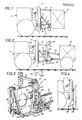
- la figure 1 est une vue latérale schématique d'une forme de réalisation de l'attelage selon l'invention appliquée à un outil porté ;
- la figure 2 est une vue schématique latérale d'une forme de réalisation de l'attelage selon l'invention appliquée à un outil tracté ;
- la figure 3 est une vue en perspective agrandie du dispositif d'attelage de la figure 2 ;
- la figure 4 est une vue schématique partielle du mât élévateur du dispositif d'attelage équipé du contrepoids.
- Figure 1 is a schematic side view of an embodiment of the coupling according to the invention applied to a carried tool;
- Figure 2 is a schematic side view of an embodiment of the coupling according to the invention applied to a towed tool;
- Figure 3 is an enlarged perspective view of the coupling device of Figure 2;
- Figure 4 is a partial schematic view of the lifting mast of the coupling device equipped with the counterweight.
Les vues auxquelles on va se référer pour décrire certaines des formes de réalisation de l'invention sont limitées au dispositif d'attelage proprement dit, les engins de traction ainsi que les outils, qu'ils soient "portés" ou "tractés", pouvant affecter les formes et être destinés aux applications les plus variées.The views to which reference will be made to describe some of the embodiments of the invention are limited to the coupling device itself, the traction units as well as the tools, whether they are "carried" or "towed", which can affect the forms and be intended for the most varied applications.
En se référant, en premier lieu, à la figure 1, on trouve entre un engin de traction 1 et un outil du type porté 2, un attelage désigné par 3 dans son ensemble. Ce dernier se ![]()
![]()
![]()
![]()
De façon connue en soi, le mât élévateur 4 est, de son c8té, solidarisé au tracteur 1, en des points d'articulation fixes 16, 17 et réglables (par vérin, par exemple) 18.In a manner known per se, the
On notera que cette forme de réalisation permet de con- erver à la transmission par joint à la Cardan son angle de départ que l'on maintiendra toujours à une valeur minimale sur l'horizontale.It should be noted that this embodiment makes it possible to keep the starting angle for the transmission by joint with the Cardan joint, which will always be kept at a minimum value on the horizontal.
Le moteur 13 peut être alimenté par le système hydraulique général de l'engin de traction ou par une pompe séparée entraînée par le moteur principal de l'engin.The
Dans la figure 2 qui correspond à une variante du dispositif d'attelage de l'invention plus spécialement adaptée aux outils tractés, le tablier 5 du mât élévateur 4 comporte un bâti pivotant désigné par 19 dans son ensemble. En se référant également à la figure 3, on note que ce bâti 19 pivote autour axes 20, 21 tourillonnés l'un, 20, supérieur à l'extrémité libre du bras 12, l'autre, 21, dans une barre d'attelage 22 prise entre les axes 23 des bras horizontaux 6 de l'attelage trois points. Le bâti proprement dit est constitué par l'assemblage de deux montants 24 disposés en V inversé, dont les pieds sont solidaires d'une platine 25 portant l'axe 21, et les sommets associés à l'axe 20.In FIG. 2 which corresponds to a variant of the coupling device of the invention more particularly adapted to the towed tools, the
La flèche d'attelage 26 de l'outil ou de la machine tractée 31 est articulée en 27 sur cette platine 25.The
Sur les montants 24 est rapportée une plaque 28 formant socle du moteur hydraulique 13 dont on a ébauché l'arbre de prise de force 15, télescopique avec double joint à la Cardan.On the
On remarquera que les bras 6, 7 de l'attelage trois points sont du type télescopique, avec arrêt par chevilles par exemple, de façon à autoriser un réglage des cotes A et B et, de ce fait, de l'alignement, au départ, de l'arbre 15. Des vérins (non représentés) assurant la course du tablier 5 sur le mât 4 peuvent d'ailleurs, également, être utilisés à cette fin.It will be noted that the
Ainsi qu'il ressort nettement de la figure 3, cette disposition de l'attelage selon l'invention permet un débattement de 180° dans le plan horizontal, de part et d'autre, de l'axe de symétrie longitudinal, entre engin tracteur et outil tracté. Elle est notamment optimale dans le cas d'un engin tracteur à roues arrière directrices.As is clear from FIG. 3 , this arrangement of the coupling according to the invention allows a 180 ° movement in the horizontal plane, on either side, of the longitudinal axis of symmetry, between towing machine and towed tool. It is particularly optimal in the case of a tractor with rear steered wheels.
La figure 4 illustre la possibilité d'accrocher au tablier 5 du mât élévateur 4 un contrepoids 29 verrouillé en position par un loquet 30. Celui-ci permet de rendre, si besoin est, l'équilibre au chariot de manutention.FIG. 4 illustrates the possibility of hanging on the
Il va de soi que l'invention ne se limite en aucune manière aux formes de réalisation décrites et représentées mais englobe toute variante d'exécution.It goes without saying that the invention is not limited in any way to the embodiments described and shown but encompasses any variant.
Claims (7)
Applications Claiming Priority (2)
| Application Number | Priority Date | Filing Date | Title |
|---|---|---|---|
| FR7806125A FR2418613A1 (en) | 1978-03-03 | 1978-03-03 | INDEPENDENT POWER TAKE-OFF COUPLING DEVICE |
| FR7806125 | 1978-03-03 |
Publications (2)
| Publication Number | Publication Date |
|---|---|
| EP0004232A1 true EP0004232A1 (en) | 1979-09-19 |
| EP0004232B1 EP0004232B1 (en) | 1981-10-07 |
Family
ID=9205313
Family Applications (1)
| Application Number | Title | Priority Date | Filing Date |
|---|---|---|---|
| EP19790400133 Expired EP0004232B1 (en) | 1978-03-03 | 1979-03-02 | Independently powered linking device |
Country Status (3)
| Country | Link |
|---|---|
| EP (1) | EP0004232B1 (en) |
| DE (1) | DE2960915D1 (en) |
| FR (1) | FR2418613A1 (en) |
Cited By (3)
| Publication number | Priority date | Publication date | Assignee | Title |
|---|---|---|---|---|
| EP0059409A2 (en) * | 1981-02-26 | 1982-09-08 | Deere & Company | Motor vehicle, in particular an agricultural tractor |
| FR2883698A1 (en) * | 2005-04-01 | 2006-10-06 | Chapuis Pere Et Fils Sarl | Tool e.g. auger, coupling device for e.g. quad bike, has rod positioning plate relative to arms for placing plate relative to arms along pivoting course of arms, or for pivoting plate relative to arms for translating plate along course |
| CN104067716A (en) * | 2014-07-15 | 2014-10-01 | 湖南中天龙舟农机有限公司 | Paddy field operation machine automatic out-of-stuck device and out-of-stuck method thereof |
Citations (5)
| Publication number | Priority date | Publication date | Assignee | Title |
|---|---|---|---|---|
| DE1052143B (en) * | 1955-08-03 | 1959-03-05 | Kurt Schroeter | Device coupling for agricultural machinery |
| FR1590121A (en) * | 1968-06-28 | 1970-04-13 | ||
| DE1655950A1 (en) * | 1968-02-10 | 1971-09-09 | Hermann Ziegler | Additional gear for tractor with PTO shaft |
| FR2209489A1 (en) * | 1972-12-13 | 1974-07-05 | Roger Andre | |
| GB1406242A (en) * | 1971-05-12 | 1975-09-17 | Farrant D J | Apparatus for towing impelements from tractors |
-
1978
- 1978-03-03 FR FR7806125A patent/FR2418613A1/en active Granted
-
1979
- 1979-03-02 DE DE7979400133T patent/DE2960915D1/en not_active Expired
- 1979-03-02 EP EP19790400133 patent/EP0004232B1/en not_active Expired
Patent Citations (5)
| Publication number | Priority date | Publication date | Assignee | Title |
|---|---|---|---|---|
| DE1052143B (en) * | 1955-08-03 | 1959-03-05 | Kurt Schroeter | Device coupling for agricultural machinery |
| DE1655950A1 (en) * | 1968-02-10 | 1971-09-09 | Hermann Ziegler | Additional gear for tractor with PTO shaft |
| FR1590121A (en) * | 1968-06-28 | 1970-04-13 | ||
| GB1406242A (en) * | 1971-05-12 | 1975-09-17 | Farrant D J | Apparatus for towing impelements from tractors |
| FR2209489A1 (en) * | 1972-12-13 | 1974-07-05 | Roger Andre |
Cited By (4)
| Publication number | Priority date | Publication date | Assignee | Title |
|---|---|---|---|---|
| EP0059409A2 (en) * | 1981-02-26 | 1982-09-08 | Deere & Company | Motor vehicle, in particular an agricultural tractor |
| EP0059409A3 (en) * | 1981-02-26 | 1984-10-10 | Deere & Company | Motor vehicle, in particular an agricultural tractor |
| FR2883698A1 (en) * | 2005-04-01 | 2006-10-06 | Chapuis Pere Et Fils Sarl | Tool e.g. auger, coupling device for e.g. quad bike, has rod positioning plate relative to arms for placing plate relative to arms along pivoting course of arms, or for pivoting plate relative to arms for translating plate along course |
| CN104067716A (en) * | 2014-07-15 | 2014-10-01 | 湖南中天龙舟农机有限公司 | Paddy field operation machine automatic out-of-stuck device and out-of-stuck method thereof |
Also Published As
| Publication number | Publication date |
|---|---|
| FR2418613A1 (en) | 1979-09-28 |
| DE2960915D1 (en) | 1981-12-17 |
| EP0004232B1 (en) | 1981-10-07 |
| FR2418613B1 (en) | 1980-09-05 |
Similar Documents
| Publication | Publication Date | Title |
|---|---|---|
| JPH0351362B2 (en) | ||
| EP0937827A1 (en) | Motor vehicle with telescopic loader arm | |
| EP0004232A1 (en) | Independently powered linking device | |
| US4699219A (en) | Cultivator drag bar and mounting therefor | |
| US2404925A (en) | Coupling device | |
| FR2580998A1 (en) | HITCH STRUCTURE BETWEEN A TRACTOR VEHICLE AND A TRACT VEHICLE | |
| FR2627660A1 (en) | Coupling system for cutting implement attached to vehicle - has two-section frame with horizontal pivot and rigid and flexible suspension elements | |
| FR2386240A1 (en) | HUNTING DEVICE FOR MACHINES | |
| FR1274580A (en) | Tool carrier tractor designed for public works | |
| EP0520870B1 (en) | Suspension device, especially a multi-link rear suspension device for a motor vehicle | |
| FR2596010A1 (en) | Rear axle assembly with active micro-steering for motor vehicle | |
| FR2660828A1 (en) | TRACTOR AND CHASSIS CARRYING AN AUXILIARY MOTOR TO BE COUPLED TO A TRACTOR. | |
| FR2452862A1 (en) | MEDIAN MOUNTED MOWER | |
| FR2577746A1 (en) | Front implement carrier for an agricultural tractor | |
| JPH0353626Y2 (en) | ||
| JPS635443Y2 (en) | ||
| FR2471308A2 (en) | Powered articulated agricultural motor vehicle - has ground effect supported platform towed by tractor with two powered and steering wheels | |
| FR2532146A1 (en) | Pivoting hitching gear for an agricultural machine pulled by a tractor, particularly a tracklaying tractor | |
| JP6155371B2 (en) | Pricking machine | |
| CH617827A5 (en) | Variable-height motorised cultivating vehicle, especially lawn mower | |
| FR2828673A1 (en) | Driving train for agricultural tractor comprises oscillating arm downstream of rear driving wheel and carrying wheel driven by caterpillar increasing vehicle ground support surface | |
| JPH0411457Y2 (en) | ||
| FR2589668A1 (en) | High-capability lawnmower, pushed by a motor vehicle | |
| FR2562923A1 (en) | Articulated ground levelling roller frame | |
| FR2543095A1 (en) | Device driven by pedalling allowing the support and displacement of soil maintenance apparatus |
Legal Events
| Date | Code | Title | Description |
|---|---|---|---|
| PUAI | Public reference made under article 153(3) epc to a published international application that has entered the european phase |
Free format text: ORIGINAL CODE: 0009012 |
|
| AK | Designated contracting states |
Designated state(s): BE DE GB IT LU NL |
|
| 17P | Request for examination filed | ||
| ITF | It: translation for a ep patent filed |
Owner name: JACOBACCI & PERANI S.P.A. |
|
| GRAA | (expected) grant |
Free format text: ORIGINAL CODE: 0009210 |
|
| AK | Designated contracting states |
Designated state(s): BE DE GB IT LU NL |
|
| REF | Corresponds to: |
Ref document number: 2960915 Country of ref document: DE Date of ref document: 19811217 |
|
| PGFP | Annual fee paid to national office [announced via postgrant information from national office to epo] |
Ref country code: LU Payment date: 19820302 Year of fee payment: 4 |
|
| PG25 | Lapsed in a contracting state [announced via postgrant information from national office to epo] |
Ref country code: LU Free format text: LAPSE BECAUSE OF NON-PAYMENT OF DUE FEES Effective date: 19820331 |
|
| PGFP | Annual fee paid to national office [announced via postgrant information from national office to epo] |
Ref country code: BE Payment date: 19820331 Year of fee payment: 4 |
|
| PG25 | Lapsed in a contracting state [announced via postgrant information from national office to epo] |
Ref country code: NL Effective date: 19821001 |
|
| NLV4 | Nl: lapsed or anulled due to non-payment of the annual fee | ||
| PG25 | Lapsed in a contracting state [announced via postgrant information from national office to epo] |
Ref country code: BE Effective date: 19830302 |
|
| GBPC | Gb: european patent ceased through non-payment of renewal fee | ||
| PG25 | Lapsed in a contracting state [announced via postgrant information from national office to epo] |
Ref country code: DE Effective date: 19831201 |
|
| PG25 | Lapsed in a contracting state [announced via postgrant information from national office to epo] |
Ref country code: GB Effective date: 19881117 |
|
| PLBE | No opposition filed within time limit |
Free format text: ORIGINAL CODE: 0009261 |
|
| STAA | Information on the status of an ep patent application or granted ep patent |
Free format text: STATUS: NO OPPOSITION FILED WITHIN TIME LIMIT |