EP0004155B1 - Moyeu pour roue à rayons et son application - Google Patents
Moyeu pour roue à rayons et son application Download PDFInfo
- Publication number
- EP0004155B1 EP0004155B1 EP79300295A EP79300295A EP0004155B1 EP 0004155 B1 EP0004155 B1 EP 0004155B1 EP 79300295 A EP79300295 A EP 79300295A EP 79300295 A EP79300295 A EP 79300295A EP 0004155 B1 EP0004155 B1 EP 0004155B1
- Authority
- EP
- European Patent Office
- Prior art keywords
- hub
- flange
- spoke
- apertures
- spoke apertures
- Prior art date
- Legal status (The legal status is an assumption and is not a legal conclusion. Google has not performed a legal analysis and makes no representation as to the accuracy of the status listed.)
- Expired
Links
- 230000004323 axial length Effects 0.000 claims description 4
- 238000010276 construction Methods 0.000 description 10
- 210000000887 face Anatomy 0.000 description 9
- 230000002093 peripheral effect Effects 0.000 description 5
- 210000003128 head Anatomy 0.000 description 4
- 230000004048 modification Effects 0.000 description 3
- 238000012986 modification Methods 0.000 description 3
- 238000005452 bending Methods 0.000 description 2
- 230000002411 adverse Effects 0.000 description 1
- 230000000712 assembly Effects 0.000 description 1
- 238000000429 assembly Methods 0.000 description 1
- 230000006835 compression Effects 0.000 description 1
- 238000007906 compression Methods 0.000 description 1
- 238000006073 displacement reaction Methods 0.000 description 1
- 230000000694 effects Effects 0.000 description 1
- 238000003780 insertion Methods 0.000 description 1
- 230000037431 insertion Effects 0.000 description 1
- 238000011068 loading method Methods 0.000 description 1
- 238000003754 machining Methods 0.000 description 1
- 238000004519 manufacturing process Methods 0.000 description 1
- 210000001331 nose Anatomy 0.000 description 1
Images


Classifications
-
- B—PERFORMING OPERATIONS; TRANSPORTING
- B60—VEHICLES IN GENERAL
- B60B—VEHICLE WHEELS; CASTORS; AXLES FOR WHEELS OR CASTORS; INCREASING WHEEL ADHESION
- B60B27/00—Hubs
- B60B27/02—Hubs adapted to be rotatably arranged on axle
- B60B27/023—Hubs adapted to be rotatably arranged on axle specially adapted for bicycles
Definitions
- This invention relates to a hub for a spoked wheel comprising a hub shell having at opposite axial ends thereof a pair of opposed hub flange means; and a hub shaft for rotatably supporting said hub shell with a pair of bearing means disposed between said hub shaft and hub shell; each of said hub flange means having a plurality of spoke apertures each extending generally parallel to the axis of said hub shell, said plurality of spoke apertures being arranged generally concentrically with respect to the axis of said hub shell.
- Such a device is known from US-A-2 702 725 wherein the plurality of spoke apertures comprises a first group and a second group of spoke apertures axially displaced relative to each other, successive ones of said first and second groups alternating with each other in the circumferential direction.
- the first and second groups of the spoke apertures are disposed at smaller and larger spacings, respectively, from the axis of the hub shell.
- Another device is known from FR-A-371 295 wherein the axially displaced alternating first and second groups of the spoke apertures are arranged at a regular spacing from the hub shell axis but wherein no hub shaft is disclosed.
- the first and second groups are provided in separate, axially adjacent, respective flanges provided on the hub shell.
- spokes are inserted through the spoke apertures and their remote ends fixed to a wheel rim, so that the hub, together with the rim and spokes, constitutes the spoked wheel for a bicycle, tricycle or other spoked wheel vehicle.
- the spoke apertures in a conventional hub are formed in each of the hub flanges extending parallel to the rotational and longitudinal axis of the hub shell and arranged uniformly with respect to the hub flange in a direction parallel to said axis.
- the well-known "alternate assembly" is divided into the so-called open type and cross type assemblies.
- the spokes in the open type are inserted into the apertures from the outside face of the hub flange and from the inside face thereof and extend cross-wise without contacting with each other to reach the wheel rim.
- Those in the cross type extend from the inside and outside faces of the hub flange and intersect, extending alternately in directions axially slightly outwards and slightly inwards of the hub flange, and contact each other under pressure at their intersections.
- the inside and outside spokes in the open type assembly are spaced apart at their intersections, whereby each individual spoke is liable to be independently subjected to wind pressure during running of the vehicle. Furthermore, the spokes extending from the inside face of each of the hub flanges are axially spaced at intervals smaller in length than those between the spokes extending from the outside face by the thickness of the two hub flanges, thereby adversely affecting the stiffness of each spoke.
- the cross type assembly has the disadvantage in that the spokes, which interchange outwardly or inwardly at the intersections, tend to twist when bending the intersections, whereby vibrations or load-shifting tend to result in rubbing between the spokes which can be noisy and whereby the stiffness of spoke is reduced.
- the inventor has found in the case of a conventional hub for a spoked wheel the spokes cannot be inserted into the spoke apertures from only one side of the hub flange during assembly of the wheel, for the following reason.
- the spokes are inserted through the spoke apertures in the hub flange, are drawn-out in the direction of rotation of the driven hub and in a direction reversed thereto, and take up tension and compression respectively so as to constitute, together with a rim, the spoked wheel, with the spokes extending in the two different directions, and intersecting at an intermediate portion when inserted into the spoke apertures of the hub flange from one side (the axially inward face) and drawnout from the axially outward face in such a manner that the spokes interfere substantially with each other at their points of intersection giving rise to spoke distortion.
- the present invention provides in a first aspect a hub for a spoked wheel, comprising a hub shell having at opposite axial ends thereof a pair of opposed hub flange means; and a hub shaft for rotatably supporting said hub shell with a pair of bearing means disposed between said hub shaft and hub shell; each of said hub flange means having a plurality of spoke apertures each extending generally parallel to the axis of said hub shell, said plurality of spoke apertures being arranged generally concentrically with respect to the axis of said hub shell and comprising a first group and a second group of spoke apertures axially displaced relative to each other, successive ones of said first and second groups alternating with each other in the circumferential direction, characterized in that said spoke apertures are arranged at a regular spacing from the axis of said hub shell, and each of said hub flanges is formed with stepped portions so as to be partially recessed at a plurality of circumferential positions, the recessed and non-recessed portions of the flanges providing respectively first and
- the present invention provides a hub for a spoked wheel, comprising a hub shell having at opposite axial ends thereof a pair of opposed hub flange means; and a hub shaft for rotatably supporting said hub shell with a pair of bearing means disposed between said hub shaft and hub shell; each of said hub flange means having a plurality of spoke-apertures each extending generally parallel to the axis of said hub shell, said plurality of spoke apertures being arranged generally concentrically with respect to the axis of said hub shell and comprising a first group and a second group of spoke apertures axially displaced relative to each other, successive ones of said first and second groups alternating with each other in the circumferential direction, and wherein-said first and second groups of spoke apertures are disposed in first and second flange portions, respectively, which extend generally circumferentially of said hub flange means characterized in that each of said hub flange means is provided with washer means having spoke apertures which washer means are disposed on at least one face of the hub flange
- all the spokes may be inserted through the bores from one side, namely the axially inward face, of hub flange and drawn out of the axially outward face thereof in the above mentioned two directions.
- Each of the spokes of the spoked wheel may be made in conventional manner of wire material of a predetermined length and strong elasticity, being cranked at one end at an angle of about 90°, and has at the cranked end a head larger in diameter than the wire.
- the spokes to be inserted into both the first and second group spoke apertures have cranked portions of substantially equal length.
- the present invention provides a hub connected by spokes to a wheel rim
- the hub comprises a hub shell having at opposite axial ends thereof a pair of opposed hub flange means; and a hub shaft for rotatably supporting said hub shell with a pair of bearing means disposed between said hub shaft and hub shell; each of said hub flange means having a plurality of spoke apertures each extending generally parallel to the axis of said hub shell said plurality of spoke apertures being arranged generally concentrically with respect to the axis of said hub shell, and comprising a first group and a second group of spoke apertures axially displaced relative to each other, successive ones of said first and second groups alternating with each other in the circumferential direction characterized in that each of said hub flange means includes washer means having spoke apertures which washer means are disposed on at least one face of the hub flange in contact therewith, so as to complete at least one of said first flange portions in which said first group of spoke apertures is provided and said second flange portions
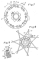
- Fig. 1 shows a hub 1 for the wheel of a spoked wheel for a vehicle, such as a bicycle or tricycle.
- the hub 1 comprises a hub shell 11 including at opposite axial ends thereof a pair of opposed hub flange means in the form of hub flanges 12, 12, a hub shaft 10 rotatably supporting the hub shell 11, with a pair of bearing means disposed between the hub shell 11 and the hub shaft 10.
- Each of the hub flanges 12 is generally disc- shaped and is larger in diameter than the hub shell 11, having an inside face extending radially outwards from the hub shell 11, and has in the vicinity of its outer periphery a plurality of spoke apertures 13 extending in a direction generally parallel to the axis of the hub shell 11, the plurality of apertures 13 being arranged concentrically with respect to the axis of hub shell 11.
- the bearing means comprise ball holders 14 and balls 15 respectively.
- the ball holders 14 are screwthreadedly engaged with screw threads 10a at both axial ends of the hub shaft 10, so that the hub shell 11 is rotatably supported on the hub shaft 10 via the balls 15.
- the hub shaft 10 may be fixed to the frame of the vehicle in conventional manner.
- a hub 1, constituted as above is generally similar to a conventional hub as will be understandable without further detailed description.
- hubs of the invention may equally well be used for both the rear wheel of a bicycle as well as the front wheel as well as for various other two or three (or more) wheeled vehicles.
- the present invention provides that the plurality of spoke apertures 13 in each of the hub flanges 12 comprises two groups: a first group of spoke apertures 13a each arranged in a first portion A at the hub flange 12 and the second group of spoke apertures 13b each arranged in a second portion B, the first and second portions A and B being displaced relative to each other in a direction parallel to the rotational axis of the hub shell 11 and successive ones of said first and second groups of apertures 13a, 13b alternating with each other so that an aperture 13b of the second group is adjacent to two apertures 13a of the first group which are separated thereby, in each case.
- the hub flange 12 is, as shown in Figs. to 3 provided with stepped portions 20 . so as to be partially recessed at a peripheral portion thereof axially inwardly, thereby providing the second portions B, the remaining non-recessed peripheral portions being left as the first portions A.
- the peripheral portion of the hub flange 12 may be axially outwardly recessed.
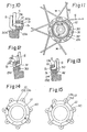
- the hub flange 12 may, as shown in Figs. 4 to 6, be made greater in thickness than is normal and is, at the inwardly and outwardly disposed faces of the peripheral portion thereof, cut away axially to form a plurality of inner recesses 21 and outer recesses 22, thereby providing the first and second portions A and B displaced relative to each other axially of the hub shell 11, or a plurality of washers 30 may, as shown in Figs. 8 to 10, be alternately supported in contact with either side of the hub flange 12, thereby providing the axially relatively displaced first and second portions A and B and apertures 13a and 13b therein.
- spoke apertures 13 in the hub flange 12 may, as shown in Figures 11 to 13, vary in their axial length, the washer means 30 being arranged on the axially inward or outward face of the hub flange 12 with spoke apertures 31 therein aligned with the shorter spoke apertures 30 in the hub flange 12, so as to complete the hub flange means and the respective ones of the first and second portions A and B.
- the hub flange 12 may also, as shown in Figs. 14 and 15, be provided with radially extending stepped noses 40 with spoke apertures 13 therein arranged so as to displace the first and second portions axially of the hub flange 12 and to space the spoke apertures 13a, 13b radially.
- the groups of spoke apertures 13, which are arranged concentrically in the embodiments of Figs. 1 to 15, are, except for those in said Figs. 14 and 15, all spaced substantially equally from the axis of the hub shell 11.
- all the spoke apertures 13, as seen in Figs. 3, 4, 7, 8 and 11, are on an imaginary circle around the rotational axis of hub shell 11.
- the spokes S can be made equal in length because of the uniform distances between the apertures 13 and the wheel rim, and there is no need for the hub flange 12 to be increased in diameter.
- the invention is also applicable to the first and second portions in the embodiment of Figs. 14 and 15, which are relatively displaced radially with respect to the hub flange 12.
- an imaginary circle connecting the spoke apertures 13 positioned radially outwardly of the hub flange should be larger in diameter than normal for a given diameter of the hub shell 11.
- the spoke apertures 13b in the second portions B provided radially outwardly of the first portions A increase the outer diameter of the hub flange 12.
- the outer diameter of the hub flange 12 is minimised, thereby increasing the strength of the wheel and protecting against deformation thereof even with a hub flange 12 of smaller diameter.
- all the spokes S are, as shown in Fig. 2, inserted into the bores 13 from the axially inside face of the hub flange 12 and are assembled thereat so that the heads of the spokes S abut the axially inside face of the hub flange respectively, and can then be drawn out outwardly and generally tangentially of the hub flange 12.
- the spokes S intersect with each other at intermediate portions as shown in Fig. 3 and their remote ends fixed to the wheel rim (not shown).
- the spokes inserted into the first group of spoke apertures 13a in the first portions A are drawn- out rearwardly with respect to the direction of rotation of the driven hub 1 and those inserted into the second group 13b are drawn-out in the reverse direction thereto, whereby each of the spokes in the apertures 13a, 13b of the first and second portions A, B intersects at an intermediate portion another spoke, either contacting it or passing inclose proximity thereto.
- the spokes S are not however displaced axially outwardly or inwardly with respect to the hub axis at the respective intersections X i.e. they are not bent so as to change direction from outward to inward or vice versa.
- spokes S drawn-out through the first portion A are all.positioned outwardly with respect to those spokes S drawn through the second portions B.
- spokes S at the second portions B are all positioned inwardly with respect to those spokes S at the first portions A.
- the spokes can be stretched straight between the hub flanges and the wheel rim without any twisting or bending at the intersections, and the spacing of the spokes at axially larger intervals at both hub flanges improves the stiffness of the spokes when compared with the cross type assembly.
- the spokes at each of the hub flanges are displaced axially outwardly and inwardly thereof and contact with each other or are spaced at small intervals at the intersections as already mentioned above so that too wide intervals between intersecting spokes as in the open type assembly are avoided and the lengths of the intersecting portions of the spokes can be made larger, thereby minimizing the effects of wind pressure in use of the wheel.
- the first group spoke apertures 13a. in the first portions A are substantially equal in axial length to those of the second group 13b in the second portions B, and the first portions A are displaced axially outwardly of the hub shell 11 with respect to the second portions B in the same way as in the embodiment of Figs. 1 to 3, but each of the hub flanges 12 is partially cut-away at its inwardly and outwardly disposed faces to form the first and second portions A and B respectively. Specifically, the hub flange 12 is cut-away at its axially inward face as shown in Fig. 6 to form inner recesses 21 providing the first portions A and at the axially outward face to form outer recesses 22 providing the second portions B.
- the outer recesses 22 are provided with guide faces 23 which extend in the direction of drawing-out of spokes S inserted into the apertures 13b in the second portions B as shown in Figs. 4 to 7.
- the guide faces 23 are also applicable to the construction shown in Figs. 1 to 3, as well as to a construction in which the hub flange 12 is partially axially outwardly swollen at its peripheral portion to form the first portions A in place of the recesses 22 serving as the second portions B in Figs. 4 to 7.
- the inner and outer recesses 21 and 22 are, as shown in Figs. 4 to 7, formed in the inner and outer faces of the hub flange 12 respectively, these recesses are preferred not to overlap with each other in the axial direction of the hub flange 12.
- the first group spoke apertures 13a in the first portions A and the second group apertures 13b in the second portions B are circumferentially spaced at uniform intervals, i.e. in an arrangement as shown in Fig. 7, then the first and second group apertures 13a, 13b are non- uniformly spaced, the spacing between a first group aperture 13a and the adjacent second group aperture 13b being smaller in the forward driving direction Y than in the reverse direction.
- the guide faces 23 indicate the direction of drawing of the spokes when assembled, which is helpful to a worker, especially an unskilled one, in achieving assembly of the spokes S by facilitating correct drawing of them along the respective guide faces 23.
- the spokes S which transmit drive torque from the hub 1 to the wheel rim when the hub is driven are invariably mounted on the first portions A displaced outwardly of the second portions B, whereby the spokes at the first portions A are mounted to the pair of hub flanges 12, 12at axially larger intervals than normal respectively, resulting in improved stiffness of the spokes against transverse loadings applied thereto when e.g. a bicycle with a wheel incorporating a hub of the invention turns a corner.
- the spoke apertures 13, as in the above described embodiments, are equal in axial length and arranged on one imaginary circle concentric with the axis of the hub shell 11, but the first and second portions A and B of the hub flange means are axially displaced relative to each other by means of washers 30 which are provided with apertures 31 which are aligned with the spoke apertures 13 in the hub flange 12.
- the washers 30 may be in the form of discs, as shown in Fig. 8, or in any other convenient-shape e.g. square plates.
- the washers 30 are divided into first washers 30a which are supported on the hub flange 12 in contact with the axially outward face thereof and second washers 30b supported on the hub flange 12 in contact with the axially inward face thereof, so that the first washers 30a provide part of the first portions A as shown in Fig. 9 and the second washers 30b part of the second portions B as shown in Fig. 10.
- FIG. 11 to 13 A further modified construction using washer means 30 is shown in Figs. 11 to 13.
- the washers 30 are arranged only on the axially outward face of the hub flange 12 and instead of a plurality of individual washers 30, there is provided an annular connecting member 32 having a plurality of spoke apertures 31 disposed therein for alignment with respective spoke apertures 13 in the hub flange 12.
- the first group spoke apertures 13a in the first portions A are displaced axially outwardly of the hub flange 12, and the washer means 30 are positioned axially outwardly of the hub flange first group spoke apertures 13a respectively.
- the abovementioned axial displacement of the first group spoke apertures 13a means that the head S, of each of the spokes S is engaged with a said aperture 13a at a position thereof displaced axially with respect to the hub flange 12.
- the abovementioned axial displacement of the first group spoke apertures 13a means that the head S, of each of the spokes S is engaged with a said aperture 13a at a position thereof displaced axially with respect to the hub flange 12.
- recesses 24 into which the heads S, of spoke S are insertable.
- Figs. 14 and 15 have the first and second portions A and B, displaced radially relative to the hub flange 12 through stepped portions 40 respectively, so that the first portions A and first apertures 13a therein are positioned radially inwardly of the hub flange 12 and the second portions B and second apertures 13b therein, radially outwardly with respect to said first portions A.
- first group of spoke apertures 13a in the first portions A in Fig. 14 is arranged radially inwardly with respect to the axis of hub flange 12 relative to the second group of spoke apertures 13b in the second portions b, and the first and second group apertures 13a and 13b are displaced relative to each other circumferentially with respect to the hub flange 12.
- first and second group spoke apertures 13a and 13b are aligned radially with respect to the hub flange 12.
Landscapes
- Engineering & Computer Science (AREA)
- Mechanical Engineering (AREA)
- Rolling Contact Bearings (AREA)
Claims (10)
Applications Claiming Priority (6)
| Application Number | Priority Date | Filing Date | Title |
|---|---|---|---|
| JP1978026850U JPS5737605Y2 (fr) | 1978-02-28 | 1978-02-28 | |
| JP26850/78 | 1978-02-28 | ||
| JP7757678U JPS5845122Y2 (ja) | 1978-06-06 | 1978-06-06 | 二、三輪車用ハブ |
| JP77576/78 | 1978-06-06 | ||
| JP1979013317U JPS5826806Y2 (ja) | 1979-02-02 | 1979-02-02 | 二、三輪車用ハブ |
| JP13317/79 | 1979-02-02 |
Publications (2)
| Publication Number | Publication Date |
|---|---|
| EP0004155A1 EP0004155A1 (fr) | 1979-09-19 |
| EP0004155B1 true EP0004155B1 (fr) | 1982-10-27 |
Family
ID=27280204
Family Applications (1)
| Application Number | Title | Priority Date | Filing Date |
|---|---|---|---|
| EP79300295A Expired EP0004155B1 (fr) | 1978-02-28 | 1979-02-27 | Moyeu pour roue à rayons et son application |
Country Status (3)
| Country | Link |
|---|---|
| US (1) | US4300804A (fr) |
| EP (1) | EP0004155B1 (fr) |
| DE (1) | DE2963917D1 (fr) |
Families Citing this family (21)
| Publication number | Priority date | Publication date | Assignee | Title |
|---|---|---|---|---|
| GB8911454D0 (en) * | 1989-05-18 | 1989-07-05 | Pilkington Plc | Hologram construction |
| US5332295A (en) * | 1991-10-22 | 1994-07-26 | David Vogel | Bicycle hub |
| US6428113B2 (en) * | 1991-12-24 | 2002-08-06 | Rolf Dietrich | Cycle and tensioned spoked wheel assembly |
| US5445439A (en) * | 1991-12-24 | 1995-08-29 | Dietrich; Rolf | Cycle, tensioned spoked wheel assembly and rim therefor |
| US5931544A (en) * | 1991-12-24 | 1999-08-03 | Dietrich; Rolf | Cycle and tensioned spoked wheel assembly |
| US5489147A (en) * | 1993-12-30 | 1996-02-06 | Borsai; Laszlo G. | Hub for spoked wheel axle |
| JP3069284B2 (ja) * | 1996-01-26 | 2000-07-24 | 株式会社シマノ | 自転車用ハブ |
| IT1292238B1 (it) * | 1997-03-28 | 1999-01-29 | Campagnolo Srl | Raggio per ruota di bicicletta e ruota includente tale raggio. |
| US5947565A (en) * | 1997-08-25 | 1999-09-07 | Dietrich; Rolf | Tensioned spoked bicycle wheel assembly and hub therefor |
| NL1007173C1 (nl) * | 1997-09-30 | 1999-03-31 | Chen Yung Tang | Naaf voor een rijwiel. |
| GB2329618A (en) * | 1997-09-30 | 1999-03-31 | Chen Yung Tang | Wheel hub for a bicycle |
| FR2802853B1 (fr) * | 1999-12-23 | 2002-03-29 | Mavic Sa | Moyeu d'une roue a rayons notamment d'une roue de bicyclette |
| IT1321025B1 (it) * | 2000-10-12 | 2003-12-30 | Campagnolo Srl | Mozzo ruota di bicicletta. |
| IT1320727B1 (it) | 2000-10-24 | 2003-12-10 | Campagnolo Srl | Ruota posteriore di bicicletta. |
| DE50103307D1 (de) * | 2000-12-19 | 2004-09-23 | Jiri Krampera | Gespeichtes Fahrrad-Rad |
| EP1719639B1 (fr) * | 2005-05-02 | 2009-07-15 | Campagnolo S.R.L. | Moyeu pour roue à rayons de bicyclette |
| US20070241608A1 (en) * | 2006-04-13 | 2007-10-18 | Kun Teng Industry Co., Ltd. | Bicycle hub and assembly of bicycle hub and spokes |
| EP2826640A1 (fr) * | 2013-07-15 | 2015-01-21 | Joy Cycle Parts (Shanzhen) Co Ltd | Roue de bicyclette améliorée qui empêche la courbure des fils de rayon |
| US9610802B2 (en) * | 2014-06-27 | 2017-04-04 | Enve Composites, Llc | Bicycle wheel hub with molded spoke holes |
| CN107053942B (zh) * | 2017-01-25 | 2019-04-30 | 固德贸易有限公司 | 花毂辐条组合结构 |
| US11904630B1 (en) * | 2023-06-06 | 2024-02-20 | Rolf Dietrich | Bicycle hub and spoke arrangement |
Family Cites Families (6)
| Publication number | Priority date | Publication date | Assignee | Title |
|---|---|---|---|---|
| DE95783C (fr) * | ||||
| DE99859C (fr) * | 1897-12-21 | |||
| FR371295A (fr) * | 1906-11-10 | 1907-03-04 | Emile Joseph Leopold Francois | Système de montage de roues à rayons tangents |
| CH193200A (de) * | 1937-02-09 | 1937-09-30 | Fehrlin Max | Vorrichtung an einerends abgebogenen Drahtspeichen zum Befestigen derselben an Radnaben, die ringförmige Speichenbefestigungsflanschen mit Öffnungen zur Aufnahme der abgebogenen Speichenenden aufweisen. |
| US2702725A (en) * | 1950-07-15 | 1955-02-22 | D P Harris Hardware & Mfg Co I | Spoke wheel and hub therefor |
| US3871710A (en) * | 1973-12-10 | 1975-03-18 | Beatrice Foods Co | Wide flange bicycle hub |
-
1979
- 1979-02-27 DE DE7979300295T patent/DE2963917D1/de not_active Expired
- 1979-02-27 EP EP79300295A patent/EP0004155B1/fr not_active Expired
-
1980
- 1980-08-22 US US06/180,479 patent/US4300804A/en not_active Expired - Lifetime
Also Published As
| Publication number | Publication date |
|---|---|
| US4300804A (en) | 1981-11-17 |
| DE2963917D1 (en) | 1982-12-02 |
| EP0004155A1 (fr) | 1979-09-19 |
Similar Documents
| Publication | Publication Date | Title |
|---|---|---|
| EP0004155B1 (fr) | Moyeu pour roue à rayons et son application | |
| CN1174876C (zh) | 自行车车轮 | |
| US6145938A (en) | Cycle, tensioned spoked wheel assembly and hub therefor | |
| JP2001270305A (ja) | 自転車用ハブ | |
| US5938293A (en) | Cycle, tensioned spoked wheel assembly and hub therefor | |
| US20100066159A1 (en) | Hub body for a bicycle wheel and hub comprising such a hub body | |
| US4329118A (en) | Centrifugal blower wheels | |
| US5947565A (en) | Tensioned spoked bicycle wheel assembly and hub therefor | |
| US5489147A (en) | Hub for spoked wheel axle | |
| US7144089B2 (en) | Spoked wheel for a bicycle and method for its manufacture | |
| US6024414A (en) | Tensioned spoked bicycle wheel assembly and hub therefor | |
| CA2201266C (fr) | Plateau d'entrainement pour vehicule | |
| US6244667B1 (en) | Tensioned spoked bicycle wheel assembly and hub therefor | |
| JP2002144801A (ja) | 自転車用スポーク式車輪 | |
| US6443532B1 (en) | Spoked wheel assembly for a bicycle | |
| US2702725A (en) | Spoke wheel and hub therefor | |
| JP2004352223A (ja) | 自転車用スポーク付き車輪 | |
| JPS582842B2 (ja) | スポ−ク車輪 | |
| US4585277A (en) | Wire wheel with spokes having crank shaped section | |
| JP3080214B2 (ja) | 自転車用ハブ | |
| JPH06219101A (ja) | 自転車用車輪 | |
| JPS6338081Y2 (fr) | ||
| US20230102135A1 (en) | Optimized wheel hub assembly | |
| JPH0550961A (ja) | 自転車用ハブ発電装置 | |
| JP2753929B2 (ja) | 駆動輪用ハブ |
Legal Events
| Date | Code | Title | Description |
|---|---|---|---|
| PUAI | Public reference made under article 153(3) epc to a published international application that has entered the european phase |
Free format text: ORIGINAL CODE: 0009012 |
|
| AK | Designated contracting states |
Designated state(s): BE DE FR GB IT |
|
| 17P | Request for examination filed | ||
| ITF | It: translation for a ep patent filed | ||
| GRAA | (expected) grant |
Free format text: ORIGINAL CODE: 0009210 |
|
| AK | Designated contracting states |
Designated state(s): BE DE FR GB IT |
|
| REF | Corresponds to: |
Ref document number: 2963917 Country of ref document: DE Date of ref document: 19821202 |
|
| PGFP | Annual fee paid to national office [announced via postgrant information from national office to epo] |
Ref country code: BE Payment date: 19840331 Year of fee payment: 6 |
|
| PGFP | Annual fee paid to national office [announced via postgrant information from national office to epo] |
Ref country code: DE Payment date: 19850228 Year of fee payment: 7 |
|
| PG25 | Lapsed in a contracting state [announced via postgrant information from national office to epo] |
Ref country code: BE Effective date: 19860228 |
|
| BERE | Be: lapsed |
Owner name: SHIMANO INDUSTRIAL CY LTD Effective date: 19860228 |
|
| GBPC | Gb: european patent ceased through non-payment of renewal fee | ||
| PG25 | Lapsed in a contracting state [announced via postgrant information from national office to epo] |
Ref country code: DE Effective date: 19861101 |
|
| PG25 | Lapsed in a contracting state [announced via postgrant information from national office to epo] |
Ref country code: GB Effective date: 19881117 |
|
| PGFP | Annual fee paid to national office [announced via postgrant information from national office to epo] |
Ref country code: FR Payment date: 19910212 Year of fee payment: 13 |
|
| ITTA | It: last paid annual fee | ||
| PG25 | Lapsed in a contracting state [announced via postgrant information from national office to epo] |
Ref country code: FR Effective date: 19921030 |
|
| REG | Reference to a national code |
Ref country code: FR Ref legal event code: ST |
|
| PLBE | No opposition filed within time limit |
Free format text: ORIGINAL CODE: 0009261 |
|
| STAA | Information on the status of an ep patent application or granted ep patent |
Free format text: STATUS: NO OPPOSITION FILED WITHIN TIME LIMIT |