EP0004063A1 - Process for producing clad plate - Google Patents
Process for producing clad plate Download PDFInfo
- Publication number
- EP0004063A1 EP0004063A1 EP79100665A EP79100665A EP0004063A1 EP 0004063 A1 EP0004063 A1 EP 0004063A1 EP 79100665 A EP79100665 A EP 79100665A EP 79100665 A EP79100665 A EP 79100665A EP 0004063 A1 EP0004063 A1 EP 0004063A1
- Authority
- EP
- European Patent Office
- Prior art keywords
- cladding
- material plate
- package
- plate
- support material
- Prior art date
- Legal status (The legal status is an assumption and is not a legal conclusion. Google has not performed a legal analysis and makes no representation as to the accuracy of the status listed.)
- Granted
Links
Images

Classifications
-
- B—PERFORMING OPERATIONS; TRANSPORTING
- B23—MACHINE TOOLS; METAL-WORKING NOT OTHERWISE PROVIDED FOR
- B23K—SOLDERING OR UNSOLDERING; WELDING; CLADDING OR PLATING BY SOLDERING OR WELDING; CUTTING BY APPLYING HEAT LOCALLY, e.g. FLAME CUTTING; WORKING BY LASER BEAM
- B23K20/00—Non-electric welding by applying impact or other pressure, with or without the application of heat, e.g. cladding or plating
- B23K20/04—Non-electric welding by applying impact or other pressure, with or without the application of heat, e.g. cladding or plating by means of a rolling mill
Definitions
- the invention relates to a method for producing clad sheets, in particular from 100 to 300 mm thick clad sheets, by roll welding cladding of an evacuated sandwich-like one-sided or two-sided cladding package, the cladding package being sealed all around by a welding frame.
- a plating package formed from a base material plate, a metallic support material plate lying against it and a metallic cover plate separated from the support material plate by a sweat-preventing agent
- a two-sided plating package a metallic support plate formed from two base material plates and between them, separated by a sweat-preventing agent
- the one-sided 'plating package is sealed by a welding frame welded to the base material plate and the cover plate and the two-sided plating package is sealed by a welding frame welded all around to the base material plates.
- the degree of deformation is understood to be the ratio of the reduction in the thickness (reduction in thickness) to the initial thickness of the rolling stock, whereby several passes can be used.
- This reduction in thickness of the plating package has so far made it possible in practice only with great effort to produce properly plated sheets with a thickness of more than 100 mm.
- insurmountable difficulties arose as a result of the previously required high degree of deformation during the roll welding plating of the plating package and the resulting large initial thickness of the plating package.
- the invention has for its object to provide a method of the type described above for the production of clad sheet metal, by which it is possible to find sufficiency with only small degrees of deformation, which can be applied in only a few passes, but one perfect roll-weld connection of the support material plate to the base material plate is ensured.
- the plan machining of the sides of the base material plate and the support material plate that come into contact enables the two plates to come into contact at any point on the sides that come into contact with a very low degree of deformation.
- the measure of using a subframe of the type described and inserting the subframe into the plating package while leaving an air gap with respect to the welding frame ensures that metal oxides, such as those produced when the package is welded, do not reach the support material plate, thereby causing a Immigration of oxygen to the support material plates is prevented.
- the subframe remains free of the tarnishing that occurs as a result of the heat during welding.
- the subframe also stiffens the package, so that the breakdown or curvature effect feared during roll welding cladding occurs less easily.
- the welded connection of the welding frame with the base material plate and / or the cover plate tears, as a result of which air can penetrate into the plating package when it is assembled in a conventional manner.
- the plating package according to the invention even if the welded joint becomes leaky, the penetration of air. to the support material plate, since the auxiliary frame on the base material plate or cover plate creates an additional seal.
- the deformation preceding the package construction can take place in an embodiment of the method according to the invention can be avoided by using melted plates as the base material after the electroslag remelting process (ESR process) or after the Böhler electro slag topping process (BES T process).
- ESR process electroslag remelting process
- BES T process Böhler electro slag topping process
- An explanation and description of the BEST method is set out in AT-PS 282.845 and GB-PS 1.254.546.
- the use of plates melted by the electroslag remelting process (ESR process) or by the Böhler electro slag topping process (BEST process) eliminates the need for a high degree of deformation due to the homogeneity and purity that can be achieved with this process for the base material.
- the subframe is machined to a bright metal finish on all sides and is machined on its side facing the base material plate (s).
- the plane-machined surface of the base material plate with a maximum permissible unevenness deviation of 1% of the thickness of the base material plate and the plane-machined surface of the support material plate and that of the subframe with a maximum unevenness deviation of 1 mm are expediently produced.
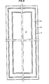
- Fig. 1 shows a one-sided and Fig. 2 a two-sided plating package in section.
- Fig. 3 shows a section taken along the line III-III of Fig. 2.
- the required dimensions of the finished clad sheet were 3200 x .1400 x 270 x 13.5 mm, with 270 mm being the required thickness of the base material and 13.5 mm being the required thickness of the support material.
- ESR process pre-slabs with the dimensions 2800 x 1600 x 350 mm. This pre-slab was first rolled out to a size of 3260 x 1600 x 300 mm in order to achieve a square format. The pre-slab was then scooped and subjected to an ultrasonic test. One side of the pre-slab was ground flat, taking special care to avoid grinding pits. The maximum deviation of the surface-ground surface from the geometrically exact flatness was 3 mm, that is 1% of the thickness of the base material plate.
- the support material plate was rolled and cut, the support material plate prepared in this way having a size of approximately 3020 x 1480 x 16 mm. Then the support material plate was also ground on one side, whereby care was also taken to avoid grinding pits and a maximum deviation from the geometrically flat surface was set at 1 mm. After rolling and cutting, the cover sheet had the dimensions approximately 3600 x 650 x 60 mm.
- a subframe the internal dimensions of which were dimensioned a little larger than the length and width of the support material plate, was made with a width of 30 mm and a height of 15 mm in weldable steel quality with about 0.1% C and machined blank on all sides, whereby the two flat sides of the subframe were ground flat with a maximum unevenness of 1 mm.
- a plating package was assembled from the base material plate 1, the support material plate 2, the cover plate 3 and the auxiliary frame 4, as shown in FIG. 1.
- a sweat-preventing agent 5 was provided between the cover plate and the support material plate.
- a welding frame 6 was inserted between the cover plate 3 and the base material plate 1, leaving an air gap 7 to the auxiliary frame 4 and welded tightly to the base material plate 1 and the cover plate.
- the package thus completed was evacuated through a vent, not shown, whereupon the opening was closed.
- the plating package was then heated to the rolling temperature and rolled in only two passes onto a raw sheet approximately 3500 x 1600 x 338 mm in size. The degree of deformation was about 10%.
- the finished plate was available in the desired dimensions.
- the clad sheet was ultrasonically sonicated. No defects in the bond between the support and base material plate could be found.
- the subframe 4 has a height that corresponds to the height of the two support material plates 2 inserted between the base material plates 1, which are separated from one another by a sweat-preventing agent 5.
- the sealing bar 6 is also arranged leaving an air gap 7 between it and the auxiliary frame 4.
Landscapes
- Engineering & Computer Science (AREA)
- Mechanical Engineering (AREA)
- Pressure Welding/Diffusion-Bonding (AREA)
Abstract
Description
Die Erfindung betrifft ein Verfahren zum Herstellen von plattierten Blechen, insbesondere von 100 bis 300 mm dicken plattierten Blechen, durch Walzschweißplattieren eines evakuierten sandwichartig aus Grund- und Auflagewerkstoff gebildeten, ein- oder zweiseitigen Plattierpaketes, wobei das Plattierpaket rundum von einem Schweißrahmen abgedichtet wird.The invention relates to a method for producing clad sheets, in particular from 100 to 300 mm thick clad sheets, by roll welding cladding of an evacuated sandwich-like one-sided or two-sided cladding package, the cladding package being sealed all around by a welding frame.
Als einseitiges Plattierpaket wird ein aus einer Grundwerkstoffplatte, einer an dieser anliegenden metallischen Auflagewerkstoffplatte und einer durch ein schweißhinderndes Mittel von der Auflagewerkstoffplatte getrennten metallischen Deckplatte gebildetes Plattierpaket und als zweiseitiges Plattierpaket ein aus zwei Grundwerkstoffplatten und zwischen diesen liegenden, durch ein schweißhinderndes Mittel getrennten metallischen Auflagewerkstoffplatten gebildetes Paket verstanden, wobei das einseitige 'Plattierpaket durch einen mit der Grundwerkstoffplatte und der Deckplatte verschweißten Schweißrahmen und das zweiseitige Plattierpaket durch einen mit den Grundwerkstoffplatten rundum verschweißten Schweißrahmen abgedichtet ist.As a one-sided plating package, a plating package formed from a base material plate, a metallic support material plate lying against it and a metallic cover plate separated from the support material plate by a sweat-preventing agent, and as a two-sided plating package, a metallic support plate formed from two base material plates and between them, separated by a sweat-preventing agent Package understood, the one-sided 'plating package is sealed by a welding frame welded to the base material plate and the cover plate and the two-sided plating package is sealed by a welding frame welded all around to the base material plates.
Im Stahlbau, insbesondere für den Bau von Kernkraftwerken, benötigt man in zunehmendem Maß plattierte Grobbleche in Blechdicken über 100 mm bis zu 300 mm. Die Herstellung solch dicker plattierter Bleche bereitete bisher große Schwierigkeiten.In steel construction, in particular for the construction of nuclear power plants, plated plates are increasingly required in Sheet thicknesses over 100 mm up to 300 mm. The production of such thick clad sheets has hitherto been very difficult.
Bisher war es erforderlich, zur einwandfreien Bindung des Auflagewerkstoffes mit dem Grundwerkstoff Verformungsgrade von über 50 %, die nur in einer Vielzahl von Walzstichen erreicht werden können, anzuwenden. Unter Verformungsgrad wird das Verhältnis von Stichabnahme (Dickenminderung) zu Anfangsdicke des Walzgutes verstanden, wobei mehrere Stiche angewendet werden können. Durch diese Dickenreduzierung des Plattierpaketes war es in der Praxis bisher nur mit einem großen Aufwand möglich, einwandfrei plattierte Bleche in über 100 mm Dicke herzustellen. Bei der Erzeugung von plattierten Blechen in Dicken über 150 mm kam es infolge des bisher notwendigen hohen Verformungsgrades beim Walzschweißplattieren des Plattierpaketes und der sich daraus ergebenden großen Anfangsdicke des Plattierpaketes zu unüberwindbaren Schwierigkeiten. Man war daher gezwungen, andere Verfahren anzuwenden, wie z.B. das Sprengplattieren, bei welchen Verfahren jedoch hinsichtlich der erzielbaren Blechgröße enge Grenzen gesetzt sind.Until now, it was necessary to use degrees of deformation of over 50%, which can only be achieved in a large number of roll passes, in order to bond the support material to the base material properly. The degree of deformation is understood to be the ratio of the reduction in the thickness (reduction in thickness) to the initial thickness of the rolling stock, whereby several passes can be used. This reduction in thickness of the plating package has so far made it possible in practice only with great effort to produce properly plated sheets with a thickness of more than 100 mm. In the production of plated sheets in thicknesses over 150 mm, insurmountable difficulties arose as a result of the previously required high degree of deformation during the roll welding plating of the plating package and the resulting large initial thickness of the plating package. One was therefore forced to use other methods, e.g. explosive plating, in which methods there are narrow limits with regard to the achievable sheet size.
Die Erfindung stellt sich die Aufgabe, ein Verfahren der eingangs beschriebenen Art zum Herstellen von plattierten Blechen zu schaffen, durch welches es möglich ist, mit nur geringen Verformungsgraden, die in nur einigen wenigen Walzstichen aufgebracht werden können, das Auslangen zu finden, wobei jedoch eine einwandfreie Walzschweißverbindung der Auflagewerkstoffplatte mit der Grundwerkstoffplatte sichergestellt ist.The invention has for its object to provide a method of the type described above for the production of clad sheet metal, by which it is possible to find sufficiency with only small degrees of deformation, which can be applied in only a few passes, but one perfect roll-weld connection of the support material plate to the base material plate is ensured.
Diese Aufgabe wird durch die Kombination folgender Maßnahmen gelöst:
- - durch spanabhebende, vorzugsweise durch Hobeln oder Bandschleifen erfolgende Planbearbeitung der Grundwerkstoffplatte(n) und der Auflagewerkstoffplatte(n) an den miteinander zur Anlage gelangenden Seiten,
- - dadurch, daß vor dem Verschweißen des Plattierpaketes ein die Auflagewerkstoffplatte(n) peripher umgebender Hilfsrahmen mit etwa einer die Höhe der übereinanderliegenden Auflagewerkstoffplatten beim zweiseitigen Plattierpaket bzw. der Auflagewerkstoffplatte beim einseitigen Plattierpaket aufweisenden Höhe eingesetzt wird,
- - dadurch, daß zwischen dem Schweißrahmen und dem Hilfsrahmen ein Luftspalt freigelassen wird, und
- - dadurch, daß das Walzschweißen unter Anwendung eines Gesamtverformungsgrades von weniger als 50 %, vorzugsweise weniger als 30 % in maximal 5 Walzstichen durchgeführt wird.
- - by machining, preferably by planing or belt grinding, plan machining of the base material plate (s) and the support material plate (s) on the sides that come into contact with one another,
- in that, before the welding of the plating package, a subframe surrounding the support material plate (s) peripherally is inserted with approximately a height having the height of the superimposed support material plates in the two-sided plating package or the support material plate in the one-sided plating package,
- - In that an air gap is left between the welding frame and the subframe, and
- - In that the roll welding is carried out using a total degree of deformation of less than 50%, preferably less than 30% in a maximum of 5 passes.
Die Planbearbeitung der zur Anlage gelangenden Seiten der Grundwerkstoffplatte und der Auflagewerkstoffplatte ermöglicht den Kontakt der beiden Platten an jeder Stelle der zur Anlage gelangenden Seiten schon bei einem sehr geringen Verformungsgrad. Durch die Maßnahme, einen Hilfsrahmen der beschriebenen Art zu verwenden und den Hilfsrahmen unter Freilassung eines Luftspaltes gegenüber dem Schweißrahmen in das Plattierpaket einzusetzen, wird er- reicht, daß Metalloxyde, wie sie beim Verschweißen des Paketes entstehen, nicht bis zur Auflagewerkstoffplatte gelangen, wodurch ein Einwandern des Sauerstoffes zu den Auflagewerkstoffplatten verhindert wird. Der Hilfsrahmen bleibt im Gegensatz zum Schweißrahmen frei von durch die Wärmeeinwirkung beim Schweißen entstehenden Anlauffarben.The plan machining of the sides of the base material plate and the support material plate that come into contact enables the two plates to come into contact at any point on the sides that come into contact with a very low degree of deformation. The measure of using a subframe of the type described and inserting the subframe into the plating package while leaving an air gap with respect to the welding frame ensures that metal oxides, such as those produced when the package is welded, do not reach the support material plate, thereby causing a Immigration of oxygen to the support material plates is prevented. In contrast to the welding frame, the subframe remains free of the tarnishing that occurs as a result of the heat during welding.
Der Hilfsrahmen bewirkt weiters eine Versteifung des Paketes, sodaß der beim Walzschweißplattieren gefürchtete Aufschlüsselungs- bzw.'Krümmungseffekt weniger leicht auftritt. Durch das Aufschlüsseln des plattierten Bleches reißt in der Regel die Schweißverbindung des Schweißrahmens mit der Grundwerkstoffplatte und/oder der Deckplatte ein, wodurch es zum Eindringen von Luft in das Plattierpaket, wenn dieses nach herkömmlicher Art zusammengestellt ist, kommt. Beim erfindungsgemäßen Plattierpaket wird selbst bei einem Undichtwerden der Schweißverbindung das Eindringen von Luft. zur Auflagewerkstoffplatte verhindert, da der Hilfsrahmen an der Grundwerkstoffplatte bzw. dem Deckblech eine zusätzliche Abdichtung bewirkt.The subframe also stiffens the package, so that the breakdown or curvature effect feared during roll welding cladding occurs less easily. By breaking the clad sheet, the welded connection of the welding frame with the base material plate and / or the cover plate tears, as a result of which air can penetrate into the plating package when it is assembled in a conventional manner. With the plating package according to the invention, even if the welded joint becomes leaky, the penetration of air. to the support material plate, since the auxiliary frame on the base material plate or cover plate creates an additional seal.
Bei kombinierter Anwendung der erfindungsgemäßen Maßnahmen ist es möglich, schon mit Verformungsgraden von 10 % eine lückenlose Bindung zwischen der Auflagewerkstoffplatte und der Grundwerkstoffplatte zu erreichen. Dadurch ist es beispielsweise möglich, aus einer 330 mm dicken Vorbramme ein plattiertes Blech mit einer Grundwerkstoffdicke von 300 mm Dicke herzustellen.When the measures according to the invention are used in combination, it is possible to achieve a seamless bond between the support material plate and the base material plate with degrees of deformation of 10%. This makes it possible, for example, to produce a clad sheet with a base material thickness of 300 mm from a 330 mm thick pre-slab.
Verwendet man als Grundwerkstoff im Blockguß oder im Stranggießverfahren erschmolzene Brammen, so ist es erforderlich, diese mit einem Verformungsgrad von mindestens 67 % zu walzen, damit die mechanischen Eigenschaften des Grundwerkstoffes den gestellten Anforderungen entsprechen und auch die Ultraschallprüfung ein befriedigendes Ergeb- nis ergibt. Um nach dem Blockgieß- oder nach dem Stranggießverfahren hergestellte Grundwerkstoffplatten für das erfindungsgemäße Verfahren verwenden zu können, ist es somit notwendig diese einer Verformung mit hohem Verformungsgrad vor dem Zusammenbau des Plattierpaketes zu unterwerfen, da das Plattierpaket selbst nur mehr einer Verformung mit sehr geringem Verformungsgrad unterzogen wird. Die dem Paketbau vorausgehende Verformung kann in einer Ausgestaltung des erfindungsgemäßen Verfahrens dadurch vermieden werden, daß als Grundwerkstoff nach dem Elektroschlackeumschmelzverfahren (ESU-Verfahren) oder nach dem Böhler-Electro-Slag-Topping-Verfahren (B.E.S.T.-Verfahren) erschmolzene Platten verwendet werden. Eine Erläuterung und Beschreibung des B.E.S.T.-Verfahrens ist in der AT-PS 282.845 bzw. GB-PS 1,254.546 dargelegt. Durch die Verwendung von nach dem Elektroschlackeumschmelzverfahren (ESU-Verfahren) oder nach dem Böhler-Electro-Slag-Topping-Verfahren (B.E.S.T.-Verfahren) erschmolzenen Platten erübrigt sich infolge der bei diesem Verfahren erzielbaren Homogenität und Reinheit (Einschlußfreiheit) die Anwendung eines starken Verformungsgrades für den Grundwerkstoff. Die Verwendung dieser bereits ohne Walzvorgang "ultraschallreinen" Werkstoffe für die Grundwerk- 'stoffplatten bietet gegenüber den nach dem herkömmlichen Blockgießverfahren.erschmolzenen Werkstoffen weiters den Vorteil, daß bei der üblich vorgesehenen hundertprozentigen Ultraschallprüfung der fertig plattierten Bleche vom Grundwerkstoff verursachte Fehleranzeigen nicht auftreten, was bei Grundwerkstoffen, die nach herkömmlichen Blockgußverfahren hergestellt wurden, nie ganz auszuschließen ist, wodurch bei Verwendung letzterer Grundwerkstoffe ein Erkennen eines Bindefehlers erheblich erschwert, wenn nicht gar unmöglich gemacht wird.If slab is used as the base material in ingot casting or in the continuous casting process, it is necessary to roll it with a degree of deformation of at least 67% so that the mechanical properties of the base material meet the requirements and the ultrasound test also gives a satisfactory result. In order to be able to use base material plates produced by the block casting or the continuous casting method for the method according to the invention, it is therefore necessary to subject them to a deformation with a high degree of deformation before the assembly of the plating package, since the plating package itself is only subjected to a deformation with a very low degree of deformation becomes. The deformation preceding the package construction can take place in an embodiment of the method according to the invention can be avoided by using melted plates as the base material after the electroslag remelting process (ESR process) or after the Böhler electro slag topping process (BES T process). An explanation and description of the BEST method is set out in AT-PS 282.845 and GB-PS 1.254.546. The use of plates melted by the electroslag remelting process (ESR process) or by the Böhler electro slag topping process (BEST process) eliminates the need for a high degree of deformation due to the homogeneity and purity that can be achieved with this process for the base material. The use of these "ultrasound-pure" materials for the base material plates, already without rolling, offers the advantage over the materials melted according to the conventional ingot casting method that the error indications caused by the base material do not occur in the usual 100% ultrasound inspection of the finished clad sheets, which does not occur with Base materials that have been produced by conventional ingot casting processes can never be completely ruled out, which makes the detection of a binding error considerably more difficult, if not impossible, when using the latter base materials.
. Es ist von Vorteil, wenn der Hilfsrahmen allseits metallisch blank bearbeitet und an seiner (seinen) zur (zu den) Grundwerkstoffplatte(n) gerichteten Seite(n) spanabhebend planbearbeitet wird.. It is advantageous if the subframe is machined to a bright metal finish on all sides and is machined on its side facing the base material plate (s).
Um mit besonders niedrigen Verformungsgraden das Auslangen zu finden, ist zweckmäßig die planbearbeitete Fläche der Grundwerkstoffplatte mit einer maximal zulässigen Unebenheitsabweichung von 1 % der Dicke der Grundwerkstoffplatte und die planbearbeitete Fläche der Auflagewerkstoffplatte und die des Hilfsrahmens mit einer maximalen Unebenheitsabweichung von 1 mm hergestellt.In order to be able to cope with particularly low degrees of deformation, the plane-machined surface of the base material plate with a maximum permissible unevenness deviation of 1% of the thickness of the base material plate and the plane-machined surface of the support material plate and that of the subframe with a maximum unevenness deviation of 1 mm are expediently produced.
Das erfindungsgemäße Verfahren ist nachfolgend anhand eines Beispieles sowie anhand der Zeichnung näher erläutert. Fig..1 zeigt ein einseitiges und Fig. 2 ein zweiseitiges Plattierpaket im Schnitt. Fig. 3 stellt einen nach der Linie III-III der Fig. 2-geführten Schnitt dar.The method according to the invention is explained in more detail below using an example and the drawing. Fig. 1 shows a one-sided and Fig. 2 a two-sided plating package in section. Fig. 3 shows a section taken along the line III-III of Fig. 2.
Beispiel: Es sollte ein plattiertes Blech hergestellt werden, dessen Grundwerkstoff aus einem Kohlenstoffstahl der Qualität H II nach der Norm DIN 17155 besteht. Als Auflagewerkstoff war ein Chrom-Nickel-Stahl der Qualität X 10.Cr Ni Nb 18 9 vorgesehen.Example: A clad sheet should be produced, the base material of which consists of carbon steel of quality H II according to the standard DIN 17155. A chromium-nickel steel of the quality X 10.Cr Ni Nb 18 9 was provided as the support material.
Die geforderten Abmessungen des fertigplattierten Bleches betrugen 3200 x .1400 x 270 x 13,5 mm, wobei 270 mm die geforderte.Dicke des Grundwerkstoffes und 13,5 mm die geforderte Dicke des Auflagewerkstoffes waren.The required dimensions of the finished clad sheet were 3200 x .1400 x 270 x 13.5 mm, with 270 mm being the required thickness of the base material and 13.5 mm being the required thickness of the support material.
Da nur ein einzelnes Blech hergestellt werden sollte, wurde ein einseitiges Plattierpaket gebildet, wobei für das Deckblech ein Blech in der Dicke von 60 mm verwendet wurde, welches aus einem vakuumbehandelten, unberuhigten Stahl mit folgender chemischer Zusammensetzung gewalzt wurde: 0,006 % C, 0,50 % Mn, 0,001 % P, 0,001 % S, Rest Eisen mit erschmelzungsbedingten Verunreinigungen. Als Ausgangsmaterial für die Grundwerkstoffplatte wurde eine nach dem Elektroschlackeumschmelzverfahren. (ESU-Verfahren) hergestellte Vorbramme mit den Abmessungen 2800 x 1600 x 350 mm vorgesehen. Diese Vorbramme wurde zunächst, um ein eckiges Format zu erzielen, auf das Format 3260 x 1600 x 300 mm ausgewalzt. Danach wurde die Vorbramme geschopft und einer Ultraschallprüfung unterzogen. Eine Seite der Vorbramme wurde plangeschliffen, wobei insbesondere darauf geachtet wurde, daß Schleifgruben vermieden wurden. Als maximale Abweichung der plangeschliffenen Oberfläche von der geometrisch exakten Planheit wurden 3 mm, das ist 1 % der Dicke der Grundwerkstoffplatte, festgelegt.Since only a single sheet was to be produced, a one-sided plating package was formed, a sheet with a thickness of 60 mm being used for the cover sheet, which was rolled from a vacuum-treated, unsteady steel with the following chemical composition: 0.006% C, 0, 50% Mn, 0.001% P, 0.001% S, remainder iron with impurities due to melting. The starting material for the base material plate was one using the electroslag remelting process. (ESR process) pre-slabs with the dimensions 2800 x 1600 x 350 mm. This pre-slab was first rolled out to a size of 3260 x 1600 x 300 mm in order to achieve a square format. The pre-slab was then scooped and subjected to an ultrasonic test. One side of the pre-slab was ground flat, taking special care to avoid grinding pits. The maximum deviation of the surface-ground surface from the geometrically exact flatness was 3 mm, that is 1% of the thickness of the base material plate.
Parallel zu diesen-Vorgängen wurde die Auflagewerkstoffplatte gewalzt und zugeschnitten, wobei die so vorbereitete Auflagewerkstoffplatte etwa die Abmessungen 3020 x 1480 x 16 mm aufwies. Anschließend wurde die Auflagewerkstoffplatte an einer Seite ebenfalls plangeschliffen, wobei ebenfalls auf die Vermeidung von Schleifgruben geachtet und eine maximale Abweichung von der geometrisch ebenen Fläche mit 1 mm festgelegt wurde. Das Deckblech wies nach dem Walzen und Zuschneiden etwa die Abmessungen 3600 x 650 x 60 mm auf.In parallel to these processes, the support material plate was rolled and cut, the support material plate prepared in this way having a size of approximately 3020 x 1480 x 16 mm. Then the support material plate was also ground on one side, whereby care was also taken to avoid grinding pits and a maximum deviation from the geometrically flat surface was set at 1 mm. After rolling and cutting, the cover sheet had the dimensions approximately 3600 x 650 x 60 mm.
Ein Hilfsrahmen, dessen Innenabmessungen um ein geringes größer bemessen wurden als die Länge und Breite der Auflagewerkstoffplatte, wurde mit der Breite von 30 mm und mit einer Höhe von 15 mm in schweißbarer Stahlqualität mit etwa 0,1 % C hergestellt und allseits blank bearbeitet, wobei die beiden Planseiten des Hilfsrahmens plangeschliffen wurden und zwar mit einer maximalen Unebenheitsabweichung von 1 mm.A subframe, the internal dimensions of which were dimensioned a little larger than the length and width of the support material plate, was made with a width of 30 mm and a height of 15 mm in weldable steel quality with about 0.1% C and machined blank on all sides, whereby the two flat sides of the subframe were ground flat with a maximum unevenness of 1 mm.
Aus der Grundwerkstoffplatte 1, der Auflagewerkstoffplatte 2, dem Deckblech 3 und dem Hilfsrahmen 4 wurde ein Plattierpaket zusammengefügt, wie es in Fig. 1 dargestellt ist. Zwischen der Deckplatte und der Auflagewerkstoffplatte wurde ein schweißhinderndes Mittel 5 vorgesehen. Ein Schweißrahmen 6 wurde zwischen der Deckplatte 3 und der Grundwerkstoffplatte 1 unter Freilassung eines Luftspaltes 7 zum Hilfsrahmen 4 eingefügt und mit der Grundwerkstoffplatte 1 sowie dem Deckblech dicht verschweißt.A plating package was assembled from the
Das so fertiggestellte Paket wurde durch eine nicht dargestellte Entlüftungsöffnung evakuiert, worauf die öffnung geschlossen wurde. Sodann wurde das Plattierpaket auf Walztemperatur erhitzt und in nur zwei Stichen auf eine Rohtafel mit etwa den Abmessungen 3500 x 1600 x 338 mm gewalzt. Der Verformungsgrad betrug dabei etwa 10 %. Nach dem Aufschneiden des Paketes, Entfernen des Deckbleches und Beschneiden der Ränder lag das fertigplattierte Blech in den gewünschten Abmessungen vor.The package thus completed was evacuated through a vent, not shown, whereupon the opening was closed. The plating package was then heated to the rolling temperature and rolled in only two passes onto a raw sheet approximately 3500 x 1600 x 338 mm in size. The degree of deformation was about 10%. To After cutting the package, removing the cover plate and trimming the edges, the finished plate was available in the desired dimensions.
Das plattierte Blech wurde ultrageschallt. Es konnten keine Fehlstellen der Bindung zwischen Auflage- und Grundwerkstoffplatte gefunden werden.The clad sheet was ultrasonically sonicated. No defects in the bond between the support and base material plate could be found.
In Fig. 2 ist ein zweiseitiges Plattierpaket.gezeigt, welches analog zu dem einseitigen Plattierpaket hergestellt ist. Anstelle des Deckbleches ist hier eine zweite Grundwerkstoffplatte 1 vorgesehen. Der Hilfsrahmen 4 weist eine Höhe auf, die der Höhe der beiden zwischen den Grundwerkstoffplatten 1 eingesetzten Auflagewerkstoffplatten 2, welche durch ein schweißhinderndes Mittel 5 voneinander getrennt sind, entspricht. Die Schweißleiste 6 ist ebenfalls unter Freilassung eines Luftspaltes 7 zwischen ihr und dem Hilfsrahmen 4 angeordnet.2 shows a two-sided plating package, which is produced analogously to the one-sided plating package. Instead of the cover plate, a second
Arbeitet man nach dem erfindungsgemäßen Verfahren, so tritt vollständiges Verschweißen der Grundwerkstoffplatte mit der Auflagewerkstoffplatte schon bei einem Gesamtverformungsgrad von etwa 10 % ein, d.h. daß das Walzschweißen nach Anwendung eines Verformungsgrades von etwa 10 % bereits beendet ist. Es ist jedoch möglich, das Paket weiter auf eine geringere Dicke zu verwalzen, und zwar entweder in gleicher Walzhitze oder unter separater Aufwärmung. Auch kann ein Weiterwalzen des nach Trennen des Plattierpaketes vorliegenden plattierten Bleches an das erfindungsgemäße Verfahren angeschlossen werden.If one works according to the method according to the invention, complete welding of the base material plate to the support material plate occurs with a total degree of deformation of about 10%, i.e. that the roll welding is already finished after applying a degree of deformation of about 10%. However, it is possible to roll the package further to a smaller thickness, either in the same rolling heat or with separate heating. Further rolling of the clad sheet present after separation of the cladding package can also be connected to the method according to the invention.
Claims (4)
Applications Claiming Priority (2)
| Application Number | Priority Date | Filing Date | Title |
|---|---|---|---|
| AT180678A AT359810B (en) | 1978-03-14 | 1978-03-14 | METHOD FOR PRODUCING PLATED SHEETS |
| AT1806/78 | 1978-03-14 |
Publications (2)
| Publication Number | Publication Date |
|---|---|
| EP0004063A1 true EP0004063A1 (en) | 1979-09-19 |
| EP0004063B1 EP0004063B1 (en) | 1981-07-15 |
Family
ID=3521371
Family Applications (1)
| Application Number | Title | Priority Date | Filing Date |
|---|---|---|---|
| EP19790100665 Expired EP0004063B1 (en) | 1978-03-14 | 1979-03-06 | Process for producing clad plate |
Country Status (3)
| Country | Link |
|---|---|
| EP (1) | EP0004063B1 (en) |
| AT (1) | AT359810B (en) |
| DE (1) | DE2960472D1 (en) |
Cited By (10)
| Publication number | Priority date | Publication date | Assignee | Title |
|---|---|---|---|---|
| US4493452A (en) * | 1980-12-02 | 1985-01-15 | Voest-Alpine Aktiengesellschaft | Method of producing a plate of steel |
| EP0132937A1 (en) * | 1983-06-04 | 1985-02-13 | Nippon Steel Corporation | Method for producing a clad plate by rolling |
| DE3625755A1 (en) * | 1986-07-30 | 1988-02-11 | Hoesch Stahl Ag | Composite material |
| EP0406688A2 (en) * | 1989-07-04 | 1991-01-09 | Nkk Corporation | Method for manufacturing titanium clad steel plate |
| US5286309A (en) * | 1990-12-25 | 1994-02-15 | Nkk Corporation | Electric-resistance-welded steel pipe with high strength |
| DE102015102961A1 (en) | 2015-03-02 | 2016-09-08 | Thyssenkrupp Ag | Method for producing a material composite and provisional composite |
| DE102018209918A1 (en) | 2018-06-19 | 2019-12-19 | Thyssenkrupp Ag | Process for producing a starting block for further processing into a composite material, process for producing a composite material and starting block |
| WO2020182613A1 (en) * | 2019-03-13 | 2020-09-17 | Thyssenkrupp Steel Europe Ag | Flat product package, method for producing a material composite, and use thereof |
| CN112548499A (en) * | 2020-12-05 | 2021-03-26 | 安徽宝恒新材料科技有限公司 | Processing method of three-layer composite steel plate |
| US11185943B2 (en) | 2016-11-18 | 2021-11-30 | Sms Group Gmbh | Method and device for producing a continuous strip-shaped composite material |
Families Citing this family (5)
| Publication number | Priority date | Publication date | Assignee | Title |
|---|---|---|---|---|
| JPS6036354B2 (en) * | 1979-07-02 | 1985-08-20 | 三菱マテリアル株式会社 | Manufacturing method for metal composites for decorative parts |
| DE102005006606B3 (en) * | 2005-02-11 | 2006-03-16 | Thyssenkrupp Steel Ag | Production of roll-plated hot roll strip, involves having rectangular plates produced from steel and placed on top of each other with surfaces of plates treated before being placed on top of each other |
| DE102008018204A1 (en) | 2008-02-04 | 2009-08-06 | Wickeder Westfalenstahl Gmbh | Composite sheet metal for welded pipes has low alloy steel core separated from outer layer of high-alloy steel by layer of copper or nickel |
| DE102016204567A1 (en) | 2016-03-18 | 2017-09-21 | Thyssenkrupp Ag | Method for producing a hot-rolled material composite, flat product package, hot-rolled material composite and its use |
| DE102019205673A1 (en) | 2019-04-18 | 2020-10-22 | Sms Group Gmbh | Method and apparatus for producing a multilayer composite material |
Citations (6)
| Publication number | Priority date | Publication date | Assignee | Title |
|---|---|---|---|---|
| US2438759A (en) * | 1941-05-21 | 1948-03-30 | Liebowitz Benjamin | Manufacture of composite steel plates |
| US2704883A (en) * | 1952-02-18 | 1955-03-29 | United States Steel Corp | Method of welding carbon steel to stainless steel |
| GB759114A (en) * | 1953-09-22 | 1956-10-10 | Westfalenhuette Ag | Improvements in the manufacture of plated sheet and strip metal |
| GB759413A (en) * | 1953-05-07 | 1956-10-17 | Lukens Steel Co | Titanium clad steel and methods of manufacture thereof |
| US3547599A (en) * | 1967-04-27 | 1970-12-15 | North American Rockwell | Solid state joining method |
| FR2210513A1 (en) * | 1972-12-19 | 1974-07-12 | Voest Ag |
-
1978
- 1978-03-14 AT AT180678A patent/AT359810B/en not_active IP Right Cessation
-
1979
- 1979-03-06 EP EP19790100665 patent/EP0004063B1/en not_active Expired
- 1979-03-06 DE DE7979100665T patent/DE2960472D1/en not_active Expired
Patent Citations (6)
| Publication number | Priority date | Publication date | Assignee | Title |
|---|---|---|---|---|
| US2438759A (en) * | 1941-05-21 | 1948-03-30 | Liebowitz Benjamin | Manufacture of composite steel plates |
| US2704883A (en) * | 1952-02-18 | 1955-03-29 | United States Steel Corp | Method of welding carbon steel to stainless steel |
| GB759413A (en) * | 1953-05-07 | 1956-10-17 | Lukens Steel Co | Titanium clad steel and methods of manufacture thereof |
| GB759114A (en) * | 1953-09-22 | 1956-10-10 | Westfalenhuette Ag | Improvements in the manufacture of plated sheet and strip metal |
| US3547599A (en) * | 1967-04-27 | 1970-12-15 | North American Rockwell | Solid state joining method |
| FR2210513A1 (en) * | 1972-12-19 | 1974-07-12 | Voest Ag |
Cited By (17)
| Publication number | Priority date | Publication date | Assignee | Title |
|---|---|---|---|---|
| US4493452A (en) * | 1980-12-02 | 1985-01-15 | Voest-Alpine Aktiengesellschaft | Method of producing a plate of steel |
| US4684053A (en) * | 1980-12-02 | 1987-08-04 | Voest-Alpine Aktiengesellschaft | Method of producing a plate of steel |
| EP0132937A1 (en) * | 1983-06-04 | 1985-02-13 | Nippon Steel Corporation | Method for producing a clad plate by rolling |
| DE3625755A1 (en) * | 1986-07-30 | 1988-02-11 | Hoesch Stahl Ag | Composite material |
| EP0406688A2 (en) * | 1989-07-04 | 1991-01-09 | Nkk Corporation | Method for manufacturing titanium clad steel plate |
| EP0406688A3 (en) * | 1989-07-04 | 1991-03-20 | Nkk Corporation | Method for manufacturing titanium clad steel plate |
| US5286309A (en) * | 1990-12-25 | 1994-02-15 | Nkk Corporation | Electric-resistance-welded steel pipe with high strength |
| US5431748A (en) * | 1990-12-25 | 1995-07-11 | Nkk Corporation | Electric-resistance-welded steel pipe with high strength |
| DE102015102961A1 (en) | 2015-03-02 | 2016-09-08 | Thyssenkrupp Ag | Method for producing a material composite and provisional composite |
| WO2016139083A1 (en) | 2015-03-02 | 2016-09-09 | Thyssenkrupp Steel Europe Ag | Method for producing a composite material, and a provisional composite |
| US10525669B2 (en) | 2015-03-02 | 2020-01-07 | Thyssenkrupp Steel Europe Ag | Method for producing a composite material, and a provisional composite |
| US11185943B2 (en) | 2016-11-18 | 2021-11-30 | Sms Group Gmbh | Method and device for producing a continuous strip-shaped composite material |
| DE102018209918A1 (en) | 2018-06-19 | 2019-12-19 | Thyssenkrupp Ag | Process for producing a starting block for further processing into a composite material, process for producing a composite material and starting block |
| WO2019243346A1 (en) | 2018-06-19 | 2019-12-26 | Thyssenkrupp Steel Europe Ag | Method for producing a starting block for further processing to form a material composite, method for producing a material composite, and starting block |
| WO2020182613A1 (en) * | 2019-03-13 | 2020-09-17 | Thyssenkrupp Steel Europe Ag | Flat product package, method for producing a material composite, and use thereof |
| CN112548499A (en) * | 2020-12-05 | 2021-03-26 | 安徽宝恒新材料科技有限公司 | Processing method of three-layer composite steel plate |
| CN112548499B (en) * | 2020-12-05 | 2022-11-18 | 安徽宝恒新材料科技有限公司 | Processing method of three-layer composite steel plate |
Also Published As
| Publication number | Publication date |
|---|---|
| AT359810B (en) | 1980-12-10 |
| EP0004063B1 (en) | 1981-07-15 |
| DE2960472D1 (en) | 1981-10-22 |
| ATA180678A (en) | 1980-04-15 |
Similar Documents
| Publication | Publication Date | Title |
|---|---|---|
| DE3812448C1 (en) | ||
| EP0004063B1 (en) | Process for producing clad plate | |
| DE68904032T2 (en) | METHOD FOR LASER BEAM WELDING OF TWO METAL WORKPIECES AND ELECTRONIC HOUSING WELDED BY THIS METHOD. | |
| DE69713806T2 (en) | ALUMINUM SHEET AND METHOD FOR WELDING COMPONENTS | |
| EP0082920A2 (en) | Metal tank, particularly in chemical apparatus constructions, and process for manufacturing such a tank | |
| DE3626470A1 (en) | METHOD FOR PRODUCING A TITANIUM-PLATED STEEL PLATE BY HOT ROLLERS | |
| DE2434643A1 (en) | METHOD OF MANUFACTURING FORKS FOR PALLET TRUCKS | |
| EP0364430A1 (en) | Billet for the production of composite materials | |
| DE3100501C2 (en) | Process for the production of composite sheets | |
| EP0053600B1 (en) | Method of producing a heavy plate of steel | |
| DE7916627U1 (en) | Double grooved welding pad | |
| DE69311462T2 (en) | Method for laser welding at least two metal sheets of different thickness | |
| DE2441795C2 (en) | Endless metallic casting belt for the casting groove of a casting wheel for continuous casting | |
| DE102020106476A1 (en) | WELDING DIFFERENT MATERIALS WITH FEATURES IN THE FACILITY | |
| EP1457616A1 (en) | Composite panel of light metal | |
| DE2541099C3 (en) | Process for the production of surface decarburized steel sheets | |
| DE2018921B2 (en) | Process for producing a welded joint with a high seam factor | |
| DE2057855A1 (en) | Process for the production of lengths of a multilayer composite from transition feedstock | |
| DE4130202A1 (en) | Continuous casting roller - is a ring bonded to a core by hard solder to reduce mfg. costs | |
| DE1627765C (en) | Process for the production of composite billets which are produced by hot forming from at least one base plate and one weld-on plate which are welded to one another at the periphery | |
| DE2537737C3 (en) | Use of a steel wire | |
| DE2455608C2 (en) | Plate made up of at least two parts and method for their manufacture | |
| DE1627751C3 (en) | Process for the production of bimetal workpieces for the production of bimetal by hot forming | |
| DE2221262C3 (en) | Process for making a composite strip by roll cladding | |
| DE102020119395A1 (en) | Sheet metal assembly with post-treated welded joint |
Legal Events
| Date | Code | Title | Description |
|---|---|---|---|
| PUAI | Public reference made under article 153(3) epc to a published international application that has entered the european phase |
Free format text: ORIGINAL CODE: 0009012 |
|
| AK | Designated contracting states |
Designated state(s): DE FR GB SE |
|
| 17P | Request for examination filed | ||
| GRAA | (expected) grant |
Free format text: ORIGINAL CODE: 0009210 |
|
| AK | Designated contracting states |
Designated state(s): DE FR GB SE |
|
| REF | Corresponds to: |
Ref document number: 2960472 Country of ref document: DE Date of ref document: 19811022 |
|
| PGFP | Annual fee paid to national office [announced via postgrant information from national office to epo] |
Ref country code: FR Payment date: 19830124 Year of fee payment: 5 |
|
| PGFP | Annual fee paid to national office [announced via postgrant information from national office to epo] |
Ref country code: SE Payment date: 19830228 Year of fee payment: 5 |
|
| PGFP | Annual fee paid to national office [announced via postgrant information from national office to epo] |
Ref country code: DE Payment date: 19830520 Year of fee payment: 5 |
|
| PG25 | Lapsed in a contracting state [announced via postgrant information from national office to epo] |
Ref country code: SE Effective date: 19840307 |
|
| PG25 | Lapsed in a contracting state [announced via postgrant information from national office to epo] |
Ref country code: FR Free format text: LAPSE BECAUSE OF NON-PAYMENT OF DUE FEES Effective date: 19841130 |
|
| PG25 | Lapsed in a contracting state [announced via postgrant information from national office to epo] |
Ref country code: DE Effective date: 19841201 |
|
| REG | Reference to a national code |
Ref country code: FR Ref legal event code: ST |
|
| GBPC | Gb: european patent ceased through non-payment of renewal fee | ||
| PG25 | Lapsed in a contracting state [announced via postgrant information from national office to epo] |
Ref country code: GB Effective date: 19881117 |
|
| EUG | Se: european patent has lapsed |
Ref document number: 79100665.3 Effective date: 19850527 |
|
| PLBE | No opposition filed within time limit |
Free format text: ORIGINAL CODE: 0009261 |
|
| STAA | Information on the status of an ep patent application or granted ep patent |
Free format text: STATUS: NO OPPOSITION FILED WITHIN TIME LIMIT |