EP0003408A1 - Stufenlos regelbares Getriebe - Google Patents
Stufenlos regelbares Getriebe Download PDFInfo
- Publication number
- EP0003408A1 EP0003408A1 EP79300080A EP79300080A EP0003408A1 EP 0003408 A1 EP0003408 A1 EP 0003408A1 EP 79300080 A EP79300080 A EP 79300080A EP 79300080 A EP79300080 A EP 79300080A EP 0003408 A1 EP0003408 A1 EP 0003408A1
- Authority
- EP
- European Patent Office
- Prior art keywords
- variator
- output
- gearset
- transmission
- drive
- Prior art date
- Legal status (The legal status is an assumption and is not a legal conclusion. Google has not performed a legal analysis and makes no representation as to the accuracy of the status listed.)
- Granted
Links
- 230000005540 biological transmission Effects 0.000 title claims abstract description 60
- 230000007246 mechanism Effects 0.000 title claims abstract description 29
- 230000009467 reduction Effects 0.000 claims abstract description 43
- 230000008878 coupling Effects 0.000 claims abstract description 6
- 238000010168 coupling process Methods 0.000 claims abstract description 6
- 238000005859 coupling reaction Methods 0.000 claims abstract description 6
- 239000012530 fluid Substances 0.000 claims description 3
- 230000008859 change Effects 0.000 description 5
- 150000001875 compounds Chemical class 0.000 description 2
- 230000001360 synchronised effect Effects 0.000 description 2
- 241000252067 Megalops atlanticus Species 0.000 description 1
- 241001676573 Minium Species 0.000 description 1
- 230000007935 neutral effect Effects 0.000 description 1
Images

Classifications
-
- F—MECHANICAL ENGINEERING; LIGHTING; HEATING; WEAPONS; BLASTING
- F16—ENGINEERING ELEMENTS AND UNITS; GENERAL MEASURES FOR PRODUCING AND MAINTAINING EFFECTIVE FUNCTIONING OF MACHINES OR INSTALLATIONS; THERMAL INSULATION IN GENERAL
- F16H—GEARING
- F16H37/00—Combinations of mechanical gearings, not provided for in groups F16H1/00 - F16H35/00
- F16H37/02—Combinations of mechanical gearings, not provided for in groups F16H1/00 - F16H35/00 comprising essentially only toothed or friction gearings
- F16H37/021—Combinations of mechanical gearings, not provided for in groups F16H1/00 - F16H35/00 comprising essentially only toothed or friction gearings toothed gearing combined with continuous variable friction gearing
- F16H37/022—Combinations of mechanical gearings, not provided for in groups F16H1/00 - F16H35/00 comprising essentially only toothed or friction gearings toothed gearing combined with continuous variable friction gearing the toothed gearing having orbital motion
Definitions
- the invention relates to continuously variable transmission mechanisms which are of the kind comprising a variator with input and output sheaves of variable diameters and a flexible band connecting the sheaves together, an epicyclic gearset incorporated in the mechanism, and clutches and/or brekes arranged for selectivelyi coupling together or selectively holding stationary various parts of the mechanism to provide forward and reverse transmission ranges within which the over-all transmission ratio can be varied by the variator.
- Transmission mechanisms of this kind are known, for example from U.K. Patent Specifiostion 1,128,694. Particularly when such a transmission mechanism is to be used in a commercial vehicle, it is desirable to provide a wide spread of gear ratios between the lowest (highest reduction) ratio and the highest ratio of the transmission. In contrast to this, in the inieresis of high effieieve and low stresses on the variator, it is desirable to limit the range of variator transmission ratios to a much lower range than is required by the vehicle.
- the provision of an epicyclic gearset such as is provided in the known transmission mechanism, can be used to enable the transmission mechanism to operate in various moden.
- the known transmission referred to above circulates power within the transmission resulting in a large power transmission through the variator. Also, if used in a road vehicle, the known transmission mechanism would operate with a high step-up sheave ratio and a large power throughput when the vehicle travels at high speed.
- the invention is concerned with the provision of a high efficiency transmission which can operate with a wider range of ratios than the ratio of the variator.
- a continuously variable transmission mechanism of the kind comprising a variator having input and output sheaves of variable diameters and a flexible band connecting the sheaves together, an epicyclic gearset incorporated in the mechanism and clutches and/or brakes arranged for selectively coupling togther or selectivelyholding stationary various parts of the mechanism to provide forward and reverse transmission ranges
- a configuration of the transmission such that the variator input sheave at the input to the transmission is co-axial with the transmission output shaft and can be clutched to this output shaft, that the epicyclic gearset is driven by the variator output sheave, the output from the epicyclic gearset is connected to the transmission output shaft through a reduction drjve and clutches and/or brakes control the epicyclic gearset to selectively provide a reduction forward drive, a direct drive with the gearset locked up or a reverse drive.
- the epicyclic gearset is co-axial with the output sheave.
- the overall shape and size of the transmission then corresponds generally to a conventional lay-shaft transmission with the co-axial input and output shafts as in a lay-shaft transmission and with the epicyclic gearset and the variator output sheave corresponding to the position of the cluster of lay-shaft gears.
- Such an arrangement enables the transmission to be installed in a conventional vehicle in place of a conventional lay-shaft transmission.
- the reduction drive from the epieyclie gearset to the output shaft has a reduction ratio which is the inverse of the maximum usable variator step-up ratio.
- the highest overall ratio available through the variator corresponds to the direct drive ratio so that a synchronous change can be established between the drive through the variator and the direct drive from the variator input sheave to the output.
- the transmission is provided with a fluid coupling on the input side of the variator input sheave. This obviates the requirement for a manually operable friction clutch and also facilitates a smooth change from one mode of operation of the transmssion to another without jcrks and without overloading the clutches and brakes.
- the epieyclie gear at may be in the orm of a simple gearset with sun gear, planet gears on a planet carrier and an annulus, with the output sheave driving the sun gear;
- the planet carrier can be clutched to the output of the epicyclic gearset and the annulus braked to rest to provide a reduction drive;
- the carrier can be braked to rest and the annulus clutched to the output of.the gearset to provide reverse and the carrier and annulus can be clutched to the output of the epicyclic gearset to lock up the gearset and provide direct drive through the gearset.
- a simple gearset provides all the required functions.
- the epicyclic gearset may have two sun gears coupled together, each with its own planet carrier, planets and annulus with the first annulus permanently connected to the second carrier and forming the output of the epicyclic gearset; the second annulus is then clutched to the variator output sheave and the first carrier is braked to rest to provide a reduction drive; the two sun gears are clutched to the variator output and the first carrier is braked to provide reverse drive and the sun gear and second annulus are clutched to the variator cutput to look up the transmission and provide direct drive.
- This arrangement provides the required ratios with only two clutches and one brake.
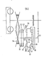
- a variator 10 of the transmission mechanism shown in Figure 1 has " n input sheave 11, and output sheave 12 and a flexible drive band 13 interconnecting the two sheaves.
- the drive band is frictionally engaged with the conventional conical sheave surfaces and provides a driving connection between the two sheaves.
- the band may be in the form of a belt or of a chain with transverse pins for frictional engagement with the sheaves.
- the effective diameters of the sheaves are variable in a conventional way to vary the drive ratio of the variator.
- the input sheave 11 is mounted on and driven by an input shaft 14 and the output sheave 12 is mounted on and drives a variator output shaft 15.
- An output shaft 16 of the transmission mechanism as a whole is co-axial with the input shaft 14 and can be selectively connected to the input shaft 14 by means of a direct drive clutch 17.
- An epicyclic gearset 31 is arranged to be co-axial with the variator output sheave 12 and has its sun gear 18 permanently connected to and driven by the variator output shaft 15.
- the epicyclic gearset- also incorporates a planet carrier 19 carrying the usual planet gears which mesn wich the sun gear 18 and an annulus gear 20 which also meshes with the planet gears. Further details of the epicyclic gearset and its operation will be described subsequently.
- An output shaft 21 from the epicyclic gearset 31 carries a gear 22 which meshes with an idler gear 23 which in turn meshes with a gear 24 on the output shaft 16.
- the gearing 22. 23; 24 is a reduction gearing between the epicyclic gearset output shaft 21 and the output shaft 16. The reduction ratio of this gearing is the same as the highest usable step-up ratio of the variator 10 for reasons which will be described subsequently.
- a first brake 25 is operable to brake the planet carrier 19 to the trans-Lission bsing 26.
- a sec 1 brake 27 is oper ple to brake the annulus 20 to the casing 26.
- a clutch 28 is operable to clutch the planet carrier 19 to shaft 21 and a clutch 29 is operable to clutch the annulus 20 to the shaft 21.
- the input shaft 14 is driven from, for example, a prime mover output shaft 30 through a fluid coupling 31.
- the transmission mechanism shown in Figure 1 can be operated in a variety of different modes which will now be described. Firstly, the mode of operation which gives the highest reduction ratio of the transmission mechanism as a whole is achieved when the clutch 17 is disengaged, brake 27 is operated to hold the annulus 20 stationary and the planet carrier 19 is clutched to the shaft 21. In this mode, the variator drives the shaft 15 which in turn drives sun gear 18 so that shaft 21 is driven at the planetary reduction ratio and drives the output shaft 16 through the reduction gearing 22, 23, 24.
- the reduction ratio achieved is the product of the epicyclic reduction ratio and the variator ratio. This can vary from a very large reduction when the variator is set to its maximum reduction ration to a much lower reduction when the variator is set to its maximum step-up ratio.
- a second mode of operation is obtained by leaving clutch 17 disengaged, clutching planet carrier 19 to the shaft 21 by clutch 28 and also clutching annulus 20 to the shaft 21 by clutch 29. Brakes 25 and 26 remain released. In this situation, the planetary gearset is locked up and provides a direct drive.
- the overall drive ratio of the transmission mechanism is the product of the variator ratio and the reduction gearing 22, 23, 24.
- the ratios are selected cc that the maximum reduction ratio available in this second mode of operation corresponds generally to the smallest reduction ratio (highest ratio) in the first mode of operation. A small overlap of ratios may be desirable. In this way, a continuous range of ratios is available.
- the planet carrier 19 is held stationary by means of the brake 25 while the annulus 20 is clutched to the shaft 21 by means of clutch 29.
- the direct drive clutch 17 is of course disengaged.
- the range of ratios available in the variator will be from a 2:1 reduction to a 2:1 step-up ratie (i.e., a ratio of 0.5;1).
- the reduction ratio of the gearing 22, 23, 24 should also be 2:1.
- the maximum reduction ratio of the variator is 2:1 and not 1.25:1 there is some overlap between the ratios available in the first and second modes of operation and with a suitable control system this can be used to prevent hunting between the two modes of operation when the required ratio varies slightly either side of 2.5:1.
- a compound epicyclic gearset 41 incorporates a first sun gear 42 with corresponding planet carrier 43, planet gears 44 and annulus 45 and also incorporates a second sun gear 46 with corresponding planet carrier 47, planet geale 40 and annulus 49, Annulus 45 and planet carrier 47 are permanently connected to each other and to an output shaft 51 of the planetary gearset.
- the two sun gears 42 and 46 are permanently connected together and are also connectable by means of a clutch 52 to a sleeve 53 which forms the output from the output sheave 54 of the variator.
- a second clutch 55 can connect annulus 49 to the variator output sheave
- a brake 56 is provided to selectively hold the planet carrier 43 Rtationary. T ne operation of this compound planetary gearset to achieve the first and second modes of operation and reverse drive is simplified in that only two clutches and one brake are required as opposed to the requirement for two clutches and two brakes in the arrangement of Figure 1.
Landscapes
- Engineering & Computer Science (AREA)
- General Engineering & Computer Science (AREA)
- Mechanical Engineering (AREA)
- Transmission Devices (AREA)
Applications Claiming Priority (2)
| Application Number | Priority Date | Filing Date | Title |
|---|---|---|---|
| GB252378 | 1978-01-21 | ||
| GB252378 | 1978-01-21 |
Publications (3)
| Publication Number | Publication Date |
|---|---|
| EP0003408A1 true EP0003408A1 (de) | 1979-08-08 |
| EP0003408B1 EP0003408B1 (de) | 1981-12-30 |
| EP0003408B2 EP0003408B2 (de) | 1985-04-03 |
Family
ID=9741061
Family Applications (1)
| Application Number | Title | Priority Date | Filing Date |
|---|---|---|---|
| EP79300080A Expired EP0003408B2 (de) | 1978-01-21 | 1979-01-17 | Stufenlos regelbares Getriebe |
Country Status (4)
| Country | Link |
|---|---|
| US (1) | US4290320A (de) |
| EP (1) | EP0003408B2 (de) |
| CA (1) | CA1098340A (de) |
| DE (1) | DE2961626D1 (de) |
Cited By (3)
| Publication number | Priority date | Publication date | Assignee | Title |
|---|---|---|---|---|
| EP0942199A3 (de) * | 1998-03-13 | 1999-09-29 | Isuzu Motors Limited | Stufenlos regelbares Toroidgetriebe |
| DE102008039254A1 (de) | 2008-08-20 | 2010-02-25 | Megainpharm Gmbh | Arzneimittel |
| EP2969631A4 (de) * | 2013-03-15 | 2016-11-16 | Allison Transm Inc | Variatorüberbrückungskupplung |
Families Citing this family (52)
| Publication number | Priority date | Publication date | Assignee | Title |
|---|---|---|---|---|
| GB2045368B (en) * | 1978-12-09 | 1982-12-08 | Gkn Transmissions Ltd | Continuously variable ratio transmission |
| JPS5666557A (en) * | 1979-10-30 | 1981-06-05 | Aisin Warner Ltd | Speed change gear |
| DE2944928C2 (de) * | 1979-11-07 | 1985-10-31 | Volkswagenwerk Ag, 3180 Wolfsburg | Motor-Getriebeanordnung für Fahrzeuge, insbesondere Personenkraftfahrzeuge |
| NL8105451A (nl) * | 1981-12-03 | 1983-07-01 | Doornes Transmissie Bv | Transmissie, in het bijzonder voor een voertuig, voorzien van een hydrodynamische koppelomvormer. |
| FR2522100B1 (fr) * | 1982-02-22 | 1987-04-24 | Valeo | Transmission entre une prise de mouvement et un arbre recepteur, notamment pour vehicule automobile |
| DE3212769A1 (de) * | 1982-04-06 | 1983-10-06 | Volkswagenwerk Ag | Getriebeanordnung |
| US4489621A (en) * | 1982-09-28 | 1984-12-25 | Borg-Warner Corporation | Dual wet output clutch for power selection in a continuously variable transmission |
| US4489622A (en) * | 1982-09-28 | 1984-12-25 | Borg-Warner Corporation | Dual wet output clutch for power selection in a continuously variable transmission |
| DE3241789C2 (de) * | 1982-11-11 | 1985-08-08 | Ford-Werke AG, 5000 Köln | Getriebeaggregat für Fahrzeuge, insbesondere für Kraftfahrzeuge mit Frontantrieb |
| JPS59110954A (ja) * | 1982-12-13 | 1984-06-27 | Toyota Motor Corp | 無段変速装置 |
| JPS6037455A (ja) * | 1983-08-10 | 1985-02-26 | Toyota Motor Corp | 車両用無段変速装置 |
| DE3424856A1 (de) * | 1984-07-06 | 1986-01-16 | Ford-Werke AG, 5000 Köln | Getriebeaggregat fuer kraftfahrzeuge mit einem stufenlos regelbaren zugorgangetriebe |
| AT383315B (de) * | 1984-10-12 | 1987-06-25 | Steyr Daimler Puch Ag | Antriebsanordnung fuer kraftfahrzeuge mit zwei getriebenen achsen |
| US4672863A (en) * | 1985-04-17 | 1987-06-16 | Toyota Jidosha Kabushiki Kaisha | Method and apparatus for controlling power transmission system in an automotive vehicle |
| GB8522747D0 (en) * | 1985-09-13 | 1985-10-16 | Fellows T G | Transmission systems |
| US4644820A (en) * | 1986-02-03 | 1987-02-24 | General Motors Corporation | Geared-neutral continuously variable transmission |
| DE3769390D1 (de) * | 1986-07-21 | 1991-05-23 | Siemens Ag | Verfahren zum bilden von datenblocksicherungsinformationen fuer serielle datenbitfolgen mittels zyklischer binaercodes. |
| US4913003A (en) * | 1986-09-18 | 1990-04-03 | Tervola Pentti J | Stepless transmission |
| US4836049A (en) * | 1987-12-07 | 1989-06-06 | Ford Motor Company | Continually variable transmission having fixed ratio and variable ratio mechanisms |
| US4856369A (en) * | 1987-12-28 | 1989-08-15 | Ford Motor Company | Continually variable transmission having torque regeneration operating mode |
| US4876920A (en) * | 1988-07-07 | 1989-10-31 | Ford Motor Company | Dual range infinitely variable transmission |
| US5011458A (en) * | 1988-11-09 | 1991-04-30 | Kumm Industries, Inc. | Continuously variable transmission using planetary gearing with regenerative torque transfer and employing belt slip to measure and control pulley torque |
| US5230669A (en) * | 1989-01-30 | 1993-07-27 | Tervola Pentti J | Stepless transmission with disconnectable neutral seeking mechanism |
| US4946429A (en) * | 1989-08-14 | 1990-08-07 | General Motors Corporation | Power transmission with a continuously variable speed range |
| JPH051756A (ja) * | 1991-03-29 | 1993-01-08 | Mazda Motor Corp | 無段変速機 |
| JP3612773B2 (ja) * | 1995-03-24 | 2005-01-19 | アイシン・エィ・ダブリュ株式会社 | 無段変速機 |
| DE69618367T2 (de) * | 1995-03-24 | 2002-11-14 | Aisin Aw Co | Stufenloses Getriebe |
| DE19521486B4 (de) * | 1995-06-13 | 2007-06-21 | Claas Kgaa Mbh | Stellkoppelgetriebe |
| JP3475613B2 (ja) * | 1995-11-24 | 2003-12-08 | アイシン・エィ・ダブリュ株式会社 | 無段変速機 |
| DE19654695B4 (de) * | 1995-12-30 | 2012-01-19 | Hyundai Motor Co. | Stufenloses Getriebe |
| US5720686A (en) * | 1996-06-24 | 1998-02-24 | National Science Council | Transmission system |
| US5853343A (en) * | 1996-09-05 | 1998-12-29 | Ford Global Technologies, Inc. | Dual mode continually variable transmission |
| DE19728610A1 (de) * | 1997-07-04 | 1999-02-04 | Zahnradfabrik Friedrichshafen | Stufenloses Getriebe |
| DE19728611A1 (de) * | 1997-07-04 | 1999-02-04 | Zahnradfabrik Friedrichshafen | Stufenloses Getriebe |
| US6106428A (en) * | 1998-03-23 | 2000-08-22 | Ford Global Technologies, Inc. | Compact dual mode continually variable transmission |
| USRE38887E1 (en) * | 1998-08-06 | 2005-11-22 | Veritran, Inc. | Infinitely variable epicyclic transmissions |
| MXPA01001304A (es) | 1998-08-06 | 2005-09-08 | Veritran Inc | Transmisiones epiciclicas infinitamente variables. |
| DE19858553A1 (de) | 1998-12-18 | 2000-06-21 | Zahnradfabrik Friedrichshafen | Stufenlos verstellbares Fahrzeuggetriebe |
| US6742618B2 (en) * | 2000-03-07 | 2004-06-01 | Arctic Cat, Inc. | Snowmobile planetary drive system |
| US6561942B2 (en) * | 2001-06-11 | 2003-05-13 | General Motors Corporation | Dual mode variable ratio transmission |
| JP2006132595A (ja) * | 2004-11-02 | 2006-05-25 | Nissan Motor Co Ltd | 車両用自動変速機 |
| US20110165986A1 (en) * | 2010-07-19 | 2011-07-07 | Ford Global Technologies, Llc | Transmission Producing Continuously Speed Ratios |
| US9228650B2 (en) * | 2010-08-16 | 2016-01-05 | Allison Transmission, Inc. | Gear scheme for infinitely variable transmission |
| US9085225B2 (en) | 2012-01-23 | 2015-07-21 | Dennis Ray Halwes | Infinitely variable transmission |
| DE102013226292B4 (de) * | 2012-12-19 | 2021-12-23 | Schaeffler Technologies AG & Co. KG | Mehrbereich-CVT |
| EP2971864B1 (de) * | 2013-03-15 | 2021-01-13 | Allison Transmission, Inc. | Stufenlose getriebearchitektur mit leistungsverzweigung |
| KR101459462B1 (ko) * | 2013-05-28 | 2014-11-07 | 현대자동차 주식회사 | 차량용 무단 변속기 |
| US20150087464A1 (en) * | 2013-09-23 | 2015-03-26 | GM Global Technology Operations LLC | Two mode continuously variable transmission |
| US10221927B2 (en) * | 2014-08-14 | 2019-03-05 | Ford Global Technologies, Llc | Continuously variable transmission with overdrive |
| JP6241445B2 (ja) * | 2015-04-17 | 2017-12-06 | トヨタ自動車株式会社 | 動力伝達装置の制御装置 |
| US20180320768A1 (en) * | 2017-05-05 | 2018-11-08 | GM Global Technology Operations LLC | Multi-mode continuously-variable transmission |
| US10608497B2 (en) | 2017-12-18 | 2020-03-31 | Caterpillar Inc. | Electric power system having energy storage with motor-charged flywheel |
Citations (4)
| Publication number | Priority date | Publication date | Assignee | Title |
|---|---|---|---|---|
| GB1128694A (en) * | 1966-04-06 | 1968-10-02 | Deere & Co | Combined variable-speed and planetary drive |
| DE1625030A1 (de) * | 1966-04-08 | 1970-02-05 | Deere & Co | Umlaufraederwechselgetriebe,insbesondere fuer landwirtschaftlich nutzbare Motorfahrzeuge |
| DE1751511A1 (de) * | 1968-06-11 | 1971-03-18 | Hans Bergmann | Abdichtung fuer laengsverschiebbare und drehbare Duesenrohre bei Russblaesern |
| DE2531614A1 (de) * | 1975-07-15 | 1977-02-03 | August Paul Dipl Ing Dr H C | Stufenloser drehmomentenwandler |
Family Cites Families (6)
| Publication number | Priority date | Publication date | Assignee | Title |
|---|---|---|---|---|
| US2745297A (en) * | 1953-01-28 | 1956-05-15 | Budd W Andrus | Reversible speed changer |
| US3251243A (en) * | 1962-05-21 | 1966-05-17 | Deere & Co | Variable-speed transmission combined with planetary drive |
| FR1440883A (fr) * | 1964-05-02 | 1966-06-03 | Zahnradfabrik Friedrichshafen | Système de transmission |
| US3503279A (en) * | 1967-06-01 | 1970-03-31 | Sievert Electric Co | Variable speed power transmission mechanism |
| SU428973A1 (ru) * | 1971-03-31 | 1974-05-25 | Трансмиссия гусеничной машины | |
| US3943780A (en) * | 1974-07-18 | 1976-03-16 | Hermann Klaue | Planetary gear drive with power distribution |
-
1979
- 1979-01-17 EP EP79300080A patent/EP0003408B2/de not_active Expired
- 1979-01-17 DE DE7979300080T patent/DE2961626D1/de not_active Expired
- 1979-01-19 CA CA320,000A patent/CA1098340A/en not_active Expired
- 1979-01-24 US US06/005,978 patent/US4290320A/en not_active Expired - Lifetime
Patent Citations (4)
| Publication number | Priority date | Publication date | Assignee | Title |
|---|---|---|---|---|
| GB1128694A (en) * | 1966-04-06 | 1968-10-02 | Deere & Co | Combined variable-speed and planetary drive |
| DE1625030A1 (de) * | 1966-04-08 | 1970-02-05 | Deere & Co | Umlaufraederwechselgetriebe,insbesondere fuer landwirtschaftlich nutzbare Motorfahrzeuge |
| DE1751511A1 (de) * | 1968-06-11 | 1971-03-18 | Hans Bergmann | Abdichtung fuer laengsverschiebbare und drehbare Duesenrohre bei Russblaesern |
| DE2531614A1 (de) * | 1975-07-15 | 1977-02-03 | August Paul Dipl Ing Dr H C | Stufenloser drehmomentenwandler |
Cited By (4)
| Publication number | Priority date | Publication date | Assignee | Title |
|---|---|---|---|---|
| EP0942199A3 (de) * | 1998-03-13 | 1999-09-29 | Isuzu Motors Limited | Stufenlos regelbares Toroidgetriebe |
| DE102008039254A1 (de) | 2008-08-20 | 2010-02-25 | Megainpharm Gmbh | Arzneimittel |
| EP2969631A4 (de) * | 2013-03-15 | 2016-11-16 | Allison Transm Inc | Variatorüberbrückungskupplung |
| US10145471B2 (en) | 2013-03-15 | 2018-12-04 | Allison Transmission, Inc. | Variator bypass clutch |
Also Published As
| Publication number | Publication date |
|---|---|
| EP0003408B2 (de) | 1985-04-03 |
| EP0003408B1 (de) | 1981-12-30 |
| US4290320A (en) | 1981-09-22 |
| CA1098340A (en) | 1981-03-31 |
| DE2961626D1 (en) | 1982-02-18 |
Similar Documents
| Publication | Publication Date | Title |
|---|---|---|
| EP0003408A1 (de) | Stufenlos regelbares Getriebe | |
| US6045477A (en) | Continuously variable multi-range powertrain with a geared neutral | |
| US4589303A (en) | Continuously variable transmission with synchronous shift | |
| US4608885A (en) | Multi-range continuously variable power transmission | |
| US3381546A (en) | Power transmitting mechanism | |
| US5853343A (en) | Dual mode continually variable transmission | |
| KR100262593B1 (ko) | 차량용 무단 변속장치 | |
| EP0719961A2 (de) | Mehrgängiges Automatikgetriebe für ein Motorfahrzeug | |
| EP0322574B1 (de) | Stufenloses Getriebe mit Wirkungsweise zur Drehmomentenregenerierung | |
| GB2144814A (en) | Driving device including continuously variable transmission | |
| GB2213215A (en) | Continuously variable transmission having fixed ratio and variable ratio mechanisms | |
| US4136581A (en) | Continuously adjustable transmission with two speed ranges | |
| EP0105515A1 (de) | Getriebe mit Leistungsverzweigung | |
| US5888161A (en) | All wheel drive continuously variable transmission having dual mode operation | |
| GB2023752A (en) | Variable-speed gearbox | |
| US3534632A (en) | Hydromechanical transmission having full hydrostatic and output split power drives | |
| US4363247A (en) | Transmission with a first-stage hydrostatic mode and two hydromechanical stages | |
| EP0173482A1 (de) | Stufenloses Getriebe mit Gleichlaufübergang und erweitertem Übersetzungsbereich | |
| US3640153A (en) | Four-speed ratio power transmission mechanism having simple planetary gear units | |
| EP0096980A1 (de) | Kraftübertragung mit stufenlos veränderbarem Übersetzungsverhältnis mit dauernd laufendem Riemen und mit hydrodynamischer Kupplung | |
| US4867011A (en) | Four speed planetary gear transmission having three driving modes | |
| US3367211A (en) | Transmission | |
| KR100256587B1 (ko) | 차량용 무단 변속기 | |
| US3000235A (en) | Planetary transmission | |
| KR100260149B1 (ko) | 차량용 무단 변속장치 |
Legal Events
| Date | Code | Title | Description |
|---|---|---|---|
| PUAI | Public reference made under article 153(3) epc to a published international application that has entered the european phase |
Free format text: ORIGINAL CODE: 0009012 |
|
| AK | Designated contracting states |
Designated state(s): DE FR GB IT NL SE |
|
| 17P | Request for examination filed | ||
| RAP1 | Party data changed (applicant data changed or rights of an application transferred) |
Owner name: P.I.V. ANTRIEB WERNER REIMERS KOMMANDITGESELLSCHAF |
|
| ITF | It: translation for a ep patent filed |
Owner name: ING. C. GREGORJ S.P.A. |
|
| GRAA | (expected) grant |
Free format text: ORIGINAL CODE: 0009210 |
|
| AK | Designated contracting states |
Designated state(s): DE FR GB IT NL SE |
|
| REF | Corresponds to: |
Ref document number: 2961626 Country of ref document: DE Date of ref document: 19820218 |
|
| RAP2 | Party data changed (patent owner data changed or rights of a patent transferred) |
Owner name: P.I.V. ANTRIEB WERNER REIMERS GMBH & CO KG |
|
| PLBI | Opposition filed |
Free format text: ORIGINAL CODE: 0009260 |
|
| 26 | Opposition filed |
Opponent name: VAN DOORNE'S TRANSMISSIE B.V. Effective date: 19820928 |
|
| ITF | It: translation for a ep patent filed |
Owner name: ING. C. GREGORJ S.P.A. |
|
| PUAH | Patent maintained in amended form |
Free format text: ORIGINAL CODE: 0009272 |
|
| STAA | Information on the status of an ep patent application or granted ep patent |
Free format text: STATUS: PATENT MAINTAINED AS AMENDED |
|
| 27A | Patent maintained in amended form | ||
| AK | Designated contracting states |
Kind code of ref document: B2 Designated state(s): DE FR GB IT NL SE |
|
| ET2 | Fr: translation filed ** revision of the translation of the modified patent after opposition | ||
| NLR2 | Nl: decision of opposition | ||
| NLR3 | Nl: receipt of modified translations in the netherlands language after an opposition procedure | ||
| PGFP | Annual fee paid to national office [announced via postgrant information from national office to epo] |
Ref country code: FR Payment date: 19901120 Year of fee payment: 13 |
|
| PGFP | Annual fee paid to national office [announced via postgrant information from national office to epo] |
Ref country code: GB Payment date: 19910115 Year of fee payment: 13 |
|
| PGFP | Annual fee paid to national office [announced via postgrant information from national office to epo] |
Ref country code: SE Payment date: 19910117 Year of fee payment: 13 |
|
| PGFP | Annual fee paid to national office [announced via postgrant information from national office to epo] |
Ref country code: DE Payment date: 19910129 Year of fee payment: 13 |
|
| ITTA | It: last paid annual fee | ||
| PGFP | Annual fee paid to national office [announced via postgrant information from national office to epo] |
Ref country code: NL Payment date: 19910131 Year of fee payment: 13 |
|
| PG25 | Lapsed in a contracting state [announced via postgrant information from national office to epo] |
Ref country code: DE Effective date: 19911129 |
|
| PG25 | Lapsed in a contracting state [announced via postgrant information from national office to epo] |
Ref country code: GB Effective date: 19920117 |
|
| PG25 | Lapsed in a contracting state [announced via postgrant information from national office to epo] |
Ref country code: SE Effective date: 19920118 |
|
| PG25 | Lapsed in a contracting state [announced via postgrant information from national office to epo] |
Ref country code: NL Effective date: 19920801 |
|
| NLV4 | Nl: lapsed or anulled due to non-payment of the annual fee | ||
| REG | Reference to a national code |
Ref country code: GB Ref legal event code: PCNP |
|
| PG25 | Lapsed in a contracting state [announced via postgrant information from national office to epo] |
Ref country code: FR Effective date: 19920930 |
|
| REG | Reference to a national code |
Ref country code: FR Ref legal event code: ST |
|
| EUG | Se: european patent has lapsed |
Ref document number: 79300080.3 Effective date: 19920806 |