EP0003293A1 - Heizverfahren mit einer Absorptionswärmepumpenanlage - Google Patents
Heizverfahren mit einer Absorptionswärmepumpenanlage Download PDFInfo
- Publication number
- EP0003293A1 EP0003293A1 EP79100084A EP79100084A EP0003293A1 EP 0003293 A1 EP0003293 A1 EP 0003293A1 EP 79100084 A EP79100084 A EP 79100084A EP 79100084 A EP79100084 A EP 79100084A EP 0003293 A1 EP0003293 A1 EP 0003293A1
- Authority
- EP
- European Patent Office
- Prior art keywords
- absorber
- heat exchanger
- heating
- refrigerant
- expeller
- Prior art date
- Legal status (The legal status is an assumption and is not a legal conclusion. Google has not performed a legal analysis and makes no representation as to the accuracy of the status listed.)
- Withdrawn
Links
- 238000000034 method Methods 0.000 title claims abstract description 25
- 238000010438 heat treatment Methods 0.000 title claims abstract description 21
- 238000010521 absorption reaction Methods 0.000 title claims abstract description 14
- 238000009434 installation Methods 0.000 title 1
- 239000006096 absorbing agent Substances 0.000 claims abstract description 29
- 239000003507 refrigerant Substances 0.000 claims description 38
- 239000003546 flue gas Substances 0.000 claims description 10
- UGFAIRIUMAVXCW-UHFFFAOYSA-N Carbon monoxide Chemical compound [O+]#[C-] UGFAIRIUMAVXCW-UHFFFAOYSA-N 0.000 claims description 5
- 239000007788 liquid Substances 0.000 claims description 5
- 239000007789 gas Substances 0.000 claims description 3
- 239000003921 oil Substances 0.000 claims description 3
- 239000004449 solid propellant Substances 0.000 claims description 3
- 238000005422 blasting Methods 0.000 claims description 2
- 230000003068 static effect Effects 0.000 claims description 2
- 239000000243 solution Substances 0.000 claims 3
- 239000003795 chemical substances by application Substances 0.000 claims 1
- 230000001419 dependent effect Effects 0.000 claims 1
- 238000002347 injection Methods 0.000 claims 1
- 239000007924 injection Substances 0.000 claims 1
- VOPWNXZWBYDODV-UHFFFAOYSA-N Chlorodifluoromethane Chemical compound FC(F)Cl VOPWNXZWBYDODV-UHFFFAOYSA-N 0.000 description 13
- ZUHZGEOKBKGPSW-UHFFFAOYSA-N tetraglyme Chemical compound COCCOCCOCCOCCOC ZUHZGEOKBKGPSW-UHFFFAOYSA-N 0.000 description 10
- XLYOFNOQVPJJNP-UHFFFAOYSA-N water Substances O XLYOFNOQVPJJNP-UHFFFAOYSA-N 0.000 description 8
- QGZKDVFQNNGYKY-UHFFFAOYSA-N Ammonia Chemical compound N QGZKDVFQNNGYKY-UHFFFAOYSA-N 0.000 description 6
- 230000008569 process Effects 0.000 description 6
- 239000002904 solvent Substances 0.000 description 6
- 239000000126 substance Substances 0.000 description 6
- AMXOYNBUYSYVKV-UHFFFAOYSA-M lithium bromide Chemical compound [Li+].[Br-] AMXOYNBUYSYVKV-UHFFFAOYSA-M 0.000 description 4
- 239000000463 material Substances 0.000 description 4
- 239000000203 mixture Substances 0.000 description 4
- 229910021529 ammonia Inorganic materials 0.000 description 3
- 230000006835 compression Effects 0.000 description 3
- 238000007906 compression Methods 0.000 description 3
- 238000001816 cooling Methods 0.000 description 3
- 238000010586 diagram Methods 0.000 description 3
- 238000001704 evaporation Methods 0.000 description 3
- 230000008020 evaporation Effects 0.000 description 3
- LCGLNKUTAGEVQW-UHFFFAOYSA-N Dimethyl ether Chemical compound COC LCGLNKUTAGEVQW-UHFFFAOYSA-N 0.000 description 2
- 238000009833 condensation Methods 0.000 description 2
- 230000005494 condensation Effects 0.000 description 2
- 230000007797 corrosion Effects 0.000 description 2
- 238000005260 corrosion Methods 0.000 description 2
- 238000000354 decomposition reaction Methods 0.000 description 2
- 238000005516 engineering process Methods 0.000 description 2
- VCRNFKKHEIEHCS-UHFFFAOYSA-N 2-[2-[2-(2-hydroxyethoxy)ethoxy]ethoxy]ethanol;methoxymethane Chemical compound COC.OCCOCCOCCOCCO VCRNFKKHEIEHCS-UHFFFAOYSA-N 0.000 description 1
- 239000012080 ambient air Substances 0.000 description 1
- 238000009835 boiling Methods 0.000 description 1
- 230000008859 change Effects 0.000 description 1
- 230000002860 competitive effect Effects 0.000 description 1
- 238000010276 construction Methods 0.000 description 1
- 230000017525 heat dissipation Effects 0.000 description 1
- 230000006872 improvement Effects 0.000 description 1
- 229920001223 polyethylene glycol Polymers 0.000 description 1
- 238000001556 precipitation Methods 0.000 description 1
- 230000000750 progressive effect Effects 0.000 description 1
- 150000003839 salts Chemical class 0.000 description 1
- 229920006395 saturated elastomer Polymers 0.000 description 1
- 239000011877 solvent mixture Substances 0.000 description 1
- UWHCKJMYHZGTIT-UHFFFAOYSA-N tetraethylene glycol Chemical compound OCCOCCOCCOCCO UWHCKJMYHZGTIT-UHFFFAOYSA-N 0.000 description 1
- 230000001988 toxicity Effects 0.000 description 1
- 231100000419 toxicity Toxicity 0.000 description 1
- 238000011144 upstream manufacturing Methods 0.000 description 1
Images


Classifications
-
- F—MECHANICAL ENGINEERING; LIGHTING; HEATING; WEAPONS; BLASTING
- F25—REFRIGERATION OR COOLING; COMBINED HEATING AND REFRIGERATION SYSTEMS; HEAT PUMP SYSTEMS; MANUFACTURE OR STORAGE OF ICE; LIQUEFACTION SOLIDIFICATION OF GASES
- F25B—REFRIGERATION MACHINES, PLANTS OR SYSTEMS; COMBINED HEATING AND REFRIGERATION SYSTEMS; HEAT PUMP SYSTEMS
- F25B15/00—Sorption machines, plants or systems, operating continuously, e.g. absorption type
- F25B15/02—Sorption machines, plants or systems, operating continuously, e.g. absorption type without inert gas
-
- F—MECHANICAL ENGINEERING; LIGHTING; HEATING; WEAPONS; BLASTING
- F25—REFRIGERATION OR COOLING; COMBINED HEATING AND REFRIGERATION SYSTEMS; HEAT PUMP SYSTEMS; MANUFACTURE OR STORAGE OF ICE; LIQUEFACTION SOLIDIFICATION OF GASES
- F25B—REFRIGERATION MACHINES, PLANTS OR SYSTEMS; COMBINED HEATING AND REFRIGERATION SYSTEMS; HEAT PUMP SYSTEMS
- F25B25/00—Machines, plants or systems, using a combination of modes of operation covered by two or more of the groups F25B1/00 - F25B23/00
- F25B25/02—Compression-sorption machines, plants, or systems
-
- F—MECHANICAL ENGINEERING; LIGHTING; HEATING; WEAPONS; BLASTING
- F25—REFRIGERATION OR COOLING; COMBINED HEATING AND REFRIGERATION SYSTEMS; HEAT PUMP SYSTEMS; MANUFACTURE OR STORAGE OF ICE; LIQUEFACTION SOLIDIFICATION OF GASES
- F25B—REFRIGERATION MACHINES, PLANTS OR SYSTEMS; COMBINED HEATING AND REFRIGERATION SYSTEMS; HEAT PUMP SYSTEMS
- F25B30/00—Heat pumps
- F25B30/04—Heat pumps of the sorption type
-
- Y—GENERAL TAGGING OF NEW TECHNOLOGICAL DEVELOPMENTS; GENERAL TAGGING OF CROSS-SECTIONAL TECHNOLOGIES SPANNING OVER SEVERAL SECTIONS OF THE IPC; TECHNICAL SUBJECTS COVERED BY FORMER USPC CROSS-REFERENCE ART COLLECTIONS [XRACs] AND DIGESTS
- Y02—TECHNOLOGIES OR APPLICATIONS FOR MITIGATION OR ADAPTATION AGAINST CLIMATE CHANGE
- Y02A—TECHNOLOGIES FOR ADAPTATION TO CLIMATE CHANGE
- Y02A30/00—Adapting or protecting infrastructure or their operation
- Y02A30/27—Relating to heating, ventilation or air conditioning [HVAC] technologies
-
- Y—GENERAL TAGGING OF NEW TECHNOLOGICAL DEVELOPMENTS; GENERAL TAGGING OF CROSS-SECTIONAL TECHNOLOGIES SPANNING OVER SEVERAL SECTIONS OF THE IPC; TECHNICAL SUBJECTS COVERED BY FORMER USPC CROSS-REFERENCE ART COLLECTIONS [XRACs] AND DIGESTS
- Y02—TECHNOLOGIES OR APPLICATIONS FOR MITIGATION OR ADAPTATION AGAINST CLIMATE CHANGE
- Y02B—CLIMATE CHANGE MITIGATION TECHNOLOGIES RELATED TO BUILDINGS, e.g. HOUSING, HOUSE APPLIANCES OR RELATED END-USER APPLICATIONS
- Y02B30/00—Energy efficient heating, ventilation or air conditioning [HVAC]
- Y02B30/62—Absorption based systems
Definitions
- the invention relates to a method for heating with an absorption heat pump system. It is particularly suitable for heating buildings.
- thermodynamic foundations of absorption systems that can be used as cooling or heating systems have been known for around 70 years.
- the absorption heating systems have so far only been used to a modest extent because they are inferior to the compression systems in terms of total costs and were also less advantageous in terms of their dimensions and possible uses.
- the substance pairs ammonia / water and water / lithium bromide are used to a large extent in the absorption heat pumps which have been realized as power devices.
- the use of ammonia in homes is limited by security risks.
- the highest expulsion temperature for the ammonia / water pair is 160 to 180 ° C; excessive corrosion and Decomposition on.
- the water / lithium bromide pair of materials has the disadvantage that the expulsion temperature with regard to decomposition, salt precipitation and corrosion must not exceed 150 ° C. Furthermore, when water is used as the "refrigerant", the evaporation temperature must practically not be below 0 ° C.
- the object of the present invention is now to provide a method for heating, in particular buildings, which is competitive in its overall economy in comparison with both conventional heating systems and with compression heat pumps.
- the implementation of this process should enable savings in primary energy compared to the proven heating technologies.
- the absorber pressure is used in the method for heating buildings with an absorption heat pump system is made independent of the evaporator pressure with the aid of a compressor unit and / or the poor solution returning to the absorber is subcooled in a main heat exchanger to lower temperatures than is possible in the heat exchanger located between the absorber and expeller, and the absorber is operated adiabatically.
- a blasting apparatus is used as the compressor unit and the refrigerant circuit is switched off and the solution circuit is used as a heat transfer system if the evaporator pressure is insufficient depending on the outside temperature.
- the heat exchanger can also be bypassed and the heat can only be given off via the main heat exchanger.
- the flue gases can be cooled with a medium to be heated in a unit downstream of the expeller.
- the flue gas can be used, for example, to evaporate a stream of liquid refrigerant, and the vaporous refrigerant can be used as a motive steam stream in the compressor unit.
- the flue gases can also be cooled directly against heating or process water.
- refrigerant vapor which has been heated as the motive steam for the jet apparatus is removed from the condenser.
- a gear pump is preferably used as the solution pump and a tube with static mixers is used as the adiabatic absorber.
- a suitable working medium for the method according to the invention is e.g. the pair of substances difluoromonochloromethane / tetraethylene glycol dimethyl ether for safe operation in residential buildings.
- the thermal stability, low corrosivity and toxicity of this pair of substances ensure permanent and safe use.
- there is a large boiling point difference between difluoromonochloromethane and tetraethylene glycol dimethyl ether which can be simplified by the cooker or the expeller design because there is no need for rectification.
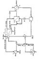
- An absorption heat pump system which works according to the method according to the invention, has an evaporator 1, an expeller 2, a condenser 3, an absorber 4, a heat exchanger 5 in the refrigerant circuit, a compressor unit 6, a further heat exchanger 7 in the solvent circuit, a main heat exchanger 8, if appropriate Unit 9 for flue gas cooling, a solvent pump 10, and various valves shown in the figures in the connecting lines shown.
- the refrigerant vapor leaving the expeller 2 is condensed in the condenser 3 by water used for heating purposes and, if necessary, subcooled.
- the refrigerant condensate occurs after leaving the Condenser 3 in the heat exchanger 5, warms the refrigerant vapor stream emerging from the evaporator 1 and reaches the evaporator 1, where it is supplied with heat from the environment.
- the refrigerant vapor bypass shown between the condenser 3 and the compressor unit 6 opens. Refrigerant vapor thus flows as driving steam through the compressor unit 6 and the refrigerant is brought up to the required absorber pressure . compressed.
- the refrigerant vapor is absorbed by the low-refrigerant solution, which is thereby almost saturated with refrigerant.
- the enriched solution is led from the solution pump 10 through the heat exchanger 7 to the expeller 2.
- the low-refrigerant solution gives off heat to the refrigerant-rich solution.
- the main portion of the heat is withdrawn from the stream of the poor solution via the main heat exchanger 8.
- the design of the system diagram according to FIGS. 1 and 2 is based on the consideration that the system completely guarantees the heating of the building even at very low outside temperatures, although for thermodynamic reasons heat can no longer be pumped and the system thus functions as a pure boiler heating system. As the outside temperature rises, the pumped heat flow constantly and should be on average up to 30% of the heat flow that is supplied to the expeller or cooker 2. Furthermore, the system switching should be as straightforward as possible.
- the expeller 2 is heated by a furnace.
- the highest expeller temperature is not limited by the heat source (e.g. ambient air) but by the chemical stability and corrosiveness of the working mixture, e.g. difluoromonochloromethane / tetraethylene glycol dimethyl ether.
- the bypass to the heat exchanger 5 and thus also to the evaporator 1 is located between the condenser 3 and the absorber 4 so that the system can cover the heating requirements at outside temperatures of around -2 ° C without changing the solvent circulation and without increasing the expeller temperature.
- the bypass exists ( cf. FIG. 2) consisting of a steam and a liquid line and a compressor unit 6.
- a jet apparatus is used as the compressor unit.
- the steam line begins to open as it drops further.
- the refrigerant vapor then flows at high pressure into the compressor unit 6 and compresses the refrigerant stream flowing through the evaporator 1 from the pressure po to a higher pressure p., So that refrigerant is absorbed in the absorber 4 even at these temperatures and the heat is absorbed from the environment has, that is, this circuit shifts the temperature limit below which the system functions as a boiler heater to lower temperatures. Without this measure, the boiler heating heat flow would remain the same The temperature of the expeller 2 rise and the thermal load on the mixture reaches areas in which its stability and corrosiveness have not been investigated and are therefore not guaranteed. If the lower limit of the pressure of the absorber 4 can no longer be reached by opening the steam line, the liquid bypass is opened and the system then functions as a boiler heater. The bypasses of the heat exchanger 7 are also opened, as a result of which the expulsion power is practically transferred directly to the main heat exchanger.
- the heat dissipation in the upstream main heat exchanger 8 can be carried out more easily in terms of apparatus and thermodynamically better than in the absorber 4.
- the refrigerant circuit can be switched off and the solvent circuit can be used as a heat transfer system if the evaporator pressure is insufficient depending on the outside temperature.
- the heat exchanger 7 is preferably bypassed in the heat transfer system operation and the heat is bypassed exclusively via the main heat exchanger 8 submitted.
- the expeller 2 is heated with oil, gas or solid fuels
- the flue gases can be cooled in a unit 9 connected downstream of the expeller 2 with a medium to be heated.
- the flue gas can be used to vaporize a stream of liquid refrigerant, as shown in Figure 1.
- the vaporous refrigerant can be used as motive steam flow in the compressor unit 6.
- FIG. 2 An alternative to this is shown in FIG. 2, in which the usable heat of the flue gases coming from the expeller is transferred directly to water.
- the characters (a) to (n) in FIG. 2 indicate the balance points for the calculations in the example below.
- the evaporation temperature of the refrigerant difluoromonochloromethane is also determined by the above values and Table 1.
- the refrigerant evaporates at -10 ° C and 3.5 bar.
- the pressure drop between the expeller and the condenser is estimated at about 0.8 bar and thus selected as the expeller pressure 25 bar.
- the 25 bar isobars in the h-Bild image of the mixture difluoromonochloromethane / dimethyl ether tetraethylene glycol ( Figure 3) and the
- 176- C isotherms (the highest isotherm that has been experimentally investigated with regard to stability and corrosivity) intersect at a weight concentration of 0.2% by weight.
- the state of the poor solution at the expeller outlet is thus fixed at 25 bar, 176 ° C. and a concentration of 0.2% by weight of difluoromonochloromethane.
- the refrigerant difluoromonochloromethane is absorbed in the poor solution without giving off heat, which increases the temperature and the difluoromonochloromethane concentration in the solution.
- the solution leaves the absorber as a refrigerant-rich solution. Its state point lies on the mixture line of refrigerant vapor / poor solution below the equilibrium line for the absorber pressure, since the equilibrium line cannot be reached for reasons of mass transfer and must not be reached due to the operating behavior of the solvent pump.
- the solution enters the absorber with 20% by weight of refrigerant difluoromonochloromethane and 45 C (Table 1).
- the concentration difference rich / poor solution is chosen to
- Tables 2 and 3 below summarize the process data on which the apparatus dimensioning is based for the selected pair of substances, difluoromonochloromethane / tetraethylene glycol dimethyl ether.
- Table 4 below shows the energy balance for the absorption heat pump circuit according to FIGS. 1 and 2.
Landscapes
- Engineering & Computer Science (AREA)
- Physics & Mathematics (AREA)
- Mechanical Engineering (AREA)
- Thermal Sciences (AREA)
- General Engineering & Computer Science (AREA)
- Sorption Type Refrigeration Machines (AREA)
- Central Heating Systems (AREA)
Applications Claiming Priority (2)
| Application Number | Priority Date | Filing Date | Title |
|---|---|---|---|
| DE2803118 | 1978-01-25 | ||
| DE2803118A DE2803118B2 (de) | 1978-01-25 | 1978-01-25 | Verfahren zur Beheizung mit einer Absorptionswärmepumpenanlage und Vorrichtung zur Durchführung des Verfahrens |
Publications (1)
| Publication Number | Publication Date |
|---|---|
| EP0003293A1 true EP0003293A1 (de) | 1979-08-08 |
Family
ID=6030317
Family Applications (1)
| Application Number | Title | Priority Date | Filing Date |
|---|---|---|---|
| EP79100084A Withdrawn EP0003293A1 (de) | 1978-01-25 | 1979-01-12 | Heizverfahren mit einer Absorptionswärmepumpenanlage |
Country Status (9)
| Country | Link |
|---|---|
| US (1) | US4314668A (da) |
| EP (1) | EP0003293A1 (da) |
| JP (1) | JPS54112540A (da) |
| AT (1) | ATA51679A (da) |
| DE (1) | DE2803118B2 (da) |
| DK (1) | DK7479A (da) |
| ES (1) | ES477034A1 (da) |
| GR (1) | GR64470B (da) |
| NO (1) | NO790089L (da) |
Cited By (4)
| Publication number | Priority date | Publication date | Assignee | Title |
|---|---|---|---|---|
| EP0039545A3 (en) * | 1980-05-03 | 1982-09-22 | Lucas Industries Public Limited Company | An absorption cycle heat pump |
| WO1987006284A1 (fr) * | 1986-04-17 | 1987-10-22 | Tch Thermo-Consulting-Heidelberg Gmbh | Systeme pour la recuperation de la chaleur perdue contenue dans l'air d'evacuation provenant des sechoirs pour machines a papier |
| EP0781969A3 (de) * | 1995-11-22 | 1997-12-10 | SOLVIS Solarsysteme GmbH | Solaranlage mit Zahnradpumpe |
| CN104359246A (zh) * | 2014-11-28 | 2015-02-18 | 天津商业大学 | 涡流分离液体与喷射器引射的co2双温制冷系统 |
Families Citing this family (15)
| Publication number | Priority date | Publication date | Assignee | Title |
|---|---|---|---|---|
| US4532778A (en) * | 1979-11-16 | 1985-08-06 | Rocket Research Company | Chemical heat pump and chemical energy storage system |
| DE2950327C2 (de) * | 1979-12-14 | 1985-10-31 | Stiebel Eltron Gmbh & Co Kg, 3450 Holzminden | Austreiber, insbesondere für eine Absorptionswärmepumpe |
| DE3004197A1 (de) * | 1980-02-06 | 1981-08-27 | GST Gesellschaft für Systemtechnik mbH, 4300 Essen | Verfahren zu rueckgewinnen von waermeenergie, die in den brueden von fuer thermische stofftrennprozesse eingesetzten mehrstufenverdampfern enthalten ist, und vorrichtung zur durchfuehrung des verfahrens |
| DE3018709A1 (de) * | 1980-05-16 | 1981-11-26 | Volkswagenwerk Ag, 3180 Wolfsburg | Parallel-bivalent als absorber-waermepumpe und heizkessel arbeitende zum erwaermen eines waermetraegermediums |
| DE3031033A1 (de) * | 1980-08-16 | 1982-05-06 | Buderus Ag, 6330 Wetzlar | Verfahren und vorrichtung zum betreiben einer monovalent alternativen adsorptionsheizanlage |
| US4485638A (en) * | 1983-02-22 | 1984-12-04 | The United States Of America As Represented By The United States Department Of Energy | Heat exchanger bypass system for an absorption refrigeration system |
| DE3503863A1 (de) * | 1985-02-05 | 1986-08-07 | Georg Prof.Dr. 8000 München Alefeld | Anlage mit einem waerme aufnehmenden und waerme abgebenden prozessteil sowie einem eine absorbereinrichtung enthaltenden waermeversorgungsteil |
| US5216891A (en) * | 1992-06-25 | 1993-06-08 | Gas Research Institute | Solution flows in direct expansion lithium bromide air conditioner/heater |
| ES2140265B1 (es) * | 1996-08-21 | 2000-10-16 | Gas Natural Sdg S A Soc It Per | Ciclo de absorcion de alto rendimiento |
| ES2293384T3 (es) * | 2003-12-22 | 2008-03-16 | Ecoenergy Patent Gmbh | Procedimiento para la conversion de energia termina en energia mecaniza con un dispositivo de expansion a baja presion. |
| US8543245B2 (en) * | 2009-11-20 | 2013-09-24 | Halliburton Energy Services, Inc. | Systems and methods for specifying an operational parameter for a pumping system |
| US8506662B2 (en) * | 2010-04-20 | 2013-08-13 | Honeywell International Inc. | Proactive steam and mist removal system |
| EP2584287B1 (de) * | 2011-10-21 | 2016-01-27 | AGO AG Energie + Anlagen | Kreisprozess zum Betrieb einer Absorptionskältemaschine und Absorptionskältemaschine |
| US9385574B1 (en) * | 2013-06-26 | 2016-07-05 | Ever Source Science & Technology Development Co., Ltd. | Heat transfer fluid based zero-gas-emission power generation |
| CN111141062B (zh) * | 2020-01-21 | 2023-11-03 | 天津商业大学 | 一种太阳能吸收引射复合跨临界co2制冷系统 |
Citations (6)
| Publication number | Priority date | Publication date | Assignee | Title |
|---|---|---|---|---|
| US3041853A (en) * | 1955-11-25 | 1962-07-03 | Harwich Stanley | Refrigerating process and apparatus for the same |
| CH415703A (de) * | 1961-05-25 | 1966-06-30 | Carrier Corp | Anlage zur Erzeugung von Kälte oder von Kälte und Wärme |
| DE2528736A1 (de) * | 1975-06-27 | 1977-01-13 | Hans Dipl Ing Dr Herrmann | Waermepumpe mit thermischem antrieb |
| US4037649A (en) * | 1975-04-04 | 1977-07-26 | Hartka Dale R | Heating and refrigeration system |
| DE2727990A1 (de) * | 1976-06-25 | 1978-01-05 | Exxon France | Verfahren und vorrichtung zur uebertragung von waerme zwischen verhaeltnismaessig kalten und heissen stellen |
| DE2659641A1 (de) * | 1976-12-30 | 1978-07-13 | Christian Dipl Ing Schneider | Gas- oder oelbetriebene heizanlage zur waermeerzeugung |
Family Cites Families (6)
| Publication number | Priority date | Publication date | Assignee | Title |
|---|---|---|---|---|
| US2272871A (en) * | 1938-01-10 | 1942-02-10 | Honeywell Regulator Co | Absorption heating system |
| DE969268C (de) * | 1953-09-08 | 1958-05-14 | Licencia Talalmanyokat | Verfahren und Einrichtung zur Kaelteerzeugung durch Absorption |
| JPS4719666B1 (da) * | 1970-09-25 | 1972-06-05 | ||
| JPS4921699B1 (da) * | 1970-11-28 | 1974-06-03 | ||
| US3717007A (en) * | 1971-04-02 | 1973-02-20 | Arkla Ind | Absorption refrigeration system with multiple generator stages |
| US4171619A (en) * | 1978-03-16 | 1979-10-23 | Clark Silas W | Compressor assisted absorption refrigeration system |
-
1978
- 1978-01-25 DE DE2803118A patent/DE2803118B2/de not_active Withdrawn
- 1978-12-21 GR GR57954A patent/GR64470B/el unknown
-
1979
- 1979-01-08 DK DK7479A patent/DK7479A/da unknown
- 1979-01-11 NO NO790089A patent/NO790089L/no unknown
- 1979-01-12 EP EP79100084A patent/EP0003293A1/de not_active Withdrawn
- 1979-01-20 ES ES477034A patent/ES477034A1/es not_active Expired
- 1979-01-22 JP JP491779A patent/JPS54112540A/ja active Pending
- 1979-01-23 US US06/005,897 patent/US4314668A/en not_active Expired - Lifetime
- 1979-01-24 AT AT0051679A patent/ATA51679A/de not_active IP Right Cessation
Patent Citations (6)
| Publication number | Priority date | Publication date | Assignee | Title |
|---|---|---|---|---|
| US3041853A (en) * | 1955-11-25 | 1962-07-03 | Harwich Stanley | Refrigerating process and apparatus for the same |
| CH415703A (de) * | 1961-05-25 | 1966-06-30 | Carrier Corp | Anlage zur Erzeugung von Kälte oder von Kälte und Wärme |
| US4037649A (en) * | 1975-04-04 | 1977-07-26 | Hartka Dale R | Heating and refrigeration system |
| DE2528736A1 (de) * | 1975-06-27 | 1977-01-13 | Hans Dipl Ing Dr Herrmann | Waermepumpe mit thermischem antrieb |
| DE2727990A1 (de) * | 1976-06-25 | 1978-01-05 | Exxon France | Verfahren und vorrichtung zur uebertragung von waerme zwischen verhaeltnismaessig kalten und heissen stellen |
| DE2659641A1 (de) * | 1976-12-30 | 1978-07-13 | Christian Dipl Ing Schneider | Gas- oder oelbetriebene heizanlage zur waermeerzeugung |
Cited By (5)
| Publication number | Priority date | Publication date | Assignee | Title |
|---|---|---|---|---|
| EP0039545A3 (en) * | 1980-05-03 | 1982-09-22 | Lucas Industries Public Limited Company | An absorption cycle heat pump |
| WO1987006284A1 (fr) * | 1986-04-17 | 1987-10-22 | Tch Thermo-Consulting-Heidelberg Gmbh | Systeme pour la recuperation de la chaleur perdue contenue dans l'air d'evacuation provenant des sechoirs pour machines a papier |
| EP0781969A3 (de) * | 1995-11-22 | 1997-12-10 | SOLVIS Solarsysteme GmbH | Solaranlage mit Zahnradpumpe |
| CN104359246A (zh) * | 2014-11-28 | 2015-02-18 | 天津商业大学 | 涡流分离液体与喷射器引射的co2双温制冷系统 |
| CN104359246B (zh) * | 2014-11-28 | 2017-02-22 | 天津商业大学 | 涡流分离液体与喷射器引射的co2双温制冷系统 |
Also Published As
| Publication number | Publication date |
|---|---|
| DE2803118B2 (de) | 1980-07-31 |
| DE2803118A1 (de) | 1979-07-26 |
| DK7479A (da) | 1979-07-26 |
| ES477034A1 (es) | 1979-06-16 |
| ATA51679A (de) | 1982-09-15 |
| GR64470B (en) | 1980-03-26 |
| NO790089L (no) | 1979-07-26 |
| JPS54112540A (en) | 1979-09-03 |
| US4314668A (en) | 1982-02-09 |
Similar Documents
| Publication | Publication Date | Title |
|---|---|---|
| EP0003293A1 (de) | Heizverfahren mit einer Absorptionswärmepumpenanlage | |
| DE3739831C2 (de) | Verfahren zur Wärmeabsorption durch eine Absorptionskältemaschine und Vorrichtung für die Verwendung als Absorptionskältemaschine | |
| DE2754626C2 (de) | Mit einer Energiequelle relativ niedriger Temperatur, insbesondere Solarenergie, arbeitende Kälteanlage | |
| DE69929477T2 (de) | Einen ammoniakkreislauf und einen kohlendioxidkreislauf kombinierende wärmepumpe | |
| DE2915979A1 (de) | Fuer kuehlbetrieb eingerichtete waermepumpenanlage | |
| DE102013205266A1 (de) | Wärmekraftmaschine und Verfahren zum Betreiben einer Wärmekraftmaschine | |
| DE3225613C2 (de) | Absorptionswärmepumpensystem | |
| DE69510821T2 (de) | Kühl-und/oder heizanlage mit absorptionskreislauf | |
| DE69509870T2 (de) | Wärmeaustauschvorrichtung und verfahren für wärmeaustausch zwischen austreiber und absorber und anwendung derselben in einer wärmepumpe | |
| DE102005032266A1 (de) | Verfahren zum Abführen eines Gases aus einer Wärmepumpe und Wärmepumpe | |
| EP2321590B1 (de) | Kompakte resorptionsmaschine | |
| EP0083933A1 (de) | Arbeitsmedium für Sorptions-Wärmepumpen | |
| DE3049967C1 (de) | Sorptions-Kaelte-Apparat sowie Verfahren zu dessen Betrieb | |
| DE3536953C1 (en) | Resorption-type heat converter installation with two solution circuits | |
| DE69507944T2 (de) | Eine zwischenflüssigkeit verwendende wärmetausch-vorrichtung und -verfahren zum wärmeaustausch zwischen austreiber und absorber und verwendung davon in einer absorptionswärmepumpe | |
| EP0134431A2 (de) | An den Ericsson- Prozess angenähertes thermodynamisches Verfahren | |
| DE19533249C1 (de) | Strömungsmaschine zur Erzeugung mechanischer Arbeit aus Wärmeenergie und ein Verfahren zur Erzeugung mechanischer Arbeit aus Wärmeenergie mit einer solchen Strömungsmaschine | |
| DE102007062343B4 (de) | Verfahren und Anordnung zur Kälteerzeugung nach einem Wasser-Lithiumbromid-Resorptionskälteprozess | |
| EP2762800A1 (de) | Absorptionsanlage zum Heizen oder Kühlen eines Trägermediums | |
| EP1203916A1 (de) | Wärmepumpenheizanlage | |
| DE102010008408B4 (de) | Verfahren zum Betreiben eines Rückkühlkreislaufes mit einem Hybridkühler für eine Anlage mit einer diskontinuierlichen Wärmeabgabe und Vorrichtung hierfür | |
| DE3615375C2 (da) | ||
| DE19500335A1 (de) | Verfahren zur Erzeugung von Kälte und Wärme mit Hilfe einer umkehrosmotisch angetriebenen Sorptionskältemaschine | |
| DE102013203243A1 (de) | Wärmepumpe und Verfahren zum Betreiben einer Wärmepumpe | |
| DE10240659B4 (de) | Verfahren und Vorrichtung zur solarthermischen Kälteerzeugung |
Legal Events
| Date | Code | Title | Description |
|---|---|---|---|
| PUAI | Public reference made under article 153(3) epc to a published international application that has entered the european phase |
Free format text: ORIGINAL CODE: 0009012 |
|
| AK | Designated contracting states |
Designated state(s): BE CH FR GB IT NL SE |
|
| 17P | Request for examination filed | ||
| STAA | Information on the status of an ep patent application or granted ep patent |
Free format text: STATUS: THE APPLICATION IS DEEMED TO BE WITHDRAWN |
|
| 18D | Application deemed to be withdrawn |
Effective date: 19811227 |
|
| RIN1 | Information on inventor provided before grant (corrected) |
Inventor name: OELERT, GERHARD Inventor name: KOHNKE, HANS JUERGEN, DIPL.-ING. Inventor name: JANSSEN, HARALD, DR. |