EP0002524A2 - Koaleszenzelement aus nicht orientierten Fasern - Google Patents
Koaleszenzelement aus nicht orientierten Fasern Download PDFInfo
- Publication number
- EP0002524A2 EP0002524A2 EP78101671A EP78101671A EP0002524A2 EP 0002524 A2 EP0002524 A2 EP 0002524A2 EP 78101671 A EP78101671 A EP 78101671A EP 78101671 A EP78101671 A EP 78101671A EP 0002524 A2 EP0002524 A2 EP 0002524A2
- Authority
- EP
- European Patent Office
- Prior art keywords
- matrix
- mixture
- housing
- fibers
- oil
- Prior art date
- Legal status (The legal status is an assumption and is not a legal conclusion. Google has not performed a legal analysis and makes no representation as to the accuracy of the status listed.)
- Withdrawn
Links
Images

Classifications
-
- B—PERFORMING OPERATIONS; TRANSPORTING
- B01—PHYSICAL OR CHEMICAL PROCESSES OR APPARATUS IN GENERAL
- B01D—SEPARATION
- B01D17/00—Separation of liquids, not provided for elsewhere, e.g. by thermal diffusion
- B01D17/02—Separation of non-miscible liquids
- B01D17/04—Breaking emulsions
- B01D17/045—Breaking emulsions with coalescers
Definitions
- This invention relates generally to fluid mixture separators, and more particularly to a separator having particular utility for separating a water/oil mixture.
- Devices for separating the fluids of a mixture of fluids of different mass densities are used in a wiae variety ot applications. For example, such devices have particular utility in separating oil from water.
- Environmental regulations prohibiting the discharge of oily water into oceans, rivers and streams are becoming ever more stringent.
- Environmental regulations in the U . S . for example prohibit such discharge cf water having an oil content greater than 15 parts per million (PPM).
- PPM parts per million
- Several prior art devices have been developed for separating oil from an oil/water mixture. These include oil/water separators of the gravity type such as coalescing plate separators as well as the in- depth filter type such as those which use disposable paper or fiberglass coalescing matrices.
- a system for separating a mixture of fluids of different densities comprises a fibrous matrix in a housing through which the mixture flows.
- the matrix uses randomly interspersed long fibers of an oleophilic non-corrosive material configured to provide a specified mean porosity along the flow direction.
- FIG. 1 therein is shown a schematic diagram of a preferred embodiment for the fibrous matrix separator system of this invention.
- the system includes a cylindrical housing 10 having an inlet 12 through the lower portion of the housing 10 for receiving the influent mixture.
- the inlet 12 is in flow communication with the bottom of a cylindrical container 16 disposed within the housing 10.
- Container 16 is sealed at its lower end-by a plate 18, and is opened at its upper end.
- a matrix 20 constructed of randomly interspersed long fibers of an oleophilic material selected to be resistant to corrosion by the components of the influent mixture.
- the influent received at the inlet 12 is forced under pressure through the container 16 and fibrous matrix 20 and thereafter exits the top of the container 16.
- the fluid exiting the container 16 flows around the outer wall of the container 16 in the space between the container 16 and housing 10 to the bottom of the housing 10 where the effluent exits through an outlet 22 disposed through lower portion of the housing 10.
- the lighter droplets within the mixture will migrate under Stokes law in D arcy matrix flow within the matrix 20 due to the difference in densities between the components of the mixture.
- the migrating droplets intercept and coalesce on the matrix fibers.
- coalesced droplets flow under shear along the fiber paths to the top of the container 16 and thereafter stream to the top of the mixture within the cylindrical housing 10 where the lighter component of the mixture may be removed suctioning removed by suctioning or drained through the discharge port 24 or by using a skimming device (not shown).
- the fibrous matrix 20 may be manufactured from any non-corrosive, chemically inert material which can be fabricated into long, thin fibers of a specified diameter. This includes all of the metals and plastics which will not be corroded by constituents of the fluid mixture.
- a preferred material which is useful in separating oil from water is stainless steel wool.
- the fibers of the matrix 20 may be randomly interspersed by any known fabrication technique, including knitting or weaving.
- the fibers are packed to a density within the container 16 to provide a specified means porosity along the flow direction.
- the flow direction through the matrix 20 while illustrated as vertical may alternatively be in any orientation desired for the particular system.
- the vertically upward direction of flow is pre- ferred, however, since it assists in the efficient separation of coalesced oil from the fibrous matrix 20 and in its removal from the housing 10.
- the coalescent performance of the fibrous matrix 20 has been analytically and experimentally shown to be dependent on the constituents of the influent, the diameter of the fibers used, the matrix porosity, and the time during which the influent mixture is in contact with the matrix 20. Contact time is determined by the mixture flow rate and the length of the matrix 20.
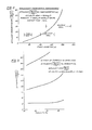
- F ig. 2 therein is shown a graph illustrating effluent concentration as a function of the means porosity along the flow direction through a fibrous matrix 20 disposed in a housing 10 constructed in accordance with the teaching of this invention and used to separate an oil/water mixture.
- an influent containing approximately 1000mg of oil per liter of water was passed through a matrix 20, constructed of fine stainless steel wool mesh.
- the lower porosities exhibited the best coalescing performance.
- Fig. 3 therein is shown a graph illustrating coalescent effectiveness as a function of the diameter of the fibers used to construct the matrix 20.
- the influent concentration was maintained constant at approximately 1,000 milligrams of oil per liter of water
- the contact time was maintained nearly constant varying from 97.5% for the fine stainless wool mesh, to 94.7% for the coarse stainless steel wool mesh.
- the fine stainless steel wool mesh was the most effective in coalescing performance.
- the lower porosities removed the most oil.
- the exposed surface area of the fibrous material used to construct the matrix 20 is a determining factor in separator performance.
- fibrous matrix separator of this invention Another characteristic of the fibrous matrix separator of this invention is that an increase in the velocity of the influent causes an increase in the pressure within the container 16 and a concomitant decrease in contact time and coalescent performance.
- the performance of the separator system my be improved by employing a longer matrix 20 to improve its contact time.
- separator systems constructed in accordance with the teachings of this invention are effective in producing an effluent containing less than 5 milligrams of oil per liter of water from an influent containing approximately 1000 milligrams of oil per liter of oil with oil droplet sizes less than 10 microns ranging between 5 and 11 milligrams per liter of water using number 0000 stainless steel wool as the matrix fiber.
- the separator system of this invention has particular utility as a polishing device. Polishing devices are used in conjuction with other generally larger oil/water separator systems to remove a portion of the oil remaining in the effluent from the larger system. Many such larger systems are ineffective in removing small highly emulsified oil droplets (i.e. those having a means diameter of less than 30 microns).
- the separator system of this invention is adaptable to a wide variety of configurations, influent mixture and flow rates.
- the parameters of the system may be uniquely tailored by proper choice of matrix contact time porosity and fiber size to meet a wide variety of applications.
- Another feature of the separator system of tnis invention is that it maintains a high degree of separation at higher flow rates than can be achieved using a prior art separator exhibiting comparable coalescing performance.
- the fibrous matrix separator system disclosed herein has also demonstrated that it is significantly less susceptible to being plugged by particles of dirt entrained in the influent, since many of the finer particles of dirt are passed through the pores in the matrix 20. Another advantage of the separator system disclosed herein is that the matrix 20 may be removed from the container 16, cleaned and reused.
- the separator system of this invention is also characterized by greater spacial efficiency and a lower pressure drop than is characteristic of systems of the prior art.
- Fig. 1 Various changes could be made in the embodiment shown in Fig. 1 without departing from the scope of the invention.
- the matrix 20 has been depicted as being placed within a cylindrical container 16 within a cylindrical housing 10 it is also possible to devise other structures for housing the matrix 20 as well as to use other shapes for the matrix 20.
Landscapes
- Physics & Mathematics (AREA)
- Thermal Sciences (AREA)
- Chemical & Material Sciences (AREA)
- Chemical Kinetics & Catalysis (AREA)
- Lubricants (AREA)
- Filtering Materials (AREA)
- Removal Of Floating Material (AREA)
- Extraction Or Liquid Replacement (AREA)
Applications Claiming Priority (2)
| Application Number | Priority Date | Filing Date | Title |
|---|---|---|---|
| US86232377A | 1977-12-20 | 1977-12-20 | |
| US862323 | 1977-12-20 |
Publications (2)
| Publication Number | Publication Date |
|---|---|
| EP0002524A2 true EP0002524A2 (de) | 1979-06-27 |
| EP0002524A3 EP0002524A3 (de) | 1979-07-11 |
Family
ID=25338213
Family Applications (1)
| Application Number | Title | Priority Date | Filing Date |
|---|---|---|---|
| EP78101671A Withdrawn EP0002524A3 (de) | 1977-12-20 | 1978-12-14 | Koaleszenzelement aus nicht orientierten Fasern |
Country Status (5)
| Country | Link |
|---|---|
| EP (1) | EP0002524A3 (de) |
| JP (1) | JPS54100571A (de) |
| AU (1) | AU4194578A (de) |
| DK (1) | DK573178A (de) |
| NO (1) | NO784275L (de) |
Cited By (5)
| Publication number | Priority date | Publication date | Assignee | Title |
|---|---|---|---|---|
| EP0067300A2 (de) * | 1981-06-11 | 1982-12-22 | Passavant-Werke Ag | Vorrichtung zur Flüssig-Flüssig-Trennung |
| EP0464532A1 (de) * | 1990-06-29 | 1992-01-08 | Idemitsu Kosan Company Limited | Verfahren zur Rückgewinnung von Schwefel |
| WO1992020422A1 (de) * | 1991-05-24 | 1992-11-26 | Lueth Stefan | Verfahren zum trennen von gemischen von flüssigkeiten unterschiedlicher dichte und adhäsion gegenüber nicht saugenden feststoffoberflächen |
| KR20040024041A (ko) * | 2002-09-12 | 2004-03-20 | 이상수 | 분자력을이용한 에멀전의 유수분리방법 |
| WO2015187917A1 (en) * | 2014-06-04 | 2015-12-10 | Siemens Energy, Inc. | Packed polymer fibers for removal of water immiscible material |
Families Citing this family (1)
| Publication number | Priority date | Publication date | Assignee | Title |
|---|---|---|---|---|
| JP6956978B2 (ja) | 2019-06-21 | 2021-11-02 | アサダメッシュ株式会社 | コアレッサ及び油水分離装置 |
Citations (10)
| Publication number | Priority date | Publication date | Assignee | Title |
|---|---|---|---|---|
| FR1378377A (fr) * | 1962-11-30 | 1964-11-13 | Shell Int Research | Procédé pour séparer des gouttelettes d'un liquide d'un second liquide qui n'est pas miscible avec le premier |
| GB1004348A (en) * | 1962-12-06 | 1965-09-15 | G & A Firkins Ltd | Separator for oil and water |
| US3469702A (en) * | 1966-09-26 | 1969-09-30 | Hectronic Ag | Apparatus for separating fluid earthoil products from an earth-oil-in-water mixture |
| GB1175290A (en) * | 1966-11-22 | 1969-12-23 | Exxon Research Engineering Co | Separating Liquids, e.g., Oil and Water. |
| US3617548A (en) * | 1969-06-17 | 1971-11-02 | Gen Motors Corp | Method and apparatus for the continuous separation and removal of oil from water |
| US3738492A (en) * | 1972-03-17 | 1973-06-12 | Brunswick Corp | Oil-water separator |
| US3806437A (en) * | 1973-03-22 | 1974-04-23 | Petrolite Corp | Treatment of petroleum distillates containing naphthenic acids |
| CH579939A5 (en) * | 1974-06-10 | 1976-09-30 | Hectronic Ag | Liquid petroleum product separator - with visible flow resistance indicator and coalescence filters to collector cowls separately withdrawable |
| DE2629897A1 (de) * | 1975-09-04 | 1977-03-24 | Barton Hydraulic Eng Co | Separator |
| FR2375890A1 (fr) * | 1977-01-04 | 1978-07-28 | Anvar | Procede et dispositif de separation d'emulsions par coalescence |
-
1978
- 1978-11-27 AU AU41945/78A patent/AU4194578A/en active Pending
- 1978-12-14 EP EP78101671A patent/EP0002524A3/de not_active Withdrawn
- 1978-12-19 NO NO784275A patent/NO784275L/no unknown
- 1978-12-20 DK DK573178A patent/DK573178A/da unknown
- 1978-12-20 JP JP15653078A patent/JPS54100571A/ja active Pending
Patent Citations (10)
| Publication number | Priority date | Publication date | Assignee | Title |
|---|---|---|---|---|
| FR1378377A (fr) * | 1962-11-30 | 1964-11-13 | Shell Int Research | Procédé pour séparer des gouttelettes d'un liquide d'un second liquide qui n'est pas miscible avec le premier |
| GB1004348A (en) * | 1962-12-06 | 1965-09-15 | G & A Firkins Ltd | Separator for oil and water |
| US3469702A (en) * | 1966-09-26 | 1969-09-30 | Hectronic Ag | Apparatus for separating fluid earthoil products from an earth-oil-in-water mixture |
| GB1175290A (en) * | 1966-11-22 | 1969-12-23 | Exxon Research Engineering Co | Separating Liquids, e.g., Oil and Water. |
| US3617548A (en) * | 1969-06-17 | 1971-11-02 | Gen Motors Corp | Method and apparatus for the continuous separation and removal of oil from water |
| US3738492A (en) * | 1972-03-17 | 1973-06-12 | Brunswick Corp | Oil-water separator |
| US3806437A (en) * | 1973-03-22 | 1974-04-23 | Petrolite Corp | Treatment of petroleum distillates containing naphthenic acids |
| CH579939A5 (en) * | 1974-06-10 | 1976-09-30 | Hectronic Ag | Liquid petroleum product separator - with visible flow resistance indicator and coalescence filters to collector cowls separately withdrawable |
| DE2629897A1 (de) * | 1975-09-04 | 1977-03-24 | Barton Hydraulic Eng Co | Separator |
| FR2375890A1 (fr) * | 1977-01-04 | 1978-07-28 | Anvar | Procede et dispositif de separation d'emulsions par coalescence |
Cited By (6)
| Publication number | Priority date | Publication date | Assignee | Title |
|---|---|---|---|---|
| EP0067300A2 (de) * | 1981-06-11 | 1982-12-22 | Passavant-Werke Ag | Vorrichtung zur Flüssig-Flüssig-Trennung |
| EP0067300A3 (de) * | 1981-06-11 | 1983-02-02 | Passavant-Werke Ag | Vorrichtung zur Flüssig-Flüssig-Trennung |
| EP0464532A1 (de) * | 1990-06-29 | 1992-01-08 | Idemitsu Kosan Company Limited | Verfahren zur Rückgewinnung von Schwefel |
| WO1992020422A1 (de) * | 1991-05-24 | 1992-11-26 | Lueth Stefan | Verfahren zum trennen von gemischen von flüssigkeiten unterschiedlicher dichte und adhäsion gegenüber nicht saugenden feststoffoberflächen |
| KR20040024041A (ko) * | 2002-09-12 | 2004-03-20 | 이상수 | 분자력을이용한 에멀전의 유수분리방법 |
| WO2015187917A1 (en) * | 2014-06-04 | 2015-12-10 | Siemens Energy, Inc. | Packed polymer fibers for removal of water immiscible material |
Also Published As
| Publication number | Publication date |
|---|---|
| NO784275L (no) | 1979-06-21 |
| DK573178A (da) | 1979-06-21 |
| JPS54100571A (en) | 1979-08-08 |
| EP0002524A3 (de) | 1979-07-11 |
| AU4194578A (en) | 1979-06-28 |
Similar Documents
| Publication | Publication Date | Title |
|---|---|---|
| US3450632A (en) | Method for simultaneously coalescing,filtering and removing oil traces from liquids and media for accomplishing the same | |
| EP0436773B1 (de) | Reinigung von Druckluft-Kondensat | |
| US4282097A (en) | Dynamic oil surface coalescer | |
| US5401404A (en) | Stacked disk coalescer | |
| US3847821A (en) | Separator for removing a dispersed liquid phase from a continuous liquid phase | |
| US8721895B2 (en) | Polyurethane oil de-emulsification unit | |
| EP0026122A1 (de) | Apparat zum Trennen von Feststoffen und flüssigen Komponenten | |
| US3738492A (en) | Oil-water separator | |
| WO1993001877A1 (en) | Separator | |
| WO2004087286A1 (en) | Method and apparatus for oil water separation | |
| US20080237152A1 (en) | Cartridge separator for immiscible liquids | |
| US3417015A (en) | Coalescer and separator for oily water | |
| US3519560A (en) | Method and apparatus for removing water from fluids | |
| EP0002524A2 (de) | Koaleszenzelement aus nicht orientierten Fasern | |
| US3517820A (en) | Coalescer cartridge | |
| US4251369A (en) | Radial design submerged coalescer for separation of liquids | |
| US6129839A (en) | Separation system for immiscible liquids | |
| CA1178542A (en) | Method and apparatus for oil-water separation by coalescence | |
| JP2767768B2 (ja) | 油水分離装置 | |
| US4364833A (en) | Apparatus for removing substances from a mixture | |
| JP2954058B2 (ja) | 廃水処理装置とその廃水処理方法 | |
| RU2181068C2 (ru) | Установка для разделения водомасляных эмульсий | |
| GB2189161A (en) | Separators | |
| US2933191A (en) | Bilge water separator | |
| GB2104791A (en) | Liquid separator |
Legal Events
| Date | Code | Title | Description |
|---|---|---|---|
| PUAI | Public reference made under article 153(3) epc to a published international application that has entered the european phase |
Free format text: ORIGINAL CODE: 0009012 |
|
| PUAL | Search report despatched |
Free format text: ORIGINAL CODE: 0009013 |
|
| AK | Designated contracting states |
Designated state(s): BE DE FR GB IT NL SE |
|
| AK | Designated contracting states |
Designated state(s): BE DE FR GB IT NL SE |
|
| 17P | Request for examination filed | ||
| STAA | Information on the status of an ep patent application or granted ep patent |
Free format text: STATUS: THE APPLICATION IS DEEMED TO BE WITHDRAWN |
|
| 18D | Application deemed to be withdrawn |
Effective date: 19810204 |
|
| RIN1 | Information on inventor provided before grant (corrected) |
Inventor name: ARNAIZ, JOHN BURTON |