EP0001903B1 - Method of and apparatus for introducing gas into the coolant liquid of nuclear reactors - Google Patents
Method of and apparatus for introducing gas into the coolant liquid of nuclear reactors Download PDFInfo
- Publication number
- EP0001903B1 EP0001903B1 EP78300549A EP78300549A EP0001903B1 EP 0001903 B1 EP0001903 B1 EP 0001903B1 EP 78300549 A EP78300549 A EP 78300549A EP 78300549 A EP78300549 A EP 78300549A EP 0001903 B1 EP0001903 B1 EP 0001903B1
- Authority
- EP
- European Patent Office
- Prior art keywords
- gas
- liquid
- container
- reactor coolant
- coolant liquid
- Prior art date
- Legal status (The legal status is an assumption and is not a legal conclusion. Google has not performed a legal analysis and makes no representation as to the accuracy of the status listed.)
- Expired
Links
- 239000007788 liquid Substances 0.000 title claims description 56
- 239000002826 coolant Substances 0.000 title claims description 32
- 238000000034 method Methods 0.000 title claims description 9
- XLYOFNOQVPJJNP-UHFFFAOYSA-N water Substances O XLYOFNOQVPJJNP-UHFFFAOYSA-N 0.000 claims description 15
- 238000002347 injection Methods 0.000 claims description 9
- 239000007924 injection Substances 0.000 claims description 9
- 238000002955 isolation Methods 0.000 claims description 9
- 238000011010 flushing procedure Methods 0.000 claims description 6
- 230000003068 static effect Effects 0.000 claims description 3
- 238000004868 gas analysis Methods 0.000 claims 1
- 239000007789 gas Substances 0.000 description 46
- UFHFLCQGNIYNRP-UHFFFAOYSA-N Hydrogen Chemical compound [H][H] UFHFLCQGNIYNRP-UHFFFAOYSA-N 0.000 description 14
- 239000001257 hydrogen Substances 0.000 description 5
- 229910052739 hydrogen Inorganic materials 0.000 description 5
- IJGRMHOSHXDMSA-UHFFFAOYSA-N Atomic nitrogen Chemical compound N#N IJGRMHOSHXDMSA-UHFFFAOYSA-N 0.000 description 2
- 238000004880 explosion Methods 0.000 description 2
- 238000009423 ventilation Methods 0.000 description 2
- 230000015572 biosynthetic process Effects 0.000 description 1
- 230000005587 bubbling Effects 0.000 description 1
- 239000002360 explosive Substances 0.000 description 1
- 229910052757 nitrogen Inorganic materials 0.000 description 1
- 238000001556 precipitation Methods 0.000 description 1
- 239000012266 salt solution Substances 0.000 description 1
- 238000005507 spraying Methods 0.000 description 1
- 238000011144 upstream manufacturing Methods 0.000 description 1
Images
Classifications
-
- G—PHYSICS
- G21—NUCLEAR PHYSICS; NUCLEAR ENGINEERING
- G21C—NUCLEAR REACTORS
- G21C15/00—Cooling arrangements within the pressure vessel containing the core; Selection of specific coolants
-
- B—PERFORMING OPERATIONS; TRANSPORTING
- B01—PHYSICAL OR CHEMICAL PROCESSES OR APPARATUS IN GENERAL
- B01F—MIXING, e.g. DISSOLVING, EMULSIFYING OR DISPERSING
- B01F23/00—Mixing according to the phases to be mixed, e.g. dispersing or emulsifying
- B01F23/20—Mixing gases with liquids
- B01F23/23—Mixing gases with liquids by introducing gases into liquid media, e.g. for producing aerated liquids
- B01F23/232—Mixing gases with liquids by introducing gases into liquid media, e.g. for producing aerated liquids using flow-mixing means for introducing the gases, e.g. baffles
- B01F23/2322—Mixing gases with liquids by introducing gases into liquid media, e.g. for producing aerated liquids using flow-mixing means for introducing the gases, e.g. baffles using columns, e.g. multi-staged columns
-
- Y—GENERAL TAGGING OF NEW TECHNOLOGICAL DEVELOPMENTS; GENERAL TAGGING OF CROSS-SECTIONAL TECHNOLOGIES SPANNING OVER SEVERAL SECTIONS OF THE IPC; TECHNICAL SUBJECTS COVERED BY FORMER USPC CROSS-REFERENCE ART COLLECTIONS [XRACs] AND DIGESTS
- Y02—TECHNOLOGIES OR APPLICATIONS FOR MITIGATION OR ADAPTATION AGAINST CLIMATE CHANGE
- Y02E—REDUCTION OF GREENHOUSE GAS [GHG] EMISSIONS, RELATED TO ENERGY GENERATION, TRANSMISSION OR DISTRIBUTION
- Y02E30/00—Energy generation of nuclear origin
- Y02E30/30—Nuclear fission reactors
Definitions
- This invention relates to a method of and apparatus for introducing gas into the reactor coolant liquid of pressurised water nuclear power plants.
- the makeup tank is used to equalise primary coolant volume changes, and contains both the primary coolant and the hydrogen-gas blanket.
- French Patent Application Publication No. 2 285 172 discloses the introduction of hydrogen gas into water destined to be used as reactor coolant liquid for a nuclear reactor.
- the water passes through a tubular container or cell that has a water inlet and the gas is introduced in a controlled manner via a conduit into the liquid within the container.
- the French Patent Publication teaches that the direct injection of gas into the reactor coolant liquid circuit or into a tank containing the liquid is subject to certain disadvantages and resorts to the alternative approach of diffusing the gas into the water within the container.
- the above need is satisfied by a method of introducing gas into the reactor coolant liquid for pressurised water nuclear power plants, wherein the liquid is passed through a container that has a liquid inlet and the gas is introduced into the liquid within the container in a manner to provide a predetermined gas concentration in the liquid, characterised in that the reactor coolant liquid is passed through a container in the form of a bubble column, the gas is injected into the reactor coolant liquid passing through the bubble column above the liquid inlet, and the gas and liquid are mixed prior to leaving the bubble column.
- the invention also provides apparatus for introducing gas into the reactor coolant liquid for pressurised water nuclear power plants, the apparatus comprising a container, means to cause the liquid to pass through the container, a gas conduit within the container to direct gas into the container, and means to control the flow of gas into the container, characterised in that the container is a bubble column, jet nozzles are provided within the column to inject the gas into the reactor coolant liquid passing through the bubble column, and a plurality of static mixers are provided within the column to mix the gas and liquid.
- the nozzles can be flushed with the aid of a bypass flow of the liquid to be gassed.
- a by-pass liquid flow conduit is divided into two conduits that are connected to a pair of the gas injection conduits within the bubble column, which are in the form of pipe sections that support the nozzles. Isolation valves in the two bypass flow conduits can be manipulated to enable the nozzles to be alternately supplied with gas and flushing liquid. Flushing of the nozzles is desirable in that the reactor coolant liquid is a salt solution, whereby there is a danger of closure of one or more of the nozzles due to precipitation arising from local solubility excess.
- a ventilation conduit is connected to the bubble column in order to prevent gas bubble formation in the liquid.
- Analysis measuring devices are installed in the liquid line upstream and downstream of the bubble column to measure the gas concentration. The gas volume injected depends upon the pre-existing gas concentration of the liquid to be injected with gas, and the head of the liquid flow.
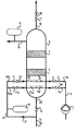
- primary coolant water to be injected with gas, flows into a pressurised water reactor system (not shown) via a line 14 in the direction of an arrow 19 and, after the adjustment of the volume flow at a control valve 10, flows into a bubble column 6 at a liquid inlet 20.
- a gas metering, proportioning or dosage equipment e.g. a gas dosage or proportioning pump 1
- hydrogen gas in a conduit 2 is channelled into the bubble column 6 and is injected above the liquid inlet 20 via either one of two gas injection conduits 2a and 2b and either of two sets of jet nozzles 5 and 5a.
- the conduits 2a, 2b are fitted with respective isolation valves 3a, 3.
- the nozzles 5 are supported and connected together and to the conduit 2b by a gas injection conduit 22 within the bubble column 6.
- the nozzles 5a are supported and connected together and to the conduit 2a by a gas injection conduit 22a within the bubble column 6.
- the conduits 22, 22a are parallel.
- a bypass conduit 13 in which a certain portion of the primary coolant that is to be injected with gas flows in the direction of an arrow 21, branches off from the conduit 14 and is divided into twin coolant injection conduits 13a, 13b fitted with respective isolation valves 11, 11 a.
- the conduits 13a, 13b are connected to the conduits 22, 22a, respectively.
- the mode of operation of the apparatus enables the nozzles 5, 5a to be alternately flushed or used for gas injection.
- the isolation valves 3 and 11 a are closed and the isolation valves 11 and 3a are opened, whereby coolant flows through the nozzles 5 to flush them and gas is injected through the nozzles 5a.
- the isolation valves 3a and 11 are closed and the isolation valves 11 a and 3 are opened, whereby coolant flows through the nozzles 5a to flush them and gas is injected through the nozzles 5.
- Check valves 4 and 12 prevent gas or flushing liquid from returning to their respective sources.
- An analysis measuring device 8 is installed in the bypass conduit to measure the hydrogen gas concentration of the liquid to be injected with gas so that exact gas dosing can be accomplished through the gas dosage pump 1 as a function of gas content and liquid volume in the conduit 14.
- a further analysis measuring device 9 is installed in the conduit 15 to measure the hydrogen gas concentration of the gassed liquid leaving the bubble column 6.
- Nitrogen moreover, can be used as a gas blanket for the makeup tank, in order to avoid the danger of a combustible gas explosion.
- An additional advantage of the above-described embodiment of the invention is the fact that the hydrogen concentration of the primary coolant reinjected into the reactor can be kept within a specified range during load change processes.
Landscapes
- Physics & Mathematics (AREA)
- Engineering & Computer Science (AREA)
- Chemical Kinetics & Catalysis (AREA)
- General Engineering & Computer Science (AREA)
- High Energy & Nuclear Physics (AREA)
- Chemical & Material Sciences (AREA)
- Plasma & Fusion (AREA)
- Monitoring And Testing Of Nuclear Reactors (AREA)
- Accessories For Mixers (AREA)
- Preventing Corrosion Or Incrustation Of Metals (AREA)
- Geophysics And Detection Of Objects (AREA)
- Organic Low-Molecular-Weight Compounds And Preparation Thereof (AREA)
- Measuring Volume Flow (AREA)
Description
- This invention relates to a method of and apparatus for introducing gas into the reactor coolant liquid of pressurised water nuclear power plants.
- It is not uncommon in nuclear plants to introduce hydrogen gas into primary coolant water by spraying the primary coolant into a hydrogen atmosphere, e.g. into a hydrogen gas blanket of a makeup tank, or by bubbling hydrogen gas into a water phase of the makeup tank. The makeup tank, among other things, is used to equalise primary coolant volume changes, and contains both the primary coolant and the hydrogen-gas blanket.
- These known methods have the disadvantage that due to the large hydrogen volume in the makeup tank, a release of relatively large hydrogen volumes into the space surrounding the makeup tank is possible, and therefore the occurrence of combustible gas explosions must be taken into account. Further, the gas/water concentration cannot be precisely controlled.
- French Patent Application Publication No. 2 285 172 discloses the introduction of hydrogen gas into water destined to be used as reactor coolant liquid for a nuclear reactor. The water passes through a tubular container or cell that has a water inlet and the gas is introduced in a controlled manner via a conduit into the liquid within the container. The French Patent Publication teaches that the direct injection of gas into the reactor coolant liquid circuit or into a tank containing the liquid is subject to certain disadvantages and resorts to the alternative approach of diffusing the gas into the water within the container.
- There is still a need, therefore, to find a method of injecting gas into the reactor coolant liquid for pressurised water nuclear power plants, by which a predetermined gas concentration can be reached in the liquid and by which the potential release of dangerous volumes of explosive gas can be minimised.
- According to the invention the above need is satisfied by a method of introducing gas into the reactor coolant liquid for pressurised water nuclear power plants, wherein the liquid is passed through a container that has a liquid inlet and the gas is introduced into the liquid within the container in a manner to provide a predetermined gas concentration in the liquid, characterised in that the reactor coolant liquid is passed through a container in the form of a bubble column, the gas is injected into the reactor coolant liquid passing through the bubble column above the liquid inlet, and the gas and liquid are mixed prior to leaving the bubble column.
- The invention also provides apparatus for introducing gas into the reactor coolant liquid for pressurised water nuclear power plants, the apparatus comprising a container, means to cause the liquid to pass through the container, a gas conduit within the container to direct gas into the container, and means to control the flow of gas into the container, characterised in that the container is a bubble column, jet nozzles are provided within the column to inject the gas into the reactor coolant liquid passing through the bubble column, and a plurality of static mixers are provided within the column to mix the gas and liquid.
- In accordance with a preferred embodiment of the invention described in more detail below, the nozzles can be flushed with the aid of a bypass flow of the liquid to be gassed. To this end, a by-pass liquid flow conduit is divided into two conduits that are connected to a pair of the gas injection conduits within the bubble column, which are in the form of pipe sections that support the nozzles. Isolation valves in the two bypass flow conduits can be manipulated to enable the nozzles to be alternately supplied with gas and flushing liquid. Flushing of the nozzles is desirable in that the reactor coolant liquid is a salt solution, whereby there is a danger of closure of one or more of the nozzles due to precipitation arising from local solubility excess.
- In the preferred embodiment, a ventilation conduit is connected to the bubble column in order to prevent gas bubble formation in the liquid. Analysis measuring devices are installed in the liquid line upstream and downstream of the bubble column to measure the gas concentration. The gas volume injected depends upon the pre-existing gas concentration of the liquid to be injected with gas, and the head of the liquid flow.
- The invention will now be further described, by way of example, with reference to the accompanying schematic drawings, the sole figure of which depicts a method and apparatus embodying the invention.
- Referring to the drawing, primary coolant water, to be injected with gas, flows into a pressurised water reactor system (not shown) via a
line 14 in the direction of an arrow 19 and, after the adjustment of the volume flow at acontrol valve 10, flows into abubble column 6 at aliquid inlet 20. With the aid of a gas metering, proportioning or dosage equipment, e.g. a gas dosage or proportioning pump 1, hydrogen gas in a conduit 2 is channelled into thebubble column 6 and is injected above theliquid inlet 20 via either one of twogas injection conduits conduits respective isolation valves conduit 2b by agas injection conduit 22 within thebubble column 6. The nozzles 5a are supported and connected together and to theconduit 2a by a gas injection conduit 22a within thebubble column 6. Theconduits 22, 22a are parallel. - Hydrogen gas and primary coolant are now intensively mixed when liquid flows through
static mixers 7 enclosed by thebubble column 6. After the liquid has flowed through themixers 7, the primary coolant, which has been provided with the desired hydrogen content, discharges from thebubble column 6 through aconduit 15. Automatic ventilation through a conduit 16, a float valve 17 and an isolation valve 18 ensures that no gas bubbles remain in the primary coolant. A bypass conduit 13, in which a certain portion of the primary coolant that is to be injected with gas flows in the direction of anarrow 21, branches off from theconduit 14 and is divided into twincoolant injection conduits respective isolation valves conduits conduits 22, 22a, respectively. - The mode of operation of the apparatus enables the nozzles 5, 5a to be alternately flushed or used for gas injection. To flush the nozzles 5, the
isolation valves isolation valves isolation valves isolation valves valves 4 and 12 prevent gas or flushing liquid from returning to their respective sources. - An analysis measuring device 8 is installed in the bypass conduit to measure the hydrogen gas concentration of the liquid to be injected with gas so that exact gas dosing can be accomplished through the gas dosage pump 1 as a function of gas content and liquid volume in the
conduit 14. A further analysis measuringdevice 9 is installed in theconduit 15 to measure the hydrogen gas concentration of the gassed liquid leaving thebubble column 6. - It should be noted that the entire gassing and flushing process takes place automatically.
- The above-described embodiment of the invention enables liquids to be injected with gas in a simplified and advantageous manner. Nitrogen, moreover, can be used as a gas blanket for the makeup tank, in order to avoid the danger of a combustible gas explosion.
- An additional advantage of the above-described embodiment of the invention is the fact that the hydrogen concentration of the primary coolant reinjected into the reactor can be kept within a specified range during load change processes.
Claims (6)
Applications Claiming Priority (2)
| Application Number | Priority Date | Filing Date | Title |
|---|---|---|---|
| DE2748159 | 1977-10-27 | ||
| DE2748159A DE2748159C2 (en) | 1977-10-27 | 1977-10-27 | Device for gassing the primary coolant of a water-cooled nuclear reactor plant |
Publications (2)
| Publication Number | Publication Date |
|---|---|
| EP0001903A1 EP0001903A1 (en) | 1979-05-16 |
| EP0001903B1 true EP0001903B1 (en) | 1981-10-21 |
Family
ID=6022389
Family Applications (1)
| Application Number | Title | Priority Date | Filing Date |
|---|---|---|---|
| EP78300549A Expired EP0001903B1 (en) | 1977-10-27 | 1978-10-26 | Method of and apparatus for introducing gas into the coolant liquid of nuclear reactors |
Country Status (11)
| Country | Link |
|---|---|
| US (1) | US4487740A (en) |
| EP (1) | EP0001903B1 (en) |
| JP (1) | JPS5923398B2 (en) |
| AT (1) | AT364045B (en) |
| CA (1) | CA1131887A (en) |
| CH (1) | CH635521A5 (en) |
| DE (1) | DE2748159C2 (en) |
| ES (1) | ES474579A1 (en) |
| IL (1) | IL55769A (en) |
| IT (1) | IT1104225B (en) |
| SE (1) | SE429696B (en) |
Families Citing this family (5)
| Publication number | Priority date | Publication date | Assignee | Title |
|---|---|---|---|---|
| DE2828153C3 (en) * | 1978-06-27 | 1984-07-26 | Kraftwerk Union AG, 4330 Mülheim | Nuclear reactor with a liquid coolant |
| DE2948297C2 (en) * | 1978-06-27 | 1985-01-17 | Kraftwerk Union AG, 4330 Mülheim | Nuclear reactor with a liquid coolant |
| US4749505A (en) * | 1985-07-08 | 1988-06-07 | Exxon Chemical Patents Inc. | Olefin polymer viscosity index improver additive useful in oil compositions |
| RU2254626C2 (en) * | 2003-08-21 | 2005-06-20 | Государственное унитарное предприятие Опытное конструкторское бюро машиностроения им. Африкантова И.И. | Steam pressurizer |
| CN109342492B (en) * | 2018-11-23 | 2021-09-10 | 哈尔滨工程大学 | Experimental device and experimental method for researching bubble rupture behavior characteristics of aerosol-containing liquid pool surface |
Family Cites Families (24)
| Publication number | Priority date | Publication date | Assignee | Title |
|---|---|---|---|---|
| US3124518A (en) * | 1964-03-10 | Product | ||
| US3113913A (en) * | 1963-12-10 | Sealing and purging system for pressurized water reactor | ||
| US955004A (en) * | 1909-07-31 | 1910-04-12 | William O Singer | Wrench. |
| GB694918A (en) * | 1951-02-23 | 1953-07-29 | F S Gibbs Inc | Diffusion of gases in liquids |
| US2937981A (en) * | 1951-06-22 | 1960-05-24 | Augustine O Allen | Suppression of water decomposition |
| BE564488A (en) * | 1957-02-07 | |||
| US3353797A (en) * | 1964-07-08 | 1967-11-21 | Sonic Eng Corp | Mixing system |
| GB1029648A (en) * | 1964-05-22 | 1966-05-18 | Ca Atomic Energy Ltd | Method of suppressing radiolytic water decomposition in nuclear reactors |
| BE754657Q (en) * | 1965-11-29 | 1971-01-18 | Kenics Corp | MIXER APPLIANCE |
| DE1277488B (en) * | 1967-06-08 | 1968-09-12 | Siemens Ag | Device for the electromagnetic removal of iron oxides from liquid |
| US3575294A (en) * | 1967-11-27 | 1971-04-20 | Nippon Rensui Kk | Counterflow, moving bed type, ion exchange apparatus |
| US3450388A (en) * | 1968-03-12 | 1969-06-17 | Gen Motors Corp | Mixer with flushing valve in the outlet |
| US3663725A (en) * | 1970-04-23 | 1972-05-16 | Gen Electric | Corrosion inhibition |
| CA935571A (en) * | 1970-05-19 | 1973-10-16 | Westinghouse Electric Corporation | Boron control system for a nuclear power plant |
| US4039289A (en) * | 1971-02-08 | 1977-08-02 | Chemsoil Corporation | Sulphur-burning and gaseous products absorption system and components therefor |
| DE2133250C3 (en) * | 1971-07-05 | 1980-11-20 | Kraftwerk Union Ag, 4330 Muehlheim | Device for the adsorptive delay of radioactive gases in an exhaust gas flow |
| CH543799A (en) * | 1971-12-22 | 1973-10-31 | Kraftwerk Union Ag | Nuclear power plant with pressurized water reactor |
| DE2302905C2 (en) * | 1973-01-22 | 1982-10-28 | Siemens AG, 1000 Berlin und 8000 München | Process for the preparation of gas mixtures from pressurized water reactors |
| US3944466A (en) * | 1973-07-16 | 1976-03-16 | Westinghouse Electric Corporation | Reducing concentration of gases in nuclear reactor |
| US3976541A (en) * | 1974-03-18 | 1976-08-24 | Combustion Engineering, Inc. | Secondary coolant purification system with demineralizer bypass |
| JPS5141082U (en) * | 1974-09-20 | 1976-03-26 | ||
| FR2285172A1 (en) * | 1974-09-20 | 1976-04-16 | Commissariat Energie Atomique | Diffusion of hydrogen into pressurised water - using palladium based selectively permeable barrier |
| CH607934A5 (en) * | 1976-01-27 | 1978-12-15 | Sulzer Ag | Appliance for introducing gases into liquids and/or liquid-solid mixtures |
| UST955004I4 (en) | 1976-04-05 | 1977-02-01 | Westinghouse Electric Corporation | Method for heat exchanger leak detection in a liquid metal cooled nuclear reactor |
-
1977
- 1977-10-27 DE DE2748159A patent/DE2748159C2/en not_active Expired
-
1978
- 1978-10-02 US US05/947,671 patent/US4487740A/en not_active Expired - Lifetime
- 1978-10-03 CH CH1024778A patent/CH635521A5/en not_active IP Right Cessation
- 1978-10-05 CA CA312,773A patent/CA1131887A/en not_active Expired
- 1978-10-18 AT AT0748878A patent/AT364045B/en not_active IP Right Cessation
- 1978-10-19 IL IL55769A patent/IL55769A/en unknown
- 1978-10-23 JP JP53129542A patent/JPS5923398B2/en not_active Expired
- 1978-10-24 SE SE7811046A patent/SE429696B/en not_active IP Right Cessation
- 1978-10-26 ES ES474579A patent/ES474579A1/en not_active Expired
- 1978-10-26 IT IT09627/78A patent/IT1104225B/en active
- 1978-10-26 EP EP78300549A patent/EP0001903B1/en not_active Expired
Also Published As
| Publication number | Publication date |
|---|---|
| EP0001903A1 (en) | 1979-05-16 |
| IL55769A (en) | 1981-07-31 |
| SE7811046L (en) | 1979-04-28 |
| ES474579A1 (en) | 1979-06-01 |
| DE2748159C2 (en) | 1984-06-20 |
| DE2748159A1 (en) | 1979-05-03 |
| CH635521A5 (en) | 1983-04-15 |
| AT364045B (en) | 1981-09-25 |
| ATA748878A (en) | 1981-02-15 |
| US4487740A (en) | 1984-12-11 |
| IT7809627A0 (en) | 1978-10-26 |
| CA1131887A (en) | 1982-09-21 |
| IT1104225B (en) | 1985-10-21 |
| SE429696B (en) | 1983-09-19 |
| JPS5923398B2 (en) | 1984-06-01 |
| JPS55453A (en) | 1980-01-05 |
Similar Documents
| Publication | Publication Date | Title |
|---|---|---|
| US5273664A (en) | Apparatus and method for disinfection of water by ozone injection | |
| KR102106423B1 (en) | Mobile boration system | |
| JPH05508715A (en) | Reactivity control device and method | |
| EP0001903A1 (en) | Method of and apparatus for introducing gas into the coolant liquid of nuclear reactors | |
| US4282062A (en) | Procedure and equipment for injecting gas into liquids | |
| KR102519992B1 (en) | Mobile boric acid injection system | |
| US4374083A (en) | Nuclear reactor having a liquid coolant | |
| KR820001225B1 (en) | Method for introducing gas into the coolant liquid of nuclear reactors | |
| KR19990063905A (en) | Apparatus for providing gas to the primary coolant of the pressurized water reactor | |
| US3227619A (en) | Apparatus for controlling a nuclear reactor by absorbent gas and device for its application | |
| US7624970B2 (en) | Method for the absorption of a gas in a liquid and an apparatus for this | |
| EP0791391A1 (en) | Multi-phase mixing in a hydraulic jump | |
| JPH10315261A5 (en) | ||
| US9281087B2 (en) | Mobile boration system | |
| Markofsky | On the reoxygenation efficiency of diffused air aeration | |
| SU453983A1 (en) | Method of liquid control of nuclear reactor reactivity | |
| JPS6319238B2 (en) | ||
| KR820001249B1 (en) | Procedure and equipment for injecting gas into liquids | |
| SU691733A1 (en) | Apparatus for studying kinetics of gas release | |
| Charlton et al. | Discussion of “Purging of Saline Wedges from Ocean Outfalls” by David L. Wilkinson (December, 1984, Vol. 110, No. 12) | |
| GB1267578A (en) | Foam-producing apparatus for fire-fighting | |
| RU2043942C1 (en) | Method and device for mixing oxygen with hydrogen-containing mixtures | |
| JPS5742330A (en) | Liquid distributor | |
| JPS5672711A (en) | Continuous mixer for mixed fluid | |
| ITVR20090061A1 (en) | PROCEDURE AND PLANT FOR THE TREATMENT OF TWO FLUIDS |
Legal Events
| Date | Code | Title | Description |
|---|---|---|---|
| PUAI | Public reference made under article 153(3) epc to a published international application that has entered the european phase |
Free format text: ORIGINAL CODE: 0009012 |
|
| AK | Designated contracting states |
Designated state(s): BE FR GB LU NL |
|
| 17P | Request for examination filed | ||
| GRAA | (expected) grant |
Free format text: ORIGINAL CODE: 0009210 |
|
| AK | Designated contracting states |
Designated state(s): BE FR GB LU NL |
|
| PG25 | Lapsed in a contracting state [announced via postgrant information from national office to epo] |
Ref country code: LU Free format text: LAPSE BECAUSE OF NON-PAYMENT OF DUE FEES Effective date: 19811031 |
|
| RAP2 | Party data changed (patent owner data changed or rights of a patent transferred) |
Owner name: BROWN BOVERI REAKTOR GMBH |
|
| REG | Reference to a national code |
Ref country code: FR Ref legal event code: ST |
|
| REG | Reference to a national code |
Ref country code: FR Ref legal event code: AR |
|
| REG | Reference to a national code |
Ref country code: FR Ref legal event code: BR |
|
| PGFP | Annual fee paid to national office [announced via postgrant information from national office to epo] |
Ref country code: LU Payment date: 19831006 Year of fee payment: 6 |
|
| PGFP | Annual fee paid to national office [announced via postgrant information from national office to epo] |
Ref country code: FR Payment date: 19841016 Year of fee payment: 7 |
|
| PGFP | Annual fee paid to national office [announced via postgrant information from national office to epo] |
Ref country code: NL Payment date: 19871031 Year of fee payment: 10 |
|
| PGFP | Annual fee paid to national office [announced via postgrant information from national office to epo] |
Ref country code: BE Payment date: 19890126 Year of fee payment: 11 |
|
| PG25 | Lapsed in a contracting state [announced via postgrant information from national office to epo] |
Ref country code: NL Effective date: 19890501 |
|
| NLV4 | Nl: lapsed or anulled due to non-payment of the annual fee | ||
| PG25 | Lapsed in a contracting state [announced via postgrant information from national office to epo] |
Ref country code: GB Effective date: 19891026 |
|
| PG25 | Lapsed in a contracting state [announced via postgrant information from national office to epo] |
Ref country code: BE Effective date: 19891031 |
|
| BERE | Be: lapsed |
Owner name: BROWN BOVERI REAKTOR G.M.B.H. Effective date: 19891031 |
|
| GBPC | Gb: european patent ceased through non-payment of renewal fee | ||
| PG25 | Lapsed in a contracting state [announced via postgrant information from national office to epo] |
Ref country code: FR Effective date: 19900629 |
|
| REG | Reference to a national code |
Ref country code: FR Ref legal event code: ST |
|
| PLBE | No opposition filed within time limit |
Free format text: ORIGINAL CODE: 0009261 |
|
| STAA | Information on the status of an ep patent application or granted ep patent |
Free format text: STATUS: NO OPPOSITION FILED WITHIN TIME LIMIT |