EP0001528B1 - Dispositif de support d'une descente de vent de haut-fourneau - Google Patents
Dispositif de support d'une descente de vent de haut-fourneau Download PDFInfo
- Publication number
- EP0001528B1 EP0001528B1 EP78400119A EP78400119A EP0001528B1 EP 0001528 B1 EP0001528 B1 EP 0001528B1 EP 78400119 A EP78400119 A EP 78400119A EP 78400119 A EP78400119 A EP 78400119A EP 0001528 B1 EP0001528 B1 EP 0001528B1
- Authority
- EP
- European Patent Office
- Prior art keywords
- blast
- support unit
- support
- downpipe
- fixed
- Prior art date
- Legal status (The legal status is an assumption and is not a legal conclusion. Google has not performed a legal analysis and makes no representation as to the accuracy of the status listed.)
- Expired
Links
- 230000000295 complement effect Effects 0.000 claims description 2
- 238000009434 installation Methods 0.000 description 8
- 241001481833 Coryphaena hippurus Species 0.000 description 2
- 230000000694 effects Effects 0.000 description 2
- 230000000903 blocking effect Effects 0.000 description 1
- 238000001816 cooling Methods 0.000 description 1
Images

Classifications
-
- C—CHEMISTRY; METALLURGY
- C21—METALLURGY OF IRON
- C21B—MANUFACTURE OF IRON OR STEEL
- C21B7/00—Blast furnaces
- C21B7/16—Tuyéres
- C21B7/163—Blowpipe assembly
-
- F—MECHANICAL ENGINEERING; LIGHTING; HEATING; WEAPONS; BLASTING
- F16—ENGINEERING ELEMENTS AND UNITS; GENERAL MEASURES FOR PRODUCING AND MAINTAINING EFFECTIVE FUNCTIONING OF MACHINES OR INSTALLATIONS; THERMAL INSULATION IN GENERAL
- F16L—PIPES; JOINTS OR FITTINGS FOR PIPES; SUPPORTS FOR PIPES, CABLES OR PROTECTIVE TUBING; MEANS FOR THERMAL INSULATION IN GENERAL
- F16L3/00—Supports for pipes, cables or protective tubing, e.g. hangers, holders, clamps, cleats, clips, brackets
- F16L3/08—Supports for pipes, cables or protective tubing, e.g. hangers, holders, clamps, cleats, clips, brackets substantially surrounding the pipe, cable or protective tubing
Definitions
- the present invention relates to installations for supplying hot air or hot wind to blast furnaces.
- Such installations usually include blowers supplying hot air to a circular pipe surrounding the blast furnace and connected to the nozzles by a number of pipes called downspouts.
- These wind descents are made in several sections fixed to each other by suitable means and some of these elements are suspended from the shielding of the blast furnace by tie rods or tensioners.
- tie rods or tensioners usually include blowers supplying hot air to a circular pipe surrounding the blast furnace and connected to the nozzles by a number of pipes called downspouts.
- the object of this invention is to provide a device for supporting or suspending an element or section of a wind-down pipe with respect to the shielding of a blast furnace, which does not have these disadvantages, and which allows to ensure in good conditions and with great precision the assembly and disassembly of the elements or sections located downstream of this element.
- a support assembly rigidly fixed to the shield of the blast furnace and delimiting at least one roughly horizontal support and guide slide for a complementary member carried by an element of the downspout, means being also provided for horizontally blocking said element of the wind descent relative to the support assembly during a stop of the installation and the dismantling of another element of this wind descent.
- the support assembly comprises two pairs of parallel slides between which is guided said member carried by the wind descent element, and this support is preferably made in two parts, one fixed to the shielding, the other fixed to the first and delimiting the slides, the part fixed to the shielding having, according to another characteristic, an adjustable stop intended to absorb the vertical forces generated during the operation of the installation.
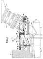
- Fig. 1 part of an installation for supplying hot air or hot wind to a blast furnace, the shielding of which is designated by the reference 1.
- the installation comprises a circular 2 and a downspout 3 made of several elements, or sections and in particular a lower conical element 4 on which is fixed an intermediate part 5 in the shape of a T or dolphin, itself carrying a nozzle 6 intended to be connected to a nozzle.
- a support device 10 produced here in two main parts 11, 12, provides the support and the guiding of the lower conical element 4 of the wind descent.
- the support device comprises a support itself 11 fixed to the shield of the blast furnace, for example by bolts 13.
- This support mainly comprises a rear wall 14, reinforced by at least one fitting 15 bearing on a horizontal surface 7 of the shielding, two lateral wings 16, an upper wall 17 cut to allow the passage of conduits or pipes such as 18, and a front wall 19.
- the sub-assembly 12 having in plan a U-shaped (Fig. 3) and having vertical walls 21, 22, 23, one of which 21 allows attachment to the front face 19 of the support and the other two side 22, 23 of which support upper elements of slide 24, 25.
- the lower elements of these slides consist of the upper horizontal surfaces 26, 27 of a lower wall 28 of the subassembly 12, welded to the vertical walls 21, 22, 23.
- This horizontal wall or plate has a U shape for pe put the passage of the cone 4.
- the upper elements 24, 25 of the slides have an L-shaped section and are fixed by means of bolts 29 on the vertical wings of the sub-assembly 12.
- the device is completed by a cross-member 30 which is guided by its two U-shaped ends, 31, on the two wings of the plate 28 and fixed to this plate by two pins 32 or other suitable means.
- the crosspiece 30 carries at its lower part a simple mechanism for locking the lower cone in position.
- This mechanism comprises a nut 33 fixed in translation but mounted free to rotate, and a screw 34 which can move in translation, and terminated by a yoke 35 whose two opposite branches are pierced with coaxial orifices 36.
- This yoke can come into engagement sure a fitting 37 carried by the lower cone 4 and provided with an orifice (not visible in the drawing).
- the yoke 35 and the fitting 37 can be made integral by means of a pin 38 which is engaged in the orifices 36.
- At least one adjustable stop 39 constituted by a knurled cap, screwed onto a threaded rod 40, is provided at the rear part of the support 11. This stop is intended to carry over; shielding of vertical forces, directed upwards, generated in operation under the effect of temperature variations.
- On the cone 4 is welded or fixed by any other means a plate 41, arranged so as to be received between the slide elements 24, 26 and 25, 27, respectively.
- the joint plane between the lower cone 4 and the dolphin 5 is perfectly determined due to the mounting of the cone in the slides, contrary to what occurs when this same cone is supported by tie rods which cannot prevent a tilting movement of this part, especially during its cooling.
- This joint plane being perfectly defined, the nozzle adapts precisely and without any particular adjustment in the heel of the nozzle.
- the yoke 35 is released from the fitting 37 so as to allow deflections of the downward wind, during expansions and deformations occurring under the effect of the rise in temperature.
- the adjustable stop means 39, 40 provided according to a characteristic of the invention are important because they make it possible to achieve precise and effective support of the upper part of the support against the shielding, making it possible to withstand the forces without damage. vertical which can be generated in use by the significant temperature rises to which the downwind and its support are subjected.
Landscapes
- Engineering & Computer Science (AREA)
- General Engineering & Computer Science (AREA)
- Chemical & Material Sciences (AREA)
- Materials Engineering (AREA)
- Metallurgy (AREA)
- Organic Chemistry (AREA)
- Manufacturing & Machinery (AREA)
- Mechanical Engineering (AREA)
- Blast Furnaces (AREA)
- Supports For Pipes And Cables (AREA)
- Aerodynamic Tests, Hydrodynamic Tests, Wind Tunnels, And Water Tanks (AREA)
- Working Measures On Existing Buildindgs (AREA)
- Drying Of Solid Materials (AREA)
Applications Claiming Priority (2)
| Application Number | Priority Date | Filing Date | Title |
|---|---|---|---|
| FR7729508A FR2404674A1 (fr) | 1977-09-30 | 1977-09-30 | Dispositif de support d'une descente de vent de haut-fourneau |
| FR7729508 | 1977-09-30 |
Publications (2)
| Publication Number | Publication Date |
|---|---|
| EP0001528A1 EP0001528A1 (fr) | 1979-04-18 |
| EP0001528B1 true EP0001528B1 (fr) | 1980-09-03 |
Family
ID=9195981
Family Applications (1)
| Application Number | Title | Priority Date | Filing Date |
|---|---|---|---|
| EP78400119A Expired EP0001528B1 (fr) | 1977-09-30 | 1978-09-29 | Dispositif de support d'une descente de vent de haut-fourneau |
Country Status (10)
| Country | Link |
|---|---|
| US (1) | US4212253A (enExample) |
| EP (1) | EP0001528B1 (enExample) |
| JP (1) | JPS5457410A (enExample) |
| BE (1) | BE870743A (enExample) |
| DE (1) | DE2860147D1 (enExample) |
| ES (1) | ES473813A1 (enExample) |
| FR (1) | FR2404674A1 (enExample) |
| GB (1) | GB2005813B (enExample) |
| IT (2) | IT1108467B (enExample) |
| LU (1) | LU80295A1 (enExample) |
Families Citing this family (5)
| Publication number | Priority date | Publication date | Assignee | Title |
|---|---|---|---|---|
| US4685703A (en) * | 1986-05-27 | 1987-08-11 | Phillips Petroleum Company | Expansible and contractible duct |
| GB8704407D0 (en) * | 1987-02-25 | 1987-04-01 | Davy Mckee Stockton | Tuyere stock |
| US4818216A (en) * | 1988-06-20 | 1989-04-04 | Yates Phillip J | Method and apparatus for removing fuel gun from boiler |
| AU608987B2 (en) * | 1988-07-19 | 1991-04-18 | Paul Wurth S.A. | Device for injecting preheated air in a shaft furnace |
| LU87730A1 (fr) * | 1990-04-27 | 1991-11-15 | Wurth Paul Sa | Dispositif d'injection d'air prechauffe dans un four a cuve |
Family Cites Families (6)
| Publication number | Priority date | Publication date | Assignee | Title |
|---|---|---|---|---|
| US299536A (en) * | 1884-06-03 | Tuyere and attachment therefor | ||
| US1847835A (en) * | 1930-06-09 | 1932-03-01 | Harvey B Jordan | Tuyere stock bridle |
| US2135252A (en) * | 1935-11-06 | 1938-11-01 | Grover Ray | Furnace blower mounting |
| DE1937139A1 (de) * | 1969-07-22 | 1971-02-04 | Neuhoff Helmut | Vorrichtung zum Manipulieren von insbesondere Duesenkruemmern |
| LU64911A1 (enExample) * | 1972-03-06 | 1972-07-06 | ||
| SE390755B (sv) * | 1974-10-07 | 1977-01-17 | Goetaverken Angteknik Ab | Anordning for att reglera lufttillforseln vid en eldstad |
-
1977
- 1977-09-30 FR FR7729508A patent/FR2404674A1/fr active Granted
-
1978
- 1978-09-21 GB GB7837607A patent/GB2005813B/en not_active Expired
- 1978-09-25 BE BE190691A patent/BE870743A/xx not_active IP Right Cessation
- 1978-09-28 LU LU80295A patent/LU80295A1/xx unknown
- 1978-09-29 EP EP78400119A patent/EP0001528B1/fr not_active Expired
- 1978-09-29 IT IT69245/78A patent/IT1108467B/it active
- 1978-09-29 JP JP12030778A patent/JPS5457410A/ja active Granted
- 1978-09-29 IT IT7853750U patent/IT7853750V0/it unknown
- 1978-09-29 ES ES473813A patent/ES473813A1/es not_active Expired
- 1978-09-29 US US05/946,736 patent/US4212253A/en not_active Expired - Lifetime
- 1978-09-29 DE DE7878400119T patent/DE2860147D1/de not_active Expired
Also Published As
| Publication number | Publication date |
|---|---|
| JPS62963B2 (enExample) | 1987-01-10 |
| IT7853750V0 (it) | 1978-09-29 |
| JPS5457410A (en) | 1979-05-09 |
| IT1108467B (it) | 1985-12-09 |
| US4212253A (en) | 1980-07-15 |
| EP0001528A1 (fr) | 1979-04-18 |
| DE2860147D1 (en) | 1980-12-11 |
| FR2404674B1 (enExample) | 1980-04-11 |
| GB2005813B (en) | 1982-02-03 |
| BE870743A (fr) | 1979-03-26 |
| ES473813A1 (es) | 1979-04-16 |
| LU80295A1 (fr) | 1979-03-16 |
| FR2404674A1 (fr) | 1979-04-27 |
| GB2005813A (en) | 1979-04-25 |
| IT7869245A0 (it) | 1978-09-29 |
Similar Documents
| Publication | Publication Date | Title |
|---|---|---|
| EP0001528B1 (fr) | Dispositif de support d'une descente de vent de haut-fourneau | |
| EP0445599B1 (fr) | Sonde de prise d'échantillons gazeux et de mesures thermiques dans un four à cuve | |
| EP0250344B1 (fr) | Installation pour la réparation et le contrôle de carrosseries de véhicules accidentés | |
| EP3092469B1 (en) | Optical pyrometer | |
| CH637862A5 (fr) | Machine a decouper un materiau en feuille. | |
| CN105710573A (zh) | 一种角度可调的焊接平台 | |
| EP0616336B1 (fr) | Procédé et dispositif de remplacement d'un adaptateur de traversée du couvercle de la cuve d'un réacteur nucléaire | |
| EP0094883A1 (fr) | Dispositif de cisaillage d'assemblages combustibles irradiés | |
| EP0081431B1 (fr) | Dispositif de fixation d'un assemblage combustible sur la plaque inférieure de support du coeur, dans un réacteur nucléaire | |
| EP0349379B1 (fr) | Grappe de réglage à crayons démontables pour assemblage combustible nucléaire | |
| CN112296421A (zh) | 一种金属管道的自动化切割设备 | |
| EP1703041B1 (fr) | Corps d'échange thermique adapté à une tour de refroidissement tour de refroidissement et procédé d'assemblage associés | |
| EP2871413A2 (en) | Burner retraction system | |
| BE1007333A3 (fr) | Dispositif et procede de redressage des ailettes de guidage des grilles-entretoises d'un assemblage combustible d'un reacteur nucleaire. | |
| BE1007332A3 (fr) | Dispositif et procede d'extraction de crayons peripheriques d'un assemblage combustible d'un reacteur nucleaire. | |
| FR2651960A1 (fr) | Dispositif pour le taillage de haies. | |
| EP0912274B1 (fr) | Dispositif de positionnement d'un bloc-filiere d'une table de coulee d'une machine de coulee continue verticale ascendante | |
| CN223570666U (zh) | 一种猪饲料生产反应釜加工用上料装置 | |
| WO2005062312A2 (fr) | Systeme d'etancheite d'une colonne d'instrumentation traversant un couvercle d'une enceinte sous pression et procede de montage et de demontage d'un tel systeme d'etancheite | |
| CN111101844A (zh) | 一种用于机电设备安装的工程梯 | |
| CN214651274U (zh) | 一种易于拆卸的支撑结构 | |
| FR3160421A1 (fr) | Pige de nivellement pour le coulage d’une chape de béton | |
| FR2654460A1 (fr) | Procede et appareillage pour l'amenagement d'une echelle a l'interieur des chambres de tirage et fosses betonnees similaires. | |
| FR2494410A1 (fr) | Dispositif de protection thermique destine a proteger un operateur travaillant dans un conduit | |
| WO1994025631A1 (fr) | Trou de coulee pour un four a cuve, notamment un haut-fourneau |
Legal Events
| Date | Code | Title | Description |
|---|---|---|---|
| PUAI | Public reference made under article 153(3) epc to a published international application that has entered the european phase |
Free format text: ORIGINAL CODE: 0009012 |
|
| AK | Designated contracting states |
Designated state(s): DE NL |
|
| 17P | Request for examination filed | ||
| GRAA | (expected) grant |
Free format text: ORIGINAL CODE: 0009210 |
|
| AK | Designated contracting states |
Designated state(s): DE NL |
|
| REF | Corresponds to: |
Ref document number: 2860147 Country of ref document: DE Date of ref document: 19801211 |
|
| PGFP | Annual fee paid to national office [announced via postgrant information from national office to epo] |
Ref country code: DE Payment date: 19930818 Year of fee payment: 16 |
|
| PGFP | Annual fee paid to national office [announced via postgrant information from national office to epo] |
Ref country code: NL Payment date: 19930930 Year of fee payment: 16 |
|
| PG25 | Lapsed in a contracting state [announced via postgrant information from national office to epo] |
Ref country code: NL Effective date: 19950401 |
|
| NLV4 | Nl: lapsed or anulled due to non-payment of the annual fee | ||
| PG25 | Lapsed in a contracting state [announced via postgrant information from national office to epo] |
Ref country code: DE Effective date: 19950601 |
|
| PLBE | No opposition filed within time limit |
Free format text: ORIGINAL CODE: 0009261 |
|
| STAA | Information on the status of an ep patent application or granted ep patent |
Free format text: STATUS: NO OPPOSITION FILED WITHIN TIME LIMIT |