EP0001527B1 - Dispositif d'assemblage, notamment entre deux tronçons d'une descente de vent de haut-fourneau - Google Patents
Dispositif d'assemblage, notamment entre deux tronçons d'une descente de vent de haut-fourneau Download PDFInfo
- Publication number
- EP0001527B1 EP0001527B1 EP78400115A EP78400115A EP0001527B1 EP 0001527 B1 EP0001527 B1 EP 0001527B1 EP 78400115 A EP78400115 A EP 78400115A EP 78400115 A EP78400115 A EP 78400115A EP 0001527 B1 EP0001527 B1 EP 0001527B1
- Authority
- EP
- European Patent Office
- Prior art keywords
- support
- collar
- elements
- flanges
- apertures
- Prior art date
- Legal status (The legal status is an assumption and is not a legal conclusion. Google has not performed a legal analysis and makes no representation as to the accuracy of the status listed.)
- Expired
Links
Images

Classifications
-
- F—MECHANICAL ENGINEERING; LIGHTING; HEATING; WEAPONS; BLASTING
- F16—ENGINEERING ELEMENTS AND UNITS; GENERAL MEASURES FOR PRODUCING AND MAINTAINING EFFECTIVE FUNCTIONING OF MACHINES OR INSTALLATIONS; THERMAL INSULATION IN GENERAL
- F16L—PIPES; JOINTS OR FITTINGS FOR PIPES; SUPPORTS FOR PIPES, CABLES OR PROTECTIVE TUBING; MEANS FOR THERMAL INSULATION IN GENERAL
- F16L23/00—Flanged joints
- F16L23/04—Flanged joints the flanges being connected by members tensioned in the radial plane
- F16L23/08—Flanged joints the flanges being connected by members tensioned in the radial plane connection by tangentially arranged pin and nut
- F16L23/10—Flanged joints the flanges being connected by members tensioned in the radial plane connection by tangentially arranged pin and nut with a pivoting or swinging pin
-
- C—CHEMISTRY; METALLURGY
- C21—METALLURGY OF IRON
- C21B—MANUFACTURE OF IRON OR STEEL
- C21B7/00—Blast furnaces
- C21B7/16—Tuyéres
- C21B7/163—Blowpipe assembly
Definitions
- the present invention due to the collaboration of Mm. Henry Voituriez, Divisional Engineer at the Dunkirk Factory of the Applicant Company, and René Aymard, Workshop manager at the same factory, relates to installations enabling hot air to be supplied or hot wind blast furnaces.
- Such installations include a hot wind circular connected by downspouts to nozzles, the expression downward wind designating here all of the elements of conduits placed between the circular and the nozzle.
- the successive elements are connected by flanges assembled by means of studs and nuts or keys. Due to this type of assembly, it is long and difficult to replace one of the elements because the release of the keys or the loosening of the nuts is made difficult and painful due to the high temperature of the parts and the surrounding atmosphere.
- the known devices therefore do not allow easy and rapid assembly and disassembly, which is particularly troublesome in the application considered where the elements to be assembled are heavy and bulky.
- the object of this invention is therefore to provide a device for assembling between two elements of conduits and in particular between two elements of a downspout of hot wind, which does not have the drawbacks of known devices and which is in particular precise and robust and allows easy and quick assembly and disassembly of the lower element.
- the collar is suspended from a support produced in two parts, a first part fixed to the upper element and a second part articulated on the first around an axis parallel to the axes of articulation of the links of the collar, so as to allow the opening and disengagement of the collar and authorize the assembly and disassembly of the lower element of the downspout.
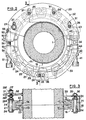
- Fig. 1 part of a blast furnace downspout, comprising an upper element 1 which is in fact the lower cone and a lower element 2 in the shape of a T, or dolphin, on which is fixed a nozzle 3.
- the following device the invention is used to assemble the conical element 1 and the dolphin 2.
- This device mainly comprises two flanges 11, 12 fixed respectively to the ends of elements 1 and 2 and having sealing facing surfaces 13, 14 plane and horizontal, and opposite or frustoconical outer surfaces 15, 16. These two flanges therefore form an angle with a plane perpendicular to the axis of the elements 1 and 2. They cooperate with a clamp 20 which is best seen in FIGS. 2 and 3 and which is constituted by several jaws 21, the internal surface of which delimits two frustoconical surfaces 22, 23 or delimiting a corner so as to be able to cooperate with the surfaces 15, 16 and carry out the tightening of the flanges. These jaws are connected by links 24 and articulated on the latter by pins 25. The surfaces of the flanges and the jaws are preferably subjected to a sulfinusation treatment or the like intended to give them the appropriate surface condition.
- the collar 20 is suspended from a support 30 by rods 26 which constitute extensions of some of the articulation axes 25, comprising threaded upper parts 27 received in slots 31 of oblong shape of the support and associated with nuts 28 3 , 28 b , 28 °.
- the support 30 is constituted by a plate 32 of partially annular shape, welded to the upper element 1 and which extends over an angle at the center less than 180 °.
- the slots 31 receiving the rods 26 have an oblong shape and are approximately parallel to one another and approximately parallel to the direction of release of the lower element 2.
- an arm 33 articulated around 'a vertical axis, this arm extending over an angle at the center of about 90 ° and supporting the collar 20 in the vicinity of its free end by means of a rod 35 received in a lumen 36 also of oblong shape but s' extending approximately perpendicularly to the slots 31 when the collar is in the closed position as shown in FIG. 2.
- This arm generally has a section in C, as shown in FIG. 3.
- the clamping and loosening means of the collar comprise two sets 40, 50 with screws and nuts, diametrically opposite and whose screws 41, 51 are oriented, in the clamping position, approximately parallel to the slots 31.
- the first set 40 is placed in the vicinity of the articulation 34 between the two parts of the support and comprises the screw 41 and a nut 42 delimited by a jaw 43.
- the screw 41 is rotatably mounted in a jaw element 44.
- the jaws 43, 44 are not well heard connected to no link but by the screw 41 and the nut 42.
- the other assembly 50 with screw and nut also comprises the screw 51 and a nut 52 delimited by a jaw 53.
- the screw 51 is rotatably mounted on a jaw element 54, no link being provided between the jaws 53, 54.
- the collar 20 is therefore in fact produced in the form of two half-collars connected by the two clamping assemblies 40; 50.
- the jaw element 53 can be released from the link 55 in which it is received, this link constituting a yoke and comprising a flange 56 against which the lateral surface of the jaw 53 is normally in support.
- the jaw element 53 forming a nut can be released laterally from the link 55 from the moment when the screw 51 has been loosened over a distance at least equal to the height h of the flange 56.
- the two sets of screws and nuts are loosened, the screw 51 being loosened enough to be able to release the nut 52, 53 from its housing.
- the arm 33 can be released by rotation about the axis 34 and the collar 20 open as shown in this same Fig. 4.
- the flanges are no longer clamped against each other and the lower element can be separated from the upper element.
- the collar can be opened over 180 ° thanks to the realization of the support in two parts hinged one on the other.
- Reassembly is carried out just as simply and quickly since it suffices to bring the two flanges into moon contact against each other, to put the collar 20 and the nut 52, 53 in place, then to tighten the two screws 41 , 51 to obtain automatic centering and a solid connection between the two elements.
- the device can undergo various modifications, a single set of screw and quick-release nut similar to the assembly 50 can, where appropriate, be provided, or the support and suspension means of the collar can undergo various modifications.
Landscapes
- Engineering & Computer Science (AREA)
- General Engineering & Computer Science (AREA)
- Chemical & Material Sciences (AREA)
- Materials Engineering (AREA)
- Metallurgy (AREA)
- Organic Chemistry (AREA)
- Manufacturing & Machinery (AREA)
- Mechanical Engineering (AREA)
- Flanged Joints, Insulating Joints, And Other Joints (AREA)
- Quick-Acting Or Multi-Walled Pipe Joints (AREA)
- Blast Furnaces (AREA)
- Clamps And Clips (AREA)
- Mutual Connection Of Rods And Tubes (AREA)
- Wind Motors (AREA)
- Automatic Cycles, And Cycles In General (AREA)
Applications Claiming Priority (2)
| Application Number | Priority Date | Filing Date | Title |
|---|---|---|---|
| FR7729505 | 1977-09-30 | ||
| FR7729505A FR2404793A1 (fr) | 1977-09-30 | 1977-09-30 | Dispositif d'assemblage, notamment entre deux troncons d'une descente de vent de haut-fourneau |
Publications (2)
| Publication Number | Publication Date |
|---|---|
| EP0001527A1 EP0001527A1 (fr) | 1979-04-18 |
| EP0001527B1 true EP0001527B1 (fr) | 1980-08-06 |
Family
ID=9195978
Family Applications (1)
| Application Number | Title | Priority Date | Filing Date |
|---|---|---|---|
| EP78400115A Expired EP0001527B1 (fr) | 1977-09-30 | 1978-09-27 | Dispositif d'assemblage, notamment entre deux tronçons d'une descente de vent de haut-fourneau |
Country Status (10)
| Country | Link |
|---|---|
| US (1) | US4191410A (cg-RX-API-DMAC7.html) |
| EP (1) | EP0001527B1 (cg-RX-API-DMAC7.html) |
| JP (1) | JPS5457409A (cg-RX-API-DMAC7.html) |
| BE (1) | BE870742A (cg-RX-API-DMAC7.html) |
| DE (1) | DE2860120D1 (cg-RX-API-DMAC7.html) |
| ES (1) | ES473812A1 (cg-RX-API-DMAC7.html) |
| FR (1) | FR2404793A1 (cg-RX-API-DMAC7.html) |
| GB (1) | GB2005784B (cg-RX-API-DMAC7.html) |
| IT (2) | IT1108405B (cg-RX-API-DMAC7.html) |
| LU (1) | LU80294A1 (cg-RX-API-DMAC7.html) |
Families Citing this family (24)
| Publication number | Priority date | Publication date | Assignee | Title |
|---|---|---|---|---|
| JPS55112182U (cg-RX-API-DMAC7.html) * | 1979-02-01 | 1980-08-07 | ||
| DE3048903C2 (de) * | 1980-12-23 | 1983-01-20 | Leybold-Heraeus GmbH, 5000 Köln | Spannvorrichtung zur Verbindung eines Flanschpaares |
| JPH0416049Y2 (cg-RX-API-DMAC7.html) * | 1986-03-06 | 1992-04-10 | ||
| DE3633380A1 (de) * | 1986-10-01 | 1988-04-14 | Kernforschungsz Karlsruhe | Spannvorrichtung zum verbinden zweier flansche |
| US4901307A (en) * | 1986-10-17 | 1990-02-13 | Qualcomm, Inc. | Spread spectrum multiple access communication system using satellite or terrestrial repeaters |
| JPH0411989U (cg-RX-API-DMAC7.html) * | 1990-05-22 | 1992-01-30 | ||
| FR2697893B1 (fr) * | 1992-11-06 | 1995-01-27 | Goavec Sa | Collier pour le raccordement amovible de deux canalisations. |
| DE4313518A1 (de) * | 1993-04-24 | 1994-11-03 | Georg Prof Dipl Ing Guertler | System zum Empfang codierter Fernsehsendungen gegen Bezahlung |
| DE19627841A1 (de) * | 1995-08-14 | 1997-02-20 | Heinrich Fend | Vorrichtung zum Gegeneinanderpressen von zwei Flanschen einer Rohrverbindung |
| US6367843B1 (en) * | 1997-02-03 | 2002-04-09 | Automated Connectors Holdings, L.B. | Remote operable fastener and method of use |
| DE19750251C2 (de) * | 1997-11-13 | 2003-04-30 | Karl Weinhold | Kettenförmige Rohrschelle |
| NO306917B1 (no) | 1998-07-13 | 2000-01-10 | Abb Offshore Technology As | Leddet klammerkopling |
| EP1199521A1 (de) * | 2000-10-16 | 2002-04-24 | Siemens Aktiengesellschaft | Gasturbine und Verfahren zur Dämpfung von Schwingungen einer Ringbrennkammer einer Gasturbine |
| NO328283B1 (no) * | 2004-05-26 | 2010-01-25 | Fmc Kongsberg Subsea As | Rorklemme |
| NO20083826L (no) * | 2008-09-08 | 2010-03-09 | Tdw Offshore Services As | Anordning ved rorklammer ("Pipe clamp") |
| US8657255B2 (en) * | 2010-04-08 | 2014-02-25 | Honeywell International Inc. | Aircraft valve assemblies including clamp-specific baulking tab arrays and methods for the manufacture thereof |
| DE202010012940U1 (de) * | 2010-05-12 | 2011-01-27 | Georg Springmann Industrie- Und Bergbautechnik Gmbh | Rohr- und Schlauchkupplung |
| US9291290B2 (en) | 2012-05-21 | 2016-03-22 | Havaco Technologies | Foldable HVAC conduit and duct collar |
| ES2593752T3 (es) * | 2012-06-14 | 2016-12-13 | Norma Germany Gmbh | Abrazadera de perfil |
| CN104164523B (zh) * | 2014-07-29 | 2015-12-30 | 广东韶钢工程技术有限公司 | 一种快速拆装高炉吹管打紧斜楔工具及其使用方法 |
| US9709198B1 (en) * | 2016-11-29 | 2017-07-18 | General Electric Company | Clamped connector systems for use with piping assemblies |
| CN109990150A (zh) * | 2017-12-29 | 2019-07-09 | 巴斯夫聚氨酯特种产品(中国)有限公司 | 管道连接结构及化工设备的管道系统 |
| US11384877B2 (en) * | 2019-01-25 | 2022-07-12 | Raytheon Technologies Corporation | Retaining assembly for a gas turbine engine |
| CN113757461A (zh) * | 2021-02-07 | 2021-12-07 | 上海威逊机械连接件有限公司 | 快装接头 |
Family Cites Families (9)
| Publication number | Priority date | Publication date | Assignee | Title |
|---|---|---|---|---|
| US2640717A (en) * | 1949-07-26 | 1953-06-02 | Emerson Scheuring Tank And Mfg | Separable pressure vessel quick clamp |
| US2895748A (en) * | 1957-09-12 | 1959-07-21 | Oldham Charles Albert Edward | Band type clamp for flanged pipes |
| GB854629A (en) * | 1958-04-17 | 1960-11-23 | Rolls Royce | Pipe coupling |
| US3070388A (en) * | 1960-02-24 | 1962-12-25 | Gen Motors Corp | Engine ring clamp having hinge means to permit outward radial movement of the clamp |
| FR1304341A (fr) * | 1961-10-23 | 1962-09-21 | Barmag Barmer Maschf | Dispositif d'accouplement destiné à l'assemblage des brides de raccordement d'une filière d'extrusion et du cylindre de presses à vis sans fin |
| US3661409A (en) * | 1969-08-14 | 1972-05-09 | Gray Tool Co | Multi-segment clamp |
| US3843167A (en) * | 1973-01-31 | 1974-10-22 | B Gronstedt | Hydraulically actuated pipe coupling |
| CH559333A5 (cg-RX-API-DMAC7.html) * | 1973-03-27 | 1975-02-28 | Fend Heinrich | |
| US4079970A (en) * | 1976-09-21 | 1978-03-21 | Tri-Canada Cherry-Burrell Ltd. | Pipe switching station clamp |
-
1977
- 1977-09-30 FR FR7729505A patent/FR2404793A1/fr active Granted
-
1978
- 1978-09-19 GB GB7837264A patent/GB2005784B/en not_active Expired
- 1978-09-25 BE BE190690A patent/BE870742A/xx not_active IP Right Cessation
- 1978-09-27 IT IT69224/78A patent/IT1108405B/it active
- 1978-09-27 DE DE7878400115T patent/DE2860120D1/de not_active Expired
- 1978-09-27 EP EP78400115A patent/EP0001527B1/fr not_active Expired
- 1978-09-27 IT IT7853731U patent/IT7853731V0/it unknown
- 1978-09-28 LU LU80294A patent/LU80294A1/xx unknown
- 1978-09-29 JP JP12030678A patent/JPS5457409A/ja active Granted
- 1978-09-29 ES ES473812A patent/ES473812A1/es not_active Expired
- 1978-09-29 US US05/946,735 patent/US4191410A/en not_active Expired - Lifetime
Also Published As
| Publication number | Publication date |
|---|---|
| JPS5457409A (en) | 1979-05-09 |
| GB2005784B (en) | 1982-03-03 |
| ES473812A1 (es) | 1979-10-16 |
| BE870742A (fr) | 1979-03-26 |
| IT7869224A0 (it) | 1978-09-27 |
| JPS6120605B2 (cg-RX-API-DMAC7.html) | 1986-05-23 |
| EP0001527A1 (fr) | 1979-04-18 |
| FR2404793B1 (cg-RX-API-DMAC7.html) | 1981-12-18 |
| US4191410A (en) | 1980-03-04 |
| GB2005784A (en) | 1979-04-25 |
| IT7853731V0 (it) | 1978-09-27 |
| FR2404793A1 (fr) | 1979-04-27 |
| IT1108405B (it) | 1985-12-09 |
| DE2860120D1 (en) | 1980-11-27 |
| LU80294A1 (fr) | 1979-03-16 |
Similar Documents
| Publication | Publication Date | Title |
|---|---|---|
| EP0001527B1 (fr) | Dispositif d'assemblage, notamment entre deux tronçons d'une descente de vent de haut-fourneau | |
| EP0027406B1 (fr) | Raccord de canalisation comprenant un collier à chaîne | |
| EP0810944A1 (fr) | Axe de blocage rapide destine a etre utilise sur un cycle | |
| FR2721391A1 (fr) | Equipement portatif pour immobiliser les armes à feu individuelles. | |
| EP3475141B1 (fr) | Ensemble de plaquettes de frein | |
| FR2771318A1 (fr) | Tronconneuse de rail | |
| WO2006134284A1 (fr) | Dispositif de centrage et de serrage de pieces tubulaires | |
| FR2686386A1 (fr) | Dispositif de serrage de vis. | |
| FR2958568A1 (fr) | Installation permettant de decouper dans une bande de tole deux flans et d'evacuer ceux-ci a chaque operation de decoupe | |
| EP1452749A1 (fr) | Dispositif de jonction articulée | |
| EP1111290A1 (fr) | Dispositif de fixation d'un équipement sur un mât | |
| FR2472099A1 (fr) | Moyens d'assemblage de deux grosses pieces munies de brides | |
| FR2525930A1 (fr) | Dispositif d'aspiration de fumees | |
| FR2495711A1 (fr) | Dispositif de palier pour centrifugeuse | |
| FR2916718A1 (fr) | Dispositif mecanique de reglage d'un balancier d'appui et de guidage d'un cable aerien d'une installation de remontee mecanique | |
| FR2654798A1 (fr) | Outil pour la mise en place d'un embout a une extremite d'un tube. | |
| FR2680120A1 (fr) | Procede et dispositif de revetement de surfaces munies de perforations par projection, notamment pour la metallisation par du plasma. | |
| FR2638817A1 (fr) | Dispositif de fixation d'un ensemble lampe-reflecteur dans une ouverture formee dans une paroi | |
| EP0912275B1 (fr) | Dispositif de bridage d'une table de coulee d'une machine de coulee continue verticale de pieces, en particulier de tubes, en fonte | |
| FR2826629A1 (fr) | Dispositif pour la mise en place et/ou la depose d'un pod de propulsion, orientable, d'un navire | |
| FR2613769A1 (fr) | Convertisseur catalytique pour gaz d'echappement de vehicules | |
| EP0345407B1 (fr) | Procédé de réglage de débit dans une vanne et vanne pour la mise en oeuvre de ce procédé | |
| FR2510388A3 (fr) | Dispositif d'acheminement de jet d'eau dans une machine a laver la vaisselle | |
| EP0623706A1 (fr) | Dispositif d'aiguillage pour convoyeurs suspendus | |
| EP0841214B1 (fr) | Vis de réglage de position sans jeu pour dispositif d'éclairage ou de signalisation pour véhicule automobile |
Legal Events
| Date | Code | Title | Description |
|---|---|---|---|
| PUAI | Public reference made under article 153(3) epc to a published international application that has entered the european phase |
Free format text: ORIGINAL CODE: 0009012 |
|
| AK | Designated contracting states |
Designated state(s): DE NL |
|
| 17P | Request for examination filed | ||
| GRAA | (expected) grant |
Free format text: ORIGINAL CODE: 0009210 |
|
| AK | Designated contracting states |
Designated state(s): DE NL |
|
| REF | Corresponds to: |
Ref document number: 2860120 Country of ref document: DE Date of ref document: 19801127 |
|
| PGFP | Annual fee paid to national office [announced via postgrant information from national office to epo] |
Ref country code: DE Payment date: 19930818 Year of fee payment: 16 |
|
| PGFP | Annual fee paid to national office [announced via postgrant information from national office to epo] |
Ref country code: NL Payment date: 19930930 Year of fee payment: 16 |
|
| PG25 | Lapsed in a contracting state [announced via postgrant information from national office to epo] |
Ref country code: NL Effective date: 19950401 |
|
| NLV4 | Nl: lapsed or anulled due to non-payment of the annual fee | ||
| PG25 | Lapsed in a contracting state [announced via postgrant information from national office to epo] |
Ref country code: DE Effective date: 19950601 |
|
| PLBE | No opposition filed within time limit |
Free format text: ORIGINAL CODE: 0009261 |
|
| STAA | Information on the status of an ep patent application or granted ep patent |
Free format text: STATUS: NO OPPOSITION FILED WITHIN TIME LIMIT |