EP0000296B1 - Dispositif de transmission pour véhicules notamment pour chariots élévateurs - Google Patents
Dispositif de transmission pour véhicules notamment pour chariots élévateurs Download PDFInfo
- Publication number
- EP0000296B1 EP0000296B1 EP78400004A EP78400004A EP0000296B1 EP 0000296 B1 EP0000296 B1 EP 0000296B1 EP 78400004 A EP78400004 A EP 78400004A EP 78400004 A EP78400004 A EP 78400004A EP 0000296 B1 EP0000296 B1 EP 0000296B1
- Authority
- EP
- European Patent Office
- Prior art keywords
- drive
- wheels
- vehicle
- wheel
- mechanisms
- Prior art date
- Legal status (The legal status is an assumption and is not a legal conclusion. Google has not performed a legal analysis and makes no representation as to the accuracy of the status listed.)
- Expired
Links
Images
Classifications
-
- B—PERFORMING OPERATIONS; TRANSPORTING
- B60—VEHICLES IN GENERAL
- B60K—ARRANGEMENT OR MOUNTING OF PROPULSION UNITS OR OF TRANSMISSIONS IN VEHICLES; ARRANGEMENT OR MOUNTING OF PLURAL DIVERSE PRIME-MOVERS IN VEHICLES; AUXILIARY DRIVES FOR VEHICLES; INSTRUMENTATION OR DASHBOARDS FOR VEHICLES; ARRANGEMENTS IN CONNECTION WITH COOLING, AIR INTAKE, GAS EXHAUST OR FUEL SUPPLY OF PROPULSION UNITS IN VEHICLES
- B60K17/00—Arrangement or mounting of transmissions in vehicles
- B60K17/34—Arrangement or mounting of transmissions in vehicles for driving both front and rear wheels, e.g. four wheel drive vehicles
- B60K17/342—Arrangement or mounting of transmissions in vehicles for driving both front and rear wheels, e.g. four wheel drive vehicles having a longitudinal, endless element, e.g. belt or chain, for transmitting drive to wheels
-
- B—PERFORMING OPERATIONS; TRANSPORTING
- B60—VEHICLES IN GENERAL
- B60K—ARRANGEMENT OR MOUNTING OF PROPULSION UNITS OR OF TRANSMISSIONS IN VEHICLES; ARRANGEMENT OR MOUNTING OF PLURAL DIVERSE PRIME-MOVERS IN VEHICLES; AUXILIARY DRIVES FOR VEHICLES; INSTRUMENTATION OR DASHBOARDS FOR VEHICLES; ARRANGEMENTS IN CONNECTION WITH COOLING, AIR INTAKE, GAS EXHAUST OR FUEL SUPPLY OF PROPULSION UNITS IN VEHICLES
- B60K1/00—Arrangement or mounting of electrical propulsion units
- B60K1/02—Arrangement or mounting of electrical propulsion units comprising more than one electric motor
-
- F—MECHANICAL ENGINEERING; LIGHTING; HEATING; WEAPONS; BLASTING
- F16—ENGINEERING ELEMENTS AND UNITS; GENERAL MEASURES FOR PRODUCING AND MAINTAINING EFFECTIVE FUNCTIONING OF MACHINES OR INSTALLATIONS; THERMAL INSULATION IN GENERAL
- F16H—GEARING
- F16H37/00—Combinations of mechanical gearings, not provided for in groups F16H1/00 - F16H35/00
- F16H37/02—Combinations of mechanical gearings, not provided for in groups F16H1/00 - F16H35/00 comprising essentially only toothed or friction gearings
- F16H37/06—Combinations of mechanical gearings, not provided for in groups F16H1/00 - F16H35/00 comprising essentially only toothed or friction gearings with a plurality of driving or driven shafts; with arrangements for dividing torque between two or more intermediate shafts
- F16H37/08—Combinations of mechanical gearings, not provided for in groups F16H1/00 - F16H35/00 comprising essentially only toothed or friction gearings with a plurality of driving or driven shafts; with arrangements for dividing torque between two or more intermediate shafts with differential gearing
-
- B—PERFORMING OPERATIONS; TRANSPORTING
- B60—VEHICLES IN GENERAL
- B60L—PROPULSION OF ELECTRICALLY-PROPELLED VEHICLES; SUPPLYING ELECTRIC POWER FOR AUXILIARY EQUIPMENT OF ELECTRICALLY-PROPELLED VEHICLES; ELECTRODYNAMIC BRAKE SYSTEMS FOR VEHICLES IN GENERAL; MAGNETIC SUSPENSION OR LEVITATION FOR VEHICLES; MONITORING OPERATING VARIABLES OF ELECTRICALLY-PROPELLED VEHICLES; ELECTRIC SAFETY DEVICES FOR ELECTRICALLY-PROPELLED VEHICLES
- B60L2200/00—Type of vehicles
- B60L2200/40—Working vehicles
- B60L2200/42—Fork lift trucks
-
- Y—GENERAL TAGGING OF NEW TECHNOLOGICAL DEVELOPMENTS; GENERAL TAGGING OF CROSS-SECTIONAL TECHNOLOGIES SPANNING OVER SEVERAL SECTIONS OF THE IPC; TECHNICAL SUBJECTS COVERED BY FORMER USPC CROSS-REFERENCE ART COLLECTIONS [XRACs] AND DIGESTS
- Y10—TECHNICAL SUBJECTS COVERED BY FORMER USPC
- Y10T—TECHNICAL SUBJECTS COVERED BY FORMER US CLASSIFICATION
- Y10T74/00—Machine element or mechanism
- Y10T74/19—Gearing
- Y10T74/19014—Plural prime movers selectively coupled to common output
Definitions
- the invention due to the collaboration of Mr. Georges ITEY-BERNARD relates to a device for transmitting movement to the wheels of a vehicle such as a forklift with driving axles, which comprises at least one engine generating the driving force and one speed reduction mechanism, controlling the rotation of a driving wheel of the vehicle.
- the transmission devices which on certain vehicles control each drive wheel individually can be classified into two distinct types: those which include a planetary reduction gear on the one hand, and on the other hand, those which include a reduction device with belts and bevel pulleys .
- a control mechanism of a drive wheel of a forklift truck not only have a longevity greater than that of conventional mechanisms, but also that it is produced in such a way that all of the reduction gears is housed near the rim of the wheel, that the brakes, which are an integral part of the mechanism, are very accessible, to facilitate their maintenance and that, in general, this mechanism is relatively inexpensive, and is characterized by its simplicity and the ease with which it can be dismantled and reassembled.
- DTOS publication 1 580 064 KESSLER discloses a vehicle transmission (such as a crane), the transmission members of which are arranged at the periphery of the chassis.
- two engines drive reduction mechanisms associated with the driving streets of the vehicle by means of a return mechanism.
- the return mechanism which must be associated with one or the other motor allows a distribution of the driving power.
- Such a transmission is suitable for vehicles whose wheels are in contact with guide rails located on either side of a pit capable of receiving the protuberance due to the presence of the drive motor, this transmission is also suitable for vehicles whose the wheels are in contact with guide rails and the chassis of which is made up of assembled metal profiles which delimit a well capable of receiving the drive motor.
- Such a device partly occupies the central part of the vehicle and cannot be adapted to vehicles with steerable wheels of simplified design such as forklifts on which neither the use of drive shafts nor the use of gaskets is desired. trans. .. articulated ssion.
- U.S. Patent 2,317,623 LEE is a device for driving the wheels of a vehicle, using two motors respectively associated with two lines of drive shafts arranged at the periphery of the chassis of the vehicle.
- Such a device presupposes the simultaneous synchronous operation of the two motors and is not suitable for vehicles whose speed of movement is to be modified by stopping one of the motors.
- the subject of the invention is a simplified transmission device with two motors whose coupling, or separate operation, allows the vehicle to evolve in the desired speed range.
- a driving element of one of the wheels ensures the transmission of the driving force from an input or driving element of the mechanism, to an output or driven element of this mechanism, which are respectively driven. by a transmission member, while a brake of said drive element slows down said wheel.
- the transmission device thus produced allows the elimination of conventional drive axles consisting of wheel shafts associated with a differential mechanism.
- Such a transmission device is therefore particularly suitable for driving forklifts or other vehicles, the load-carrying device of which can occupy a horizontal storage position between the front and rear axles.
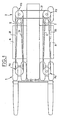
- FIG. 1 is a plan view of the chassis of the vehicle on which the transmission device components.
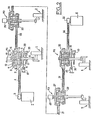
- Figure 2 is a view developed as a transmission device.
- the vehicle is a forklift of the type comprising four driving wheels forming part of the front 1 and rear 2 axles.
- a motor (which can be electric) I, generator of the driving force, (it should be noted that this motor can be just as thermal or hydraulic) is supplied by a battery B and is clamped on the chassis of the carriage. It causes directly a pulley 3.
- the latter receives a flexible transmission member such as a driving belt 4, which drives a pulley constituting the input element 5 of a speed-reducing mechanism designated as a whole by the reference R1.
- the reduction gear R1 that we are going to describe now is associated with the left front wheel of axle 1.
- reduction mechanisms R2, R3, R4, of the same structure as the mechanism R1 are respectively associated with the other wheels of the vehicle such as the left and right rear wheels of the rear axle 2 and the right front wheel of the front axle 1.
- the reduction mechanisms R2, R3, R4 therefore need not be described.
- the mechanism R1 shown in more detail in FIG. 2 essentially comprises an input element 5, the external part of which is produced in the form of a pulley, called by convention pulley, and the internal part of which carries the toothing of a planetary ring 7 with which a satellite 8 meshes.
- the satellites 8 and 9 are fixed by means of axes to a planet carrier 13.
- the latter consists of two flanges 14, 15 supporting the axes of satellites 8, 9.
- Axes 16, 17 constitute the bearing bearings of the planetary rings 11, 7 and are rigidly connected to the flanges 14, 15 while extending axially towards the outside of the mechanism, in order to carry out the driving of a pump.
- auxiliary 18 and bevel gear 19 driving the left front wheel of the axle 1.
- the pump 18, of small displacement, supplies a hydraulic circuit to the auxiliaries such as the power steering and the control circuit of the various disc brakes ; the pump 18 is preferably mounted on the mechanism R1 because the latter is in constant connection with the motor I, the tensioning of which is uninterrupted during the movements of handling and movement of the carriage.
- the reduction mechanisms R2 and R3 drive in an analogous manner. to that of mechanism R1, a pump 28 and 48.
- the kinematics of the mechanism show that the direction of rotation of the pulley 5 is opposite to the direction of rotation of the pulley 12.
- the speed of the planet carrier is proportional to the speed of the corresponding wheel of the vehicle.
- the speed of rotation of the pulley 5 is equal to the speed of rotation of the pulley 12 when the planet carrier is stopped.
- the driven pulley 12 of the mechanism R1 is mechanically connected to the driving pulley 20 of the mechanism R2 by means of the transmission member represented in the form of a belt 25.
- the driven pulley 26 of the mechanism R2 is mechanically connected to the driving pulley 27 of the mechanism R3 by means of a belt 21.
- the driven pulley 29 of the mechanism R3 is mechanically connected to the driving pulley 30 of the mechanism R4 by means of a belt 31.
- the driven pulley 32 of the mechanism R4 is mechanically connected to the driving pulley 33 of an electric motor II, supplied by the battery B, by means of a belt 34.
- the electric motor It is also clamped on the chassis of the carriage.
- connections shown make it possible to connect: the left front wheel to the left rear wheel by the belt 25; the left rear wheel to the right rear wheel by the belt 21; the right rear wheel to the right front wheel by the belt 31.
- the advantage of such kinematics lies in the fact that any connection between the front wheels of the vehicle is avoided.
- the speed of rotation of the driving pulleys is transmitted to the driven pulleys with change of the direction of rotation of the pulleys.
- the motor Il which is not supplied will therefore rotate at the speed of the motor I if the pulleys 3 and 33 are of the same diameter.
- the inertia of the engine It generates a reaction torque on all the planet carriers of the four mechanisms R1, R2, R3, R4. This engine reaction torque It will generally be insufficient to start the truck. However, the starting of the carriage will be obtained as a result of the blocking of the driven pulley 32 of the mechanism R4 under the action of a disc brake 35 whose braking force is applied to a disc 36 secured to the driven pulley 32 .
- the driving pulley 5 of the mechanism R1 can be immobilized by a disc brake 37 whose braking force is applied to a disc 38 integral with the driving pulley 5.
- a numerical example based on a rotation speed of 3000 rpm of the motor and a rotation speed of 375 rpm for each planet carrier, makes it possible to show very simply that the second motor remains stationary when the carriage is moving at half speed on flat ground.
- the driving pulleys 5 and 32 of the mechanisms R1 and R4 rotate at the speed of the motors, equal, according to the nonlimiting example, to 3000 rpm. If the speed of rotation of the planet carrier is 750 rpm when the carriage is moving at full speed in a straight line, a simple demonstration shows that the driven pulley 26 and the driving pulley 27 are at zero speed. This advantageous property of the transmission therefore makes it possible to stop the pumps 28 and 48 mounted on the reduction mechanisms R2 and R3.
- the pumps 28 and 48 provide the elevation control of a load-bearing plate linked to the chassis of the carriage, it can be seen that it is impossible to maneuver the load-bearing plate in a straight line at full translation speed.
- the trolley therefore provides better safety in use and allows a substantial saving of energy due to the automatic stopping of the pumps 28 and 48. It is nevertheless accepted that the lifting of the load-carrying plate can take place up to that the carriage reaches half its maximum speed with a single motor and that the rapid lifting of the load-bearing plate can take place when the carriage is stopped, the two motors i, Il turning as before at the same speed and in the opposite direction.
- the direction of travel is inverted automatically by cutting off the supply to motor I and by supplying motor II, previously stationary, after reversing its direction of rotation. This change in the supply of the motors can be carried out even when the carriage is moving forward, and is not detrimental to their proper functioning.
- the direction of torque transmission from engine II, to engine I, ensures reverse starting after application of brake 37.
- the transmission also makes it possible to economically obtain numerous transmission ratios which are close to one another without appreciable modification of the acceleration of the vehicle, just as a substantially more complicated electronic engine regulation device would do.
- the device illustrated by way of example is not limiting, it may in particular use reduction mechanisms whose gear satellites are replaced by cylindrical friction rollers movable between coaxial tracks.
- the brakes used 39, 40 and 35, 37 will preferably be disc brakes because the transmission lends itself to it by the pre sence of vertical shafts 17 linking the reduction mechanisms to the bevel gears 19.
- the shaft 17 has a speed that is sufficiently multiplied to allow the use of small discs and lockable brakes outside the corresponding wheel to be braked.
Landscapes
- Engineering & Computer Science (AREA)
- Mechanical Engineering (AREA)
- Chemical & Material Sciences (AREA)
- Combustion & Propulsion (AREA)
- Transportation (AREA)
- General Engineering & Computer Science (AREA)
- Arrangement Of Transmissions (AREA)
- Forklifts And Lifting Vehicles (AREA)
- Electric Propulsion And Braking For Vehicles (AREA)
- Arrangement And Mounting Of Devices That Control Transmission Of Motive Force (AREA)
- Arrangement And Driving Of Transmission Devices (AREA)
- Retarders (AREA)
Applications Claiming Priority (2)
| Application Number | Priority Date | Filing Date | Title |
|---|---|---|---|
| FR7719912 | 1977-06-29 | ||
| FR7719912A FR2408480A1 (fr) | 1977-06-29 | 1977-06-29 | Dispositif de transmission pour vehicule notamment pour chariot elevateur |
Publications (2)
| Publication Number | Publication Date |
|---|---|
| EP0000296A1 EP0000296A1 (fr) | 1979-01-10 |
| EP0000296B1 true EP0000296B1 (fr) | 1980-08-20 |
Family
ID=9192711
Family Applications (1)
| Application Number | Title | Priority Date | Filing Date |
|---|---|---|---|
| EP78400004A Expired EP0000296B1 (fr) | 1977-06-29 | 1978-06-01 | Dispositif de transmission pour véhicules notamment pour chariots élévateurs |
Country Status (8)
| Country | Link |
|---|---|
| US (1) | US4245712A (it) |
| EP (1) | EP0000296B1 (it) |
| JP (1) | JPS5418535A (it) |
| DE (1) | DE2860224D1 (it) |
| DK (1) | DK285678A (it) |
| ES (1) | ES470726A1 (it) |
| FR (1) | FR2408480A1 (it) |
| IT (1) | IT1109729B (it) |
Families Citing this family (6)
| Publication number | Priority date | Publication date | Assignee | Title |
|---|---|---|---|---|
| US5527225A (en) * | 1992-12-29 | 1996-06-18 | Dana Corporation | Full time four-wheel drive system |
| US7294082B2 (en) * | 2004-12-21 | 2007-11-13 | Chrysler Llc | Powertrain arrangement for a skid-steer vehicle |
| US20060169514A1 (en) * | 2004-12-21 | 2006-08-03 | Lim Stephen T | Axle arrangement for a vehicle |
| CN1884806A (zh) * | 2005-06-24 | 2006-12-27 | 刘子安 | 高节能汽车发动机 |
| US10399437B2 (en) * | 2016-09-06 | 2019-09-03 | Joy Global Underground Mining Llc | Coupled compound planetary transmission for a wheel unit |
| SK500342017A3 (sk) * | 2017-05-05 | 2018-11-05 | Kovaco Spol. S R. O. | Usporiadanie na pohon všetkých kolies s nízkym vstupným krútiacom momentom najmä pre šmykom riadené nakladače |
Family Cites Families (14)
| Publication number | Priority date | Publication date | Assignee | Title |
|---|---|---|---|---|
| US1900470A (en) * | 1931-02-27 | 1933-03-07 | Hubert P Smith | Automotive system |
| US2257772A (en) * | 1932-04-07 | 1941-10-07 | Austin M Wolf | Motor vehicle propulsion |
| US2036153A (en) * | 1934-09-18 | 1936-03-31 | Robert J Lewis | Portable container |
| US2317623A (en) * | 1941-03-14 | 1943-04-27 | Joy Mfg Co | Vehicle drive |
| GB608592A (en) * | 1945-04-04 | 1948-09-17 | Henry Carl Harbers | Improved motor vehicle chassis particularly for armoured vehicles |
| CH356972A (de) * | 1955-09-23 | 1961-09-15 | Roller Gear Company Inc | Kugelreibungsgetriebe |
| GB878075A (en) * | 1958-06-24 | 1961-09-27 | Achille Carlos Sampietro | Improvements relating to belt and pulley transmissions |
| US3194087A (en) * | 1961-04-28 | 1965-07-13 | Volvo Ab | Drive system for vehicles |
| US3255840A (en) * | 1962-08-08 | 1966-06-14 | Tangen Anthony | Motor vehicle with four driven and steered wheels |
| FR1488285A (fr) * | 1966-04-01 | 1967-07-13 | Panhard & Levassor Const Mec | Perfectionnements apportés aux véhicules automobiles à quatre roues motrices |
| DE1580064A1 (de) * | 1966-04-29 | 1970-09-24 | Kessler & Co Gmbh | Fahrzeugkran mit Radantrieb durch einen auf dem Ober- oder/und Unterwagen angeordneten Motor |
| AU413900B2 (en) * | 1967-06-07 | 1971-05-31 | Owens Illinois, Inc | Positive traction system for vehicles |
| US3804190A (en) * | 1972-10-10 | 1974-04-16 | Towmotor Corp | Auxiliary-powered wheel unit for dirigible wheel applications |
| DE2503762A1 (de) * | 1975-01-30 | 1976-08-05 | Grueko Konstruktionen Gmbh | Planetengetriebe |
-
1977
- 1977-06-29 FR FR7719912A patent/FR2408480A1/fr active Granted
-
1978
- 1978-06-01 EP EP78400004A patent/EP0000296B1/fr not_active Expired
- 1978-06-01 DE DE7878400004T patent/DE2860224D1/de not_active Expired
- 1978-06-05 IT IT68292/78A patent/IT1109729B/it active
- 1978-06-13 ES ES470726A patent/ES470726A1/es not_active Expired
- 1978-06-26 DK DK285678A patent/DK285678A/da not_active Application Discontinuation
- 1978-06-27 JP JP7708878A patent/JPS5418535A/ja active Pending
- 1978-06-28 US US05/919,903 patent/US4245712A/en not_active Expired - Lifetime
Also Published As
| Publication number | Publication date |
|---|---|
| FR2408480A1 (fr) | 1979-06-08 |
| IT1109729B (it) | 1985-12-23 |
| DE2860224D1 (en) | 1980-12-04 |
| IT7868292A0 (it) | 1978-06-05 |
| DK285678A (da) | 1978-12-30 |
| JPS5418535A (en) | 1979-02-10 |
| US4245712A (en) | 1981-01-20 |
| ES470726A1 (es) | 1979-01-16 |
| EP0000296A1 (fr) | 1979-01-10 |
| FR2408480B1 (it) | 1980-03-21 |
Similar Documents
| Publication | Publication Date | Title |
|---|---|---|
| EP0756675B1 (fr) | Transmission mecanique a variation continue automatique et son procede de mise en action | |
| FR2812922A1 (fr) | Dispositif de transmission a rapports variables | |
| FR2538488A1 (fr) | Groupe d'entrainement pour vehicule automobile, comportant un axe principal geometrique pour l'arbre principal du moteur et un axe principal parallele pour l'arbre de sortie d'une boite de vitesses du type a trains planetaires | |
| FR2691778A1 (fr) | Transmission à différentiel, à fonction de changement de vitesse. | |
| EP0000296B1 (fr) | Dispositif de transmission pour véhicules notamment pour chariots élévateurs | |
| FR2645932A1 (fr) | Transmission hydrostatique-mecanique a action progressive a derivation de puissance | |
| FR2580244A1 (fr) | Dispositif automatique pour deplacer et notamment faire tourner un vehicule, par exemple un vehicule automobile, dans un espace restreint | |
| FR2844858A1 (fr) | Differentiel asymetrique a caractere actif pour vehicule automobile | |
| FR3121120A1 (fr) | Roue motorisée électriquement pour plateforme mobile | |
| EP0050891A1 (fr) | Moteur éolien | |
| FR2742703A1 (fr) | Transmission differentielle pour un vehicule a motorisation hybride | |
| FR2609499A1 (fr) | Groupe motopropulseur a variation continue de vitesse | |
| FR2581727A1 (fr) | Transmission continue non etagee | |
| FR2475177A1 (fr) | Transmission a deux vitesses a commande hydraulique des changements de vitesse en charge | |
| FR2796339A1 (fr) | Boite de vitesses mecanique en ligne, pour vehicule a propulsion hybride | |
| FR2797670A1 (fr) | Dispositif de transmission de mouvement a variation de vitesse | |
| EP1008481A1 (fr) | Transmission pour véhicule automobile | |
| FR2507550A1 (fr) | Tourelle motrice pour vehicule, notamment pour chariot de manutention | |
| FR2691539A1 (fr) | Banc d'essai à rouleaux pour véhicules automobiles. | |
| FR2800826A1 (fr) | Groupe motopropulseur transversal de vehicule comportant un variateur et un train epicycliadal | |
| FR2643317A1 (fr) | Vehicule a chassis extensible longitudinalement | |
| FR3101816A1 (fr) | Ensemble de transmission de puissance et véhicule comprenant cet ensemble | |
| EP1419100B1 (fr) | Treuil motorise | |
| BE505413A (it) | ||
| FR2634532A1 (fr) | Dispositif de transmission pour autoreguler la vitesse relative entre deux roues tournant dans le meme sens |
Legal Events
| Date | Code | Title | Description |
|---|---|---|---|
| PUAI | Public reference made under article 153(3) epc to a published international application that has entered the european phase |
Free format text: ORIGINAL CODE: 0009012 |
|
| AK | Designated contracting states |
Designated state(s): BE CH DE GB LU NL SE |
|
| 17P | Request for examination filed | ||
| GRAA | (expected) grant |
Free format text: ORIGINAL CODE: 0009210 |
|
| AK | Designated contracting states |
Designated state(s): BE CH DE GB LU NL SE |
|
| REF | Corresponds to: |
Ref document number: 2860224 Country of ref document: DE Date of ref document: 19801204 |
|
| PG25 | Lapsed in a contracting state [announced via postgrant information from national office to epo] |
Ref country code: LU Free format text: LAPSE BECAUSE OF NON-PAYMENT OF DUE FEES Effective date: 19810630 |
|
| PGFP | Annual fee paid to national office [announced via postgrant information from national office to epo] |
Ref country code: LU Payment date: 19830620 Year of fee payment: 6 |
|
| PGFP | Annual fee paid to national office [announced via postgrant information from national office to epo] |
Ref country code: DE Payment date: 19840326 Year of fee payment: 7 |
|
| PGFP | Annual fee paid to national office [announced via postgrant information from national office to epo] |
Ref country code: CH Payment date: 19840521 Year of fee payment: 7 |
|
| PGFP | Annual fee paid to national office [announced via postgrant information from national office to epo] |
Ref country code: SE Payment date: 19840630 Year of fee payment: 7 Ref country code: BE Payment date: 19840630 Year of fee payment: 7 |
|
| PGFP | Annual fee paid to national office [announced via postgrant information from national office to epo] |
Ref country code: NL Payment date: 19850630 Year of fee payment: 8 |
|
| PG25 | Lapsed in a contracting state [announced via postgrant information from national office to epo] |
Ref country code: SE Effective date: 19860602 |
|
| PG25 | Lapsed in a contracting state [announced via postgrant information from national office to epo] |
Ref country code: CH Effective date: 19860630 Ref country code: BE Effective date: 19860630 |
|
| BERE | Be: lapsed |
Owner name: REGIE NATIONALE DES USINES RENAULT Effective date: 19860630 Owner name: ITEY-BERNARD GEORGES Effective date: 19860630 |
|
| PG25 | Lapsed in a contracting state [announced via postgrant information from national office to epo] |
Ref country code: NL Effective date: 19870101 |
|
| NLV4 | Nl: lapsed or anulled due to non-payment of the annual fee | ||
| REG | Reference to a national code |
Ref country code: CH Ref legal event code: PL |
|
| PG25 | Lapsed in a contracting state [announced via postgrant information from national office to epo] |
Ref country code: DE Effective date: 19870303 |
|
| GBPC | Gb: european patent ceased through non-payment of renewal fee | ||
| PG25 | Lapsed in a contracting state [announced via postgrant information from national office to epo] |
Ref country code: GB Effective date: 19881117 |
|
| EUG | Se: european patent has lapsed |
Ref document number: 78400004.4 Effective date: 19870504 |
|
| PLBE | No opposition filed within time limit |
Free format text: ORIGINAL CODE: 0009261 |
|
| STAA | Information on the status of an ep patent application or granted ep patent |
Free format text: STATUS: NO OPPOSITION FILED WITHIN TIME LIMIT |