DE69918397T2 - Alumina coated article - Google Patents
Alumina coated article Download PDFInfo
- Publication number
- DE69918397T2 DE69918397T2 DE69918397T DE69918397T DE69918397T2 DE 69918397 T2 DE69918397 T2 DE 69918397T2 DE 69918397 T DE69918397 T DE 69918397T DE 69918397 T DE69918397 T DE 69918397T DE 69918397 T2 DE69918397 T2 DE 69918397T2
- Authority
- DE
- Germany
- Prior art keywords
- alumina
- layer
- oxide layer
- ray diffraction
- cutting
- Prior art date
- Legal status (The legal status is an assumption and is not a legal conclusion. Google has not performed a legal analysis and makes no representation as to the accuracy of the status listed.)
- Expired - Lifetime
Links
Classifications
-
- C—CHEMISTRY; METALLURGY
- C23—COATING METALLIC MATERIAL; COATING MATERIAL WITH METALLIC MATERIAL; CHEMICAL SURFACE TREATMENT; DIFFUSION TREATMENT OF METALLIC MATERIAL; COATING BY VACUUM EVAPORATION, BY SPUTTERING, BY ION IMPLANTATION OR BY CHEMICAL VAPOUR DEPOSITION, IN GENERAL; INHIBITING CORROSION OF METALLIC MATERIAL OR INCRUSTATION IN GENERAL
- C23C—COATING METALLIC MATERIAL; COATING MATERIAL WITH METALLIC MATERIAL; SURFACE TREATMENT OF METALLIC MATERIAL BY DIFFUSION INTO THE SURFACE, BY CHEMICAL CONVERSION OR SUBSTITUTION; COATING BY VACUUM EVAPORATION, BY SPUTTERING, BY ION IMPLANTATION OR BY CHEMICAL VAPOUR DEPOSITION, IN GENERAL
- C23C16/00—Chemical coating by decomposition of gaseous compounds, without leaving reaction products of surface material in the coating, i.e. chemical vapour deposition [CVD] processes
- C23C16/22—Chemical coating by decomposition of gaseous compounds, without leaving reaction products of surface material in the coating, i.e. chemical vapour deposition [CVD] processes characterised by the deposition of inorganic material, other than metallic material
- C23C16/30—Deposition of compounds, mixtures or solid solutions, e.g. borides, carbides, nitrides
-
- C—CHEMISTRY; METALLURGY
- C23—COATING METALLIC MATERIAL; COATING MATERIAL WITH METALLIC MATERIAL; CHEMICAL SURFACE TREATMENT; DIFFUSION TREATMENT OF METALLIC MATERIAL; COATING BY VACUUM EVAPORATION, BY SPUTTERING, BY ION IMPLANTATION OR BY CHEMICAL VAPOUR DEPOSITION, IN GENERAL; INHIBITING CORROSION OF METALLIC MATERIAL OR INCRUSTATION IN GENERAL
- C23C—COATING METALLIC MATERIAL; COATING MATERIAL WITH METALLIC MATERIAL; SURFACE TREATMENT OF METALLIC MATERIAL BY DIFFUSION INTO THE SURFACE, BY CHEMICAL CONVERSION OR SUBSTITUTION; COATING BY VACUUM EVAPORATION, BY SPUTTERING, BY ION IMPLANTATION OR BY CHEMICAL VAPOUR DEPOSITION, IN GENERAL
- C23C16/00—Chemical coating by decomposition of gaseous compounds, without leaving reaction products of surface material in the coating, i.e. chemical vapour deposition [CVD] processes
- C23C16/02—Pretreatment of the material to be coated
- C23C16/0272—Deposition of sub-layers, e.g. to promote the adhesion of the main coating
-
- C—CHEMISTRY; METALLURGY
- C23—COATING METALLIC MATERIAL; COATING MATERIAL WITH METALLIC MATERIAL; CHEMICAL SURFACE TREATMENT; DIFFUSION TREATMENT OF METALLIC MATERIAL; COATING BY VACUUM EVAPORATION, BY SPUTTERING, BY ION IMPLANTATION OR BY CHEMICAL VAPOUR DEPOSITION, IN GENERAL; INHIBITING CORROSION OF METALLIC MATERIAL OR INCRUSTATION IN GENERAL
- C23C—COATING METALLIC MATERIAL; COATING MATERIAL WITH METALLIC MATERIAL; SURFACE TREATMENT OF METALLIC MATERIAL BY DIFFUSION INTO THE SURFACE, BY CHEMICAL CONVERSION OR SUBSTITUTION; COATING BY VACUUM EVAPORATION, BY SPUTTERING, BY ION IMPLANTATION OR BY CHEMICAL VAPOUR DEPOSITION, IN GENERAL
- C23C16/00—Chemical coating by decomposition of gaseous compounds, without leaving reaction products of surface material in the coating, i.e. chemical vapour deposition [CVD] processes
- C23C16/22—Chemical coating by decomposition of gaseous compounds, without leaving reaction products of surface material in the coating, i.e. chemical vapour deposition [CVD] processes characterised by the deposition of inorganic material, other than metallic material
- C23C16/30—Deposition of compounds, mixtures or solid solutions, e.g. borides, carbides, nitrides
- C23C16/40—Oxides
- C23C16/403—Oxides of aluminium, magnesium or beryllium
-
- C—CHEMISTRY; METALLURGY
- C23—COATING METALLIC MATERIAL; COATING MATERIAL WITH METALLIC MATERIAL; CHEMICAL SURFACE TREATMENT; DIFFUSION TREATMENT OF METALLIC MATERIAL; COATING BY VACUUM EVAPORATION, BY SPUTTERING, BY ION IMPLANTATION OR BY CHEMICAL VAPOUR DEPOSITION, IN GENERAL; INHIBITING CORROSION OF METALLIC MATERIAL OR INCRUSTATION IN GENERAL
- C23C—COATING METALLIC MATERIAL; COATING MATERIAL WITH METALLIC MATERIAL; SURFACE TREATMENT OF METALLIC MATERIAL BY DIFFUSION INTO THE SURFACE, BY CHEMICAL CONVERSION OR SUBSTITUTION; COATING BY VACUUM EVAPORATION, BY SPUTTERING, BY ION IMPLANTATION OR BY CHEMICAL VAPOUR DEPOSITION, IN GENERAL
- C23C28/00—Coating for obtaining at least two superposed coatings either by methods not provided for in a single one of groups C23C2/00 - C23C26/00 or by combinations of methods provided for in subclasses C23C and C25C or C25D
- C23C28/04—Coating for obtaining at least two superposed coatings either by methods not provided for in a single one of groups C23C2/00 - C23C26/00 or by combinations of methods provided for in subclasses C23C and C25C or C25D only coatings of inorganic non-metallic material
- C23C28/044—Coating for obtaining at least two superposed coatings either by methods not provided for in a single one of groups C23C2/00 - C23C26/00 or by combinations of methods provided for in subclasses C23C and C25C or C25D only coatings of inorganic non-metallic material coatings specially adapted for cutting tools or wear applications
-
- Y—GENERAL TAGGING OF NEW TECHNOLOGICAL DEVELOPMENTS; GENERAL TAGGING OF CROSS-SECTIONAL TECHNOLOGIES SPANNING OVER SEVERAL SECTIONS OF THE IPC; TECHNICAL SUBJECTS COVERED BY FORMER USPC CROSS-REFERENCE ART COLLECTIONS [XRACs] AND DIGESTS
- Y10—TECHNICAL SUBJECTS COVERED BY FORMER USPC
- Y10T—TECHNICAL SUBJECTS COVERED BY FORMER US CLASSIFICATION
- Y10T407/00—Cutters, for shaping
- Y10T407/27—Cutters, for shaping comprising tool of specific chemical composition
-
- Y—GENERAL TAGGING OF NEW TECHNOLOGICAL DEVELOPMENTS; GENERAL TAGGING OF CROSS-SECTIONAL TECHNOLOGIES SPANNING OVER SEVERAL SECTIONS OF THE IPC; TECHNICAL SUBJECTS COVERED BY FORMER USPC CROSS-REFERENCE ART COLLECTIONS [XRACs] AND DIGESTS
- Y10—TECHNICAL SUBJECTS COVERED BY FORMER USPC
- Y10T—TECHNICAL SUBJECTS COVERED BY FORMER US CLASSIFICATION
- Y10T428/00—Stock material or miscellaneous articles
- Y10T428/25—Web or sheet containing structurally defined element or component and including a second component containing structurally defined particles
- Y10T428/252—Glass or ceramic [i.e., fired or glazed clay, cement, etc.] [porcelain, quartz, etc.]
-
- Y—GENERAL TAGGING OF NEW TECHNOLOGICAL DEVELOPMENTS; GENERAL TAGGING OF CROSS-SECTIONAL TECHNOLOGIES SPANNING OVER SEVERAL SECTIONS OF THE IPC; TECHNICAL SUBJECTS COVERED BY FORMER USPC CROSS-REFERENCE ART COLLECTIONS [XRACs] AND DIGESTS
- Y10—TECHNICAL SUBJECTS COVERED BY FORMER USPC
- Y10T—TECHNICAL SUBJECTS COVERED BY FORMER US CLASSIFICATION
- Y10T428/00—Stock material or miscellaneous articles
- Y10T428/26—Web or sheet containing structurally defined element or component, the element or component having a specified physical dimension
- Y10T428/263—Coating layer not in excess of 5 mils thick or equivalent
- Y10T428/264—Up to 3 mils
- Y10T428/265—1 mil or less
Landscapes
- Chemical & Material Sciences (AREA)
- Chemical Kinetics & Catalysis (AREA)
- Engineering & Computer Science (AREA)
- Materials Engineering (AREA)
- Mechanical Engineering (AREA)
- Metallurgy (AREA)
- Organic Chemistry (AREA)
- Inorganic Chemistry (AREA)
- General Chemical & Material Sciences (AREA)
- Cutting Tools, Boring Holders, And Turrets (AREA)
- Chemical Vapour Deposition (AREA)
Description
Gebiet der ErfindungField of the invention
Die vorliegende Erfindung betrifft einen Aluminiumoxid-beschichteten Gegenstand, der sich für Werkzeuge, Formwerkzeuge und mit Metallschmelzen in Kontakt kommende Elemente eignet und hervorragende Schneideeigenschaften, Abriebbeständigkeit, Dauerhaftigkeit und dergl. aufweist.The The present invention relates to an alumina-coated Object that is for Tools, molds and molten metals coming in contact Suitable elements and excellent cutting properties, abrasion resistance, Durability and the like. Has.
Beschreibung des Stands der Technikdescription of the prior art
Beschichtete Werkzeuge werden im allgemeinen hergestellt, indem man auf Oberflächen von Substraten aus zementierten Carbiden, "high-seed"-Stahl oder Spezialstahl dünne, harte Schichten durch ein chemisches oder physikalisches Abscheidungsverfahren erzeugt. Die beschichteten Werkzeuge zeigen eine gute Abriebbeständigkeit, die von den Überzugsschichten herrührt, und eine gute Zähigkeit, die von den Werkzeugsubstraten herrührt. Derartige Werkzeuge werden in breitem Umfang für verschiedene Anwendungszwecke eingesetzt. Insbesondere wenn "high-seed"-Stahlkörper mit Werkzeugen bei hohen Geschwindigkeiten geschnitten werden, werden die Spitzen oder Kanten von Schneidewerkzeugen einer Temperaturerhöhung auf etwa 1 000 °C ausgesetzt. Bei einer derart hohen Temperatur sollen die beschichteten Werkzeuge beständig sein gegen einen Abrieb durch Kontakt mit den "high-seed"-Stahlkörpern oder gegen mechanische Stoßeinwirkungen, die durch intermittierende Schneidebearbeitung und dergl. hervorgerufen werden. Demgemäß besteht ein starkes Bedürfnis nach beschichteten Werkzeugen mit hervorragender Beschaffenheit in Bezug auf Abriebbeständigkeit, Zähigkeit, Schlagfestigkeit und Dauerhaftigkeit.coated Tools are generally manufactured by working on surfaces of Substrates of cemented carbides, "high-seed" steel or special steel thin, hard layers by a chemical or physical deposition process generated. The coated tools show good abrasion resistance, that of the coating layers stems, and a good tenacity, that comes from the tool substrates. Such tools will be in a broad sense for used various applications. Especially when "high-seed" steel body with Tools are cut at high speeds the tips or edges of cutting tools of a temperature increase to about 1 000 ° C exposed. At such a high temperature, the coated Be resistant to tools Against abrasion by contact with the "high-seed" steel bodies or against mechanical Impacts, caused by intermittent cutting processing and the like become. Accordingly, there is a strong need after coated tools with excellent quality in terms of abrasion resistance, Toughness, Impact resistance and durability.
Für harte Überzüge für Werkzeuge werden in breitem Umfang Nichtoxid-Überzüge, die aus Carbiden, Nitriden oder Carbonitriden von Metallen der Gruppen IVa, Va und VIa des Periodensystems zusammengesetzt sind, und oxidationsbeständige Oxidbeschichtungen verwendet. Diese Beschichtungen können aus einer einzigen Schicht oder aus mehreren Schichten bestehen. Für Nichtoxid-Beschichtungen werden Titancarbid, Titannitrid und Titancarbonitrid verwendet. Für Oxidbeschichtungen werden insbesondere ĸ-Aluminiumoxid, α-Aluminiumoxid und dergl. verwendet. Aus Carbiden, Nitriden oder Carbonitriden hergestellte Nichtoxid-Beschichtungen weisen eine schlechte Oxidationsbeständigkeit auf. Um diesen Nachteil zu überwinden, wird im allgemeinen eine Oxidschicht aus Aluminiumoxid, die eine hervorragende Oxidationsbeständigkeit aufweist, gebildet.For hard coatings for tools are widely non-oxide coatings, the from carbides, nitrides or carbonitrides of metals of the groups IVa, Va and VIa of the Periodic Table, and oxidation resistant oxide coatings used. These coatings can be made from a single layer or consist of several layers. For non-oxide coatings Titanium carbide, titanium nitride and titanium carbonitride are used. For oxide coatings in particular ĸ-alumina, α-alumina and the like. used. Made of carbides, nitrides or carbonitrides produced non-oxide coatings have a poor oxidation resistance on. To overcome this disadvantage, is generally an oxide layer of alumina, the one excellent oxidation resistance has formed.
Jedoch ist eine mehrschichtige Überzugsstruktur, die aus mindestens einer Nichtoxidschicht und mindestens einer Oxidschicht besteht, insofern nachteilig, als die Haftung zwischen der Nichtoxidschicht und der Oxidschicht schlecht ist und ein derartiger mehrschichtiger Überzug bei hohen Temperaturen keine stabile mechanische Festigkeit aufweist.however is a multilayer coating structure, that of at least one non-oxide layer and at least one oxide layer is disadvantageous in that the adhesion between the non-oxide layer and the oxide layer is poor, and such a multilayer coating contributes high temperatures does not have stable mechanical strength.
Bei Verwendung von ĸ-Aluminiumoxid für die Oxidschicht weist diese eine relativ gute Haftung an der Nichtoxidschicht auf und kann bei relativ niedrigen Temperaturen von 1 000–1 020 °C beschichtet werden, um Schichten mit relativ geringen Kristallkorngrößen bereitzustellen. Da jedoch ĸ-Aluminiumoxid ein metastabiles Aluminiumoxid darstellt, wird es bei hohen Temperaturen in Aluminiumoxid umgewandelt, was eine Volumenänderung hervorruft. Bei Verwendung für Schneidewerkzeuge und dergl. unterliegt die ĸ-Aluminiumoxidschicht bei Temperaturerhöhungen einer Rissbildung, so dass sie keine ausreichende Beständigkeit gegen Ablöseerscheinungen aufweist.at Use of ĸ-alumina for the Oxide layer, this has a relatively good adhesion to the non-oxide layer and can be coated at relatively low temperatures of 1000-1 020 ° C. to provide layers with relatively small crystal grain sizes. However, since ĸ-alumina represents a metastable alumina, it becomes at high temperatures converted into alumina, causing a volume change. Using for cutting tools and the like is subject to the ĸ-alumina layer at temperature increases Cracking, so they do not have sufficient resistance against detachment having.
Andererseits ist α-Aluminiumoxid bei hohen Temperaturen stabil, ohne dass Veränderungen der Kristallkorngrößen auftreten, und besitzt eine hervorragende Hochtemperaturstabilität. Jedoch muss die α-Aluminiumoxidschicht bei höheren Temperaturen als die ĸ-Aluminiumoxidschicht gebildet werden, woraus sich eine Erhöhung der Kristallkorngrößen ergibt, was wiederum zu ungleichmäßigen Eigenschaften bei der Schneidebearbeitung mit Werkzeugen, die mit α-Aluminiumoxid beschichtet sind, führt.on the other hand is α-alumina stable at high temperatures without changes in crystal grain sizes occurring and has excellent high temperature stability. however must the α-alumina layer at higher Temperatures than the ĸ-alumina layer be formed, resulting in an increase in the crystal grain sizes, which in turn leads to uneven properties when cutting with tools using α-alumina coated, leads.
Chul-Soon
et al. erörterten
die Beziehungen zwischen der Kristallorientierung von α-Aluminiumoxid und
dessen Kristallstruktur; vergl. "The
Effect of Reaction Condition on the Crystallographic Orientation
and Surface Morphology of Chemical Vapor Deposited Al2O3",
Proc. 4th. Euro. Conf. CVD (1983), S. 410-420. Um die Beziehungen
zwischen der Kristallorientierung von α-Aluminiumoxid und den Beschichtungsbedingungen zu
bewerten, definierten Chul-Soon et al. einen Strukturkoeffizienten
TC (hkl) gemäß der nachstehenden
Gleichung (1) als Parameter, der die Kristallorientierung von α-Aluminiumoxid
angibt:
Der durch die Gleichung (1) definierte Wert TC (hkl) gibt die relative Intensität der in einer (hkl)-Ebene der α-Al2O3-Schicht gemessenen Röntgenstrahlenbeugung an. Die Tatsache, dass TC (hkl) groß ist, bedeutet, dass ein durch I (hkl) / I0 (hkl) ausgedrücktes Röntgenbeugungs-Peakverhältnis (Röntenstrahlenbrechungsspitzenverhältnis) größer als der Mittelwert sämtlicher Peaks ist, der durch den Ausdruck Σ{I (hkl) / I0 (hkl)} / 8 definiert ist. Je größer der TC (hkl)-Wert ist, um so mehr übersteigt das Röntgenbeugungs-Peakverhältnis aus der (hkl)-Ebene die übrigen Peakverhältnisse, d. h. desto mehr ist die (hkl)-Ebene in tangentialer Richtung zum Substrat orientiert.The value TC (hkl) defined by the equation (1) indicates the relative intensity of X-ray diffraction measured in a (hkl) plane of the α-Al 2 O 3 layer. The fact that TC (hkl) is large means that an X-ray diffraction peak ratio (X-ray diffraction peak ratio) expressed by I (hkl) / I 0 (hkl) is greater than the average of all the peaks represented by the expression Σ {I (hkl ) / I 0 (hkl)} / 8. The larger the TC (hkl) value, the more the X-ray diffraction peak ratio from the (hkl) plane exceeds the remaining peak ratios, that is, the more the (hkl) plane is oriented in the tangential direction to the substrate.
Chul-Soon et al. führten aus, dass bei Bildung einer α-Aluminiumoxidschicht unter Verwendung von AlCl3-Gas, CO2-Gas und H2-Gas nach der Bildung einer TiN-Schicht auf der Oberfläche eines zementierten Carbidsubstrats der Strukturkoeffizient TC (hkl) aus einer (012)-Ebene in eine (030)-Ebene im wesentlichen einen gleichmäßigen Wert von 0,91-1,13 bei einer Schichtbildungstemperatur von 1 000 °C aufweist, was anzeigt, dass der Kristall im wesentlichen gleichmäßig orientiert ist. Diese Autoren berichteten ferner, dass bei Erhöhung der Schichtbildungstemperatur von 1 000 °C auf 1 050 °C, auf 1 100 °C und auf 1 150 °C die Orientierung in den (104)- und (116)-Ebenen ansteigt und dass bei zunehmendem Anteil an A1C13-Gas die Orientierung der (104)-Ebene intensiviert wird. Jedoch gelang es Chul-Soon et al. überhaupt nicht, die Röntgenbeugungsintensität der (1 0 10)-Ebene zu beschreiben, was darauf schließen lässt, dass die gemessene Intensität der Röntgenbeugung der (1 0 10)-Ebene für eine Erörterung zu gering war. Demzufolge werden in dem Artikel von Chul-Soon et al. der Strukturkoeffizient TC (hkl) und die Oberflächenstruktur getrennt beschrieben, ohne dass auf einen Zusammenhang zwischen diesen Eigenschaften hingewiesen wird.Chul-Soon et al. stated that when forming an α-alumina layer using AlCl 3 gas, CO 2 gas, and H 2 gas after forming a TiN layer on the surface of a cemented carbide substrate, the structural coefficient TC (hkl) of (012 ) Plane in a (030) plane has a substantially uniform value of 0.91-1.13 at a film-forming temperature of 1000 ° C, indicating that the crystal is oriented substantially uniformly. These authors also reported that as the film-forming temperature increased from 1,000 ° C to 1,050 ° C, to 1,100 ° C, and to 1,150 ° C, the orientation in the (104) and (116) planes increased increasing proportion of A1C13 gas, the orientation of the (104) level is intensified. However, Chul-Soon et al. not at all to describe the x-ray diffraction intensity of the (1 0 10) plane, suggesting that the measured intensity of x-ray diffraction of the (1 0 10) plane was too low for a discussion. Accordingly, in the article by Chul-Soon et al. the structural coefficient TC (hkl) and the surface structure are described separately, without indicating a relationship between these properties.
In Bezug auf den Zusammenhang zwischen der Kristallorientierung von α-Aluminiumoxidschichten und den Schneideeigenschaften von mit derartigen α-Aluminiumoxidschichten beschichteten Werkzeugen schlägt JP-A-5-295517 einen mit Aluminiumoxid beschichteten, zementierten Carbidkörper vor, der durch Beschichten eines zementierten Carbidsubstrats mit einer TiCN-Schicht und einer α-Al2O3-Schicht mit einem Strukturkoeffizienten TC (104) von mehr als 1,5 durch das gleiche Beschichtungsverfahren hergestellt worden ist. Ferner wird gemäß JP-A-6-316758 ein mit Aluminiumoxid beschichteter Körper mit einer Aluminiumoxidschicht mit einem Strukturkoeffizienten TC (012) von mehr als 1,3 vorgeschlagen. JP-A-7-216549 schlägt einen mit Aluminiumoxid beschichteten Körper vor, der im wesentlichen frei von Kühlrissen ist, wobei die Aluminiumoxidschicht einen Strukturkoeffizienten TC (110) von mehr als 1,5 aufweist. Die offengelegten japanischen Patentanmeldungen schließen bei der Berechnung des Strukturkoeffizienten TC (hkl), der durch die vorstehende Gleichung (1) definiert ist, nicht die (030)-Ebene ein. Diese japanischen Offenlegungsschriften nehmen keinen Bezug auf die Röntgenbeugungsintensität aus einer (1 0 10)-Ebene. Daraus kann geschlossen werden, dass die Röntgenbeugungsintensität aus einer (1 0 10)-Ebene ebenso wie im Artikel von Chul-Soon et al. für eine Erörterung zu gering war.With regard to the relationship between the crystal orientation of α-alumina layers and the cutting properties of tools coated with such α-alumina layers, JP-A-5-295517 proposes an alumina-coated cemented carbide body obtained by coating a cemented carbide substrate with a TiCN. Layer and an α-Al 2 O 3 layer having a structural coefficient TC (104) of more than 1.5 by the same coating method has been prepared. Further, according to JP-A-6-316758, an alumina-coated body having an alumina layer with a structural coefficient TC (012) of more than 1.3 is proposed. JP-A-7-216549 proposes an alumina coated body that is substantially free of cooling cracks, the alumina layer having a structural coefficient TC (110) greater than 1.5. The Japanese Patent Application Laid-open does not include the (030) plane in the calculation of the structural coefficient TC (hkl) defined by the above equation (1). These Japanese Unexamined Patent Publications do not refer to the X-ray diffraction intensity from a (1 0 10) plane. It can be concluded that the X-ray diffraction intensity from a (1 0 10) plane as well as in the article by Chul-Soon et al. was too low for a discussion.
Angesichts dieses Sachverhalts haben die Erfinder früher ein mit einem Aluminiumoxid beschichtetes Werkzeug vorgeschlagen, das eine erste Überzugsschicht und eine zweite Überzugsschicht, die in dieser Reihenfolge auf einem Werkzeugsubstrat ausgebildet sind, aufweist, wobei die erste Überzugsschicht eine einlagige oder mehrlagige Struktur aufweist und mindestens aus einem Bestandteil der Gruppe Carbide, Nitride, Carbonitride, Oxide, Oxycarbide, Oxynitride und Oxycarbonitride von Metallen der Gruppen IVa, Va und VIa des Periodensystems gebildet ist und die zweite Überzugsschicht aus mindestens einer auf α-Aluminiumoxid beruhenden Oxidschicht besteht, wobei der größte Peak einer gleichwertigen Röntgenbeugung aus einer (110)-Ebene erhalten wird (JP-A-10-156606). Auch diese Druckschrift erörtert nicht die Röntgenbeugungsintensität aus der (1 0 10)-Ebene, da sie bei diesem mit α-Aluminiumoxid beschichteten Werkzeug für eine Analyse zu gering ist.in view of The inventors used to have this fact with an alumina coated tool proposed that a first coating layer and a second coating layer, formed in this order on a tool substrate are, wherein the first coating layer has a single-layered or multi-layered structure and at least from a constituent of the group carbides, nitrides, carbonitrides, Oxides, oxycarbides, oxynitrides and oxycarbonitrides of metals of Groups IVa, Va and VIa of the Periodic Table is formed and the second coating layer at least one based on α-alumina Oxide layer is composed, with the largest peak of an equivalent X-ray diffraction is obtained from a (110) plane (JP-A-10-156606). Also this document discussed not the x-ray diffraction intensity from the (1 0 10) plane, as they coated in this with α-alumina Tool for an analysis is too low.
Aufgabe und zusammenfassende Darstellung der ErfindungTask and Summary of the invention
Demzufolge besteht eine Aufgabe der vorliegenden Erfindung darin, einen Gegenstand, z. B. ein mit Aluminiumoxid beschichtetes Werkzeug, bereitzustellen, dessen Kristallkörner so fein sind, dass das entsprechende Röntgenbeugungs-Peakverhältnis PR (1 0 10) in einer (1 0 10)-Ebene in einem optimalen Bereich liegt, wodurch sich hervorragende Eigenschaften, wie Dauerhaftigkeit bei der Schneideearbeitung, Abriebbeständigkeit und dergl. ergeben.As a result, It is an object of the present invention to provide an article z. A tool coated with alumina, to provide its crystal grains are so fine that the corresponding X-ray diffraction peak ratio PR (1 0 10) lies in a (1 0 10) plane in an optimal range, whereby excellent properties, such as durability in cutting, abrasion resistance and the like.
Bei Untersuchungen zur Lösung der vorstehenden Aufgaben wurde festgestellt, dass dann, wenn eine α-Aluminiumoxidschicht auf einem Werkzeugsubstrat mit einer Zwischenbindeschicht, die eine TiCO-Schicht und dergl. umfasst, gebildet wird, indem man beispielsweise ein Mischgas aus AlCl3-Gas, H2-Gas und einem aus CO2 und CO bestehenden Mischoxidationsgas verwendet, sich eine hohe Kristallorientierung einer (1 0 10)-Ebene, d. h. ein äquivalentes Röntgenbeugungs-Peakverhältnis PR (1 0 10) in der erhaltenen Oxidschicht auf der Basis von α-Aluminiumoxid ergibt und somit die Kristallkörner in der Oxidschicht auf der Basis von α-Aluminiumoxid so fein sind, dass das erhaltene, mit Aluminiumoxid beschichtete Werkzeug hervorragende mechanische Eigenschaften und eine hervorragende Dauerhaftigkeit bei der Schneidebearbeitung aufweist.In studies for achieving the above objects, it has been found that when an α-alumina layer is formed on a tool substrate having an intermediate bond layer comprising a TiCO layer and the like by, for example, mixing a mixed gas of AlCl 3 gas, H 2 gas and a mixed oxidizing gas consisting of CO 2 and CO uses a high crystal orientation of a (1 0 10) plane, ie, an equivalent X-ray diffraction peak ratio PR (1 0 10) in the obtained oxide layer based on α-alumina Thus, the crystal grains in the oxide layer based on α-alumina are so fine that the resulting alumina-coated tool has excellent mechanical properties and excellent durability in cutting processing.
Somit weist der erfindungsgemäße Aluminiumoxid-beschichtete Gegenstand in dieser Reihenfolge auf einem Substrat eine erste Überzugsschicht und eine zweite Überzugsschicht auf, wobei die erste Überzugsschicht eine Einzel- oder Mehrfachschichtstruktur aufweist und aus mindestens einem Carbid, Nitrid, Carbonitrid, Oxid, Oxycarbid, Oxynitrid und/oder Oxycarbonitride von Metallen der Gruppen IVa, Va und VIa des Periodensystems hergestellt ist und wobei die zweite Überzugsschicht aus mindestens einer α-Aluminiumoxid-basierten Oxidschicht, die ein Äquivalent des Röntgenbeugungs-Peakverhältnisses PR (1 0 10) von mindestens 1,3 in einer (1 0 10)-Ebene aufweist, zusammengesetzt ist.Consequently has the aluminum oxide coated according to the invention Subject in this order on a substrate, a first coating layer and a second coating layer on, wherein the first coating layer has a single or multiple layer structure and at least a carbide, nitride, carbonitride, oxide, oxycarbide, oxynitride and / or Oxycarbonitrides of metals of Groups IVa, Va and VIa of the Periodic Table is made and wherein the second coating layer of at least an α-alumina-based Oxide layer, which is an equivalent of the X-ray diffraction peak ratio PR (1 0 10) of at least 1.3 in a (1 0 10) plane, is composed.
Das äquivalente Röntgenbeugungs-Peakverhältnis PR (1 0 10) der auf α-Aluminiumoxid basierenden Oxidschicht beträgt vorzugsweise 1,5 oder mehr in der (1 0 10)-Ebene. Ferner ist das äquivalente Röntgenbeugungs-Peakverhältnis PR (1 0 10) vorzugsweise das Maximum in der (1 0 10)-Ebene.The equivalent X-ray diffraction peak ratio PR (1 0 10) on α-alumina based oxide layer is preferably 1.5 or more in the (1 0 10) plane. Further, the equivalent X-ray diffraction peak ratio PR (1 0 10), preferably the maximum in the (1 0 10) plane.
In einer bevorzugten Ausführungsform der vorliegenden Erfindung ist die (1 0 10)-Ebene der auf α-Aluminiumoxid basierenden Oxidschicht in tangentialer Richtung zu einer Substratoberfläche orientiert und die auf α-Aluminiumoxid basierende Oxidschicht weist eine geringe durchschnittliche Kristallkorngröße relativ zur Schichtdicke auf. Daher breiten sich Risse in der auf α-Aluminiumoxid basierenden Oxidschicht nicht leicht aus, wodurch man einen Gegenstand von hervorragender Beschaffenheit in Bezug auf Abriebbeständigkeit, Schlagfestigkeit und Dauerhaftigkeit erhält.In a preferred embodiment of the present invention is the (1 0 10) plane on α-alumina oriented oxide layer oriented in a tangential direction to a substrate surface and those on α-alumina based oxide layer has a small average crystal grain size relative to the layer thickness. Therefore, cracks spread in the on α-alumina based oxide layer is not easy, making an object excellent in abrasion resistance, impact resistance and durability.
In einer weiteren Ausführungsform der vorliegenden Erfindung beträgt die durchschnittliche Kristallkorngröße der auf α-Aluminiumoxid basierenden Oxidschicht, gemessen auf der Oberfläche, vorzugsweise 1 um oder weniger, wenn die Dicke der Oxidschicht 2,5 um μmoder weniger beträgt; 2 μm oder weniger und insbesondere 1,5 μm oder weniger, wenn die Dicke der Oxidschicht mehr als 2,5 μm und 4,5 μm oder weniger beträgt; und 3 μm oder weniger und vorzugsweise 2,5 μm oder weniger, wenn die Dicke der Oxidschicht mehr als 4,5 μm beträgt. Wenn die durchschnittliche Kristallkorngröße im vorerwähnten bevorzugten Bereich liegt, so weist die Oberfläche der Aluminiumoxidschicht eine verminderte Rauigkeit auf, so dass ihr Reibungskoeffizient mit einem der Schneidebearbeitung zu unterziehenden Körper verringert wird und die Ausbreitung von Rissen in der Schicht weniger wahrscheinlich ist, wodurch man ein Werkzeug mit hervorragender Beschaffenheit in Bezug auf Abriebbeständigkeit und Dauerhaftigkeit der Schneidebearbeitung erhält.In a further embodiment of the present invention the average crystal grain size of the α-alumina based oxide layer, measured on the surface, preferably 1 μm or less, when the thickness of the oxide layer is 2.5 around μmoder is less; 2 μm or less and in particular 1.5 microns or less, when the thickness of the oxide layer is more than 2.5 μm and 4.5 μm or less; and 3 μm or less and preferably 2.5 microns or less, when the thickness of the oxide layer is more than 4.5 μm. If the average crystal grain size in the aforementioned preferred Area lies, so has the surface of the aluminum oxide layer a reduced roughness on, so their friction coefficient reduced with a body to be subjected to the cutting treatment and the spread of cracks in the layer is less likely is what makes a tool with excellent texture in terms of abrasion resistance and durability of the cutting processing.
Die auf α-Aluminiumoxid basierende Oxidschicht kann mit einer Schicht einer Titanverbindung überzogen sein. Ferner ist das Werkzeugsubstrat vorzugsweise aus einem zementierten Carbid gefertigt, das aus mindestens einer Verbindung ausgewählt ist, die aus der Gruppe der Carbide, Nitride und Carbonitride von Metallen der Gruppen IVa, Va und VIa des Periodensystems und mindestens einem Metall aus der Gruppe Fe, Ni, Co, W, Mo und Cr besteht. Bei diesem Werkzeugsubstrat ist das mit Aluminiumoxid beschichtete Werkzeug mit einer gut ausgewogenen Kombination in Bezug auf Zähigkeit, Härte und Wärmebeständigkeit versehen und zeigt somit eine verbesserte Dauerhaftigkeit der Schneidebearbeitung.The on α-alumina based oxide layer may be coated with a layer of a titanium compound be. Furthermore, the tool substrate is preferably cemented from one Carbide selected from at least one compound, from the group of carbides, nitrides and carbonitrides of metals of groups IVa, Va and VIa of the periodic table and at least one Metal consists of the group Fe, Ni, Co, W, Mo and Cr. In this Tool substrate is the coated with alumina tool with a well-balanced combination in terms of toughness, Hardness and heat resistance provided and thus shows an improved durability of the cutting processing.
Kurze Beschreibung der ZeichnungenShort description the drawings
Ausführliche
Beschreibung der bevorzugten Ausführungsformen
In Tabelle 1 sind der interplanare Abstand d, der 2θ-Wert, die standardmäßige Röntgenbeugungsintensität I0 von α-Aluminiumoxid in jeder Kristallorientierung angegeben. Der interplanare Abstand d und die Standardintensität I0 der Röntgenbeugung wurden aus ASTM File Nr. 10-173 erhalten und der 2θ-Wert wurde aus dem Wert, der unter Verwendung eines Kα1-Strahls von Cu gemessen worden war, und dem interplanaren Abstand d berechnet.In Table 1, the interplanar distance d, the 2θ value, the standard X-ray diffraction intensity I 0 of α-alumina is given in each crystal orientation. The interplanar distance d and the standard intensity I 0 of the X-ray diffraction were obtained from ASTM File No. 10-173, and the 2θ value was calculated from the value measured using a Kα1 beam of Cu and the interplanar distance d ,
Tabelle
1 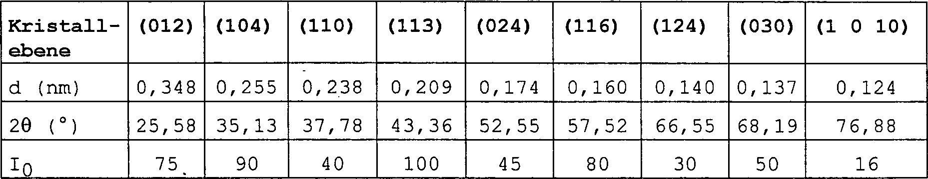
In Tabelle 2 sind der interplanare Abstand d, der 2θ-Wert von TiCN und die Daten für die standardmäßige Röntgenbeugungsintensität I0 von TiC und TiN in jeder Kristallorientierung angegeben. Beim interplanaren Abstand d und beim 2θ-Wert von TiCN handelt es sich um gemessene Werte. Die standardmäßige Röntgenbeugungsintensität I0 von TiC ist aus ASTM File Nr. 29-1361 verfügbar. Der Wert von TiN ist aus ASTM File Nr. 38-1420 verfügbar. Es wird angenommen, dass die standardmäßige Röntgenbeugungsintensität I0 von TiCN identisch mit dem Wert von TiC ist.Table 2 shows the interplanar distance d, the 2θ value of TiCN, and the standard X-ray diffraction intensity data I 0 of TiC and TiN in each crystal orientation. The interplanar distance d and the 2θ value of TiCN are measured values. The standard X-ray diffraction intensity I 0 of TiC is available from ASTM File No. 29-1361. The value of TiN is available from ASTM File No. 38-1420. It is assumed that the standard X-ray diffraction intensity I 0 of TiCN is identical to the value of TiC.
Tabelle
2 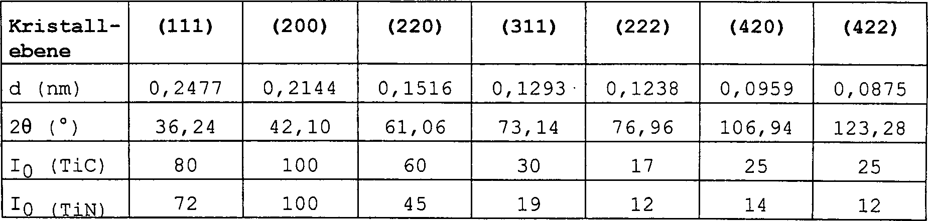
Zur
quantitativen Bewertung der Orientierung von α-Al2O3 von einer (012)-Ebene in eine (1 0 10)-Ebene
wird die vorstehend angegebene Gleichung von TC (hkl) so modifiziert,
dass ein äquivalentes
Röntgenbeugungs-Peakverhältnis PR
(hkl) folgendermaßen
definiert ist:
I (hkl) und I0 (hkl) haben die gleiche Bedeutung wie in der Gleichung (1) von TC (hkl). Die bei der vorstehenden Berechnung verwendeten Kristallorientierungen umfassen eine (1 0 10)-Ebene zusätzlich zu den Ebenen (012) bis (030).I (hkl) and I 0 (hkl) have the same meaning as in equation (1) of TC (hkl). The crystal orientations used in the above calculation include a (1 0 10) plane in addition to the planes (012) to (030).
Wie
aus den Tabellen 1 und 2 klar hervorgeht, beträgt der Unterschied zwischen
dem 2θ-Wert
(76,96°) der
(222)-Ebene von TiCN und dem 2θ-Wert
(76,88°)
der (1 0 10)-Ebene von α-Al2O3 nur 0,08°, so dass
es nicht gelingt, diese beiden Röntgenbeugungspeaks
zu unterscheiden. Somit wurde unter Ausnutzung der Tatsache, dass
die (222)-Ebene strukturell identisch mit einer (111)-Ebene in TiCN
ist, die Röntgenbeugungsintensität der (222)-Ebene
von TiCN aus der nachstehenden Gleichung (3) bestimmt. Der berechnete
Wert für die
Röntgenbeugungsintensität wurde
von der bei etwa 76,9° gemessenen
Röntgenbeugungsintensität I (76,9°) subtrahiert,
um die Röntgenbeugungsintensität von α-Al2O3 in der (1 0 10)-Ebene
zu bestimmen.
Als standardmäßige Röntgenbeugungsintensität I0 (hkl) von TiCN wurde der Wert von TiC verwendet. Würde die standardmäßige Röntgenbeugungsintensität I0 (hkl) von TiN verwendet, so würde I (222) von TiCN I (111) × 12/72 betragen und größer sein als der berechnete Wert der Gleichung (3) und I (1 0 10) von α-Al2O3 wäre kleiner als der berechnete Wert der Gleichung (4). Somit ist klar, dass der Wert von I (1 0 10) von α-Al2O3, der durch die Gleichungen (3) und (4) bestimmt ist, konservativ ist.As the standard X-ray diffraction intensity I 0 (hkl) of TiCN, the value of TiC was used. If the standard X-ray diffraction intensity I 0 (hkl) of TiN were used, I (222) of TiCN would be I (111) × 12/72 and greater than the calculated value of Equation (3) and I (1 0 10) of α-Al 2 O 3 would be smaller than the calculated value of equation (4). Thus, it is clear that the value of I (1 0 10) of α-Al 2 O 3 determined by equations (3) and (4) is conservative.
Als Messergebnis von Mikrophotographien mit einem Rasterelektronenmikroskop (5-2300, Produkt der Fa. Hitachi, Ltd.) wurde festgestellt, dass die durchschnittliche Kristallkorngröße der erfindungsgemäßen, auf α-Aluminiumoxid basierenden Oxidschicht 1 μm oder weniger beträgt, wenn die Dicke der Oxidschicht 2,5 μm oder weniger beträgt 2 μm oder weniger, wenn die Dicke der Oxidschicht mehr als 2,5 μm und 4,5 μm oder weniger beträgt; und 3 μm oder weniger, wenn die Dicke der Oxidschicht mehr als 4,5 μm beträgt. Im übrigen handelt es sich bei der Dicke der α-Aluminiumoxidschicht um einen Mittelwert von Werten für die Dicke, die an einer Vielzahl von Punkten der rasterelektronenmikroskopischen Aufnahmen bestimmt wurden.When Measurement result of microphotographs with a scanning electron microscope (5-2300, product of Hitachi, Ltd.), it was found that the average crystal grain size of the invention, on α-alumina based oxide layer 1 micron or less, when the thickness of the oxide layer is 2.5 μm or less is 2 μm or less, when the thickness of the oxide layer is more than 2.5 μm and 4.5 μm or less; and 3 μm or less if the thickness of the oxide layer is more than 4.5 μm. Otherwise it acts it is the thickness of the α-alumina layer around an average of values for the thickness, at a variety of points of the scanning electron microscopy Recordings were determined.
Die Gründe, warum die erfindungsgemäße, auf Aluminiumoxid basierende Oxidschicht eine derart geringe durchschnittliche Kristallkorngröße aufweist, so dass sich eine hervorragende Beschaffenheit in Bezug auf mechanische Eigenschaften und Schneideeigenschaften der beschichteten Werkzeuge ergibt, sind zwar nicht vollständig klar, es können aber folgende Annahmen gemacht werden:The Reasons, why the invention, on Alumina-based oxide layer such a low average Having crystal grain size, so that is an excellent texture in terms of mechanical Properties and cutting properties of the coated tools are not complete of course, it can but the following assumptions are made:
Gemäß
Wie
in den
Tabelle
3 zeigt die maximalen und minimalen Längen der Diagonalen in den
schraffierten Ebenen in
Wie
in
Wie vorstehend ausgeführt, wird angenommen, dass dann, wenn die α-Al2O3-Schicht einen großen PR-Wert (1 0 10) aufweist und wenn die (1 0 10)-Ebene von α-Al2O3 im wesentlichen parallel zur Substratoberfläche orientiert ist, Kristallkörner mit Wahrscheinlichkeit in vertikaler Richtung zur Substratoberfläche, d. h. in Richtung der Dicke der Aluminiumoxidschicht, verlängert werden, wodurch eine α-Al2O3-Schicht mit im Vergleich zur Oxidschichtdicke kleineren Kristallkorngrößen bereitgestellt wird.As stated above, it is believed that when the α-Al 2 O 3 layer has a large PR value (1 0 10) and when the (1 0 10) plane of α-Al 2 O 3 is substantially oriented parallel to the substrate surface, crystal grains are likely to be elongated in the vertical direction to the substrate surface, ie, in the direction of the thickness of the alumina layer, thereby providing an α-Al 2 O 3 layer with smaller crystal grain sizes compared to the oxide layer thickness.
Tabelle
3 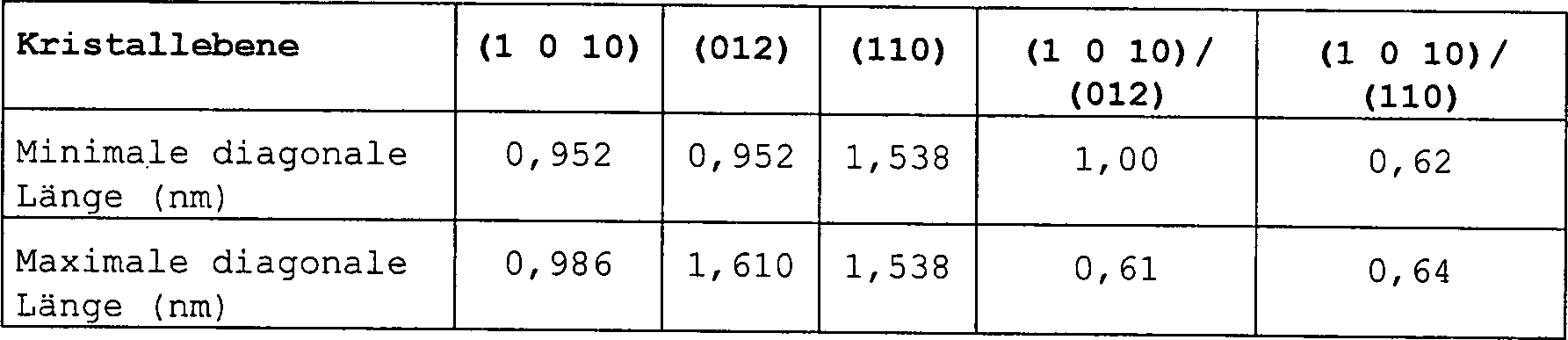
Aus den vorstehenden Gründen ist ersichtlich, dass aufgrund der Tatsache, dass die erfindungsgemäße α-Al2O3-Schicht eine parallel zur Substratoberfläche orientierte (1 0 10)-Ebene aufweist, die α-Aluminiumoxidschicht eine durchschnittliche Kristallkorngröße von 1 μm oder weniger besitzt, wenn die Dicke der Oxidschicht 2,5 μm oder weniger beträgt; 2 μm oder weniger, wenn die Dicke der Oxidschicht mehr als 2,5 μm und 4,5 μm oder weniger beträgt; und 3 μm oder weniger, wenn die Dicke der Oxidschicht mehr als 4,5 μm beträgt. Da die Kristallkorngröße klein ist, ergeben sich auch kleine Werte für die durchschnittliche Oberflächenrauigkeit Ra und die maximale Oberflächenrauigkeit Rmax der α-Aluminiumoxidschicht entlang einer Mittellinie. Bei Verwendung als Schneidewerkzeug ergibt sich somit eine geringe Reibung mit dem der Schneidebearbeitung zu unterziehenden Körper, was zu einem geringeren Abrieb der Überzugsschicht und zu einer geringeren Ablösung von Kristallkörnern aus der Überzugsschicht führt, wodurch sich wiederum bessere mechanische Eigenschaften und eine bessere Dauerhaftigkeit ergeben.From the above reasons, it can be seen that due to the fact that the α-Al 2 O 3 layer of the present invention has a (1 0 10) plane oriented parallel to the substrate surface, the α-alumina layer has an average crystal grain size of 1 μm or less when the thickness of the oxide layer is 2.5 μm or less; 2 μm or less, when the thickness of the oxide layer is more than 2.5 μm and 4.5 μm or less; and 3 μm or less when the thickness of the oxide layer is more than 4.5 μm. Since the crystal grain size is small, small values for the average surface roughness Ra and the maximum surface roughness R max of the α-alumina layer along a center line are also obtained. When used as a cutting tool thus results in a low friction with the cutting process to be subjected body, resulting in less abrasion of the coating layer and less detachment of crystal grains from the coating layer, which in turn result in better mechanical properties and better durability.
Im erfindungsgemäßen beschichteten Werkzeug muss es sich bei der Oxidschicht auf der Basis von α-Aluminiumoxid nicht notwendigerweise um die äußerste Schicht handeln. Es können eine oder mehrere Schichten aus Titanverbindungen, wie TiN, auf der Oxidschicht auf der Basis von α-Aluminiumoxid ausgebildet sein. In diesem Fall wird die durchschnittliche Kristallkorngröße der Oxidschicht auf der Basis von α-Aluminiumoxid nach Entfernen der Schicht aus der Titanverbindung durch chemisches Ätzen unter Verwendung einer wässrigen HF-HNO3-Lösung oder dergl. gemessen.In the coated tool of the present invention, the oxide layer based on α-alumina does not necessarily have to be the outermost layer. One or more layers of titanium compounds such as TiN may be formed on the oxide layer based on α-alumina. In this case, the average crystal grain size of the α-alumina-based oxide film after removing the titanium compound layer by chemical etching using an aqueous HF-HNO 3 solution or the like is measured.
Der erfindungsgemäße, mit α-Aluminiumoxid beschichtete Gegenstand lässt sich unter den nachstehend aufgeführten Bedingungen herstellen. Die erste Überzugsschicht kann auf der Oberfläche eines Substrats ausgebildet werden, indem man mindestens einen der aus der Gruppe Carbide, Nitride, Carbonitride, Oxide, Oxycarbide, Oxynitride und Oxycarbonitride von Metallen der Gruppen IVa, Va und VIa des Periodensystems ausgewählten Bestandteil 5 bis 60 Minuten bei 950 bis 1 020 °C durch ein Filmbildungsverfahren, z. B. chemische Dampfabscheidung (CVD), plasmagestützte chemische Dampfabscheidung (PACVD) und dergl., abscheidet. Um eine hervorragende Haftung an einer α-Aluminiumoxidschicht zu gewährleisten, wird die äußerste Schicht der ersten Überzugsschicht vorzugsweise aus mindestens einem der Oxide, Oxycarbide, Oxynitride und Oxycarbonitride der vorerwähnten Metalle hergestellt. Ein typisches Beispiel für eine derartige äußerste Schicht ist TiCO. Die TiCO-Schicht wird vorzugsweise unter Verwendung eines Reaktionsgasgemisches, das TiCl4-Gas, CH4-Gas, H2-Gas und ein gemischtes Oxidationsgas aus CO2 und CO umfasst, unter den vorstehend beschriebenen Bedingungen gebildet. Das Volumenverhältnis CH4/TiCl4 beträgt vorzugsweise 4–10, das Volumenverhältnis von (CO2 + CO)/TiCl4 vorzugsweise 0,2 bis 10 und das Volumenverhältnis CO/(CO2 + CO) vorzugsweise 0,1–0,98. Es kann angenommen werden, dass das Vorliegen von CO im Reaktionsgasgemisch dazu dient, die Steuerung der Sauerstoffmenge in der gebildeten TiCO-Schicht zu erleichtern, wodurch deren Haftung an der darüber liegenden Oxidschicht auf der Basis von α-Aluminiumoxid verbessert wird.The α-alumina coated article of the present invention can be prepared under the conditions listed below. The first coating layer may be formed on the surface of a substrate by adding at least one of the component selected from the group consisting of carbides, nitrides, carbonitrides, oxides, oxycarbides, oxynitrides and oxycarbonitrides of metals of Groups IVa, Va and VIa of the Periodic Table for 5 to 60 minutes at 950 to 1020 ° C by a film-forming method, e.g. As chemical vapor deposition (CVD), plasma-enhanced chemical vapor deposition (PACVD) and the like., Deposits. In order to ensure excellent adhesion to an α-alumina layer, the outermost layer of the first coating layer is preferably prepared from at least one of the oxides, oxycarbides, oxynitrides and oxycarbonitrides of the aforementioned metals. A typical example of such an outermost layer is TiCO. The TiCO layer is preferably formed using a reaction gas mixture comprising TiCl 4 gas, CH 4 gas, H 2 gas, and a mixed oxidizing gas of CO 2 and CO, under the conditions described above. The volume ratio CH 4 / TiCl 4 is preferably 4-10, the volume ratio of (CO 2 + CO) / TiCl 4 is preferably 0.2 to 10 and the volume ratio CO / (CO 2 + CO) is preferably 0.1-0.98 , It can be assumed that the presence of CO in the reaction gas mixture serves to facilitate the control of the amount of oxygen in the TiCO layer formed, thereby improving its adhesion to the overlying α-alumina based oxide layer.
Die zweite Überzugsschicht, die eine Oxidschicht auf der Basis von α-Aluminiumoxid umfasst, wird auf der vorstehenden äußersten Schicht der ersten Überzugsschicht abgeschieden, wozu man ein Reaktionsgasgemisch mit einem Gehalt an AlCl3-Gas und einem Sauerstoffatome enthaltenden Mischgas, das aus CO2 und CO besteht, neben H2 als Trägergas verwendet. Das Volumenverhältnis (CO2 + CO) zum AlCl3-Gas beträgt vorzugsweise 2–15. Das Volumenverhältnis CO zu (CO2 + CO) beträgt vorzugsweise 0,5 bis 0,95 und insbesondere 0,6 bis 0,9. Wenn das Volumenverhältnis von CO zu (CO2 + CO) weniger als 0,5 beträgt, so besteht eine Tendenz, dass die Aluminiumoxidschicht sich in der (110)-Ebene orientiert. Wenn andererseits das Volumenverhältnis von CO zu (CO2 + CO) mehr als 0,95 beträgt, so nimmt die Abscheidungsgeschwindigkeit von Al2O3 rasch ab, was zu einem schlechten Wirkungsgrad bei der Bildung der Oxidschicht auf der Basis von α-Aluminiumoxid führt. Bei Verwendung der vorstehenden Reaktionsgaszusammensetzung weist die erhaltene Oxidschicht auf der Basis von α-Aluminiumoxid eine (1 0 10)-Orientierung und eine ausreichend geringe durchschnittliche Kristallkorngröße auf.The second coating layer comprising an α-alumina-based oxide layer is deposited on the above outermost layer of the first coating layer, to which a reaction gas mixture containing AlCl 3 gas and a mixed gas containing oxygen atoms composed of CO 2 and CO, in addition to H 2 used as a carrier gas. The volume ratio (CO 2 + CO) to AlCl 3 gas is preferably 2-15. The volume ratio CO to (CO 2 + CO) is preferably 0.5 to 0.95 and in particular 0.6 to 0.9. When the volume ratio of CO to (CO 2 + CO) is less than 0.5, there is a tendency for the aluminum oxide layer to orient in the (110) plane. On the other hand, when the volume ratio of CO to (CO 2 + CO) is more than 0.95, the deposition rate of Al 2 O 3 rapidly decreases, resulting in poor efficiency in forming the α-alumina-based oxide film , When using the above reaction gas composition, the resulting α-alumina-based oxide layer has (10O) orientation and sufficiently small average crystal grain size.
Das Verfahren der chemischen Dampfabscheidung und der plasmagestützten chemischen Dampfabscheidung kann zur Bildung der Oxidschicht auf der Basis von α-Aluminiumoxid herangezogen werden.The Process of chemical vapor deposition and plasma-based chemical Vapor deposition can be based on the formation of the oxide layer of α-alumina be used.
Die Gegenstände, auf denen die erfindungsgemäßen einlagigen oder mehrlagigen Überzüge gebildet werden, sind nicht auf Werkzeuge zur Schneidebearbeitung beschränkt, sondern es kann sich auch um Gegenstände, wie verschiedene abriebbeständige Körper, Formgebungswerkzeuge, Druckgussstifte, Elemente, die mit Metallschmelzen in Kontakt kommen, und dergl., handeln.The objects on which the single layer according to the invention or multilayer coatings are formed, are not limited to cutting tools, but it can also be objects, like different abrasion resistant Body, Shaping tools, die-cast pins, elements with molten metal come in contact, and the like, act.
Das Aluminiumoxid ist nicht nur auf α-Aluminiumoxid beschränkt, es kann sich auch um ein Gemisch aus α-Aluminiumoxid mit anderen Aluminiumoxiden, wie ĸ-Aluminiumoxid, γ-Aluminiumoxid, θ-Aluminiumoxid, δ-Aluminiumoxid, χ-Aluminiumoxid und dergl., oder um ein Gemisch aus α-Aluminiumoxid mit anderen Oxiden, wie Zirkoniumoxid und dergl., handeln, sofern es sich bei der Hauptkomponente der Aluminiumoxidschicht um α-Aluminiumoxid handelt. Somit bedeutet der hier verwendete Ausdruck "Oxidschicht auf der Basis von α-Aluminiumoxid" eine Oxidschicht auf der Basis von α-Aluminiumoxid, bei der 60 % oder mehr der gesamten Röntgenbeugungspeaks sich von α-Aluminiumoxid ableiten.The Alumina is not limited to α-alumina limited, it may also be a mixture of α-alumina with other aluminum oxides, such as ĸ-alumina, γ-alumina, θ-alumina, δ-alumina, χ-alumina and the like, or a mixture of α-alumina with other oxides, such as Zirconia and the like, unless the main component the alumina layer is alpha alumina. Thus, as used herein, the term "alpha-alumina based oxide layer" means an oxide layer based on α-alumina, at the 60% or more of the total X-ray diffraction peaks of α-alumina derived.
Nachstehend wird die vorliegende Erfindung unter Bezugnahme auf Beispiele erläutert, die jedoch den Schutzumfang der Erfindung nicht beschränken sollen.below For example, the present invention will be explained with reference to Examples which however, it is not intended to limit the scope of the invention.
Beispiel 1example 1
Ein zementiertes Carbidsubstrat für ein Schneidewerkzeug mit einer Zusammensetzung aus 72 Gew.-% WC, 8 Gew.-% TiC, 11 Gew.-% (Ta, Nb) C und 9 Gew.-% Co wurde in einen CVD-Ofen eingesetzt, um das zementierte Carbidsubstrat durch chemische Dampfabscheidung bei 900 °C unter Verwendung von TiCl4-Gas, N2-Gas und H2-Trägergas mit einer TiN-Schicht mit einer Dicke von 0,3 μm und sodann bei 900 °C unter Verwendung von H2-Trägergas, TiCl4-Gas und CH3CN-Gas mit einer 6 μm dicken TiCN-Schicht zu überziehen. Ferner wurde eine TiC-Schicht mit einer Dicke von etwa 0,05-2 μm auf der TiCN-Schicht durch Zufuhr von H2-Trägergas, TiCl4-Gas und CH4-Gas zum CVD-Ofen bei 950–1 200 °C mit einer Strömungsgeschwindigkeit von 2 200 ml/min bei einer Zufuhrzeit von 5–120 Minuten gebildet. Anschließend wurde eine TiCO-Schicht 5–30 Minuten unter Verwendung des vorstehenden Reaktionsgasstroms, dem ein Mischgas aus CO2 und CO mit 2,2-110 ml/min zugesetzt wurde, in einer Dicke von 0,05–0,5 μm gebildet.A cemented carbide substrate for a cutting tool having a composition of 72 wt% WC, 8 wt% TiC, 11 wt% (Ta, Nb) C and 9 wt% Co was placed in a CVD furnace, around the cemented carbide substrate by chemical vapor deposition at 900 ° C using TiCl 4 gas, N 2 gas and H 2 carrier gas with a TiN layer having a thickness of 0.3 μm and then at 900 ° C using Cover H 2 carrier gas, TiCl 4 gas and CH 3 CN gas with a 6 μm thick TiCN layer. Further, a TiC layer having a thickness of about 0.05-2 μm was formed on the TiCN layer by supplying H 2 carrier gas, TiCl 4 gas and CH 4 gas to the CVD furnace at 950-1,200 ° C formed at a flow rate of 2 200 ml / min at a feed time of 5-120 minutes. Subsequently, a TiCO layer was formed in a thickness of 0.05-0.5 μm for 5-30 minutes using the above reaction gas stream to which a mixed gas of CO 2 and CO at 2.2-110 ml / min was added.
Man ließ 310 ml/min H2-Gas und 130 ml/min HCl-Gas durch ein kleines Rohr, das mit Aluminiumstücken gefüllt war, bei 350 °C strömen, um ein AlCl3-Gas zu erzeugen, das dem CVD-Ofen zusammen mit 2 Liter/min H2-Gas, 50 ml/min CO2-Gas und 350 ml/min CO-Gas zugeführt wurde, um bei 1 000-1 050 °C eine Aluminiumoxidschicht auf der TiCO-Schicht zu bilden.310 ml / min of H 2 gas and 130 ml / min of HCl gas were flowed through a small tube filled with pieces of aluminum at 350 ° C to produce an AlCl 3 gas, which coextensive with the CVD furnace with 2 liters / min of H 2 gas, 50 ml / min of CO 2 gas and 350 ml / min of CO gas was added to form at 1000-1 050 ° C an aluminum oxide layer on the TiCO layer.
Die Röntgenbeugung des erhaltenen mehrlagigen Überzugs wurde durch das 2θ-θ-Verfahren bei 2θ von 10°–90° unter Verwendung eines Röntgenbeugungsanalysators (RU-300R, Produkt der Fa. Rigaku Denki K. K.) gemessen. Als Röntgenstrahlenquelle wurde nur der Kα1-Strahl von Cu (Wellenlänge λ = 0,154 nm) verwendet. Der Kα2-Strahl und Rauschstrahlen wurden beseitigt.The X-ray diffraction of the obtained multilayer coating was determined by the 2θ-θ method at 2θ of 10 ° -90 ° using an X-ray diffraction analyzer (RU-300R, product of Rigaku Denki K.K.). As an X-ray source became only the Kα1 beam of Cu (wavelength λ = 0.154 nm). The Kα2 beam and noise rays have been eliminated.
In den Tabellen 4–6 bedeutet α (hkl) den (hkl)-Wert von α-Al2O3. Aus den Tabellen 4 bis 6 geht klar hervor, dass der PR-Wert (1 0 10) von α-Al2O3 in jeder Probe 1,3 oder mehr und vorzugsweise 1,5 oder mehr beträgt. Ferner geht hervor, dass der maximale Wert unter den PR-Werten (hkl) lag und somit die durchschnittliche Kristallkorngröße 1 μm oder weniger betrug, wenn die Dicke der Oxidschicht 2,5 μm oder weniger betrug; 2 μm oder weniger, wenn die Dicke der Oxidschicht mehr als 2,5 μm und 4,5 μm oder weniger betrug; und 3 μm oder weniger, wenn die Dicke der Oxidschicht mehr als 4,5 μm betrug.In Tables 4-6, α (hkl) represents the (hkl) value of α-Al 2 O 3 . It is clear from Tables 4 to 6 that the PR value (1 0 10) of α-Al 2 O 3 in each sample is 1.3 or more, and preferably 1.5 or more. Further, it is understood that the maximum value was below the PR values (hkl), and thus the average crystal grain size was 1 μm or less when the thickness of the oxide layer was 2.5 μm or less; 2 μm or less, when the thickness of the oxide layer was more than 2.5 μm and 4.5 μm or less; and 3 μm or less when the thickness of the oxide layer was more than 4.5 μm.
Das
Verfahren zum Messen der durchschnittlichen Kristallkorngröße wird
nachstehend unter Verwendung der Probe Nr. 14 erläutert.
Im
Fall von
Eine polierte Oberfläche der einzelnen Proben wurde bei einem Neigungswinkel von 10° mit einem Lasermikroskop betrachtet, um die Abstände zwischen benachbarten Schichtgrenzen zu messen und dadurch die Dicke der einzelnen Schichten zu bestimmen.A polished surface The individual samples were at an inclination angle of 10 ° with a Laser microscope considered the distances between adjacent layer boundaries to measure and thereby determine the thickness of the individual layers.
Beim
kontinuierlichen Schneidetest von Gusseisen wurden Schneidewerkzeuge
(5 Werkzeuge für jede
der Proben Nr. 11-16), die gemäß Beispiel
1 hergestellt worden waren, 1 Stunde unter den nachstehend angegebenen
Bedingungen eingesetzt. Anschließend wurde der Abrieb einer
Flanke eines jeden Werkzeugs mit einem optischen Mikroskop (Vergrößerung
- Zu schneidender Körper: Gusseisen FC25 (HB230),Body to be cut: Cast iron FC25 (HB230),
- Werkzeugform: CNMA 120412,Tool shape: CNMA 120412,
- Schneidegeschwindigkeit: 300 m/min,Cutting speed: 300 m / min,
- Zufuhrgeschwindigkeit: 0,3 mm/Umdrehung,Feed rate: 0.3 mm / rev,
- Schneidetiefe: 2,0 mm undCutting depth: 2.0 mm and
- Schneideflüssigkeit: Wässrige Lösung.Cutting fluid: aqueous Solution.
Anschließend wurden beim intermittierenden Schneidetest Schneidewerkzeuge (jeweils 5 für die Proben Nr. 11 bis 16) auf die vorstehende Weise unter den folgenden Bedingungen eingesetzt, bis es zur Splitterbildung kam. Die maximale Anzahl an intermittierenden Schneidevorgängen wurde ermittelt. Die Splitterbildung der einzelnen beschichteten Werkzeuge wurde mit einem optischen Mikroskop betrachtet (Vergrößerung 50).Subsequently were Intermittent cutting test Cutting tools (each 5 for the Sample Nos. 11 to 16) in the above manner under the following Conditions used until it came to splintering. The maximal Number of intermittent cutting operations was determined. The splinter formation The individual coated tools was made with an optical Microscope considered (magnification 50).
- Zu schneidender Körper: Gerillter Körper aus S53C (HS38),Body to be cut: Grooved body from S53C (HS38),
- Schneidegeschwindigkeit: 220 m/min,Cutting speed: 220 m / min,
- Zufuhrgeschwindigkeit: 0,2 mm/Umdrehung,Feed rate: 0.2 mm / rev,
- Schneidetiefe: 2,0 mm undCutting depth: 2.0 mm and
- Schneideflüssigkeit: Keine (trockenes Schneiden).Cutting fluid: None (dry cutting).
Die Ergebnisse des Schneidetests sind in Tabelle 6 aufgeführt. Aus Tabelle 6 ist klar ersichtlich, dass dann, wenn der PR (1 0 10)-Wert 1,3 oder mehr beträgt (Probe Nr. 12) die durchschnittliche Kristallkorngröße den geringen Wert von 1,8 μm bei einer Dicke der Aluminiumoxidschicht von 3,5 μm aufwies, was gute Schneideeigenschaften ergab (maximale kontinuierliche Schneidezeit = 60 Minuten und maximale Anzahl der intermittierenden Schneidevorgänge = 1 000). Auch bei einem PR (1 0 10)-Wert von 1,5 oder mehr (Probe Nr. 13) ergab sich eine durchschnittliche Kristallkorngröße von nur 1,3 μm bei einer Schichtdicke von 3,5 μm, was zu besseren Schneideeigenschaften führte (maximale kontinuierliche Schneidezeit = 80 Minuten und maximale Anzahl der intermittierenden Schneidevorgänge = 1 300). Bei einem PR (1 0 10)-Wert von 3,76 (Probe Nr. 14) ergab sich ein geringer Wert für die durchschnittliche Kristallkorngröße von 0,7 μm bei einer Schichtdicke von 3,5 μm, was zu wesentlich besseren Schneideeigenschaften führte (maximale kontinuierliche Schneidezeit = 90 Minuten und maximale Anzahl der intermittierenden Schneidevorgänge = 1 500).The Results of the cutting test are shown in Table 6. Out Table 6 clearly shows that when the PR (1 0 10) value Is 1.3 or more (Sample No. 12) the average crystal grain size is the small one Value of 1.8 μm with a thickness of the aluminum oxide layer of 3.5 microns, which gave good cutting properties (maximum continuous cutting time = 60 minutes and maximum number of intermittent cutting operations = 1 000). Also with a PR (1 0 10) value of 1.5 or more (Sample No. 13) resulted in an average Crystal grain size of only 1.3 μm at a layer thickness of 3.5 μm, which led to better cutting properties (maximum continuous Cutting time = 80 minutes and maximum number of intermittent cutting operations = 1,300). At a PR (1 0 10) value of 3.76 (Sample No. 14) a low value for the average crystal grain size of 0.7 microns at a layer thickness of 3.5 microns, resulting in resulted in significantly better cutting properties (maximum continuous Cutting time = 90 minutes and maximum number of intermittent cutting operations = 1,500).
Aus den Ergebnissen der Schneidetests der vorstehenden Proben und der Proben Nr. 11, 15 und 16 ist klar ersichtlich, dass der PR (1 0 10)-Wert im erfindungsgemäß beschichteten Werkzeug 1,3 oder mehr beträgt; dass die durchschnittliche Kristallkorngröße 1 μm oder weniger bei einer Dicke der Oxidschicht von 2,5 μm oder weniger; 2 μm oder weniger bei einer Dicke der Oxidschicht von mehr als 2,5 μm und 4,5 μm oder weniger; und 1,7 μm oder weniger bei einer Dicke der Oxidschicht von mehr als 4,5 μm und 6 μm oder weniger beträgt; dass die maximale kontinuierliche Schneidezeit 60 oder mehr beträgt; und dass die maximale Anzahl der intermittierenden Schneidevorgänge 1 000 oder mehr beträgt.From the results of the cutting tests of the above samples and samples Nos. 11, 15 and 16, it can be clearly seen that the PR (10 0) value in the coated tool according to the present invention is 1.3 or more; the average crystal grain size is 1 μm or less with an oxide layer thickness of 2.5 μm or less; 2 μm or less at a thickness of the oxide layer of more than 2.5 μm and 4.5 μm or less; and 1.7 μm or less at a thickness of the oxide layer of more than 4.5 μm and 6 μm or less; that the maximum continuous cutting time is 60 or more; and that the maximum number of intermittent cutting operations is 1,000 or more.
Vergleichsbeispiel 1Comparative Example 1
Um den Einfluss des PR (1 0 10)-Werts auf die durchschnittliche Kristallkorngröße der Oxidschicht auf der Basis von α-Aluminiumoxid und auf die Schneideeigenschaften des beschichteten Werkzeugs zu untersuchen, wurde ein zementiertes Carbidsubstrat für ein Schneidewerkzeug mit einer Zusammensetzung aus 72 Gew.-% WC, 8 Gew.-% TiC, 11 Gew.-% (Ta,Nb) C und 9 Gew.-% Co mit einer TiN-Schicht mit einer Dicke von 0,3 μm und einer TiCN-Schicht mit einer Dicke von 6 μm beschichtet. Ferner wurde eine TiC-Schicht mit einer Dicke von etwa 0,05-2 μm auf der TiCN-Schicht innerhalb von 5 bis 120 Minuten bei 1 010 °C unter Verwendung von H2-Trägergas, TiCl4-Gas und CH4-Gas gebildet. Nach Beendigung der Zufuhr von TiCl4-Gas und CH4-Gas wurde H2-Trägergas und CO2-Gas zugeführt, um die TiC-Schicht 15 Minuten bei 1 010 °C zu oxidieren. Anschließend wurden H2-Gas, AlCl3-Gas und CO2-Gas bei 1 020 °C zugeführt, um auf der oxidierten TiC-Schicht (Titanoxide, wie Ti2O3, Ti3O5, TiO2 und dergl.) unter den gleichen Bedingungen wie in Beispiel 1 eine Aluminiumoxidschicht zu bilden.To investigate the influence of the PR (1 0 10) value on the average crystal grain size of the α-alumina oxide layer and on the cutting properties of the coated tool, a cemented carbide substrate for a cutting tool having a composition of 72% by weight was used. % WC, 8 wt% TiC, 11 wt% (Ta, Nb) C and 9 wt% Co with a TiN layer having a thickness of 0.3 μm and a TiCN layer having a thickness of 6 μm coated. Further, a TiC layer having a thickness of about 0.05-2 μm was formed on the TiCN layer within 5 to 120 minutes at 1010 ° C using H 2 carrier gas, TiCl 4 gas and CH 4 gas educated. After completion of the supply of TiCl 4 gas and CH 4 gas, H 2 carrier gas and CO 2 gas were supplied to oxidize the TiC layer at 1 010 ° C for 15 minutes. Subsequently, H 2 gas, AlCl 3 gas and CO 2 gas were supplied at 1020 ° C to deposit on the oxidized TiC layer (titanium oxides such as Ti 2 O 3 , Ti 3 O 5 , TiO 2 and the like). under the same conditions as in Example 1 to form an aluminum oxide layer.
Das erhaltene beschichtete Werkzeug wurde einer Messung seiner Röntgenbeugungsintensität, des äquivalenten Röntgenbeugungs-Peakverhältnisses PR (1 0 10) und der durchschnittlichen Kristallkorngröße unterzogen. Die Ergebnisse sind in den Tabellen 4 bis 6 aufgeführt. Aus Tabelle 6 ist klar ersichtlich, dass das Schneidewerkzeug von Vergleichsbeispiel 1 einen PR (1 0 10)-Wert von weniger als 1,3 und eine hohe durchschnittliche Kristallkorngröße von 2,7 μm bei einer Dicke der Aluminiumoxidschicht von 3,5 μm aufwies.The The coated tool obtained was subjected to measurement of its X-ray diffraction intensity, the equivalent X-ray diffraction peak ratio Subjected to PR (1 0 10) and the average crystal grain size. The results are shown in Tables 4 to 6. Out Table 6 clearly shows that the cutting tool of Comparative Example 1 a PR (1 0 10) value of less than 1.3 and a high average Crystal grain size of 2.7 microns at a Thickness of the aluminum oxide layer of 3.5 microns had.
Als Ergebnis der wie in Beispiel 1 unter Verwendung von 5 Schneidewerkzeugen gemäß dem Vergleichsbeispiel 1 durchgeführten Schneidetests wurde festgestellt, dass sich die Oxidschicht nach einem 30-minütigen kontinuierlichen Schneidevorgang ablöste und dass nach 800 intermittierenden Schneidevorgängen unter Stoßwirkung eine starke Splitterbildung erfolgte, was für die schlechten Eigenschaften der Schneidewerkzeuge von Vergleichsbeispiel 1 spricht.When Result as in Example 1 using 5 cutting tools according to the comparative example 1 performed Cutting tests were found that the oxide layer after a 30-minute drive continuous cutting process replaced and that after 800 intermittent cutting operations under impact A strong fragmentation took place, what for the bad qualities the cutting tools of Comparative Example 1 speaks.
Tabelle
4 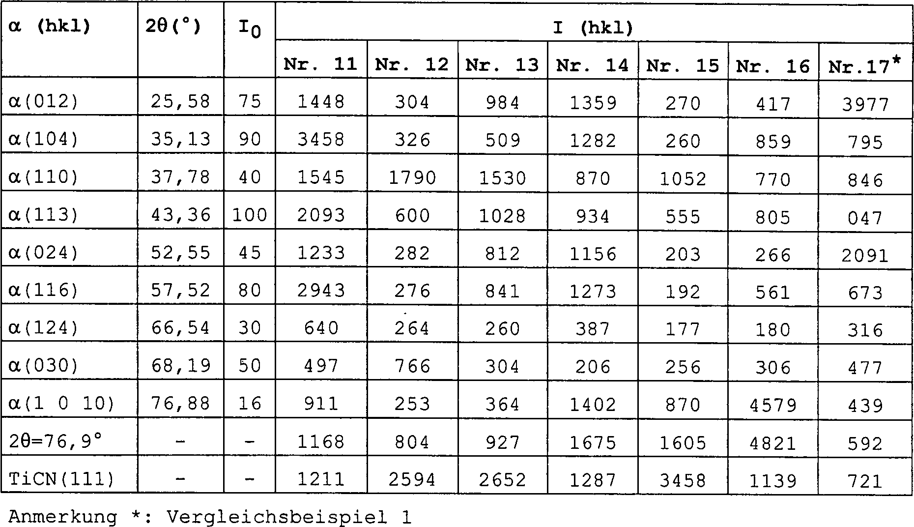
Tabelle
5 
Tabelle
6 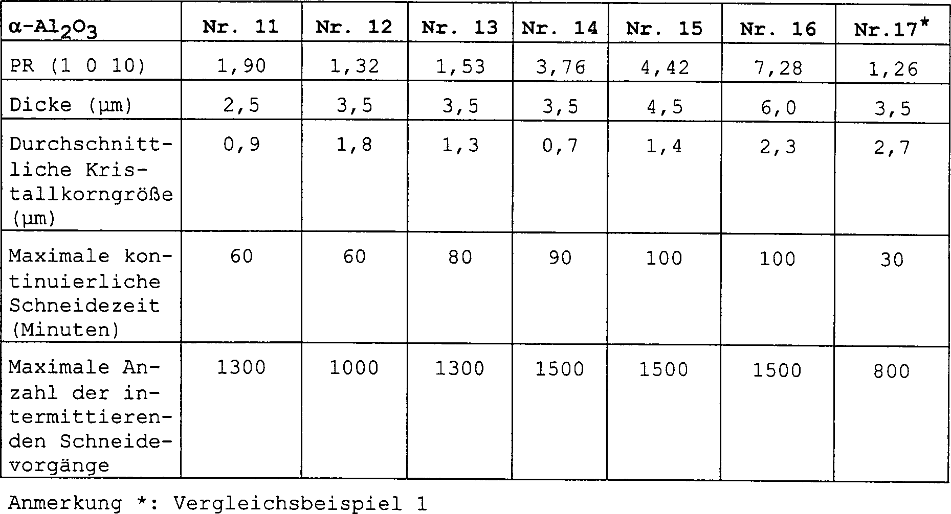
Beispiel 2Example 2
Nach Durchführung des gleichen Verfahrens wie in Beispiel 1 bis zur Bildung einer Aluminiumoxidschicht wurden 4 Liter/min H2-Trägergas, 50 ml/min TiCl4-Gas und 1,3 Liter/min N2-Gas 20 Minuten zur Bildung einer Titannitridschicht auf der Aluminiumoxidschicht bei 1 020 °C zugeführt. Die erhaltenen beschichteten Werkzeuge wurden einer Messung ihrer Röntgenbeugungsintensität, des äquivalenten Röntgenbeugungs-Peakverhältnisses PR (hkl), des PR (1 0 10)-Werts, der Schichtdicken, der durchschnittlichen Kristallkorngröße und der Schneideeigenschaften (maximale kontinuierliche Schneidezeit und maximale Anzahl an intermittierenden Schneidevorgängen) unterworfen. Die Messergebnisse für diese Eigenschaften sind in den Tabellen 7 bis 9 aufgeführt.After carrying out the same procedure as in Example 1 to form an alumina layer, 4 liters / min of H 2 carrier gas, 50 ml / min of TiCl 4 gas and 1.3 liters / min of N 2 gas were added for 20 minutes to form a titanium nitride layer the alumina layer fed at 1 020 ° C. The obtained coated tools were subjected to measurement of their X-ray diffraction intensity, equivalent X-ray diffraction peak ratio PR (hkl), PR (10 0) value, layer thicknesses, average crystal grain size and cutting properties (maximum continuous cutting time and maximum number of intermittent cutting operations). subjected. The measurement results for these properties are listed in Tables 7 to 9.
Aus Tabelle 9 ist klar ersichtlich, dass die α-Al2O3-Schicht von Beispiel 2 einen PR (1 0 10)-Wert von 1,3 oder mehr und insbesondere von 1,5 oder mehr aufwies und das Maximum unter den PR (hkl)-Werten zeigte und dass die durchschnittliche Kristallkorngröße 1 μm oder weniger bei einer Dicke der Aluminiumoxidschicht von 2,5 μm oder weniger; 2 μm oder weniger bei einer Dicke der Aluminiumoxidschicht von mehr als 2,5 μm und 4,5 μm oder weniger; und 3 μm oder weniger bei einer Dicke der Aluminiumoxidschicht von mehr als 4,5 μm betrug.It is clearly seen from Table 9 that the α-Al 2 O 3 layer of Example 2 had a PR (1 0 10) value of 1.3 or more, and more preferably 1.5 or more, and the maximum under PR (hkl) values, and that the average crystal grain size is 1 μm or less at a thickness of the aluminum oxide layer of 2.5 μm or less; 2 μm or less at a thickness of the aluminum oxide layer of more than 2.5 μm and 4.5 μm or less; and 3 μm or less at a thickness of the aluminum oxide layer of more than 4.5 μm.
Aus Tabelle 9 wurde ferner festgestellt, dass bei einem PR (1 0 10)-Wert von 1,3 oder mehr (Probe Nr. 24), die durchschnittliche Kristallkorngröße nur 3,0 μm bei einer Dicke der Aluminiumoxidschicht von 6 μm betrug, was bessere Schneideeigenschaften ergibt (maximale kontinuierliche Schneidezeit = 130 Minuten und maximale Anzahl der intermittierenden Schneidevorgänge = 1 800). Wenn ferner der PR (1 0 10)-Wert 1,5 oder mehr betrug (Probe Nr. 25), ergab sich eine durchschnittliche Kristallkorngröße von nur 2,5 μm bei einer Dicke der Aluminiumoxidschicht von 6 μm, was wesentlich bessere Schneideeigenschaften bedeutete (maximale kontinuierliche Schneidezeit = 150 Minuten und maximale Anzahl der intermittierenden Schneidevorgänge = 2 000). Aus diesen Daten wurde bestätigt, dass der PR (1 0 10)-Wert vorzugsweise 1,5 oder mehr beträgt und dass die durchschnittliche Kristallkorngröße vorzugsweise 2,5 μm oder weniger beträgt, wenn die Dicke der Oxidschicht 6,0 μm übersteigt.Out Table 9 was further found to have a PR (1 0 10) value of 1.3 or more (Sample No. 24), the average crystal grain size is only 3.0 μm at one Thickness of the aluminum oxide layer of 6 microns, giving better cutting properties results (maximum continuous cutting time = 130 minutes and maximum Number of intermittent cutting operations = 1 800). Furthermore, if the PR (1 0 10) value Was 1.5 or more (Sample No. 25), the average was Crystal grain size of only 2.5 μm at a thickness of the aluminum oxide layer of 6 microns, which significantly improved cutting properties meant (maximum continuous cutting time = 150 minutes and maximum number of intermittent cutting operations = 2 000). From these data, it was confirmed that the PR (1 0 10) value preferably 1.5 or more and that the average crystal grain size is preferably 2.5 μm or less is, when the thickness of the oxide layer exceeds 6.0 μm.
Die Probe Nr. 22 zeigte einen PR (1 0 10)-Wert von 1,71 und eine durchschnittliche Kristallkorngröße von 2,0 μm bei einer Dicke der Aluminiumoxidschicht von 4,5 μm, was hervorragende Schneideeigenschaften bedeutet (maximale kontinuierliche Schneidezeit = 100 Minuten und maximale Anzahl der intermittierenden Schneidevorgänge = 1 500). Ferner zeigte die Probe Nr. 23 einen PR (1 0 10)-Wert von 3,69 und eine durchschnittliche Kristallkorngröße von nur 1,5 μm bei einer Dicke der Aluminiumoxidschicht von 4,5 μm, was ausgezeichnete Schneideeigenschaften bedeutete (maximale kontinuierliche Schneidezeit = 130 Minuten und maximale Anzahl der intermittierenden Schneidevorgänge = 1 800). Es wurde bestätigt, dass die durchschnittliche Kristallkorngröße vorzugsweise 1,5 μm oder weniger bei einer Schichtdicke von 4,5 μm beträgt.The Sample No. 22 showed a PR (10 0) value of 1.71 and an average Crystal grain size of 2.0 microns at a Alumina layer thickness of 4.5 μm, which means excellent cutting properties (maximum continuous cutting time = 100 minutes and maximum Number of intermittent cutting operations = 1 500). Further showed Sample No. 23 has a PR (1 0 10) value of 3.69 and an average Crystal grain size of only 1.5 μm at a thickness of the aluminum oxide layer of 4.5 microns, which excellent cutting properties meant (maximum continuous cutting time = 130 minutes and maximum Number of intermittent cutting operations = 1 800). It was confirmed that the average crystal grain size is preferably 1.5 μm or less at a layer thickness of 4.5 microns is.
Vergleichsbeispiel 2Comparative Example 2
Zur Untersuchung des Einflusses des PR (1 0 10)-Werts auf die durchschnittliche Kristallkorngröße der Oxidschicht auf der Basis von α-Aluminiumoxid und auf die Schneideeigenschaften des beschichteten Werkzeugs wurde das Beispiel 2 bis zur Bildung der TiC-Schicht wiederholt. Anschließend wurden nach Abbrechen der Zufuhr von TiCl4-Gas und CH4-Gas ein H2-Trägergas und ein CO2-Gas 15 Minuten bei 1 010 °C zugeführt, um die TiC-Schicht zu oxidieren. Sodann wurden H2-Gas, A1C13-Gas und CO2-Gas bei 1 020 °C zugeführt, um auf der Schicht von oxidiertem TiC (Titanoxid) unter den gleichen Bedingungen wie in Beispiel 2 eine Aluminiumoxidschicht zu bilden. Ferner wurden 4 Liter/min H2-Gas, 50 ml/min TiCl4-Gas und 1,3 Liter/min N2-Gas 20 Minuten bei 1 020 °C zugeführt, um auf der Aluminiumoxidschicht eine Titannitridschicht zu bilden.In order to investigate the influence of the PR (10 0) value on the average crystal grain size of the α-alumina-based oxide layer and the cutting properties of the coated tool, Example 2 was repeated until the formation of the TiC layer. Then, after stopping the supply of TiCl 4 gas and CH 4 gas, an H 2 carrier gas and a CO 2 gas were supplied at 1 010 ° C for 15 minutes to oxidize the TiC layer. Then, H 2 gas, AlCl 3 gas and CO 2 gas were supplied at 1020 ° C to form an alumina layer on the oxidized TiC (titanium oxide) layer under the same conditions as in Example 2. Further, 4 liters / min of H2 gas, 50 ml / min of TiCl 4 gas and 1.3 liters / min of N 2 gas were supplied at 1020 ° C for 20 minutes to form a titanium nitride layer on the alumina layer.
Das erhaltene beschichtete Werkzeug wurde einer Messung seines äquivalenten Röntgenbeugungs-Peakverhältnisses PR (1 0 10), der Schichtdicke und der durchschnittlichen Kristallkorngröße unterzogen. Die Ergebnisse sind in Tabelle 9 aufgeführt. Aus Tabelle 9 ist klar ersichtlich, dass das Schneidewerkzeug von Vergleichsbeispiel 2 einen PR (1 0 10)-Wert von weniger als 1,3 und eine hohe durchschnittliche Kristallkorngröße von 3,5 μm bei einer Dicke der Aluminiumoxidschicht von 6 μm aufwies.The The coated tool obtained was a measurement of its equivalent X-ray diffraction peak ratio PR (1 0 10), the layer thickness and the average crystal grain size subjected. The results are shown in Table 9. From Table 9 is clear It can be seen that the cutting tool of Comparative Example 2 a PR (1 0 10) value of less than 1.3 and a high average Crystal grain size of 3.5 microns at a Thickness of the aluminum oxide layer of 6 microns had.
Als Ergebnis der gleichen Schneidetests wie in Beispiel 2 unter Verwendung von 5 Schneidewerkzeugen gemäß Vergleichsbeispiel 2 wurde festgestellt, dass sich die Oxidschicht nach einem 40-minütigen kontinuierlichen Schneidebetrieb ablöste und dass nach 600 intermittierenden Schneidevorgängen unter Stoßeinwirkung eine starke Splitterbildung auftrat, was für die schlechten Eigenschaften der Schneidewerkzeuge von Vergleichsbeispiel 2 spricht.When Result of the same cutting tests as in Example 2 using of 5 cutting tools according to the comparative example 2, it was found that the oxide layer after a 40-minute continuous Cutting operation replaced and that after 600 intermittent cutting operations under impact a strong fragmentation occurred, what for the bad qualities the cutting tools of Comparative Example 2 speaks.
Tabelle
7 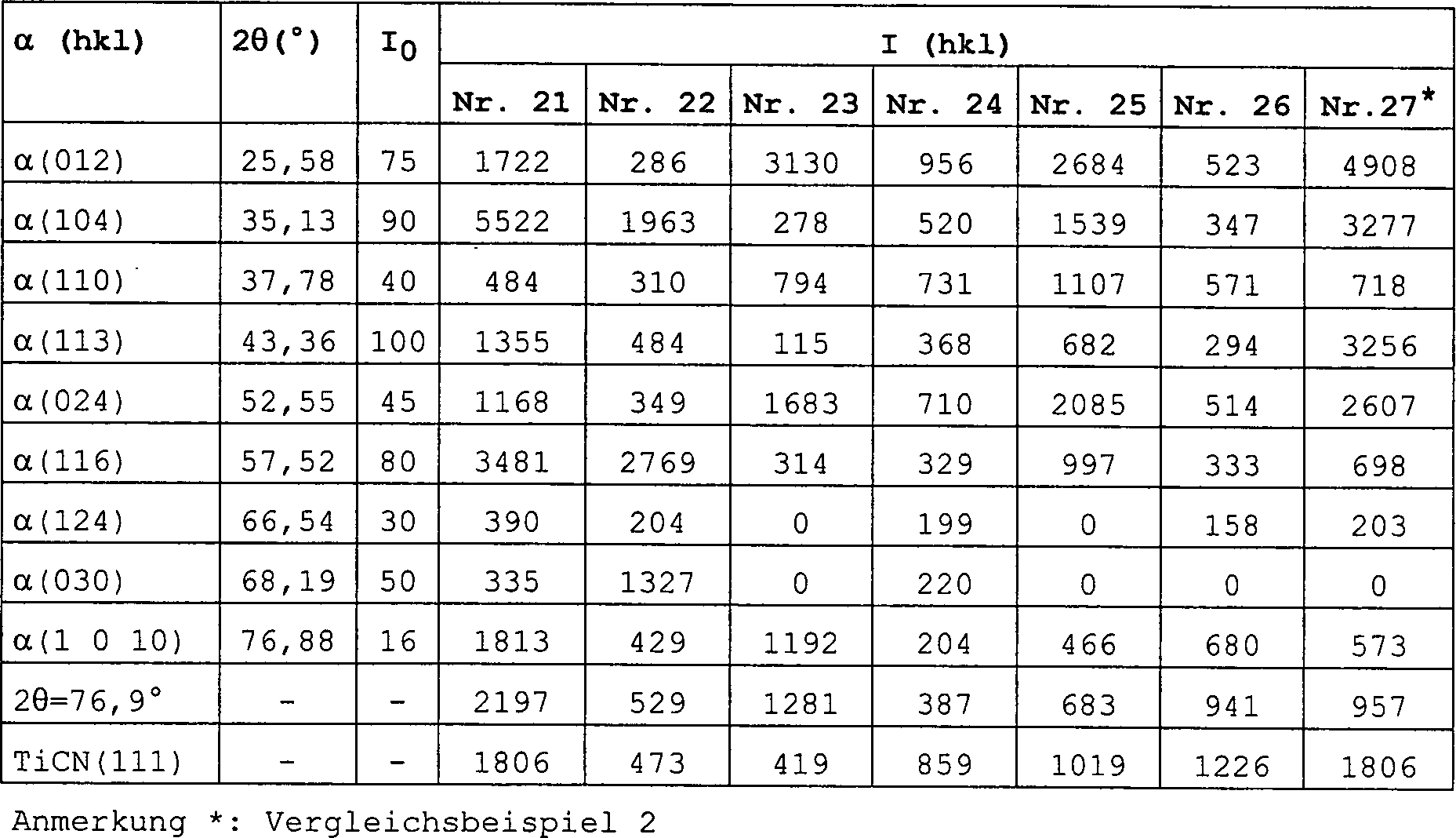
Tabelle
8 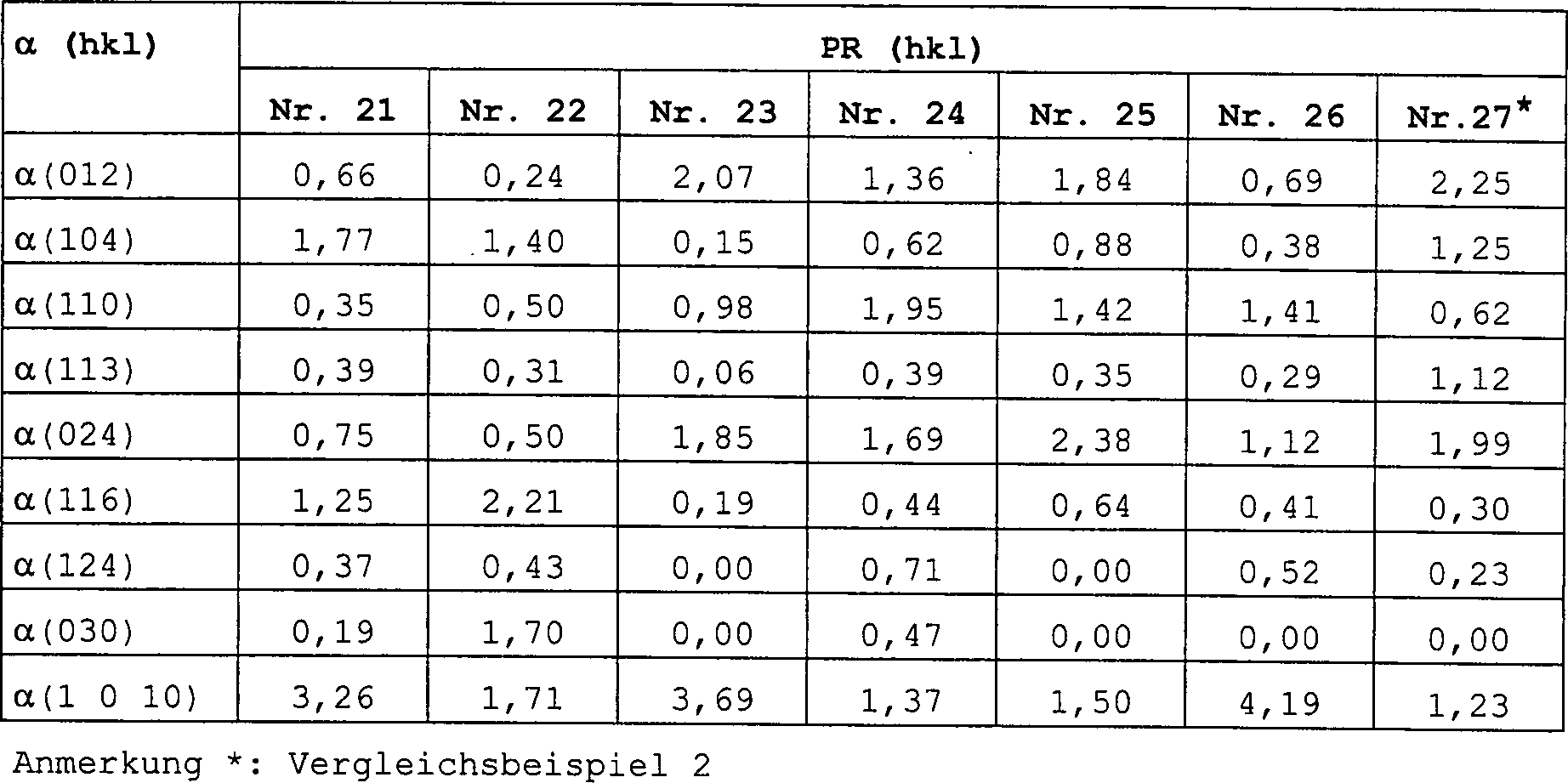
Tabelle
9 
Wie vorstehend ausgeführt, ist der erfindungsgemäße, mit Aluminiumoxid beschichtete Gegenstand aufgrund der Tatsache, dass er eine einlagige oder mehrlagige Beschichtung aus mindestens einem Bestandteil, der aus der Gruppe Carbide, Nitride, Carbonitride, Oxide, Oxycarbide, Oxynitride und Oxycarbonitride von Metallen der Gruppen IVa, Va und VIa des Periodensystems ausgewählt ist und eine Oxidschicht auf der Basis von α-Aluminiumoxid mit einem äquivalenten Röntgenbeugungs-Peakverhältnis PR (1 0 10) von 1,3 oder mehr aufweist, mit einer α-Aluminiumoxidschicht ausgestattet, die eine geringe Kristallkorngröße besitzt, was zu hervorragenden Schneideeigenschaften führt.As stated above, is the inventive, with Alumina coated article due to the fact that he a single-layer or multi-layer coating of at least one Constituent of the group carbides, nitrides, carbonitrides, Oxides, oxycarbides, oxynitrides and oxycarbonitrides of metals of Groups IVa, Va and VIa of the Periodic Table is selected and an oxide layer based on α-alumina with an equivalent X-ray diffraction peak ratio PR (1 0 10) of 1.3 or more, provided with an α-alumina layer, which has a small crystal grain size, which leads to excellent cutting properties.
Claims (6)
Applications Claiming Priority (2)
| Application Number | Priority Date | Filing Date | Title |
|---|---|---|---|
| JP33020398A JP3678924B2 (en) | 1998-11-05 | 1998-11-05 | Aluminum oxide coated tool |
| JP33020398 | 1998-11-05 |
Publications (2)
| Publication Number | Publication Date |
|---|---|
| DE69918397D1 DE69918397D1 (en) | 2004-08-05 |
| DE69918397T2 true DE69918397T2 (en) | 2005-02-17 |
Family
ID=18230002
Family Applications (1)
| Application Number | Title | Priority Date | Filing Date |
|---|---|---|---|
| DE69918397T Expired - Lifetime DE69918397T2 (en) | 1998-11-05 | 1999-11-04 | Alumina coated article |
Country Status (4)
| Country | Link |
|---|---|
| US (1) | US6333103B1 (en) |
| EP (1) | EP0999293B1 (en) |
| JP (1) | JP3678924B2 (en) |
| DE (1) | DE69918397T2 (en) |
Families Citing this family (58)
| Publication number | Priority date | Publication date | Assignee | Title |
|---|---|---|---|---|
| IL145465A (en) * | 1999-06-21 | 2005-03-20 | Sumitomo Electric Industries | Coated hard alloy |
| SE519339C2 (en) * | 2000-11-22 | 2003-02-18 | Sandvik Ab | Cutting tools coated with alumina and ways of manufacturing the same |
| SE522736C2 (en) * | 2001-02-16 | 2004-03-02 | Sandvik Ab | Aluminum-coated cutting tool and method for making the same |
| SE525581C2 (en) * | 2002-05-08 | 2005-03-15 | Seco Tools Ab | Cutting coated with alumina made with CVD |
| US7535017B2 (en) * | 2003-05-30 | 2009-05-19 | Osram Opto Semiconductors Gmbh | Flexible multilayer packaging material and electronic devices with the packaging material |
| US7455918B2 (en) * | 2004-03-12 | 2008-11-25 | Kennametal Inc. | Alumina coating, coated product and method of making the same |
| KR100600573B1 (en) * | 2004-06-30 | 2006-07-13 | 한국야금 주식회사 | Surface-coated hard member for cutting tools / wear resistant tools |
| JP2006028600A (en) * | 2004-07-16 | 2006-02-02 | Kobe Steel Ltd | Stacked film having excellent wear resistance and heat resistance |
| US7579042B2 (en) * | 2004-07-29 | 2009-08-25 | Wisconsin Alumni Research Foundation | Methods for the fabrication of thermally stable magnetic tunnel junctions |
| JP4529638B2 (en) * | 2004-10-27 | 2010-08-25 | 三菱マテリアル株式会社 | Cutting tool made of surface-coated cemented carbide that provides excellent chipping resistance with a hard coating layer in high-speed heavy cutting |
| SE528430C2 (en) * | 2004-11-05 | 2006-11-14 | Seco Tools Ab | With aluminum oxide coated cutting tool inserts and method of making this |
| SE528432C2 (en) | 2004-11-05 | 2006-11-14 | Seco Tools Ab | With aluminum oxide coated cutting tool inserts and method for making this |
| SE528431C2 (en) * | 2004-11-05 | 2006-11-14 | Seco Tools Ab | With aluminum oxide coated cutting tool inserts and method of making this |
| JP4730702B2 (en) * | 2005-04-26 | 2011-07-20 | 三菱マテリアル株式会社 | Surface-coated cermet cutting tool with excellent chipping resistance thanks to thick α-type aluminum oxide layer |
| SE529051C2 (en) * | 2005-09-27 | 2007-04-17 | Seco Tools Ab | Cutting tool inserts coated with alumina |
| EP1788124B1 (en) * | 2005-11-18 | 2008-09-24 | Mitsubishi Materials Corporation | Surface coated cutting tool made of cermet having property-modified alpha type Al2O3 layer of hard coating layer |
| JP4888771B2 (en) * | 2006-11-17 | 2012-02-29 | 三菱マテリアル株式会社 | Surface coated cutting tool with excellent chipping resistance due to hard coating layer |
| SE531670C2 (en) * | 2007-02-01 | 2009-06-30 | Seco Tools Ab | Textured alpha-alumina coated cutting for metalworking |
| SE532023C2 (en) * | 2007-02-01 | 2009-09-29 | Seco Tools Ab | Textured hardened alpha-alumina coated cutting for metalworking |
| SE531929C2 (en) * | 2007-07-13 | 2009-09-08 | Seco Tools Ab | Coated cemented carbide inserts for turning steel or stainless steel |
| US8833174B2 (en) * | 2007-04-12 | 2014-09-16 | Colorado School Of Mines | Piezoelectric sensor based smart-die structure for predicting the onset of failure during die casting operations |
| US8080323B2 (en) * | 2007-06-28 | 2011-12-20 | Kennametal Inc. | Cutting insert with a wear-resistant coating scheme exhibiting wear indication and method of making the same |
| US20090004449A1 (en) * | 2007-06-28 | 2009-01-01 | Zhigang Ban | Cutting insert with a wear-resistant coating scheme exhibiting wear indication and method of making the same |
| JP5229683B2 (en) * | 2008-03-18 | 2013-07-03 | 日立ツール株式会社 | Coated tool |
| EP2143819A1 (en) * | 2008-07-11 | 2010-01-13 | Siemens Aktiengesellschaft | Coating method and corrosion protection coating for turbine components |
| IT1399805B1 (en) * | 2009-03-27 | 2013-05-03 | Torino Politecnico | PROCEDURE FOR COATING ALUMINUM ALLOY DETAILS, IN PARTICULAR IN PRESSOCOLATE ALUMINUM ALLOY, AND DETAILS MADE THROUGH THIS PROCEDURE |
| CN102612417A (en) * | 2009-11-06 | 2012-07-25 | 株式会社图格莱 | Coated tool |
| JP5333418B2 (en) * | 2010-03-31 | 2013-11-06 | 日立ツール株式会社 | Manufacturing method of hard coating tool |
| EP2395126A1 (en) | 2010-06-08 | 2011-12-14 | Seco Tools AB | Textured alumina layer |
| EP2446988A1 (en) | 2010-10-29 | 2012-05-02 | Seco Tools AB | Cutting tool insert with an alpha-alumina layer having a multi-components texture |
| WO2012079769A1 (en) | 2010-12-17 | 2012-06-21 | Seco Tools Ab | Coated cubic boron nitride tool for machining applications |
| US8968866B2 (en) * | 2011-05-10 | 2015-03-03 | Sumitomo Electric Hardmetal Corp. | Surface-coated cutting tool |
| US8179028B1 (en) | 2011-08-08 | 2012-05-15 | Rao Dantam K | Prevention of core failures in large electric machines |
| US9488184B2 (en) | 2012-05-02 | 2016-11-08 | King Abdulaziz City For Science And Technology | Method and system of increasing wear resistance of a part of a rotating mechanism exposed to fluid flow therethrough |
| DE112014001562B4 (en) | 2013-03-21 | 2019-08-08 | Kennametal Inc. | Coatings for cutting tools |
| US9181620B2 (en) | 2013-03-21 | 2015-11-10 | Kennametal Inc. | Coatings for cutting tools |
| US9371580B2 (en) | 2013-03-21 | 2016-06-21 | Kennametal Inc. | Coated body wherein the coating scheme includes a coating layer of TiAl2O3 and method of making the same |
| CN105517738B (en) * | 2013-08-27 | 2017-11-10 | 京瓷株式会社 | coated tool |
| WO2015111752A1 (en) * | 2014-01-27 | 2015-07-30 | 株式会社タンガロイ | Coated cutting tool |
| KR102375081B1 (en) | 2014-01-30 | 2022-03-15 | 산드빅 인터렉츄얼 프로퍼티 에이비 | Alumina coated cutting tool |
| ES2586479T3 (en) | 2014-01-30 | 2016-10-14 | Walter Ag | Alumina coated cutting tool with zigzag alumina grain boundaries |
| JP6563708B2 (en) * | 2014-06-30 | 2019-08-21 | 日本タングステン株式会社 | Thin film magnetic head substrate, magnetic head slider, and hard disk drive device |
| JP6563710B2 (en) * | 2014-06-30 | 2019-08-21 | 日本タングステン株式会社 | Thin film magnetic head substrate, magnetic head slider, and hard disk drive device |
| JP6563709B2 (en) * | 2014-06-30 | 2019-08-21 | 日本タングステン株式会社 | Thin film magnetic head substrate, magnetic head slider, and hard disk drive device |
| US9719175B2 (en) | 2014-09-30 | 2017-08-01 | Kennametal Inc. | Multilayer structured coatings for cutting tools |
| US9650712B2 (en) | 2014-12-08 | 2017-05-16 | Kennametal Inc. | Inter-anchored multilayer refractory coatings |
| US9650714B2 (en) | 2014-12-08 | 2017-05-16 | Kennametal Inc. | Nanocomposite refractory coatings and applications thereof |
| JP6522985B2 (en) * | 2015-02-25 | 2019-05-29 | 京セラ株式会社 | Coated tools |
| JP6229911B1 (en) * | 2016-10-19 | 2017-11-15 | 株式会社タンガロイ | Coated cutting tool |
| JP6229912B1 (en) * | 2016-10-21 | 2017-11-15 | 株式会社タンガロイ | Coated cutting tool |
| CN109963674B (en) * | 2016-11-17 | 2021-07-06 | 株式会社泰珂洛 | Coated Cutting Tools |
| US10946454B2 (en) * | 2017-01-07 | 2021-03-16 | Tungaloy Corporation | Coated cutting tool |
| RU2760426C2 (en) * | 2017-04-07 | 2021-11-25 | Сандвик Интеллекчуал Проперти Аб | Cutting tool equipped with coating |
| WO2020050261A1 (en) * | 2018-09-05 | 2020-03-12 | 京セラ株式会社 | Coated tool and cutting tool |
| CN110109328A (en) * | 2019-06-04 | 2019-08-09 | 深圳市科洛德打印耗材有限公司 | A kind of manufacturing process of long-life high-resolution wide cut diameter printer toner cartridge |
| EP3848484A3 (en) | 2020-01-10 | 2021-09-15 | Sakari Ruppi | Improved alumina layer deposited at low temperature |
| EP3848485A1 (en) | 2020-01-10 | 2021-07-14 | Sakari Ruppi | Improved alpha alumina layer deposited with controlled textures |
| CN115074696B (en) * | 2022-06-29 | 2023-09-29 | 厦门金鹭特种合金有限公司 | Alumina composite coating, preparation method thereof and cutting device |
Family Cites Families (11)
| Publication number | Priority date | Publication date | Assignee | Title |
|---|---|---|---|---|
| SE357984B (en) * | 1971-11-12 | 1973-07-16 | Sandvik Ab | |
| SE367217B (en) * | 1973-09-17 | 1974-05-20 | Sandvik Ab | |
| SE464818B (en) * | 1989-06-16 | 1991-06-17 | Sandvik Ab | COVERED SHOULD BE CUTTING |
| DE69007885T2 (en) * | 1989-07-13 | 1994-07-28 | Seco Tools Ab | Carbide body coated with several oxides and process for its production. |
| JP3408267B2 (en) | 1992-04-17 | 2003-05-19 | 東芝タンガロイ株式会社 | Multi-layer coated sintered alloy with crystal orientation |
| SE501527C2 (en) | 1992-12-18 | 1995-03-06 | Sandvik Ab | Methods and articles when coating a cutting tool with an alumina layer |
| SE502174C2 (en) * | 1993-12-23 | 1995-09-04 | Sandvik Ab | Methods and articles when coating a cutting tool with an alumina layer |
| SE502223C2 (en) | 1994-01-14 | 1995-09-18 | Sandvik Ab | Methods and articles when coating a cutting tool with an alumina layer |
| SE504968C2 (en) | 1994-11-15 | 1997-06-02 | Sandvik Ab | Method of coating a cutting tool with a layer of alpha-Al2O3 |
| JP3418066B2 (en) * | 1996-07-03 | 2003-06-16 | 日立金属株式会社 | Alumina-coated tool and manufacturing method thereof |
| JP3560303B2 (en) | 1996-11-29 | 2004-09-02 | 日立金属株式会社 | Aluminum oxide coated tool and method of manufacturing the same |
-
1998
- 1998-11-05 JP JP33020398A patent/JP3678924B2/en not_active Expired - Lifetime
-
1999
- 1999-11-04 EP EP99121867A patent/EP0999293B1/en not_active Expired - Lifetime
- 1999-11-04 DE DE69918397T patent/DE69918397T2/en not_active Expired - Lifetime
- 1999-11-05 US US09/434,176 patent/US6333103B1/en not_active Expired - Lifetime
Also Published As
| Publication number | Publication date |
|---|---|
| EP0999293B1 (en) | 2004-06-30 |
| DE69918397D1 (en) | 2004-08-05 |
| US6333103B1 (en) | 2001-12-25 |
| JP3678924B2 (en) | 2005-08-03 |
| JP2000144427A (en) | 2000-05-26 |
| EP0999293A1 (en) | 2000-05-10 |
Similar Documents
| Publication | Publication Date | Title |
|---|---|---|
| DE69918397T2 (en) | Alumina coated article | |
| DE69521410T2 (en) | COATED HARD ALLOY | |
| DE69606109T2 (en) | Coated cutting insert | |
| DE60105739T2 (en) | Oxide coated cutting tool | |
| DE60225965T2 (en) | Alpha-alumina coated cutting tool | |
| DE102018112535B4 (en) | CVD COMPOSITE REFRACTORY COATINGS AND THEIR APPLICATIONS | |
| DE69617767T2 (en) | Sintered carbide substrate with multilayers made of aluminum | |
| DE102017117008B4 (en) | COMPOSITE REFRACTORY COATINGS | |
| DE69828453T2 (en) | PVD-Al2O3 coated cutting tool | |
| DE69509218T3 (en) | OXIDE-COATED CUTTING TOOL | |
| DE69518039T2 (en) | Coated carbide alloy blade | |
| DE69738341T2 (en) | Alumina-coated tool and process for its production | |
| DE69306089T2 (en) | Cutting tool coated with oxide | |
| DE19651592C5 (en) | Coated cutting tool | |
| DE69527236T2 (en) | Multi-layer film made of ultra-fine particles and hard composite material for tools that contain this film | |
| DE69431032T2 (en) | COATED CUTTING TOOL AND METHOD FOR THE PRODUCTION THEREOF | |
| DE69625934T2 (en) | COATED GRINDING INSERT AND METHOD FOR THE PRODUCTION THEREOF | |
| DE19980940B4 (en) | Coated carbide cutting tool | |
| EP2499275B1 (en) | Coated bodies made of metal, hard metal, cermet or ceramic material and method for coating such bodies | |
| DE60030524T2 (en) | PVD COATED CUTTING TOOL AND METHOD FOR THE PRODUCTION THEREOF | |
| DE69619275T2 (en) | COATED ROTATABLE INSERT AND METHOD FOR THE PRODUCTION THEREOF | |
| DE69616669T2 (en) | Cutting tool coated with oxide | |
| DE112012003571B4 (en) | CUTTING TOOL | |
| DE102004007653A1 (en) | Surface coated part | |
| DE60300927T2 (en) | Coated cutting tool |
Legal Events
| Date | Code | Title | Description |
|---|---|---|---|
| 8364 | No opposition during term of opposition |