DE69916312T2 - METHOD AND DEVICE FOR TREATING COMBUSTION GASES - Google Patents
METHOD AND DEVICE FOR TREATING COMBUSTION GASES Download PDFInfo
- Publication number
- DE69916312T2 DE69916312T2 DE69916312T DE69916312T DE69916312T2 DE 69916312 T2 DE69916312 T2 DE 69916312T2 DE 69916312 T DE69916312 T DE 69916312T DE 69916312 T DE69916312 T DE 69916312T DE 69916312 T2 DE69916312 T2 DE 69916312T2
- Authority
- DE
- Germany
- Prior art keywords
- absorbent
- catalyst
- filter
- absorber
- reactant
- Prior art date
- Legal status (The legal status is an assumption and is not a legal conclusion. Google has not performed a legal analysis and makes no representation as to the accuracy of the status listed.)
- Expired - Lifetime
Links
Classifications
-
- F—MECHANICAL ENGINEERING; LIGHTING; HEATING; WEAPONS; BLASTING
- F01—MACHINES OR ENGINES IN GENERAL; ENGINE PLANTS IN GENERAL; STEAM ENGINES
- F01N—GAS-FLOW SILENCERS OR EXHAUST APPARATUS FOR MACHINES OR ENGINES IN GENERAL; GAS-FLOW SILENCERS OR EXHAUST APPARATUS FOR INTERNAL COMBUSTION ENGINES
- F01N3/00—Exhaust or silencing apparatus having means for purifying, rendering innocuous, or otherwise treating exhaust
- F01N3/08—Exhaust or silencing apparatus having means for purifying, rendering innocuous, or otherwise treating exhaust for rendering innocuous
- F01N3/0807—Exhaust or silencing apparatus having means for purifying, rendering innocuous, or otherwise treating exhaust for rendering innocuous by using absorbents or adsorbents
- F01N3/0871—Regulation of absorbents or adsorbents, e.g. purging
-
- B—PERFORMING OPERATIONS; TRANSPORTING
- B01—PHYSICAL OR CHEMICAL PROCESSES OR APPARATUS IN GENERAL
- B01D—SEPARATION
- B01D53/00—Separation of gases or vapours; Recovering vapours of volatile solvents from gases; Chemical or biological purification of waste gases, e.g. engine exhaust gases, smoke, fumes, flue gases, aerosols
- B01D53/34—Chemical or biological purification of waste gases
- B01D53/92—Chemical or biological purification of waste gases of engine exhaust gases
- B01D53/94—Chemical or biological purification of waste gases of engine exhaust gases by catalytic processes
- B01D53/9404—Removing only nitrogen compounds
- B01D53/9409—Nitrogen oxides
- B01D53/9431—Processes characterised by a specific device
-
- B—PERFORMING OPERATIONS; TRANSPORTING
- B01—PHYSICAL OR CHEMICAL PROCESSES OR APPARATUS IN GENERAL
- B01D—SEPARATION
- B01D53/00—Separation of gases or vapours; Recovering vapours of volatile solvents from gases; Chemical or biological purification of waste gases, e.g. engine exhaust gases, smoke, fumes, flue gases, aerosols
- B01D53/34—Chemical or biological purification of waste gases
- B01D53/92—Chemical or biological purification of waste gases of engine exhaust gases
- B01D53/94—Chemical or biological purification of waste gases of engine exhaust gases by catalytic processes
- B01D53/9445—Simultaneously removing carbon monoxide, hydrocarbons or nitrogen oxides making use of three-way catalysts [TWC] or four-way-catalysts [FWC]
- B01D53/9454—Simultaneously removing carbon monoxide, hydrocarbons or nitrogen oxides making use of three-way catalysts [TWC] or four-way-catalysts [FWC] characterised by a specific device
-
- F—MECHANICAL ENGINEERING; LIGHTING; HEATING; WEAPONS; BLASTING
- F01—MACHINES OR ENGINES IN GENERAL; ENGINE PLANTS IN GENERAL; STEAM ENGINES
- F01N—GAS-FLOW SILENCERS OR EXHAUST APPARATUS FOR MACHINES OR ENGINES IN GENERAL; GAS-FLOW SILENCERS OR EXHAUST APPARATUS FOR INTERNAL COMBUSTION ENGINES
- F01N3/00—Exhaust or silencing apparatus having means for purifying, rendering innocuous, or otherwise treating exhaust
- F01N3/02—Exhaust or silencing apparatus having means for purifying, rendering innocuous, or otherwise treating exhaust for cooling, or for removing solid constituents of, exhaust
- F01N3/021—Exhaust or silencing apparatus having means for purifying, rendering innocuous, or otherwise treating exhaust for cooling, or for removing solid constituents of, exhaust by means of filters
- F01N3/023—Exhaust or silencing apparatus having means for purifying, rendering innocuous, or otherwise treating exhaust for cooling, or for removing solid constituents of, exhaust by means of filters using means for regenerating the filters, e.g. by burning trapped particles
- F01N3/0231—Exhaust or silencing apparatus having means for purifying, rendering innocuous, or otherwise treating exhaust for cooling, or for removing solid constituents of, exhaust by means of filters using means for regenerating the filters, e.g. by burning trapped particles using special exhaust apparatus upstream of the filter for producing nitrogen dioxide, e.g. for continuous filter regeneration systems [CRT]
-
- F—MECHANICAL ENGINEERING; LIGHTING; HEATING; WEAPONS; BLASTING
- F01—MACHINES OR ENGINES IN GENERAL; ENGINE PLANTS IN GENERAL; STEAM ENGINES
- F01N—GAS-FLOW SILENCERS OR EXHAUST APPARATUS FOR MACHINES OR ENGINES IN GENERAL; GAS-FLOW SILENCERS OR EXHAUST APPARATUS FOR INTERNAL COMBUSTION ENGINES
- F01N3/00—Exhaust or silencing apparatus having means for purifying, rendering innocuous, or otherwise treating exhaust
- F01N3/02—Exhaust or silencing apparatus having means for purifying, rendering innocuous, or otherwise treating exhaust for cooling, or for removing solid constituents of, exhaust
- F01N3/021—Exhaust or silencing apparatus having means for purifying, rendering innocuous, or otherwise treating exhaust for cooling, or for removing solid constituents of, exhaust by means of filters
- F01N3/023—Exhaust or silencing apparatus having means for purifying, rendering innocuous, or otherwise treating exhaust for cooling, or for removing solid constituents of, exhaust by means of filters using means for regenerating the filters, e.g. by burning trapped particles
- F01N3/029—Exhaust or silencing apparatus having means for purifying, rendering innocuous, or otherwise treating exhaust for cooling, or for removing solid constituents of, exhaust by means of filters using means for regenerating the filters, e.g. by burning trapped particles by adding non-fuel substances to exhaust
-
- F—MECHANICAL ENGINEERING; LIGHTING; HEATING; WEAPONS; BLASTING
- F01—MACHINES OR ENGINES IN GENERAL; ENGINE PLANTS IN GENERAL; STEAM ENGINES
- F01N—GAS-FLOW SILENCERS OR EXHAUST APPARATUS FOR MACHINES OR ENGINES IN GENERAL; GAS-FLOW SILENCERS OR EXHAUST APPARATUS FOR INTERNAL COMBUSTION ENGINES
- F01N3/00—Exhaust or silencing apparatus having means for purifying, rendering innocuous, or otherwise treating exhaust
- F01N3/02—Exhaust or silencing apparatus having means for purifying, rendering innocuous, or otherwise treating exhaust for cooling, or for removing solid constituents of, exhaust
- F01N3/021—Exhaust or silencing apparatus having means for purifying, rendering innocuous, or otherwise treating exhaust for cooling, or for removing solid constituents of, exhaust by means of filters
- F01N3/033—Exhaust or silencing apparatus having means for purifying, rendering innocuous, or otherwise treating exhaust for cooling, or for removing solid constituents of, exhaust by means of filters in combination with other devices
- F01N3/035—Exhaust or silencing apparatus having means for purifying, rendering innocuous, or otherwise treating exhaust for cooling, or for removing solid constituents of, exhaust by means of filters in combination with other devices with catalytic reactors, e.g. catalysed diesel particulate filters
-
- F—MECHANICAL ENGINEERING; LIGHTING; HEATING; WEAPONS; BLASTING
- F01—MACHINES OR ENGINES IN GENERAL; ENGINE PLANTS IN GENERAL; STEAM ENGINES
- F01N—GAS-FLOW SILENCERS OR EXHAUST APPARATUS FOR MACHINES OR ENGINES IN GENERAL; GAS-FLOW SILENCERS OR EXHAUST APPARATUS FOR INTERNAL COMBUSTION ENGINES
- F01N3/00—Exhaust or silencing apparatus having means for purifying, rendering innocuous, or otherwise treating exhaust
- F01N3/08—Exhaust or silencing apparatus having means for purifying, rendering innocuous, or otherwise treating exhaust for rendering innocuous
- F01N3/0807—Exhaust or silencing apparatus having means for purifying, rendering innocuous, or otherwise treating exhaust for rendering innocuous by using absorbents or adsorbents
- F01N3/0814—Exhaust or silencing apparatus having means for purifying, rendering innocuous, or otherwise treating exhaust for rendering innocuous by using absorbents or adsorbents combined with catalytic converters, e.g. NOx absorption/storage reduction catalysts
-
- F—MECHANICAL ENGINEERING; LIGHTING; HEATING; WEAPONS; BLASTING
- F01—MACHINES OR ENGINES IN GENERAL; ENGINE PLANTS IN GENERAL; STEAM ENGINES
- F01N—GAS-FLOW SILENCERS OR EXHAUST APPARATUS FOR MACHINES OR ENGINES IN GENERAL; GAS-FLOW SILENCERS OR EXHAUST APPARATUS FOR INTERNAL COMBUSTION ENGINES
- F01N3/00—Exhaust or silencing apparatus having means for purifying, rendering innocuous, or otherwise treating exhaust
- F01N3/08—Exhaust or silencing apparatus having means for purifying, rendering innocuous, or otherwise treating exhaust for rendering innocuous
- F01N3/0807—Exhaust or silencing apparatus having means for purifying, rendering innocuous, or otherwise treating exhaust for rendering innocuous by using absorbents or adsorbents
- F01N3/0821—Exhaust or silencing apparatus having means for purifying, rendering innocuous, or otherwise treating exhaust for rendering innocuous by using absorbents or adsorbents combined with particulate filters
-
- F—MECHANICAL ENGINEERING; LIGHTING; HEATING; WEAPONS; BLASTING
- F01—MACHINES OR ENGINES IN GENERAL; ENGINE PLANTS IN GENERAL; STEAM ENGINES
- F01N—GAS-FLOW SILENCERS OR EXHAUST APPARATUS FOR MACHINES OR ENGINES IN GENERAL; GAS-FLOW SILENCERS OR EXHAUST APPARATUS FOR INTERNAL COMBUSTION ENGINES
- F01N2250/00—Combinations of different methods of purification
- F01N2250/02—Combinations of different methods of purification filtering and catalytic conversion
-
- F—MECHANICAL ENGINEERING; LIGHTING; HEATING; WEAPONS; BLASTING
- F01—MACHINES OR ENGINES IN GENERAL; ENGINE PLANTS IN GENERAL; STEAM ENGINES
- F01N—GAS-FLOW SILENCERS OR EXHAUST APPARATUS FOR MACHINES OR ENGINES IN GENERAL; GAS-FLOW SILENCERS OR EXHAUST APPARATUS FOR INTERNAL COMBUSTION ENGINES
- F01N2250/00—Combinations of different methods of purification
- F01N2250/12—Combinations of different methods of purification absorption or adsorption, and catalytic conversion
-
- F—MECHANICAL ENGINEERING; LIGHTING; HEATING; WEAPONS; BLASTING
- F01—MACHINES OR ENGINES IN GENERAL; ENGINE PLANTS IN GENERAL; STEAM ENGINES
- F01N—GAS-FLOW SILENCERS OR EXHAUST APPARATUS FOR MACHINES OR ENGINES IN GENERAL; GAS-FLOW SILENCERS OR EXHAUST APPARATUS FOR INTERNAL COMBUSTION ENGINES
- F01N2250/00—Combinations of different methods of purification
- F01N2250/14—Combinations of different methods of purification absorption or adsorption, and filtering
-
- F—MECHANICAL ENGINEERING; LIGHTING; HEATING; WEAPONS; BLASTING
- F01—MACHINES OR ENGINES IN GENERAL; ENGINE PLANTS IN GENERAL; STEAM ENGINES
- F01N—GAS-FLOW SILENCERS OR EXHAUST APPARATUS FOR MACHINES OR ENGINES IN GENERAL; GAS-FLOW SILENCERS OR EXHAUST APPARATUS FOR INTERNAL COMBUSTION ENGINES
- F01N2610/00—Adding substances to exhaust gases
- F01N2610/02—Adding substances to exhaust gases the substance being ammonia or urea
-
- F—MECHANICAL ENGINEERING; LIGHTING; HEATING; WEAPONS; BLASTING
- F01—MACHINES OR ENGINES IN GENERAL; ENGINE PLANTS IN GENERAL; STEAM ENGINES
- F01N—GAS-FLOW SILENCERS OR EXHAUST APPARATUS FOR MACHINES OR ENGINES IN GENERAL; GAS-FLOW SILENCERS OR EXHAUST APPARATUS FOR INTERNAL COMBUSTION ENGINES
- F01N2610/00—Adding substances to exhaust gases
- F01N2610/03—Adding substances to exhaust gases the substance being hydrocarbons, e.g. engine fuel
-
- F—MECHANICAL ENGINEERING; LIGHTING; HEATING; WEAPONS; BLASTING
- F01—MACHINES OR ENGINES IN GENERAL; ENGINE PLANTS IN GENERAL; STEAM ENGINES
- F01N—GAS-FLOW SILENCERS OR EXHAUST APPARATUS FOR MACHINES OR ENGINES IN GENERAL; GAS-FLOW SILENCERS OR EXHAUST APPARATUS FOR INTERNAL COMBUSTION ENGINES
- F01N3/00—Exhaust or silencing apparatus having means for purifying, rendering innocuous, or otherwise treating exhaust
- F01N3/08—Exhaust or silencing apparatus having means for purifying, rendering innocuous, or otherwise treating exhaust for rendering innocuous
- F01N3/10—Exhaust or silencing apparatus having means for purifying, rendering innocuous, or otherwise treating exhaust for rendering innocuous by thermal or catalytic conversion of noxious components of exhaust
- F01N3/18—Exhaust or silencing apparatus having means for purifying, rendering innocuous, or otherwise treating exhaust for rendering innocuous by thermal or catalytic conversion of noxious components of exhaust characterised by methods of operation; Control
- F01N3/22—Control of additional air supply only, e.g. using by-passes or variable air pump drives
-
- Y—GENERAL TAGGING OF NEW TECHNOLOGICAL DEVELOPMENTS; GENERAL TAGGING OF CROSS-SECTIONAL TECHNOLOGIES SPANNING OVER SEVERAL SECTIONS OF THE IPC; TECHNICAL SUBJECTS COVERED BY FORMER USPC CROSS-REFERENCE ART COLLECTIONS [XRACs] AND DIGESTS
- Y02—TECHNOLOGIES OR APPLICATIONS FOR MITIGATION OR ADAPTATION AGAINST CLIMATE CHANGE
- Y02A—TECHNOLOGIES FOR ADAPTATION TO CLIMATE CHANGE
- Y02A50/00—TECHNOLOGIES FOR ADAPTATION TO CLIMATE CHANGE in human health protection, e.g. against extreme weather
- Y02A50/20—Air quality improvement or preservation, e.g. vehicle emission control or emission reduction by using catalytic converters
-
- Y—GENERAL TAGGING OF NEW TECHNOLOGICAL DEVELOPMENTS; GENERAL TAGGING OF CROSS-SECTIONAL TECHNOLOGIES SPANNING OVER SEVERAL SECTIONS OF THE IPC; TECHNICAL SUBJECTS COVERED BY FORMER USPC CROSS-REFERENCE ART COLLECTIONS [XRACs] AND DIGESTS
- Y02—TECHNOLOGIES OR APPLICATIONS FOR MITIGATION OR ADAPTATION AGAINST CLIMATE CHANGE
- Y02C—CAPTURE, STORAGE, SEQUESTRATION OR DISPOSAL OF GREENHOUSE GASES [GHG]
- Y02C20/00—Capture or disposal of greenhouse gases
- Y02C20/40—Capture or disposal of greenhouse gases of CO2
-
- Y—GENERAL TAGGING OF NEW TECHNOLOGICAL DEVELOPMENTS; GENERAL TAGGING OF CROSS-SECTIONAL TECHNOLOGIES SPANNING OVER SEVERAL SECTIONS OF THE IPC; TECHNICAL SUBJECTS COVERED BY FORMER USPC CROSS-REFERENCE ART COLLECTIONS [XRACs] AND DIGESTS
- Y02—TECHNOLOGIES OR APPLICATIONS FOR MITIGATION OR ADAPTATION AGAINST CLIMATE CHANGE
- Y02T—CLIMATE CHANGE MITIGATION TECHNOLOGIES RELATED TO TRANSPORTATION
- Y02T10/00—Road transport of goods or passengers
- Y02T10/10—Internal combustion engine [ICE] based vehicles
- Y02T10/12—Improving ICE efficiencies
Landscapes
- Engineering & Computer Science (AREA)
- Chemical & Material Sciences (AREA)
- Combustion & Propulsion (AREA)
- Mechanical Engineering (AREA)
- General Engineering & Computer Science (AREA)
- Chemical Kinetics & Catalysis (AREA)
- Analytical Chemistry (AREA)
- Environmental & Geological Engineering (AREA)
- Biomedical Technology (AREA)
- General Chemical & Material Sciences (AREA)
- Oil, Petroleum & Natural Gas (AREA)
- Health & Medical Sciences (AREA)
- Exhaust Gas After Treatment (AREA)
- Exhaust Gas Treatment By Means Of Catalyst (AREA)
- Incineration Of Waste (AREA)
- Chimneys And Flues (AREA)
- Filtering Of Dispersed Particles In Gases (AREA)
- Solid-Sorbent Or Filter-Aiding Compositions (AREA)
Abstract
Description
Diese Erfindung betrifft die Abgas- bzw. Emissionskontrolle insbesondere für Dieselmotor-Abgas.These The invention relates in particular to the emission control for diesel engine exhaust.
EP-A-0 341 832 und das entsprechende US-A-4 902 487 beschreiben ein Verfahren und ein Behandlungssystem zur Entfernung von Ruß aus Dieselabgas, das NO enthält, durch Überleiten dieses unfiltrierten Gases über einen Oxidationskatalysator, um NO in NO2 umzuwandeln, Sammeln des Rußes auf einem Filter und Verwendung des resultierenden Gases, das NO2 enthält, zum Verbrennen des gesammelten Rußes, wobei die Menge des in NO2 umgewandelten NO ausreicht, um diese Verbrennung bei einer Temperatur von weniger als 400°C ablaufen zu lassen. Diese Dokumente beschreiben eine Anordnung, die von der Firma Johnson Matthey Plc unter der Bezeichnung CRT® auf den Markt gebracht worden ist.EP-A-0 341 832 and corresponding US-A-4 902 487 describe a method and a treatment system for removing soot from diesel exhaust gas containing NO by passing this unfiltered gas over an oxidation catalyst to convert NO to NO 2 . Collecting the soot on a filter and using the resulting gas containing NO 2 to combust the collected soot, the amount of NO converted to NO 2 being sufficient to cause this combustion to occur at a temperature of less than 400 ° C. These documents describe an arrangement that has been brought by Johnson Matthey Plc under the name CRT ® to the market.
In EP-A-0 758 713 ist ein Verfahren beschrieben, bei dem auf eine solche Rußverbrennungsstufe folgt die Entfernung von NOx aus dem Verbrennungs-Auslassgas mittels eines festen Absorbens und die Regenerierung des Absorbens durch intermittierende Motor-Treibstoff-Einlasseinstellung oder Injektion eines Reduktionsmittels in den Abgasstrom stromaufwärts von dem Oxidationskatalysator. Dieses Verfahren hat verschiedene Nachteile, beispielsweise den, dass eine Motor-Modifizierung erforderlich ist.In EP-A-0 758 713 a method is described in which such a soot combustion stage is followed by removal of NO x from the combustion outlet gas by means of a solid absorbent and regeneration of the absorbent by intermittent engine fuel inlet adjustment or injection of a reducing agent into the exhaust stream upstream of the oxidation catalyst. This method has several disadvantages, for example, that engine modification is required.
Gegenstand der Erfindung ist ein Verfahren zur Behandlung eines Verbrennungs-Abgases, das CO, Kohlenwasserstoffe (HC), NO, O2, Ruß und nicht-reaktionsfähige Gase enthält, wobei das Verfahren die Stufen umfasst:
- (i) Katalysieren der Oxidation von NO zu NO2;
- (ii) Sammeln von Ruß auf einem Filter;
- (iii) Verbrennen des gesammelten Rußes durch Umsetzung mit NO2 und möglicherweise auch mit O2, das nach der Stufe (i) übrig geblieben ist;
- (iv) Entfernen von NOx aus dem in der Stufe (iii) erhaltenen Gas durch Kontaktieren desselben mit einem regenerierbaren NOx-Absorbens;
- (v) intermittierendes Regenerieren des Absorbens durch Injektion eines NOx- spezifischen Reaktanten stromaufwärts von dem Absorbens; und
- (vi) Inkontaktbringen eines selektiven katalytischen Reduktions(SCR)-Katalysators zumindest während der Stufe (v) mit dem Gas, das in der Stufe (v) erhalten wird.
- (i) catalyzing the oxidation of NO to NO 2 ;
- (ii) collecting soot on a filter;
- (iii) burning the collected soot by reaction with NO 2 and possibly also with O 2 remaining after step (i);
- (iv) removing NO x from the gas obtained in step (iii) by contacting it with a regenerable NO x absorbent;
- (v) intermittently regenerating the absorbent by injecting a NOx-specific reactant upstream of the absorbent; and
- (vi) contacting a selective catalytic reduction (SCR) catalyst at least during step (v) with the gas obtained in step (v).
Gegenstand
der Erfindung ist außerdem
ein System für
die Behandlung von Verbrennungsabgas, das umfasst:
einen Katalysator
für die
Oxidation von NO zu NO2; einen stromabwärts von
dem Oxidationskatalysator angeordneten Filter zum Sammeln von Ruß und zum
Zurückhalten
desselben für
die Verbrennungsreaktion mit dem NO2; einen
NOx-Absorber stromabwärts von dem Filter, wobei der
NOx-Absorber ein festes Absorbens umfasst;
Einrichtungen (
a catalyst for the oxidation of NO to NO 2 ; a filter disposed downstream of the oxidation catalyst for collecting soot and retaining it for the combustion reaction with the NO 2 ; a NO x absorber downstream of the filter, the NO x absorber comprising a solid absorbent; Facilities (
Zusätzlich kann das System übliche Merkmale umfassen, wie z. B. Einrichtungen zur Einstellung der Temperatur des Gases auf den in der nächsten stromabwärts gelegenen chemischen Stufe erforderlichen Wert.In addition, can the system usual Include features such. B. means for adjusting the temperature of the gas on the one in the next downstream required chemical level value.
Das System kann in einem einzigen Gehäuse ("Behälter") angeordnet sein oder es kann in getrennten Gehäusen angeordnet sein entsprechend dem Motoraufbau und Unterflur- oder anderen räumlichen Erwägungen. So können beispielsweise für V-Motor-Konfigurationen einige oder alle Elemente des Systems parallel zueinander angeordnet sein.The System can be arranged in a single housing ("container") or it can be in separate housings be arranged according to the engine structure and underfloor or other spatial Considerations. So can for example V-motor configurations parallel some or all elements of the system be arranged to each other.
Die Katalysatoren und das Absorbens sind zweckmäßig auf einen Keramik- oder Metall-Wabenkörper aufgebracht, wobei die Keramik umfasst einen oder mehrere Vertreter aus der Gruppe Aluminiumoxid, Siliciumdioxid, Titandioxid, Cordierit, Cerdioxid, Zirkoniumdioxid, Siliciumcarbid oder irgendein anderes, im Allgemeinen oxidisches Material. Der Wabenkörper trägt einen Washcoat und in Form einer oder mehrerer Schichten darauf das aktive katalytische und/oder absorptionsfähige Material, das weiter unten näher beschrieben wird. Der Wabenkörper weist in der Regel mindestens 7,8 Zellen/cm2 (50 cells/in2), beispielsweise 7,8 bis 62,0 Zellen/cm2 (50–400 cells/in2), möglicherweise mehr, beispielsweise bis zu 124 Zellen/cm2 (800 cells/in2) oder bis zu 186 Zellen/cm2 (1 200 cells/in2) auf, wenn er strukturell aus Metall besteht. Im Allgemeinen ist der Bereich von 31 bis 124 Zellen/cm2 (200–800 cells/in2) für die Katalysatoren und das Absorbens bevorzugt.The catalysts and absorbent are conveniently applied to a ceramic or metal honeycomb body, the ceramic comprising one or more of alumina, silica, titania, cordierite, ceria, zirconia, silicon carbide, or any other generally oxidic material. The honeycomb body wears a washcoat and in the form of one or more layers thereon, the active catalytic and / or absorbent material which will be described in more detail below. The honeycomb body typically has at least 7.8 cells / cm 2 (50 cells / in 2 ), for example 7.8 to 62.0 cells / cm 2 (50-400 cells / in 2 ), possibly more, for example up to 124 cells / cm 2 (800 cells / in 2 ) or up to 186 cells / cm 2 (1,200 cells / in 2 ) if structurally made of metal. In general, the range of 31 to 124 cells / cm 2 (200-800 cells / in 2 ) is preferred for the catalysts and the absorbent.
In dem Oxidationskatalysator umfasst das aktive Material im Allgemeinen ein Platingruppenmetall ("PGM"), insbesondere Platin und/oder Palladium, gegebenenfalls zusammen mit anderen PGMs, beispielsweise Rhodium, und andere katalytische oder Promotor-Komponenten. Die genauen Zusammensetzungen und die Struktur des Oxidationskatalysators sind nicht kritisch für die Durchführung der Erfindung und können daher je nach den Erfordernissen der Situation variiert werden. Eine Niedertemperatur-Starterformulierung ist im Allgemeinen bevorzugt. Es können konventionelle Herstellungsverfahren angewendet werden. Der Katalysator sollte natürlich in Bezug auf Größe und Zusammensetzung so gestaltet sein, dass die erforderlichen Umwandlungen erzielt werden, und das Design sollte das Abscheiden (Einfangen) von Ruß innerhalb seines Wabenkörpers minimieren.In the oxidation catalyst generally comprises the active material a platinum group metal ("PGM"), especially platinum and / or palladium, optionally together with other PGMs, for example Rhodium, and other catalytic or promoter components. The exact compositions and the structure of the oxidation catalyst are not critical for the implementation of the invention and therefore can be varied according to the needs of the situation. A low temperature starter formulation is generally preferred. It can conventional manufacturing processes be applied. The catalyst should of course in terms of size and composition be designed to achieve the required conversions be, and the design should be the deposition (trapping) of soot within his honeycomb body minimize.
Der Filter kann irgendeiner sein, der in der Lage ist, den Ruß abzuscheiden (einzufangen), ohne einen übermäßigen Staudruck zu erzeugen. Im Allgemeinen können Keramik; gesinterte Metall- oder gewebte oder nichtgewebte Drahtfilter verwendet werden und Wandströmungs-Wabenstrukturen können besonders geeignet sein. Das Strukturmaterial des Filters ist vorzugsweise ein poröses Keramikoxid, Siliciumcarbid oder ein gesintertes Metall. Es kann ein Überzug beispielsweise aus Aluminiumoxid und auch ein Katalysator, beispielsweise aus einem oder mehreren PGMs (z. B. Pt mit MgO) oder La/Cs/V2O5 vorhanden sein. Der Ruß besteht im Allgemeinen aus Kohlenstoff und/oder schweren Kohlenwasserstoffen und er wird in Kohlenstoffoxide und H2O umgewandelt. Bestimmte Ausführungsformen dieses Prinzips werden kommerziell angewendet in der Continuous Regenerating Trap (CRT) (in der sich kontinuierlich regenerierenden Fallen-Technologie) der Firma Johnson Matthey und sie sind in den oben genannten Druckschriften EP-A-0 341 832 und US-A-4 902 487 beschrieben.The filter may be any one capable of segregating (trapping) the soot without generating excessive backpressure. In general, ceramics; sintered metal or woven or non-woven wire filters may be used and wall-flow honeycomb structures may be particularly suitable. The structural material of the filter is preferably a porous ceramic oxide, silicon carbide or a sintered metal. A coating of, for example, alumina and also a catalyst, for example of one or more PGMs (eg Pt with MgO) or La / Cs / V 2 O 5 may be present. The carbon black is generally carbon and / or heavy hydrocarbons and is converted to carbon oxides and H 2 O. Certain embodiments of this principle are commercially used in Johnson Matthey Continuous Regenerating Trap (CRT) (Continuously Regenerative Trap Technology) and are described in the above-cited EP-A-0 341 832 and US-A-4 902 487 described.
Das NOx-Absorbens (nachstehend auch als "NOx-Falle" bezeichnet), das weiter unten näher beschrieben wird, kann in einer Einheit oder in einer Aufeinanderfolge von getrennten Einheiten angeordnet sein. Es kann in Form von aktiven Schichten auf einem konventionellen Wabenkörper-Substrat vorliegen oder es kann in Form von seriellen Ablagerungen auf einem einzigen Wabenkörper oder möglicherweise mehreren Wabenkörpern vorliegen.The NO x absorbent (hereinafter also referred to as "NO x trap"), which will be described later, may be arranged in one unit or in a succession of separate units. It may be in the form of active layers on a conventional honeycomb substrate, or it may be in the form of serial deposits on a single honeycomb body or possibly several honeycomb bodies.
Das Absorbens kann ausgewählt werden aus einer Gruppe, die besteht aus:
- (a) Verbindungen von Alkalimetallen, Erdalkalimetallen, Metallen der Seltenen Erden und Übergangsmetallen, die Nitrate und/oder Nitrite mit einer ausreichenden Stabilität unter Absorptionsbedingungen bilden können und Stickstoffoxide und/oder Stickstoff unter Regenerations-Bedingungen entwickeln können; und/oder
- (b) adsorptionsfähigen Materialien, wie z. B. Zeolithen, Kohlesorten und Oxiden mit großer Oberfläche.
- (a) compounds of alkali metals, alkaline earth metals, rare earth metals and transition metals that can form nitrates and / or nitrites with sufficient stability under absorption conditions and can develop nitrogen oxides and / or nitrogen under regeneration conditions; and or
- (B) adsorptive materials, such. As zeolites, coals and oxides with high surface area.
Die Verbindungen (a) können (vor der NOx-Absorption) in Form von zusammengesetzten Oxiden, wie z. B. in Form von Erdalkalimetall- und Kupferoxiden, wie Ba-Cu-O oder MnO2-BaCuO2, möglicherweise mit zugesetz tem Ce-Oxid, oder in Form von Y-Ba-Cu-O und Y-Sr-Co-O vorliegen (die Oxide werden der Einfachheit halber genannt, in der Praxis liegen jedoch Hydroxide, Carbonate und Nitrate vor, je nach Temperatur und Gaszusammensetzung). Unabhängig davon, welche Verbindungen verwendet werden, können auch ein oder mehrere katalytische Agentien, wie z. B. Edelmetalle, vorhanden sein, welche diese Reaktionen als Austauschreaktionen zwischen den Stickstoffoxiden und die Wirkung des Reduktionsmittels und/oder eines NOx-spezifischen Reaktanten fördern.The compounds (a) can (before the NO x absorption) in the form of composite oxides, such as. In the form of alkaline earth metal and copper oxides such as Ba-Cu-O or MnO 2 -BaCuO 2 , possibly with added Ce oxide, or in the form of Y-Ba-Cu-O and Y-Sr-Co-O are present (the oxides are mentioned for the sake of simplicity, in practice, however, are hydroxides, carbonates and nitrates, depending on the temperature and gas composition). Regardless of which compounds are used, one or more catalytic agents, such as. For example, precious metals, which promote these reactions as exchange reactions between the nitrogen oxides and the effect of the reducing agent and / or a NO x -specific reactant.
Der SCR-Katalysator für die Stufe (vi) kann irgendein solcher sein, der bei der vorherrschenden Temperatur aktiv ist und durch die Einwirkung eines mageren Gases zwischen den Regenerierungsperioden nicht in nachteiliger Weise beeinflusst wird. Er kann mit dem Absorbens kombiniert sein oder er kann alternativ oder zusätzlich in einem getrennten Bett vorliegen. In der Regel umfasst er ein oder mehrere PGMs, insbesondere Pt, Rh, Pd und Kombinationen davon, auf einem Washcoat mit großer Oberfläche auf einer Wabenkörperstruktur, wie vorstehend beschrieben. Viele SCR-Katalysatoren sind in der Literatur beschrieben und dem Fachmann bekannt.Of the SCR catalyst for the step (vi) may be any one of those prevailing Temperature is active and by the action of a lean gas between the regeneration periods not disadvantageously being affected. It can be combined with the absorbent or he can alternatively or additionally in a separate bed. He usually includes one or more PGMs, in particular Pt, Rh, Pd and combinations thereof, on a washcoat with big ones surface on a honeycomb body structure, as described above. Many SCR catalysts are in the Literature described and known in the art.
Wenn der SCR-Katalysator mit dem Absorbens kombiniert ist, d. h. wenn der Absorber "katalysiert" ist, kann das katalytische Material beispielsweise kopräzipitiert oder coimprägniert oder gleichzeitig abgeschieden werden mit dem NOx-Absorbens oder es kann in einer oder mehreren Sandwich-Schichten oder in Form von feinen Teilchen (einer Größe von beispielsweise 10 bis 500 μm) auf oder in einer Absorbens-Schicht oder zwischen den Absorbens-Teilchen vorliegen.When the SCR catalyst is combined with the absorbent, that is, when the absorber is "catalyzed", the catalytic material may for example be coprecipitated or co-impregnated or simultaneously deposited with the NO x absorbent or it may be in one or more sandwich layers or in Form of fine particles (a size of for example 10 to 500 microns) on or in an absorbent layer or between the absorbent particles are present.
Für die Regenerierung des NOx-Absorbens wird ein NOx-spezifischer Reaktant verwendet, insbesondere ein Stickstoffwasserstoff, wie z. B. Ammoniak oder Hydrazin. Dieser kann als solcher oder in Form einer Lösung beispielsweise in Wasser oder in Form einer Vorläufer-Verbindung, beispielsweise in Form von Harnstoff oder einer wässrigen Harnstoff-Lösung, injiziert werden, wobei unter den Abgas-Behandlungsbedingungen der Reaktant gebildet wird. Diese Verbindungen werden hier in den Stufen nach der Injektion als "Ammoniak" bezeichnet. Injektoren für solche Reaktanten oder Verbindungen, in denen möglicherweise ein Trägergas wie Luft verwendet wird, sind bereits publiziert worden.For the regeneration of the NO x -Absorbens a NO x -specific reactant is used, in particular a nitrogen hydrogen, such as. As ammonia or hydrazine. This can be as such or in the form of a Solution, for example in water or in the form of a precursor compound, for example in the form of urea or an aqueous urea solution, wherein the reactant is formed under the exhaust gas treatment conditions. These compounds are referred to herein as "ammonia" in the stages after injection. Injectors for such reactants or compounds, possibly using a carrier gas such as air, have already been published.
Für die Regenerierung unter Verwendung eines NOx-spezifischen Reaktanten kann der Oxidationsmittel-Gehalt, wenn überhaupt, weniger gesenkt werden als bei Verwendung des Reduktionsmittels. Tatsächlich kann der Reaktant insbesondere unter Magerbedingungen verwendet werden, beispielsweise:
- (a) wenn das Abgas gerade durch den Motor gebildet worden ist oder aus einer vorhergehenden Abgas-Behandlungsstufe stammt;
- (b) für ein solches Gas, dem ein Reduktionsmittel in einer Menge von etwas weniger als dem Äquivalent zugesetzt worden ist oder zugesetzt wird;
- (c) wenn das Gas magerer gemacht worden ist, beispielsweise wenn der Reaktant mit Hilfe von Luft injiziert wird. Die Regenerierung unter Verwendung eines NOx-spezifischen Reaktanten ist auch wirksam in:
- (d) einem reichen oder äquivalenten Gas und auch in einem Gas, in welches das Reduktionsmittel eingeführt worden ist, beispielsweise um eine die Gastemperatur erhöhende Reaktion zu erzielen, wobei jedoch das Gas in Bezug auf seine Zusammensetzung insgesamt mager bleibt.
- (a) when the exhaust gas has just been generated by the engine or is from a previous exhaust treatment stage;
- (b) for such a gas to which a reducing agent in an amount of slightly less than the equivalent has been added or added;
- (c) when the gas has been made leaner, for example, when the reactant is injected by means of air. Regeneration using a NO x -specific reactant is also effective in:
- (d) a rich or equivalent gas and also in a gas into which the reducing agent has been introduced, for example in order to achieve a gas temperature increasing reaction, but the gas remains lean overall in composition.
Der Punkt der Injektion des Reaktanten kann am einfachsten stromabwärts von dem Filter liegen; in diesem Fall liegt die Temperatur in der Regel in dem Bereich von 150 bis 300°C. Die Injektion kann aber auch früher erfolgen, wenn stromaufwärts von dem Filter, jedoch stromabwärts von dem Oxidationskatalysator die Temperatur in der Regel am Filtereinlass in dem Bereich von 250 bis 350°C liegt, wie für eine Rußverbrennung erforderlich. Außerdem kann der Reaktant stromaufwärts von dem Oxidationskatalysator injiziert werden. Da bei dieser früheren Injektion der zugeführte Reaktant in einer "Spike"-Konzentration vorliegt für die Reaktion mit NOx, das über die kurze Zeitspanne der Regenerierung des Absorbers entwickelt werden soll, liegt es in einem beträchtlichen Überschuss gegenüber dem NOx in dem strömenden Abgas vor und darf als Folge davon durch die Umsetzung mit NOx keine großen Verluste erleiden. Wenn es in einem Extremfall mit dem gesamten strömenden NOx umgesetzt werden soll zur Bildung von N2 oder N2O, würde dadurch die Verbrennung von Ruß auf dem Filter gestoppt: wegen der Kürze der Ammoniak-Injektion wäre jedoch irgendeine Anreicherung des Rußes zu gering und die Verbrennung würde wieder aufgenommen werden, bevor eine Blockierung stattfindet. Die Temperatur darf nicht hoch genug sein, um eine beträchtliche Oxidation von Ammoniak zu NOx über dem Oxidationskatalysator zu ergeben. Um unerwünschte Nebenreaktionen des Ammoniaks zu begrenzen, kann es in Form einer Vorläufer-Verbindung eingeführt werden, wodurch die Verfügbarkeit des Ammoniaks hinausgezögert wird. Eine solche Begrenzung kann auch erzielt werden durch geeignete Formulierung des Oxidationskatalysators und/oder Filters. Insbesondere kann der Filter ein solcher vom nicht-katalysierten Typ sein, der frei von absichtlich eingeführtem katalytischem Material, wie z. B. PGM, ist. Eine zufällige katalytische Aktivität des Filters als Folge beispielsweise seines Strukturmaterials oder der angereicherten Ablagerungen, wie z. B. Kohlenstoff, scheint diese Nebenreaktionen nicht stark zu fördern.The point of injection of the reactant may be easiest downstream of the filter; in this case, the temperature is usually in the range of 150 to 300 ° C. However, injection may be earlier if, upstream of the filter but downstream of the oxidation catalyst, the temperature is typically in the range of 250 to 350 ° C at the filter inlet as required for soot combustion. In addition, the reactant may be injected upstream of the oxidation catalyst. Since in this prior injection the supplied reactant is in a "spike" concentration for reaction with NO x to be developed over the short period of regeneration of the absorber, it is in a considerable excess over the NO x in the flowing exhaust gas As a result of the implementation with NO x, it must not suffer any major losses. If it is to be reacted in an extreme case with all of the flowing NO x to form N 2 or N 2 O, this would stop the combustion of soot on the filter: however, due to the shortness of the ammonia injection, any accumulation of soot would be too low and combustion would resume before a stall occurs. The temperature must not be high enough to give significant oxidation of ammonia to NO x over the oxidation catalyst. In order to limit unwanted side reactions of the ammonia, it may be introduced in the form of a precursor compound, thereby delaying the availability of the ammonia. Such a limitation can also be achieved by suitable formulation of the oxidation catalyst and / or filter. In particular, the filter may be of the non-catalyzed type which is free of intentionally introduced catalytic material, such as e.g. PGM, is. A random catalytic activity of the filter as a result of, for example, its structural material or enriched deposits such. As carbon, these side reactions do not seem to promote strong.
Die Rate der Zuführung des Reaktanten sollte so nahe wie möglich bei der stöchiometrischen Menge, bezogen auf die Menge des umzusetzenden NOx, liegen. Insbesondere dann, wenn die Injektion stromaufwärts von dem Filter erfolgen soll, sollte die Rate eingestellt werden entsprechend den Messwerten des am Ende austretenden NOx und Ammoniaks.The rate of supply of the reactant should be as close as possible to the stoichiometric amount, based on the amount of NO x to be reacted. In particular, when the injection is to be carried out upstream of the filter, the rate should be adjusted according to the measured values x of the exiting at the end of NO and ammonia.
Die Abnahme des Gesamtoxidationsmittel-Gehaltes durch Injektion von Reduktionsmittel zwischen dem Oxidationskatalysator und dem Filter oder (vorzugsweise) zwischen dem Filter und dem Absorbens, um die geringste Störung für die Rußverbrennung zu erzielen, führt zweckmäßig zur Bildung einer Gaszusammensetzung, die einem Luft/Treibstoff-Gewichtsverhältnis in dem Bereich von 10 zu 1 (Äquivalent) entspricht.The Decrease of the total oxidizing agent content by injection of Reducing agent between the oxidation catalyst and the filter or (preferably) between the filter and the absorbent around the least disturbance for the soot combustion to achieve results appropriate to Formation of a gas composition corresponding to an air / fuel weight ratio in the range of 10 to 1 (equivalent) equivalent.
In der Regel kann die Regenerierungsphase ein kleiner Bruchteil, beispielsweise 0,1 bis 5%, der Motorlaufzeit sein, je nach Verlauf bei den Betriebsbedingungen.In As a rule, the regeneration phase can be a small fraction, for example 0.1 to 5%, the engine running time, depending on the course in the operating conditions.
Die Erfindung betrifft außerdem einen Motor in Kombination mit dem System und ein Verfahren zum Betreiben eines solchen Motors. Die Kombination kann die anerkannten Geräte umfassen, wie z. B. eine elektrische Heizung, eine Abgas-Rückführung (EGR) oder eine Rückführung des freigesetzten NOx an einem oder mehreren Punkten stromaufwärts von dem Rußfilter.The invention also relates to a motor in combination with the system and to a method of operating such a motor. The combination may include the recognized devices, such. Example, an electric heater, an exhaust gas recirculation (EGR) or a return of the released NO x at one or more points upstream of the soot filter.
Die Steuerung des Verfahrens und des Motors, insbesondere die Maßnahme zur Regenerierung des NOx-Absorbers, umfasst beispielsweise:
- 1. eine Antwort auf den End-Nachweis einer NOx- oder Ammoniak-Leckage aus dem Absorber und/oder dem am Ende austretenden Gas;
- 2. eine Antwort auf eine Vorhersage auf der Basis der Eingabe von Daten bei einer absichtlichen oder belastungsabhängigen Maschinensteuerungsänderung;
- 3. die Zulässigkeit von Änderungen der Gaszusammensetzung, beispielsweise bei nicht im Gleichgewicht befindlichen Zuständen, wie z. B. einer unvollständigen Aufwärmung oder je nach Witterungsbedingungen. Insbesondere wird die Injektion so gesteuert, dass sie eintritt, wenn die Temperatur sich bei einem Wert befindet, der die Regenerierung erlaubt.
- 1. a response to the end-detection of NO x or ammonia leakage from the absorber and / or the final effluent gas;
- 2. a response to a prediction based on the input of data in a deliberate or load dependent engine control change;
- 3. the permissibility of changes in the gas composition, for example, in non-equilibrium states such. B. incomplete heating or depending on weather conditions. In particular, the injection is controlled so that it occurs when the temperature is at a value that allows the regeneration.
Die Kombination kann somit Sensoren für mindestens eine der folgenden Variablen umfassen: die Treibstoff-Zusammensetzung; das Luft/Treibstoff-Verhältnis am Motoreinlass; die Abgas-Zusammensetzungen und die Temperaturen in kritischen Zuständen; den Druckabfall insbesondere über dem Filter. Sie kann außerdem eine Anzeige-Einrichtung umfassen, die den Betreiber des Motors informiert, sie kann eine Rechner-Einrichtung umfassen, die eine Bewertung der Daten aus dem (den) Sensoren) durchführt, und sie kann Kontroll-Verbindungen umfassen, welche die Einstellung des Motors auf die gewünschten Betriebsbedingungen bewirken unter Berücksichtigung beispielsweise des Starts, der variierenden Belastungs- und Einstellungsschwankungen.The Combination can thus provide sensors for at least one of the following Variables include: the fuel composition; the air / fuel ratio at Engine intake; the exhaust gas compositions and the temperatures in critical states; the pressure drop in particular over the filter. She also can a display device comprising the operator of the engine informed, it may include a computer device having a Evaluating the data from the sensor (s)), and it may include control connections indicating the adjustment the engine to the desired Operating conditions cause consideration, for example of takeoff, varying load and attitude variations.
Vorzugsweise ist der Motor ein Dieselmotor. Der Motor kann die Energiequelle für ein Fahrzeug sein oder er kann eine stationäre Energiequelle oder eine Hilfsenergiequelle sein. Er kann bestimmt sein für einen schweren Lastkraftwagen, d. h. von mindestens 3500 kg, oder für einen leichten Lastkraftwagen, der insbesondere umfasst einen Personenwagen oder einen leichten Van und dgl., die im "Stadtzyklus" betrieben werden.Preferably the engine is a diesel engine. The engine can be the source of energy for a Be a vehicle or he may be a stationary source of energy or a Be auxiliary power source. He can be destined for a heavy truck, d. H. of at least 3500 kg, or for a light truck, in particular, comprises a passenger car or a light one Van and the like, which are operated in the "city cycle".
Zweckmäßig wird der Motor mit einem Treibstoff mit niedrigem Schwefel-Gehalt, d. h. mit einem solchen mit weniger als 50 Gewichts-ppm Schwefel, berechnet als elementarer Schwefel, betrieben. Für den Betrieb mit Treibstoffen mit einem höheren Schwefel-Gehalt kann ein SOx-Absorbens an einer Stelle stromaufwärts von dem NOx-Absorber verwendet werden.Conveniently, the engine is operated with a low sulfur fuel, ie, one having less than 50 ppm by weight of sulfur, calculated as elemental sulfur. For operation with fuels with higher sulfur content, a SO x absorbent at a location upstream of the NO x absorbent may be used.
Die Erfindung wird durch die nachfolgende Beschreibung einer bevorzugten Ausführungsform derselben näher erläutert unter Bezugnahme auf die beiliegende Zeichnung, die in schematischer Form in Form einer einzigen Figur ein System aus Katalysatoren und einem Absorber zeigt, das für die Durchführung der Erfindung geeignet ist.The Invention will become apparent from the following description of a preferred embodiment closer to it explained with reference to the accompanying drawing, which is more schematic Form in the form of a single figure a system of catalysts and an absorber shows that for the implementation the invention is suitable.
Das
System besteht aus einem einzigen "Behälter"
Das
den Katalysator
Das
Gas aus dem Injektor
Mit dem erfindungsgemäßen Verfahren und System ist es möglich, die europäischen Emissionsvorschriften der Stufe IV zu erfüllen, wobei alle eingestellten Emissionen bequem innerhalb der festgelegten Standards liegen.With the method according to the invention and system it is possible the European Stage IV emission standards, with all adjusted Emissions are conveniently within set standards.
Die folgenden Beispiele dienen dem besseren Verständnis der Erfindung und sind nur zur Erläuterung angegeben. Es sei darauf hingewiesen, dass die Beispiele 1 und 2 nicht Teil der Erfindung sind und nur zum Zwekke des Vergleichs angegeben sind.The The following examples serve to better understand the invention and are for explanation only. It should be noted that examples 1 and 2 are not part of the invention and are given only for purposes of comparison.
Beispiel 1example 1
NOx-Fallen-Regenerierung mit DieseltreibstoffNO x trap regeneration with diesel fuel
Eine NOx-Falle, umfassend einen Monolithen mit 62 Zellen/cm2 (400 cpsi) und einer Wanddicke von 15 × 10–3 cm (0,006 inch) mit den Maßen 14,4 cm × 15,2 cm (5,66 inch × 6 inch), der einen Überzug trägt, der Barium (13,2%), Platin (1,7%), Rhodium (0,17%) und kleinere Mengenanteile an Aluminiumoxid, Cerdioxid und Zirkoniumdioxid enthält, mit einer Gesamtbeladung von (213,54 g/l (3,5 g/in3) wurde einem CRT®-behandelten Gasstrom aus einem 1,9 l-Direkteinspritzungs-Ansaugdieselmotor (Schwedischer Kraftstoff MK-1) ausgesetzt, der NOx (260 ppm) enthielt, bei einer Katalysator-Einlasstemperatur von 310°C für 30 s, wobei während dieser Zeit er begann, mit NOx gesättigt zu werden. Durch Einleitung von MK-1 Dieselkraftstoff in den Abgasstrom vor der NOx Falle mit einer Rate von 1 g/s für 3 s wurde die NOx-Falle regeneriert, sodass sie in der Lage war, wieder NOx zu speichern. Die ursprünglichen Betriebsbedingungen wurden wieder hergestellt, wodurch die gleiche Menge an NOx gespeichert wurde, und dieses Verfahren wurde häufig wiederholt, ohne dass die NOx-Kapazität der Falle verschlechtert (beeinträchtigt) wurde.A NO x trap comprising a 62 cc / cm 2 (400 cpsi) monolith and a 15 x 10 -3 cm (0.006 inch) wall thickness of 14.4 cm x 15.2 cm (5.66 inches) × 6 inch) bearing a coating containing barium (13.2%), platinum (1.7%), rhodium (0.17%) and minor proportions of alumina, ceria and zirconia, with a total loading of ( 213.54 g / l (3.5 g / in 3) was a CRT ® -treated gas stream from a 1.9 liter direct injection Ansaugdieselmotor (Swedish MK-1 fuel) exposed to the NO x (260 ppm) at a catalyst inlet temperature of 310 ° C for 30 s during which time it began to become saturated with NO x by introducing MK-1 diesel fuel into the exhaust stream upstream of the NO x trap at a rate of 1 g / s for 3 seconds, the NO x trap was regenerated so that it was able to store NO x again The original operating conditions were restored, producing the same amount NO x was stored, and this procedure was repeated frequently without deteriorating (adversely affecting) the NO x capacity of the trap.
Beispiel 2Example 2
NOx-Fallen-Regenerierung durch EGR + Treibstoff-InjektionNO x trap regeneration through EGR + fuel injection
Eine NOx-Falle wie in Beispiel 1 wurde einem CRT®-behandelten Gasstrom ausgesetzt, der NOx (145 ppm) enthielt, bei einer Katalysator-Einlasstemperatur von 220°C für 30 s, wobei er während dieser Zeit NOx speicherte. Der Motor war der gleiche wie in Beispiel 1 mit EGR, um die Sauerstoff-Konzentration in dem Gasstrom zu verringern. Dem Abgasstrom vor der NOx-Falle wurde MK-1-Dieseltreibstoff in einer Rate von 1 g/s 1,5 s lang zugeführt, um die NOx-Falle zu regenerieren; sie war dann in der Lage, wieder NOx zu speichern. Die ursprünglichen Betriebsbedingungen wurden wieder hergestellt, wodurch die gleiche Menge NOx gespeichert wurde, und dieses Verfahren wurde mehrfach wiederholt, ohne dass die NOx-Kapazität der Falle verschlechtert (beeinträchtigt) wurde.A NOx-trap as Example 1 was subjected to a CRT ® -treated gas stream containing NO x (145 ppm) at a catalyst inlet temperature of 220 ° C for 30 s, where he saved during this time, NO x. The engine was the same as EGR in Example 1 to reduce the oxygen concentration in the gas stream. The exhaust gas stream upstream of the NO x trap was 1.5 s s long supplied to regenerate the NOx-trap at a rate of 1 g / MK-1 Diesel fuel; she was then able to save NO x again. The original operating conditions were restored, storing the same amount of NO x , and this procedure was repeated several times without deteriorating (adversely affecting) the NO x capacity of the trap.
Analoge erfolgreiche Versuche wurden bei anderen Temperaturen zwischen 180 und 330°C zugeführt, wobei die Treibstoff-Injektion für unterschiedliche Zeitspannen durchgeführt wurde.analog successful trials were at other temperatures between 180 and 330 ° C fed, wherein the fuel injection for different time periods has been performed.
Beispiel 3Example 3
NOx-Fallen-Regenerierung mit AmmoniakNO x trap regeneration with ammonia
(a) Eine NOx-Falle wie in Beispiel 1, die jedoch auch Palladium (1,7%) enthielt, wurde einem Gasstrom ausgesetzt, der NOx (100 ppm), O2 (9,55%), CO2 (8,2%) und H2O (9%) enthielt, bei Katalysator-Einlaßtemperaturen von 200 bis 300°C für 60 s, wobei während dieser Zeit er sich mit gespeicheretem NOx zu sättigen begann. Nach dem Einführen von Ammoniak (500 ppm) und dem Abstellen von O2 für 60 s war die NOx-Falle regeneriert, sodass sie in der Lage war, wieder NOx zu speichern. Die ursprünglichen Betriebsbedingungen wurden wieder hergestellt wie in Beispiel 1.(a) A NO x trap as in Example 1 but also containing palladium (1.7%) was exposed to a gas stream containing NO x (100 ppm), O 2 (9.55%), CO 2 ( 8.2%) and H 2 O (9%) at catalyst inlet temperatures of 200 to 300 ° C for 60 sec, during which time it began to saturate with stored NO x . After introducing ammonia (500 ppm) and stopping O 2 for 60 s, the NO x trap was regenerated so that it was able to store NO x again. The original operating conditions were restored as in Example 1.
In jedem der oben genannten Beispiele wurde das NOx-Fallen-Auslassgas während der Regenerationsperiode angereichert und für die Zwecke der Beispiele 1 und 2 war das der Fall bei einer Temperatur, bei der der Pt/Rh-3-Wege-Katalysator das darin enthaltene NOx, HC und CO zersetzen würde.In each of the above examples, the NO x trap outlet gas was enriched during the regeneration period, and for purposes of Examples 1 and 2, this was the case at a temperature where the Pt / Rh 3-way catalyst contained therein NO x , HC and CO would decompose.
(b) Der im Abschnitt (a) beschriebene Versuch wurde wiederholt, jedoch mit dem Unterschied, dass für jedes Temperaturniveau der Gasstrom mit abgestellter O2-Beschickung aufrechterhalten wurde und Ammoniak nur lang genug injiziert wurde, um die Temperatur zu stabilisieren; dadurch wurde ebenfalls der NOx-Absorber vollständig regeneriert. Dann wurde die O2-Zuführung wieder aufgenommen, am Anfang für 60 s, ohne Ammoniak-Injektion (NOx-Absorption), dann für 60 s zusammen mit Ammoniak (Regenerierung); dieser Wechsel wurde 300 s lang aufrechterhalten.(b) The experiment described in section (a) was repeated, but with the difference that for each temperature level, the O 2 off gas flow was maintained and ammonia was injected only long enough to stabilize the temperature; This also completely regenerated the NO x absorber. Then the O 2 feed was resumed, initially for 60 seconds, with no ammonia injection (NO x absorption), then for 60 seconds together with ammonia (regeneration); this change was sustained for 300 s.
Aufeinanderfolgende
300 s-Versuche wurden bei abgestuften Temperaturen durchgeführt. Die
Auslass-Gehalte
an NOx in Vol./Vol-ppm betrugen:
Daraus geht hervor, dass bei einer Temperatur über 300°C eine beträchtliche Nebenreaktion von Ammoniak zu NOx auftritt. Bei 150 bis 300°C sind jedoch die Absorption von NOx und die Regenerierung mit Ammoniak, auch in Abwesenheit von O2, wirksam.It can be seen that at a temperature above 300 ° C, a significant side reaction of ammonia to NO x occurs. At 150 to 300 ° C, however, the absorption of NO x and the regeneration with ammonia, even in the absence of O 2 , are effective.
In jedem der obigen Beispiele wurde das NOx-Fallen-Auslassgas während der Regenerierungsperiode angereichert und bei einer Temperatur, bei der ein Pt/Rh-3-Wege-Katalysator das darin enthaltene NOx, HC und CO zersetzen würde.In each of the above examples, the NO x trap outlet gas was enriched during the regeneration period and at a temperature at which a Pt / Rh 3-way catalyst would decompose the NO x , HC and CO contained therein.
(c)
Zur Erläuterung
der Injektion von Ammoniak stromaufwärts von dem Filter und der
Verwendung des Ammoniak-Vorläufers
Harnstoff wurde ein Teil-System, bestehend aus der Einrichtung
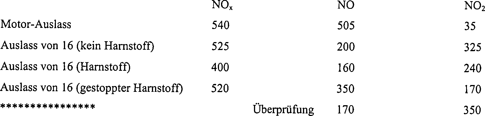
Daraus
geht hervor, dass die Injektion von Harnstoff den NOx-Gehalt
des Gases um nur etwa 25% gesenkt hat, wobei etwa 75% des aus dem
Harnstoff stammenden Ammoniaks für
die Verwendung stromabwärts von
dem Filter
Claims (19)
Applications Claiming Priority (5)
| Application Number | Priority Date | Filing Date | Title |
|---|---|---|---|
| GB9822083 | 1998-10-12 | ||
| GB9822083A GB9822083D0 (en) | 1998-10-12 | 1998-10-12 | Emission control |
| GB9917042A GB9917042D0 (en) | 1998-10-12 | 1999-07-21 | Emission control |
| GB9917042 | 1999-07-21 | ||
| PCT/GB1999/003281 WO2000021647A1 (en) | 1998-10-12 | 1999-10-04 | Process and apparatus for treating combustion exhaust gas |
Publications (2)
| Publication Number | Publication Date |
|---|---|
| DE69916312D1 DE69916312D1 (en) | 2004-05-13 |
| DE69916312T2 true DE69916312T2 (en) | 2005-03-17 |
Family
ID=26314487
Family Applications (1)
| Application Number | Title | Priority Date | Filing Date |
|---|---|---|---|
| DE69916312T Expired - Lifetime DE69916312T2 (en) | 1998-10-12 | 1999-10-04 | METHOD AND DEVICE FOR TREATING COMBUSTION GASES |
Country Status (7)
| Country | Link |
|---|---|
| US (1) | US6863874B1 (en) |
| EP (1) | EP1128895B1 (en) |
| JP (1) | JP2002539348A (en) |
| AT (1) | ATE263616T1 (en) |
| AU (1) | AU6111799A (en) |
| DE (1) | DE69916312T2 (en) |
| WO (1) | WO2000021647A1 (en) |
Cited By (2)
| Publication number | Priority date | Publication date | Assignee | Title |
|---|---|---|---|---|
| DE102008037156A1 (en) | 2008-08-08 | 2010-02-18 | Audi Ag | Method and device for purifying an exhaust gas stream of a lean-running internal combustion engine |
| DE102006008400B4 (en) * | 2006-02-21 | 2015-06-03 | Fev Gmbh | Direct injection, spark ignition internal combustion engine with SCR catalyst and method therefor |
Families Citing this family (88)
| Publication number | Priority date | Publication date | Assignee | Title |
|---|---|---|---|---|
| DE10020170C1 (en) * | 2000-04-25 | 2001-09-06 | Emitec Emissionstechnologie | Process for removing soot particles from the exhaust gas of internal combustion engine comprises feeding gas through collecting element, and holding and/or fluidizing until there is sufficient reaction with nitrogen dioxide in exhaust gas |
| GB9913331D0 (en) * | 1999-06-09 | 1999-08-11 | Johnson Matthey Plc | Treatment of exhaust gas |
| DE10020555A1 (en) * | 2000-04-27 | 2001-10-31 | Bosch Gmbh Robert | Method and device for cleaning exhaust gases from an internal combustion engine |
| DE10026696A1 (en) * | 2000-05-30 | 2001-12-20 | Emitec Emissionstechnologie | Particle trap |
| GB0013609D0 (en) * | 2000-06-06 | 2000-07-26 | Johnson Matthey Plc | Emission control |
| GB0013607D0 (en) * | 2000-06-06 | 2000-07-26 | Johnson Matthey Plc | Emission control |
| FI114731B (en) * | 2000-07-05 | 2004-12-15 | Kemira Metalkat Oy | Exhaust gas purification system and method |
| US20020007629A1 (en) * | 2000-07-21 | 2002-01-24 | Toyota Jidosha Kabushiki Kaisha | Device for purifying the exhaust gas of an internal combustion engine |
| US6826906B2 (en) | 2000-08-15 | 2004-12-07 | Engelhard Corporation | Exhaust system for enhanced reduction of nitrogen oxides and particulates from diesel engines |
| GB0021118D0 (en) * | 2000-08-29 | 2000-10-11 | Johnson Matthey Plc | Exhaust system for lean-burn engines |
| JP4251764B2 (en) * | 2000-09-08 | 2009-04-08 | 日産自動車株式会社 | Exhaust gas purification device and exhaust gas purification method using the same |
| US7021049B2 (en) * | 2000-09-29 | 2006-04-04 | Ford Global Technologies, Llc | Vehicle sulfur oxide trap and related method |
| DE10054877A1 (en) † | 2000-11-06 | 2002-05-29 | Omg Ag & Co Kg | Exhaust gas cleaning system for the selective catalytic reduction of nitrogen oxides under lean exhaust gas conditions and methods for exhaust gas cleaning |
| US7829033B2 (en) | 2003-07-03 | 2010-11-09 | Fuel Tech, Inc. | Selective catalytic reduction of NOx enabled by sidestream urea decomposition |
| GB0104682D0 (en) * | 2001-02-26 | 2001-04-11 | Johnson Matthey Plc | Gas treatment using ammonia |
| DE10113947B4 (en) * | 2001-03-22 | 2004-03-25 | Daimlerchrysler Ag | Process for reducing the nitrogen oxide content in the exhaust gas of a running in lean-fat change internal combustion engine |
| DE10128414A1 (en) * | 2001-06-12 | 2002-12-19 | Daimler Chrysler Ag | Exhaust gas system for cleaning internal combustion engine exhaust gases comprises a reducing agent supply having a hydrogen-producing unit for enriching the exhaust gas with hydrogen |
| GB0125890D0 (en) * | 2001-10-27 | 2001-12-19 | Johnson Matthey Plc | Exhaust system for an internal combustion engine |
| US7832203B2 (en) * | 2001-10-27 | 2010-11-16 | Johnson Matthey Public Limited Company | Exhaust system for a lean burn internal combustion engine |
| EP1458960B1 (en) | 2001-12-20 | 2011-02-09 | Johnson Matthey Public Limited Company | Improvements in selective catalytic reduction |
| DE10207986A1 (en) * | 2002-02-25 | 2003-09-04 | Daimler Chrysler Ag | Emission control system for an internal combustion engine |
| GB0220645D0 (en) | 2002-09-05 | 2002-10-16 | Johnson Matthey Plc | Exhaust system for a lean burn ic engine |
| DE10242303A1 (en) * | 2002-09-12 | 2004-03-18 | Robert Bosch Gmbh | Automotive diesel engine exhaust system has a soot particle filter module preceded by a NOx storage module |
| US7175821B2 (en) * | 2002-09-30 | 2007-02-13 | Tronox Llc | Reactor and process for reducing emissions of CO and NOx |
| JP2004138022A (en) * | 2002-10-21 | 2004-05-13 | Babcock Hitachi Kk | Method of and device for treating diesel exhaust gas |
| US7332135B2 (en) * | 2002-10-22 | 2008-02-19 | Ford Global Technologies, Llc | Catalyst system for the reduction of NOx and NH3 emissions |
| DE10254764A1 (en) * | 2002-11-22 | 2004-06-03 | Emitec Gesellschaft Für Emissionstechnologie Mbh | exhaust system |
| DE10300298A1 (en) * | 2003-01-02 | 2004-07-15 | Daimlerchrysler Ag | Exhaust gas aftertreatment device and method |
| DE10308287B4 (en) † | 2003-02-26 | 2006-11-30 | Umicore Ag & Co. Kg | Process for exhaust gas purification |
| GB0305415D0 (en) * | 2003-03-08 | 2003-04-16 | Johnson Matthey Plc | Exhaust system for lean burn IC engine including particulate filter and NOx absorbent |
| JP4052178B2 (en) * | 2003-05-15 | 2008-02-27 | 日産自動車株式会社 | Exhaust gas purification device for internal combustion engine |
| US7374735B2 (en) * | 2003-06-05 | 2008-05-20 | General Electric Company | Method for nitrogen oxide reduction in flue gas |
| GB0314245D0 (en) * | 2003-06-18 | 2003-07-23 | Johnson Matthey Plc | Engine exhaust gas treatment |
| DE602004006415T2 (en) | 2003-06-18 | 2008-01-10 | Johnson Matthey Public Ltd., Co. | PROCESS FOR CONTROLLING THE REDUCTION ADDITIVE |
| US20050047982A1 (en) * | 2003-08-29 | 2005-03-03 | Berriman Lester P. | Engine emissions nox reduction |
| US7490464B2 (en) * | 2003-11-04 | 2009-02-17 | Basf Catalysts Llc | Emissions treatment system with NSR and SCR catalysts |
| JP2008502843A (en) * | 2004-06-18 | 2008-01-31 | ジョンソン、マッセイ、パブリック、リミテッド、カンパニー | Reductant-added exhaust system with NOx absorbent |
| EP1812696B9 (en) * | 2004-10-11 | 2008-11-26 | Volvo Lastvagnar Ab | System and method for reduction of nitrogen oxides from exhaust gases generated by a lean-burn internal combustion engine |
| US20060168948A1 (en) * | 2005-02-02 | 2006-08-03 | Lifeng Xu | Alumina-based lean NOx trap system and method of use |
| US20060168949A1 (en) * | 2005-02-02 | 2006-08-03 | Lifeng Xu | Alumina-based lean NOx trap system and method of use in dual-mode HCCI engines |
| US20060179825A1 (en) * | 2005-02-16 | 2006-08-17 | Eaton Corporation | Integrated NOx and PM reduction devices for the treatment of emissions from internal combustion engines |
| DE102005013707A1 (en) * | 2005-03-24 | 2006-09-28 | Daimlerchrysler Ag | Motor vehicle with internal combustion engine and method for operating an internal combustion engine |
| US8327631B2 (en) * | 2005-03-28 | 2012-12-11 | Sal Caro | Air pollution control system for ocean-going vessels |
| US20060236680A1 (en) * | 2005-04-26 | 2006-10-26 | Wenzhong Zhang | Method for regenerating a diesel particulate filter |
| US8115373B2 (en) | 2005-07-06 | 2012-02-14 | Rochester Institute Of Technology | Self-regenerating particulate trap systems for emissions and methods thereof |
| US7251929B2 (en) * | 2005-07-07 | 2007-08-07 | Eaton Corporation | Thermal management of hybrid LNT/SCR aftertreatment during desulfation |
| US20070012032A1 (en) * | 2005-07-12 | 2007-01-18 | Eaton Corporation | Hybrid system comprising HC-SCR, NOx-trapping, and NH3-SCR for exhaust emission reduction |
| EP1943417A4 (en) * | 2005-09-12 | 2009-12-23 | Mcmaster Fuel Ltd | Internal combustion engine having on-board electrolyzer and method of using same |
| DE102005059451A1 (en) * | 2005-12-13 | 2007-06-21 | Volkswagen Ag | Method for reducing the NOx emission of diesel engines |
| US7862640B2 (en) | 2006-03-21 | 2011-01-04 | Donaldson Company, Inc. | Low temperature diesel particulate matter reduction system |
| JP4715581B2 (en) * | 2006-03-24 | 2011-07-06 | いすゞ自動車株式会社 | Exhaust gas purification system control method and exhaust gas purification system |
| JP5373255B2 (en) * | 2006-05-29 | 2013-12-18 | 株式会社キャタラー | NOx reduction catalyst, NOx reduction catalyst system, and NOx reduction method |
| US20080016850A1 (en) * | 2006-07-21 | 2008-01-24 | Eaton Corporation | Simultaneous LNT and DPF regeneration |
| US7726118B2 (en) * | 2006-09-18 | 2010-06-01 | Ford Global Technologies, Llc | Engine-off ammonia vapor management system and method |
| US7673446B2 (en) * | 2007-01-29 | 2010-03-09 | Caterpillar Inc. | Dual path exhaust emission control system |
| US20080196398A1 (en) * | 2007-02-20 | 2008-08-21 | Eaton Corporation | HC mitigation to reduce NOx spike |
| US7810315B2 (en) * | 2007-02-20 | 2010-10-12 | Eaton Corporation | LNT regeneration strategy to reduce NOx spike |
| JP2008223641A (en) * | 2007-03-13 | 2008-09-25 | Yamaha Motor Co Ltd | Exhaust emission control device for internal combustion engine |
| EP2156026B1 (en) * | 2007-05-15 | 2016-10-12 | Donaldson Company, Inc. | Exhaust gas flow device |
| JP4894615B2 (en) * | 2007-05-15 | 2012-03-14 | トヨタ自動車株式会社 | Exhaust gas purification device for internal combustion engine |
| US8176729B2 (en) * | 2008-03-06 | 2012-05-15 | GM Global Technology Operations LLC | Perturbation control strategy for low-temperature urea SCR NOx reduction |
| US8071037B2 (en) * | 2008-06-25 | 2011-12-06 | Cummins Filtration Ip, Inc. | Catalytic devices for converting urea to ammonia |
| GB2465151A (en) * | 2008-11-05 | 2010-05-12 | Agco Sa | Engine exhaust treatment unit |
| US8459012B2 (en) * | 2008-11-19 | 2013-06-11 | Caterpillar Inc. | Method for purging a dosing system |
| DE102008063488A1 (en) * | 2008-12-17 | 2010-06-24 | Emitec Gesellschaft Für Emissionstechnologie Mbh | Method and device for the drop-shaped addition of a liquid reducing agent in an exhaust pipe |
| WO2010078052A1 (en) * | 2008-12-17 | 2010-07-08 | Donaldson Company, Inc. | Flow device for an exhaust system |
| JP5429286B2 (en) * | 2009-06-03 | 2014-02-26 | トヨタ自動車株式会社 | Exhaust gas purification device for internal combustion engine |
| US20110002376A1 (en) * | 2009-07-01 | 2011-01-06 | Wham! Inc. | Latency Minimization Via Pipelining of Processing Blocks |
| US8371108B2 (en) * | 2009-07-29 | 2013-02-12 | Ford Global Technologies, Llc | Twin turbo diesel aftertreatment system |
| US8539761B2 (en) * | 2010-01-12 | 2013-09-24 | Donaldson Company, Inc. | Flow device for exhaust treatment system |
| EP2529091B1 (en) | 2010-01-25 | 2016-04-06 | Peugeot Citroën Automobiles SA | Exhaust gas aftertreatment device of an internal combustion engine |
| US8763369B2 (en) * | 2010-04-06 | 2014-07-01 | GM Global Technology Operations LLC | Apparatus and method for regenerating an exhaust filter |
| DE102010014468B4 (en) | 2010-04-09 | 2013-10-31 | Umicore Ag & Co. Kg | Process for the reduction of nitrous oxide in the exhaust aftertreatment of lean burn engines |
| US7914747B1 (en) * | 2010-04-23 | 2011-03-29 | General Electric Company | System and method for controlling and reducing NOx emissions |
| US9308496B2 (en) | 2010-04-23 | 2016-04-12 | General Electric Company | System and method for controlling and reducing NOx emissions |
| US9670811B2 (en) | 2010-06-22 | 2017-06-06 | Donaldson Company, Inc. | Dosing and mixing arrangement for use in exhaust aftertreatment |
| CN102908846A (en) * | 2011-08-05 | 2013-02-06 | 李启仁 | Flue gas environment-friendly purification and separation device |
| CN102512841A (en) * | 2012-01-04 | 2012-06-27 | 安庆五宁精细化工有限责任公司 | Absorption method for concentrated nitric acid diluting tail gas |
| US8938954B2 (en) | 2012-04-19 | 2015-01-27 | Donaldson Company, Inc. | Integrated exhaust treatment device having compact configuration |
| US9266092B2 (en) | 2013-01-24 | 2016-02-23 | Basf Corporation | Automotive catalyst composites having a two-metal layer |
| US9707525B2 (en) | 2013-02-15 | 2017-07-18 | Donaldson Company, Inc. | Dosing and mixing arrangement for use in exhaust aftertreatment |
| CN103537161B (en) * | 2013-11-04 | 2016-08-17 | 圣象实业(江苏)有限公司 | A kind of sealing wax line gas treatment equipment |
| CN103551003B (en) * | 2013-11-08 | 2015-09-09 | 中国恩菲工程技术有限公司 | Drip washing equipment |
| DE212015000170U1 (en) | 2014-06-30 | 2017-02-14 | Haldor Topsoe A/S | Exhaust after-treatment system for a diesel engine |
| KR101488198B1 (en) | 2014-12-26 | 2015-02-06 | 한국에너지기술연구원 | Multi-functional particulate filter and exhaust gas filtering device using this |
| DK178859B1 (en) * | 2015-07-09 | 2017-04-03 | Haldor Topsoe As | Method for the removal of particulate matter and noxious compounds from engine exhaust gas |
| CN110743287A (en) * | 2019-11-07 | 2020-02-04 | 深圳市比亚美塑胶模具有限公司 | Injection molding machine with exhaust treatment device |
| US11732628B1 (en) | 2020-08-12 | 2023-08-22 | Old World Industries, Llc | Diesel exhaust fluid |
Family Cites Families (20)
| Publication number | Priority date | Publication date | Assignee | Title |
|---|---|---|---|---|
| JPS62117620A (en) | 1985-11-19 | 1987-05-29 | Nippon Shokubai Kagaku Kogyo Co Ltd | Method for removing nitrogen oxide contained in exhaust gas of gasoline engine |
| US4902487A (en) | 1988-05-13 | 1990-02-20 | Johnson Matthey, Inc. | Treatment of diesel exhaust gases |
| JPH0559942A (en) * | 1991-08-29 | 1993-03-09 | Toyota Motor Corp | Cold hc adsorption removal device |
| JP2605586B2 (en) | 1992-07-24 | 1997-04-30 | トヨタ自動車株式会社 | Exhaust gas purification device for internal combustion engine |
| JP3311051B2 (en) * | 1992-12-16 | 2002-08-05 | 日本碍子株式会社 | Exhaust gas purification method and apparatus |
| US5406790A (en) | 1992-12-11 | 1995-04-18 | Toyota Jidosha Kabushiki Kaisha | Exhaust gas purification device for an engine |
| FR2699524B1 (en) * | 1992-12-21 | 1995-02-10 | Rhone Poulenc Chimie | Composition based on a mixed oxide of cerium and zirconium, preparation and use. |
| DE69427744T2 (en) | 1993-04-28 | 2002-05-23 | Nippon Catalytic Chem Ind | METHOD FOR REMOVING NITROGEN OXYDES CONTAINED IN EXHAUST GAS |
| EP0628706A2 (en) * | 1993-06-10 | 1994-12-14 | Inco Limited | Catalytic conversion of internal combustion engine exhaust gases |
| JP2984528B2 (en) * | 1993-10-04 | 1999-11-29 | トヨタ自動車株式会社 | Exhaust gas purification device for internal combustion engine |
| JP2937738B2 (en) * | 1994-04-05 | 1999-08-23 | 株式会社新潟鉄工所 | Reducing agent spraying equipment for flue gas denitration equipment |
| EP0839264B1 (en) * | 1994-09-13 | 1999-12-01 | Siemens Aktiengesellschaft | Process and device for introducing a fluid into an exhaust gas purification system |
| US5772972A (en) * | 1995-01-09 | 1998-06-30 | Ford Global Technologies, Inc. | Catalyst/hydrocarbon trap hybrid system |
| JP3899534B2 (en) * | 1995-08-14 | 2007-03-28 | トヨタ自動車株式会社 | Exhaust gas purification method for diesel engine |
| US5727385A (en) | 1995-12-08 | 1998-03-17 | Ford Global Technologies, Inc. | Lean-burn nox catalyst/nox trap system |
| JP3557815B2 (en) | 1996-11-01 | 2004-08-25 | トヨタ自動車株式会社 | Exhaust gas purification device for internal combustion engine |
| DE19653756C2 (en) * | 1996-12-20 | 1999-01-14 | Porsche Ag | New control strategy for a NOx storage |
| JP3645704B2 (en) * | 1997-03-04 | 2005-05-11 | トヨタ自動車株式会社 | Exhaust gas purification device for internal combustion engine |
| GB9801023D0 (en) * | 1998-01-19 | 1998-03-18 | Johnson Matthey Plc | Combatting air pollution |
| US6199375B1 (en) * | 1999-08-24 | 2001-03-13 | Ford Global Technologies, Inc. | Lean catalyst and particulate filter control system and method |
-
1999
- 1999-10-04 US US09/807,343 patent/US6863874B1/en not_active Expired - Lifetime
- 1999-10-04 DE DE69916312T patent/DE69916312T2/en not_active Expired - Lifetime
- 1999-10-04 AU AU61117/99A patent/AU6111799A/en not_active Abandoned
- 1999-10-04 JP JP2000575607A patent/JP2002539348A/en active Pending
- 1999-10-04 EP EP99947745A patent/EP1128895B1/en not_active Expired - Lifetime
- 1999-10-04 WO PCT/GB1999/003281 patent/WO2000021647A1/en active IP Right Grant
- 1999-10-04 AT AT99947745T patent/ATE263616T1/en not_active IP Right Cessation
Cited By (2)
| Publication number | Priority date | Publication date | Assignee | Title |
|---|---|---|---|---|
| DE102006008400B4 (en) * | 2006-02-21 | 2015-06-03 | Fev Gmbh | Direct injection, spark ignition internal combustion engine with SCR catalyst and method therefor |
| DE102008037156A1 (en) | 2008-08-08 | 2010-02-18 | Audi Ag | Method and device for purifying an exhaust gas stream of a lean-running internal combustion engine |
Also Published As
| Publication number | Publication date |
|---|---|
| US6863874B1 (en) | 2005-03-08 |
| EP1128895A1 (en) | 2001-09-05 |
| ATE263616T1 (en) | 2004-04-15 |
| JP2002539348A (en) | 2002-11-19 |
| AU6111799A (en) | 2000-05-01 |
| DE69916312D1 (en) | 2004-05-13 |
| EP1128895B1 (en) | 2004-04-07 |
| WO2000021647A1 (en) | 2000-04-20 |
Similar Documents
| Publication | Publication Date | Title |
|---|---|---|
| DE69916312T2 (en) | METHOD AND DEVICE FOR TREATING COMBUSTION GASES | |
| DE602004003354T2 (en) | A PARTICLE FILTER AND NOX-ABSORBER EXHAUST SYSTEM FOR INTERNAL COMBUSTION ENGINE WITH LUBRICANTS | |
| DE102010014468B4 (en) | Process for the reduction of nitrous oxide in the exhaust aftertreatment of lean burn engines | |
| DE102010010039B4 (en) | Exhaust gas treatment system with a four-way catalyst and a urea-SCR catalyst and method of using the same | |
| EP1961933B1 (en) | Catalytically activated diesel particulate filter with ammoniac blocking action | |
| DE102010023820B4 (en) | Exhaust gas treatment system for a diesel engine, method of using an exhaust treatment system, and diesel engine and exhaust treatment system | |
| DE602004006415T2 (en) | PROCESS FOR CONTROLLING THE REDUCTION ADDITIVE | |
| DE102010023819B4 (en) | Exhaust gas treatment system for a diesel engine Method of using it and diesel engine and exhaust gas treatment system | |
| DE102012222801B4 (en) | Exhaust system and use of a washcoat | |
| DE69612645T3 (en) | Method for exhaust gas detoxification of a diesel engine | |
| EP2123345B1 (en) | Device for cleaning diesel exhaust gases | |
| DE102012222804B4 (en) | Exhaust system with substrate monolith that includes an SCR catalytic converter | |
| DE60109300T2 (en) | METHOD AND DEVICE FOR REMOVING NITROGEN OXIDES IN THE EXHAUST OF AN INTERNAL COMBUSTION ENGINE | |
| DE60125530T2 (en) | DIESEL EXHAUST SYSTEM WITH NOx TRAP | |
| EP2322773B1 (en) | Method for cleaning combustion engine exhaust gases | |
| DE102010011404A1 (en) | Sulfur tolerant, perovskite supported catalysts | |
| DE102014105739A1 (en) | Filter substrate comprising a zoned catalyst washcoat | |
| DE102012222806A1 (en) | An exhaust system for a lean-burn internal combustion engine comprising a PGM component and an SCR catalyst | |
| DE102012006448B4 (en) | Method for use in connection with an exhaust aftertreatment system | |
| DE102012222807A1 (en) | Exhaust system for a lean-burn internal combustion engine comprising an SCR catalyst | |
| DE102008048854A1 (en) | Control strategy for a catalyst concept for exhaust aftertreatment with several nitrogen oxide storage catalysts | |
| EP3103979A1 (en) | Catalytic convertor for removing nitrogen oxides from the exhaust gas of diesel engines | |
| DE60120306T2 (en) | emission control system | |
| DE102010056223A1 (en) | Exhaust system for a vehicle engine with spark ignition | |
| DE112014000482T5 (en) | Exhaust gas purifying catalyst and method for producing the same |
Legal Events
| Date | Code | Title | Description |
|---|---|---|---|
| 8364 | No opposition during term of opposition | ||
| 8328 | Change in the person/name/address of the agent |
Representative=s name: KROHER, STROBEL RECHTS- UND PATENTANWAELTE, 80336 |
|
| 8328 | Change in the person/name/address of the agent |
Representative=s name: DR. SCHOEN & PARTNER, 80336 MUENCHEN |