DE69910607T2 - ROTATION internal combustion engine - Google Patents

ROTATION internal combustion engine Download PDF

Info

Publication number
DE69910607T2
DE69910607T2 DE69910607T DE69910607T DE69910607T2 DE 69910607 T2 DE69910607 T2 DE 69910607T2 DE 69910607 T DE69910607 T DE 69910607T DE 69910607 T DE69910607 T DE 69910607T DE 69910607 T2 DE69910607 T2 DE 69910607T2
Authority
DE
Germany
Prior art keywords
rotor
stator
machine according
combustion
chamber
Prior art date
Legal status (The legal status is an assumption and is not a legal conclusion. Google has not performed a legal analysis and makes no representation as to the accuracy of the status listed.)
Expired - Lifetime
Application number
DE69910607T
Other languages
German (de)
Other versions
DE69910607D1 (en
Inventor
Roland Grant Clophill Heap
Current Assignee (The listed assignees may be inaccurate. Google has not performed a legal analysis and makes no representation or warranty as to the accuracy of the list.)
HEAP, ROLAND GRANT, PAWLETT, SOMERSET, GB
Original Assignee
Roland Grant Clophill Heap
Priority date (The priority date is an assumption and is not a legal conclusion. Google has not performed a legal analysis and makes no representation as to the accuracy of the date listed.)
Filing date
Publication date
Application filed by Roland Grant Clophill Heap filed Critical Roland Grant Clophill Heap
Application granted granted Critical
Publication of DE69910607D1 publication Critical patent/DE69910607D1/en
Publication of DE69910607T2 publication Critical patent/DE69910607T2/en
Anticipated expiration legal-status Critical
Expired - Lifetime legal-status Critical Current

Links

Classifications

    • FMECHANICAL ENGINEERING; LIGHTING; HEATING; WEAPONS; BLASTING
    • F01MACHINES OR ENGINES IN GENERAL; ENGINE PLANTS IN GENERAL; STEAM ENGINES
    • F01DNON-POSITIVE DISPLACEMENT MACHINES OR ENGINES, e.g. STEAM TURBINES
    • F01D1/00Non-positive-displacement machines or engines, e.g. steam turbines
    • F01D1/34Non-positive-displacement machines or engines, e.g. steam turbines characterised by non-bladed rotor, e.g. with drilled holes
    • FMECHANICAL ENGINEERING; LIGHTING; HEATING; WEAPONS; BLASTING
    • F02COMBUSTION ENGINES; HOT-GAS OR COMBUSTION-PRODUCT ENGINE PLANTS
    • F02CGAS-TURBINE PLANTS; AIR INTAKES FOR JET-PROPULSION PLANTS; CONTROLLING FUEL SUPPLY IN AIR-BREATHING JET-PROPULSION PLANTS
    • F02C5/00Gas-turbine plants characterised by the working fluid being generated by intermittent combustion

Abstract

An engine is disclosed that incorporates components purely or predominantly rotational components. An engine including a rotor and a stator, in which a combustion chamber is defined in the stator and a fluid receiving chamber is defined in the rotor, in which combustion gas can expand from the combustion chamber into the receiving chamber, whereby momentum is transferred from the combustion gas to the rotor.

Description

Die vorliegende Erfindung bezieht sich auf einen MotorThe present invention relates on an engine

Die Erfindung bezieht sich insbesondere auf einen Verbrennungsmotor mit innerer oder äußerer Verbrennung, bei dem in erster Linie Drehkolben zum Einsatz kommen.The invention particularly relates to an internal or external combustion engine, in which Rotary pistons are used in the first place.

Der Großteil der heutigen Verbrennungsmotoren verwendet Hubkolben. Es wird jedoch anerkannt, dass das Vorhandensein von Hubkolben der maximalen Betriebsgeschwindigkeit eines Motors eine Grenze auferlegt. Hinzu kommt, dass der Bedarf für die Beschränkung der mit den Hubkolben assoziierten Kräfte die Verwendung von Bauteilen von erheblichem Gewicht erfordert. Aus diesem Grund wurde versucht, Motoren zu entwickeln, bei denen nur oder vorwiegend Drehkolben zum Einsatz kommen. Bis heute ist der erfolgreichste Rotationskolbenmotor der "Wankel"-Motor, der nach seinem deutschen Erfinder benannt wurde. Trotz ihrer Einfachheit hatte diese Einheit aus verschiedenen Gründen jedoch nur beschränkten kommerziellen Erfolg. Der wichtigste dieser Gründe ist sein Ruf, dass der Motor Abdichtprobleme hat, wonach dann niedriges Drehmoment bei niedriger Motorgeschwindigkeit, unzulängliche Kraftstoffnutzung und relative hohe Verschmutzungsraten folgen. Die Einheit erfordert zudem sorgfältige Wartung und ihre Betriebsgeschwindigkeit muss beschränkt werden, wenn ein Versagen der Dichtung vermieden werden soll. Hinzu kommt, dass der Kolben eines Wankel-Motors (zumindest ein Kolben der Art, wie er in der Praxis am häufigsten zum Einsatz kommt) einer nicht nur rotierenden Bewegung unterzogen wird; er oszilliere auch und dies führt zu Restvibration.The majority of today's internal combustion engines used lifting piston. However, it is recognized that the presence of reciprocating piston the maximum operating speed of a motor imposed a limit. In addition, the need for limiting the associated with the reciprocating forces the use of components of considerable weight. Because of this, it was tried To develop engines in which only or predominantly rotary pistons be used. To date, the most successful rotary piston engine the "Wankel" engine after his German inventor was named. Despite its simplicity However, for various reasons, this unit had only limited commercial appeal Success. The most important of these reasons his reputation is that the engine has sealing problems, then low Torque at low engine speed, inadequate Fuel use and relatively high pollution rates follow. The unit also requires careful maintenance and speed of operation must be limited be, if a failure of the seal should be avoided. in addition comes that the piston of a Wankel engine (at least one piston of the type, as he most often in practice is used) subjected to a not only rotating movement becomes; it also oscillates and this leads to residual vibration.

Zu anderen Rotationskolbemnotoren dieser Art gehören auch diejenigen, die in DE1601582, FR977740 und FRI 192930 beschrieben werden.To other rotary piston engines belong to this species also those described in DE1601582, FR977740 and FRI 192930 become.

Gasturbinenmotoren sind ebenfalls bekannt. Bei diesen Motoren beaufschlagt das sich ausdehnende Verbrennungsgas die Flügel eines Rotors und überträgt somit dem Rotor ein Drehmoment. Eine Gasturbine hat den Vorteil, dass ihr Rotor eine rein rotationale Bewegung durchläuft, und sie kann daher bei minimaler Vibration bei hoher Geschwindigkeit operieren. Derartige Motoren weisen jedoch normalerweise nur innerhalb relativ enger Motorgeschwindigkeitsbereiche eine effiziente Operation auf, wodurch sie in vielen Umständen ungeeignet sind, wobei hierzu das wichtigste Beispiel ein Motor für ein motorbetriebenes Straßenfahrzeug ist.Gas turbine engines are also known. In these engines, the expanding combustion gas acts the wings a rotor and thus transmits a torque to the rotor. A gas turbine has the advantage that Its rotor undergoes a purely rotational movement, and it can therefore contribute operate with minimal vibration at high speed. such However, engines are usually only within relatively narrower Motor speed ranges on an efficient operation, thereby they are inappropriate in many circumstances are the most important example of a motor for a motorized road vehicle is.

Ein Ziel der Erfindung besteht darin, einen Motor zu liefern, der vorwiegend Rotationsbauteile hat und einige der Nachteile der bekannten Motoren überwindet oder zumindest abschwächt.An object of the invention is to deliver an engine that has predominantly rotary components and some overcomes or at least mitigates the disadvantages of the known engines.

Als ersten Aspekt liefert die Erfindung einen Motor mit einer Verbrennungskonstruktion, bestehend aus einem Rotor und einem Stator, bei der eine Verbrennungskammer im Stator definiert ist, in der das Verbrennungsgas aus der Verbrennungskammer in eine Aufnahmekammer expandieren kann, wodurch Bewegungsenergie vom Verbrennungsgas auf den Rotor übertragen wird, wobei der Rotor eine Vielzahl von Ausdehnungskammern mit schrittweise ansteigenden Volumen hat. in die das Gas aus den Kammern des Rotors expandieren kann.As a first aspect, the invention provides an engine with a combustion construction consisting of a Rotor and a stator, where a combustion chamber in the stator is defined, in which the combustion gas from the combustion chamber can expand into a receiving chamber, generating kinetic energy is transferred from the combustion gas to the rotor, wherein the rotor a plurality of expansion chambers with gradually increasing Has volume. in which expand the gas from the chambers of the rotor can.

Ein solcher Motor kann ein Minimum von Bauteilen aufweisen, von denen keines einer Oszillation unterworfen wird.Such an engine can be a minimum of components, none of which is subject to oscillation becomes.

Die Verbrennungskammer hat vorzugsweise ein größeres Volumen als mehrere der Rotorausdehnungskammern.The combustion chamber preferably has a larger volume as more of the rotor expansion chambers.

In der bevorzugten Ausführung hat der Rotor eine Transferkammer, durch das Verbrennungsgas während eines Teils der Drehung des Rotors in die Verbrennungskammer strömen kann.In the preferred embodiment has the rotor a transfer chamber, through the combustion gas during a Part of the rotation of the rotor can flow into the combustion chamber.

Eine Motorausführung der Erfindung kann ein Funkzündgerät zusammen mit der Verbrennungskammer haben, um eine Ladung verbrennbarer Flüssigkeit, die in die Kammer geströmt ist, zu entzünden. Zum Funkzündgerät gehört typisch eine Zündkerze.An engine implementation of the invention may include Radio ignitor together with the combustion chamber to produce a charge of combustible liquid, who poured into the chamber is to kindle. The radio ignitor is typical a spark plug.

Bei einer Motorausführung der Erfindung können der Rotor oder der Stator oder beide aus einem Material hergestellt werden, das selbstschmierende Eigenschaften hat. So können z. B. entweder der Rotor oder der Stator aus rundlichem Graphiteisen gefertigt sein.In an engine version of the Invention can the rotor or the stator or both made of a material which has self-lubricating properties. So z. B. either the rotor or the stator of roundish graphite iron be made.

Als Alternative oder zusätzlich kann eine Motorausführung der Erfindung einen Ölnebelinjektor haben, der in einen Raum zwischen Rotor und Stator Ölnebel einspritzt. Dieser Ölnebel wird normalerweise in einer Position im Vorlauf der Verbrennungskammer injiziert.As an alternative or in addition can an engine version the invention an oil mist injector which injects oil mist into a space between rotor and stator. This oil mist is usually in a position in the forerun of the combustion chamber injected.

Eine Motorausführung der Erfindung kann zudem eine Schmierbürste aufweisen, die zwischen Stator und Rotor Schmiermittel, wie z. B. Graphit, hinzufügt.An engine version of the invention may also a lubricating brush have, between the stator and rotor lubricant such. B. Graphite, adds.

In einer Art von Motorausführung hat der Rotor Scheibenform und Kammern, die in sich zur Peripherie der Scheibe öffnen. Bei derartigen Ausführungen sollte der Motor vorzugsweise ein Abstandsreglersystem zur Steuerung der Trennung zwischen Rotor und Stator während des Motorbetriebs haben. Ein derartiges Abstandsreglersystem kann so operieren, dass es den Stator radial vom Rotor bewegt.In a kind of engine design has the rotor disc shape and chambers, which in to the periphery of the Open the disc. In such embodiments For example, the motor should preferably be a pitch controller system for control have the separation between rotor and stator during engine operation. Such a distance control system may operate to control the Stator moves radially from the rotor.

Bei derartigen Ausführungen kann der Rotor eine Rotoreihheit aufweisen, zu der ein Rotorgussstück gehört. Das Rotorgussstück kann Scheibenfom und peripherale Öffnung in darin gebildeten Hohlräumen haben. Die Rotoreinheit kann weiterhin Endplatten aufweisen, die am Rotorgusstück so montiert sind, dass sie diese Hohlräume axial schließen. Mehrere dieser Rotorgussstücke können zwischen den Endplatten montiert sein, um eine Verbrennungseinheit mit größerer Verbrennungskapazität zu liefern, wodurch sich eine praktische, modulare Konstruktionsform ergibt.In such embodiments, the rotor may have a rotor pitch, to which a rotor casting belongs. The rotor casting may have a disk shape and peripheral opening in cavities formed therein. The rotor assembly may further include end plates mounted on the rotor casting to axially close these cavities. Several of these rotor castings may be mounted between the end plates to provide a combustion unit with greater combustion capacity, thereby resulting in a practical results in a modular construction form.

Bei Ausführungen entsprechend des vorangegangenen Satzes kann ein Abstandsstück zwischen nebeneinander liegenden Rotorgussstücken angebracht werden, um die Wärmeableitung von der Verbrennungskammer zu und besonders von den Rotorgussstücken zu unterstützen. Das Abstandsstück kann typisch einen Durchlass aufweisen, der auf die Kühlflüssigkeitsleitungen der Rotorgussstücke ausgerichtet ist.For versions according to the previous Satzes can be a spacer between adjacent Rotorgussstücken be attached to the heat dissipation from the combustion chamber to and especially from the rotor castings too support. The spacer may typically have a passage on the coolant lines the rotor castings is aligned.

Die Statoreinheiten können ebenfalls eine Statoreinheit aufweisen, zu der ein Statorgussstück gehört. Das Statorgussstück kann so geformt sein, dass es die Rotoreinheit teilweise umgibt und Öffnungen in die darin gebildeten Hohlräume hat.The stator units can also a stator unit, to which a Statorgussstück belongs. The stator casting may be shaped to partially surround the rotor unit and openings in the cavities formed therein Has.

Die Statoreinheit kann zudem Endplatten aufweisen, die am Statorgussstück so angebracht sind, dass die diese Hohlräume axial schließen. Mehrere dieser Statorgussstücke können zwischen den Endplatten montiert sein, um eine Verbrennungseinheit mit größerer Verbrennungskapazität zu liefern.The stator unit can also end plates have, on the Statorgussstück are mounted so that close these cavities axially. Several these Statorgussstücke can be mounted between the end plates to a combustion unit to deliver with greater combustion capacity.

Bei Ausführungen entsprechend des vorangegangenen Satzes kann ein Abstandsstück zwischen nebeneinander liegenden Statorgussstücken angebracht werden, um die Wärmeableitung von der Verbrennungskammer zu und besonders von den Statorgussstücken zu unterstützen. Das Abstandsstück kann typisch Löcher aufweisen, die mit den Verbrennungskammern der verschiedenen Statorgussstücken in axialer Richtung verbunden sind. Als Alternative oder zusätzlich kann das Verbrennungsgemisch in jede der Verbrennungskammern eingeführt werden.For versions according to the previous Satzes can be a spacer be placed between adjacent Statorgussstücken to the heat dissipation from the combustion chamber to and especially from the Statorgussstücke to support. The spacer can be typical holes have with the combustion chambers of the various Statorgussstücken in Axial direction are connected. As an alternative or in addition can the combustion mixture is introduced into each of the combustion chambers.

Das optionale Rotor- und/oder Statorabstandsstück kann zur Wärmeableitung von hier Rippen haben.The optional rotor and / or stator spacer can for heat dissipation have ribs from here.

In einer anderen An der Ausführung des Motors hat der Rotur die Form eines Kegelstumpfs mit Kammern, die sich zu seiner Peripherie hin öffnen. Bei solchen Ausführungen umgibt der Stator normalerweise den Rotor. Bei diesen Ausführungen ist ein Abstandsreglersystem zur Steuerung eine Trennung zwischen dem Rotor und Stator währen des Motorbetriebs vorhanden. Ein derartiges Abstandsreglersystem kann so operieren, dass es den Stator axial zum Rotor bewegt.In another to the execution of the Motors, the rotur has the shape of a truncated cone with chambers, the open to its periphery. In such versions The stator normally surrounds the rotor. In these versions is a distance control system to control a separation between the rotor and stator of engine operation. Such a distance control system can operate so that it moves the stator axially to the rotor.

Bei Ausführungen mit einem Abstandsreglersystem kann ein kontaktloser Sensor zum Abstandsreglersystem gehören. Ein derartiger Sensor kann durch Kapayitätserfassung, induktives Erfassen oder eine Kombination von kapazitivem und induktivem Erfassen funktionieren.For versions with a distance control system For example, a contactless sensor may be part of the proximity controller system. On Such sensor can by Kapayitätserfassung, inductive sensing or a combination of capacitive and inductive detection work.

Bei einer weiteren An der Ausführung sind Stator und Rotor scheibenförmig, wobei die Verbrennungskammer zwischen den Flaschen Flächen des Rotors und des Stators definiert ist. Bei solchen Ausführungen operiert das Abstandsreglersystem so, dass es den Stator axial zum Rotor bewegt.In another on the execution are Stator and rotor disc-shaped, the combustion chamber between the bottles surfaces of the Rotor and the stator is defined. In such designs operated the distance control system so that it moves the stator axially to the rotor emotional.

Bei Ausführungen entsprechend eines der vorhergehenden Paragraphen können Rotor und/oder Stator ein Gusstück und eine oder mehrere Endplatten, wie oben beschrieben, aufweisen.For versions corresponding to one of the preceding paragraphs Rotor and / or stator a cast piece and one or more end plates as described above.

Eine Motorausführung der Erfindung kann zudem einen Kompressor zur Zuführung von Verbrennungsluft zur Verbrennungseinheit aufweisen. Der Kompressor kann vom Rotor angetrieben werden. Bei einer praktischen Konstruktion können Kompressor und Rotor auf einer gemeinsamen Welle oder auf miteinander verbundenen Koaxialwellen sitzen. Zwischen dem Kompressor und der Verbrennungseinheit sollte vorzugsweise eine Zwischenkühler vorhanden sein, der dazu dient die Wähne von der Verbrennungsluft abzuführen und somit die volumetrische Leistung des Motors verbessert.An engine version of the invention may also a compressor for feeding having combustion air to the combustion unit. The compressor can be driven by the rotor. In a practical design can Compressor and rotor on a common shaft or on interconnected Coaxial shafts sit. Between the compressor and the combustion unit should preferably be present an intercooler, the serves the wisdom remove from the combustion air and thus improving the volumetric performance of the engine.

Bei Ausführungen mit Funkenzündung kann der Kompressor Verbrernnungsluft mit einem Druck im Bereich von 4 bis 7 Bar liefern. Wo eine Kühlung der Verbrennungsluft stattfindet (z. B. in Form eines Zwischenkühlers), kann dieser Druck auf einen Bereich von 6 bis 12 Bar erhöht werden. Bei Kompressions-Zündungs-Ausführungen kann der Druck typisch im Bereich von 9 bis 15 Bar liegen. Wo eine Kühlung der Verbrennungsluft stattfindet (z. B. in Form eines Zwischenkühlers), kann dieser Druck auf einen Bereich von 20 bis 30 Bar erhöht werden.For versions with spark ignition can the compressor combustion air at a pressure in the range of 4 to 7 bar deliver. Where a cooling the combustion air takes place (eg in the form of an intercooler), This pressure can be increased to a range of 6 to 12 bar. For compression ignition versions The pressure can typically be in the range of 9 to 15 bar. Where one cooling the combustion air takes place (eg in the form of an intercooler), This pressure can be increased to a range of 20 to 30 bar.

Bei einigen Ausführungen wird der Brennstoff in einen Verbrennungsluftstrom außerhalb der Verbrennungseinheit injiziert. Als Alternative oder zusätzlich kann Brennstoff in eine Kammer innerhalb der Verbrennungseinheit eingespritzt werden.In some versions, the fuel is in a combustion air stream outside the combustion unit injected. As an alternative or in addition, fuel can be used in a Chamber be injected within the combustion unit.

Zusätzlich zu Brennstoff und Luft kann Wasser zusammen mit Luft und Brennstoff in die Verbrennungskammer eingeführt werden. Bei einigen derartigen Ausführung kann das Wasser während der Verbrennung als Dampf expandieren, wobei das Wasser verdampft und sich in die Aufnahmekammer ausdehnt und zumindest einen Teil seiner Bewegungsenergie auf den Rotor überträgt.In addition to fuel and air can water along with air and fuel into the combustion chamber introduced become. In some such embodiments, the water may during the Combustion as vapor expand, whereby the water evaporates and extends into the receiving chamber and at least part of his Transmitting kinetic energy to the rotor.

Anders gesehen liefert die Erfindung einen Verbrennungsmotor einschließlich eines Rotors und Stators, wobei der besagte Stator einen ersten Satz an Verbrennungskammern und der besagte Rotor einen zweiten Satz an Verbrennungskammern trägt und die Einheit so angeordnet ist, dass während des Betriebs der besagte Rotor relativ zum besagten Stator rotiert und ein Arbeitsmedium nacheinander zwischen den Verbrennungskammern der genannten ersten und zweiten Sätze übertragen wird und somit die Drehung des Rotors antreibt.In other words, the invention provides an internal combustion engine including a rotor and stator, said stator comprising a first set of combustion chambers and said rotor has a second set of combustion chambers wears and the unit is arranged so that during operation said Rotor rotates relative to said stator and a working medium successively between the combustion chambers of the first mentioned and second sentences and thus drives the rotation of the rotor.

Durch diese Anordnung kann der Motor mit Verbrennungskammern von optimaler Foren und Größe für einen bestimmten, geplanten Verwendungszweck ausgerüstet werden. Hinzu kommt, dass der Rotor typisch so angeordnet ist, dass seine Bewegung rein rotational und ohne Oszillation erfolgt.By this arrangement, the engine with combustion chambers of optimal forums and size for one certain intended use. In addition, that the rotor is typically arranged so that its movement is purely rotational and without oscillation.

Für den Erfolg dieses Motors ist ein neuer thermodynamischer Zyklus wichtig, der im 'heissen' Teil der Einheit zum Einsatz kommt. Der Motor kann entweder einen getrennten Einzel- oder Mehrstufenkompressor haben, um die Kompression des Arbeitsmediums, bei dem es sich normalerweise um Luft handelt, zu erzielen.For the success of this engine a new thermodynamic cycle is important, which in the 'hot' part of the Unit is used. The engine may have either a separate single or multi-stage compressor to achieve the compression of the working fluid, which is normally air.

Gemäß eines weiteren Aspekts der vorliegenden Erfindung ist ein Verbrennungsmotor einschließlich eines Rotors und eines Stators vorgesehen, wobei der besagte Stator einen ersten Satz an Verbrennungskammern und der besagte Rotor einen zweiten Satz an Verbrennungskammern trägt und die Einheit so angeordnet ist, dass während des Betriebs der besagte Rotor relativ zum besagten Stator rotiert und ein Arbeitsmedium nacheinander zwischen den Verbrennungskammern der genannten ersten und zweiten Sätze übertragen wird und somit die Drehung des Rotors antreibt.According to another aspect of the The present invention is an internal combustion engine including a Rotor and a stator provided, said stator a first set of combustion chambers and the said rotor a second Carries set of combustion chambers and the unit is arranged so that during operation said Rotor rotates relative to said stator and a working medium in succession between the combustion chambers of said first and second Transfer sentences and thus drives the rotation of the rotor.

Vorzugsweise werden eine oder mehrere Arten von Verbrennungskammern vorgesehen, einschließlich von einer oder mehreren Arten, auf die nachfolgend als 'Mutter-', 'Mädchen-' und 'Tochter-'Kammer Bezug genommen wird.Preferably, one or more Types of combustion chambers provided, including one or more species, referred to hereinafter as the 'mother', 'girl' and 'daughter' chambers.

Der Rotor und/oder der Stator weisen vorzugsweise einen Satz an Tochterkammern auf, deren Volumen schrittweise zunimmt.The rotor and / or the stator have preferably a set of daughter chambers, their volumes gradually increases.

Zumindest einige der Kammern sollten vorzugsweise Retortenform haben.At least some of the chambers should preferably have retort form.

Das Arbeitsmedium wird zwischen den Kammern vorzugsweise durch einen Prozess übertragen, der nachfolgend als "harmonische Gasfluktuierung" bezeichnet wird.The working medium is between the Preferably, chambers are transferred through a process, hereinafter as "harmonic Gas Fluctuation " becomes.

Der Motor sollte vorzugsweise einen Kompressor aufweisen, um der Verbrennungskammer ein Verbrennungsgemisch von Brennstoff und Luft zuzuführen.The engine should preferably have a Compressor to the combustion chamber a combustion mixture of fuel and air.

Entsprechend eines weiteren Aspekts der Erfindung ist ein Verbrennungsmotor einschließlich eines Rotors und eines Stators vorgesehen, wobei beim besagten Motor ein kadenzrekursiver Ausdehnungsprozess zum Antrieb der Rotorenrotation zum Einsatz kommt. Der kadenzrekursive Ausdehnungsprozess wird nachfolgend detaillierter beschrieben.According to another aspect The invention is an internal combustion engine including a rotor and a stator, wherein said motor is a cadence recursive Expansion process for driving the rotor rotation is used. The cadence recursive expansion process will become more detailed below described.

Eine Motorausführung dieser Erfindung kann verlässlich entwickelt werden und aufgrund der hohen Betriebsgeschwindigkeit des Motors und spezifischen Desigmnerkmalen Abdichtprobleme vermeiden. Er kann ohne Verschmutzung oder niedrige Drehmomente angelegt werden. Er kann zudem äußerst einfach angelegt sein und in seiner einfachsten Ausführung (zumindest theoretisch) lediglich einen Drehkolben haben. Hinzu kommt, dass eine Motorausführung der Erfindung eine hohe spezifische Leistungsabgabe bei niedrigem Gewicht liefern kann und somit ein spezifisches Leistungsgewicht haben kann, das dem der meisten effizienten Gasturbinen, die gegenwärtig erhältlich sind, entspricht. Die Leistung einer Motorausführung der Erfindung ist typisch hauptsächlich Wellen- und nicht Stoßkraft, wie bei einer Gasturbineneinheit. Der Motor kann sich daher für alle Antriebsapplikationen, angefangen von allen Arten von Straßentransports- bis hin zu allen Arten von Luftfahrtapplikationen, einschließlich von Hubschraubern und VTOL-Flugzeugen eignen. Er kann sich zudem für statische Krafterzeugung, gleichzeitige Energieerzeugung und Schiffahrtsapplikationen eignen: Aufgrund der Kombination von Drehung und des einzigartigen, angewandten thermodynamischen Zyklus kann er brennstoffeffizient und, aufgrund seines äußerst einfachen Prinzips, in der Herstellung kostengünstig sein.An engine version of this invention may reliable be developed and due to the high operating speed of the engine and specific design features avoid sealing problems. It can be applied without dirt or low torques. He can also be extremely simple be laid out and in its simplest form (at least theoretically) only have a rotary piston. In addition, an engine version of the Invention a high specific power output at low weight can deliver and thus have a specific power to weight ratio, that of the most efficient gas turbine currently available equivalent. The performance of an engine implementation of the invention is typical mainly Wave and not impact, like a gas turbine unit. The motor can therefore be used for all drive applications, from all types of road transport to all Types of aviation applications, including helicopters and VTOL aircraft are suitable. He may also be responsible for static power generation, simultaneous power generation and shipping applications are suitable: Due to the combination of rotation and the unique, applied thermodynamic cycle, it can be fuel efficient and, due his extremely simple Principle to be cost-effective to manufacture.

Während dieser Beschreibung werden immer Vergleiche mit vergleichbaren Hubkolbendesigns gezogen, um die erörtern Punkte zu illustrieren.While This description always compares with comparable reciprocating piston designs pulled to discuss the To illustrate points.

Es folgt nun eine detaillierte Beschreibung einer Ausführung der Erfindung, wobei auf die beiliegenden Zeichnungen Bezug genommen wird, wobei diese folgende sind:Here is a detailed description an execution of the invention, reference being made to the accompanying drawings which are the following:

1 ist eine Schnittübersichtszeichnung einer Funkzündungsmotorausführung der Erfindung; 1 Fig. 3 is a sectional overview drawing of a spark ignition engine embodiment of the invention;

1a ist ein schematischer Axialschnitt eines Kompressors des Motors von 1; 1a is a schematic axial section of a compressor of the engine of 1 ;

2a und 2b sind jeweils Höhen- und Planquerschnitte eines Kempressorrotors der Ausführung von 1; 2a and 2 B are each height and plan cross-sections of a Kempressorrotors the execution of 1 ;

3a und 3b sind jeweils Vorder- und Teilschnittseitenansichten einer modifizierten Kompressorrotorengehäuseeinheit; 3a and 3b FIG. 15 are front and partial sectional side views, respectively, of a modified compressor rotor housing unit; FIG.

4 ist eine perspektorische Ansicht eines Bauteils der Rotorengehäuseinheit von 3a und 3b; 4 is a perspective view of a component of the rotor housing unit of 3a and 3b ;

5, 6 sind Axial- und Planquerschnitte eines Zwischenkühlers, der Teil des Motors von 1 ist; 5 . 6 are Axial- and plan cross-sections of an intercooler, the part of the engine of 1 is;

7 ist ein Teilschnitt eines Rotors und eines Stators einer Verbrennungseinheit des Motors von 1 und zeigt ihre gegenseitige Beziehung; 7 is a partial section of a rotor and a stator of a combustion unit of the engine of 1 and shows their mutual relationship;

8 und 8a sind perspektivische und Axialansichten eines Rotorgussstücks des Motors von 1; 8th and 8a are perspective and axial views of a rotor casting of the engine of 1 ;

9 zeigt eine Endplatte für das Rotorgussstück von 8; 9 shows an end plate for the rotor casting of 8th ;

10 und 10a sind perspektivische und Axialansichten eines Statorgussstücks des Motors von 1; 10 and 10a are perspective and axial views of a Statorgussstücks the engine of 1 ;

11 ist eine Endplatte für das Statorgussstück von 10; 11 is an end plate for the Statorgussstück of 10 ;

12 und 12a sind schematische Querschnitte eines Teils des Rotors und des Stators von 2 während eines Verbrennungszyklus, wobei 12a ein Schnitt entlang der Linie A-A' von 7 ist; 13 ist ein Schnitt entlang Linie A-A auf 12a; 12 and 12a are schematic cross sections of a part of the rotor and the stator of 2 during a combustion cycle, wherein 12a a section along the line AA 'of 7 is; 13 is a section along line AA 12a ;

14a ist eine erste Auspuffkonfiguration, die sich zur Verwendung des Motors von 1 eignet; 14a is a first exhaust configuration dedicated to using the engine 1 suitable;

14b ist eine alternative Auspuffkonfiguration, die sich zur Verwendung des Motors von 1 eignet; 14b is an alternative exhaust configuration dedicated to using the engine 1 suitable;

15 ist ein Schaltplan für ein Feststellungssystem für Motorfehlzündungen, das sich zur Verwendung mit dem Motor von 1 eignet; 15 is a circuit diagram for a motor misfire detection system suitable for use with the engine of 1 suitable;

16 zeigt eine Schmierbürste, die sich zur Verwendung mit dem Motor von Abbildung eignet; 16 shows a lubricating brush that is suitable for use with the motor of Figure;

17 und 18 zeigen, schematisch, die relative Bewegung des Stators und des Rotors des Motors von 1; 17 and 18 show, schematically, the relative movement of the stator and the rotor of the motor of 1 ;

19 und 20 sind Querschnitte einer alternativen Ausführung der Erfindung; 19 and 20 are cross sections of an alternative embodiment of the invention;

21 ist ein Querschnitteiner weiteren alternativen Ausführung der Erfindung; 21 Figure 12 is a cross-section of another alternative embodiment of the invention;

22 bis 24 zeigen alternative Anordnungen für die Erhaltung eines geregelten Rotor-/Stator-Abstands; 22 to 24 show alternative arrangements for maintaining a controlled rotor / stator spacing;

25 zeigt eine Anordnung zur Erhaltung eines geregelten Rotor-/Stator-Abstands und Überwachung des Lagerstatus; 25 shows an arrangement for maintaining a controlled rotor / stator distance and monitoring the storage status;

26 zeigt ein kontaktloses Abstandsreglersystem unter Inkorporation einer Kondensatorplatte als Sensor; 26 shows a contactless distance control system incorporating a capacitor plate as a sensor;

27 ist ein Diagramm für zusätzliche Schaltkreise zum Einsatz bei einem kombinierte Abstandsregler-, Lager- und Fehlzündungsüberwachungssystem mit Injektions- und Zündeinstellung; 27 Figure 12 is a diagram for additional circuitry for use with a combined autoclip, bearing and misfire monitoring system with injection and ignition timing;

28 zeigt Details im Querschnitt von einem Kompressor, der sich z. B. zum Einsatz beim Motor von 1 eignet; 28 shows details in cross-section of a compressor, the z. B. for use in the engine of 1 suitable;

29 zeigt einen Höhenschnitt eines Laufrads, das sich zur Verwendung im Kompressor von 28 eignet; 29 shows a vertical section of an impeller suitable for use in the compressor of 28 suitable;

30 ist ein Schnitt entlang Linie A-A' von 29; 30 is a section along line AA 'of 29 ;

31 zeigt ein Gehäuse als Bestandteil des Kompressors von 28; 31 shows a housing as part of the compressor of 28 ;

32 und 32a zeigen Höhen- und Querschnitte eines Diffuserrings des Kompressors von 28; 32 and 32a show height and cross sections of a diffuser ring of the compressor of 28 ;

33 ist ein Diagramm für ein System zur Messung und Kontrollen von Temperaturen von Bauteilen einer Motorausführung der Erfindung; 33 FIG. 10 is a diagram for a system for measuring and controlling temperatures of engine-mounted components of the invention; FIG.

34 bis 44 zeigen, im Längs- und Planschnitt, verschiedene alterative Konfigurationen von Motoren als Ausführungen der Erfindung; 34 to 44 show, in longitudinal and plan section, various alternative configurations of engines as embodiments of the invention;

45 bis 57 sind verschiedene alternative, externe Konfigurationen von Motoren als Ausführungen der Erfindung; 45 to 57 are various alternative external configurations of engines as embodiments of the invention;

58a bis 58f sind schematische Querschnitte von teilen einer Motorausführung der Erfindung; 58a to 58f Fig. 3 are schematic cross sections of parts of an engine embodiment of the invention;

59 und 60 zeigen detaillierte Designmerkmale von Ausdehnungskammern bei einer Motorausführung der Erfindung; 59 and 60 show detailed design features of expansion chambers in an engine embodiment of the invention;

61 zeigt schematisch einen Kompressor mit Einlass- und Auslassreglerventilen und 61 schematically shows a compressor with inlet and outlet control valves and

52 zeigt schematisch einen Kompressor einschließlich von mehrfachen (optional modularen) Einheiten mit Auslassreglerventilen. 52 schematically shows a compressor including multiple (optionally modular) units with outlet control valves.

Allgemeine KonfigurationGeneral configuration

Mit bezug auf zunächst 1 weist eine Motorausführung der Erfindung einen Gaströmungsweg allgemein von rechts nach links auf 1 auf. Die Verbrennungsluft strömt am Einlass 100 in den Motor und geht dann in einen Kompressor 100. Von dort strömt sie zu einem Zwischenkühler 112, von wo aus sie durch eine Leitung 114 in eine Verbrennungseinheit 116 strömt. Abluftgase verlassen dann die Verbrennungseinheit 116 (die auch als 'heisser Bereich' bezeichnet wird) und strömen zu einer Abgasturbine 118, von wo aus sie dann in die Atmosphäre entlüftet werden. Ein Kühlungsluftstrom fließt ebenfalls durch den Zwischenkühler 112, die Verbrennungseinheit 116 und dann in die Turbine 118. Jeder dieser Motorbauteile ist um eine Welle 122 konstruiert, die zur Rotation um eine Motorachse A auf Lagern sitzt. Bei dieser Ausführung sitzt ein Gebläse 120 auf der Welle zwischen dem Zwischenkühler 112 und der Verbrennungseinheit 116, um die Kühlungsluft durch den Motor zu treiben. Aus praktischen Gründen wird die Einlassleitung 100 in Richtung "Einlassende" des Motors liegend beschrieben und die Turbine wird als in Richtung des "Auslassendes" des Motors liegend beschrieben.With reference to first 1 For example, an engine implementation of the invention includes a gas flow path generally from right to left 1 on. The combustion air flows at the inlet 100 in the engine and then goes into a compressor 100 , From there it flows to an intercooler 112 from where they pass through a line 114 in a combustion unit 116 flows. Exhaust gases then leave the combustion unit 116 (which is also referred to as a 'hot area') and flow to an exhaust gas turbine 118 from where they are then vented to the atmosphere. A cooling air flow also flows through the intercooler 112 , the combustion unit 116 and then into the turbine 118 , Each of these engine components is around a shaft 122 designed to sit on a bearing for rotation about a motor axis A. This version has a fan 120 on the shaft between the intercooler 112 and the combustion unit 116 to drive the cooling air through the engine. For practical reasons, the inlet pipe 100 in the direction of the "inlet end" of the engine and the turbine is described as lying in the direction of the "exhaust end" of the engine.

Die Konstruktion und Funktion jeder dieser Motorbauteile wird nachfolgend detaillierter beschrieben.The construction and function of each This engine components will be described in more detail below.

Luftansaugung und VerdichtungAir intake and compression

Verbrennungsluft wird außerhalb der Verbrennungskammer verdichtet. Dies ist anders als bei einem typischen Kolbenverbrennungsmotor, wo die Verdichtung in einer Verbrennungskammer durch einen Kolben stattfindet; bei dieser Ausführung erfolgt die Verdichtung durch einen Mehrstufen-Turboverdichter 110.Combustion air is compressed outside the combustion chamber. This is unlike a typical reciprocating internal combustion engine where compression in a combustion chamber occurs through a piston; In this embodiment, the compression takes place by a multi-stage turbo compressor 110 ,

Der Kompressor weist einen ersten und zweiten Rotor 124, 126 auf, die jeweils auf der Welle 122 sitzen und oder zur Rotation mit dieser befestigt sind. 2a und 2b zeigen einen Rotor. Jeder Rotor hat eine allgemein ringförmige Spannplatte 128, die auf einer Bosse 132 sitzt, die an der Welle 122 so befestigt ist, dass sich die Spannplatte allgemein bis zur Motorachse A ausdehnt.The compressor has first and second rotors 124 . 126 on, each on the shaft 122 sit and or are fixed for rotation with this. 2a and 2 B show a rotor. Each rotor has a generally annular clamping plate 128 on a boss 132 sitting at the shaft 122 is fastened so that the clamping plate expands generally to the motor axis A.

Eine Vielzahl an Flügeln 130, 130' stehen von der Spannplatte 128 vor, allgemein in Richtung des Motoreinlass. Bei dieser Ausführung gibt es insgesamt zweiunddreißig Flügel, wobei die Flügel abwechselnd 130 lang und 130' kurz sind 2b zeigt die Anordnung mehrerer Flügel, wobei diese Anordnung sich in gleichen Abständen um den Rotor wiederholt. Die langen Flügel 130 reichen von der Nähe der Bosse bis zur Peripherie des Spannplatte 128, während die kürzeren Flügel 130' von ca.A variety of wings 130 . 130 ' stand from the clamping plate 128 in front, generally in the direction of the engine intake. In this design, there are a total of thirty-two wings, the wings alternately 130 long and 130 ' are short 2 B shows the arrangement of several wings, this arrangement is repeated at equal intervals around the rotor. The long wings 130 range from near the bosses to the periphery of the chuck plate 128 while the shorter wings 130 ' from approx.

Dreiviertel des Radius der Spannplatte nach außen zur Peripherie der Spannplatte reichen. Jeder Flügel 130, 130' ist so gebogen, dass die äußere Extremität des Flügels 130, 130' hinter der inneren Extremität des Flügels liegt, wenn sich die Welle in Richtung des normalen Motorbetriebs dreht.Three quarters of the radius of the clamping plate to the outside to the periphery of the clamping plate rich. Every wing 130 . 130 ' is bent so that the outer extremity of the wing 130 . 130 ' is behind the inner extremity of the wing when the shaft is turning in the direction of normal engine operation.

Die genaue Biegung und Zahl der Flügel ist in jedem Rotor 124, 126 optimiert, wobei sie gewählt wird, um deesen Leistungskraft bei der geplanten typischen Betriebsgeschwindigkeit für einen bestimmten Motor zu optimieren. Die Methodologien, durch die eine derartige Optimierung erzielt werden kann, sind den Fachleuten für Kompressordesign wohlbekanntThe exact bend and number of wings is in each rotor 124 . 126 It is optimized to optimize performance at the planned typical operating speed for a particular engine. The methodologies by which such optimization can be achieved are well known to those skilled in compressor design

Jeder Abschnitt des Kompressors 110 besteht zudem aus einem Gehäuse, in dem die Rotoren 124, 126 enthalten sind. Am Einlassende weist das Gehäuse eine ringfönnige Außenwand 134 auf, die eine Öffnung in der Mitte hat, welche die Welle 122 umgibt, wobei diese Öffnung in etwa den Durchmesser der inneren Flügelenden des ersten Rotors 124 aufweist. Bei dieser Offnung handelt es sich um den Einlass 100. Die Außenwand 134 liegt parallel zur Spannplatte 128 des ersten Rotors 124, und hat Abstand von den Flügeln 130, 130'.Every section of the compressor 110 It also consists of a housing in which the rotors 124 . 126 are included. At the inlet end, the housing has a ring-shaped outer wall 134 which has an opening in the middle, which is the shaft 122 surrounds, this opening approximately the diameter of the inner wing ends of the first rotor 124 having. This opening is the inlet 100 , The outer wall 134 lies parallel to the clamping plate 128 of the first rotor 124 , and is spaced from the wings 130 . 130 ' ,

Das Gehäuse weist weiterhin eine ringförmige Trennwand 136, die zwischen den beiden Rotoren 124, 126 verläuft. Eine Öffnung in der Mitte der Trennwand umgibt die Welle 122.The housing further has an annular partition 136 between the two rotors 124 . 126 runs. An opening in the middle of the partition surrounds the shaft 122 ,

Eine Innenwand 138 des Gehäuses befindet sich am Auslassende des Gehäuses. Die Innenwand umgibt die Welle eng und eine Flüssigkeitsdichte Dichtung befindet sich zwischen der Innenwand 138 und der Welle 122.An interior wall 138 The housing is located at the outlet end of the housing. The inner wall closely surrounds the shaft and a fluid-tight seal is located between the inner wall 138 and the wave 122 ,

Die Außenwand 134 und die Trennwand 136 sind um ihre Peripherie durch einen gebogenen Wandabschnitt 140 verbunden, deren Innenflächen konkav sind. Dies wird als "Ausströmraum" bezeichnet. Die Trennwand 136 und die Innenwand 138 sind gleichermaßen verbunden.The outer wall 134 and the partition 136 are around their periphery by a curved wall section 140 connected, whose inner surfaces are concave. This is called "outflow space". The partition 136 and the inner wall 138 are equally connected.

Wenn sich die Welle dreht, dann drehen sich die Rotoren 124, 126 mit. Die Flügel des ersten Rotors 124 treiben die Luft radial nach außen und saugen Luft durch den Einlass 100 herein. Die Luft, die vom ersten Rotor herausgetrieben wird, trifft auf den gebogenen Wandabschnitt auf und wird dann radial nach innen zwischen die Spannplatte des ersten Rotors und die Trennwand 136 getrieben. Von dort wird die Luft durch die Öffnung in der Zwischenwand gesogen, von wo aus sie wiederum durch den zweiten Rotor 126 radial nach außen getrieben wird.When the shaft rotates, the rotors rotate 124 . 126 With. The wings of the first rotor 124 drive the air radially outward and suck air through the inlet 100 in. The air expelled from the first rotor impinges on the curved wall portion and then becomes radially inward between the clamping plate of the first rotor and the dividing wall 136 driven. From there, the air is sucked through the opening in the intermediate wall, from where it in turn through the second rotor 126 is driven radially outward.

Ein solcher Kompressor 100 hat, als zweiteiliger radialer Kompressor, bei dieser Ausfürung einen Ausgabedruck von ca. 9,2 Bar.Such a compressor 100 has, as a two-piece radial compressor, in this Ausfürung an output pressure of about 9.2 bar.

In Bezug auf den Kompressor können bei der Konstruktion anderer Ausführungen zusätzliche Designerwägungen herangezogen werden. Es ist allgemein verstanden, dass der Luftstrom, den der Kompressor 110 erzeugen soll, von der Rate abhängt, bei der der Brennstoff in der Verbrennungseinheit verbraucht wird. Um diese Anforderung zu erfüllen, kann das Kompressorgehäuse aus einer Vielfalt an Modulen konstruiert werden, wobei jedes Modul jeweils einen Rotor enthält. Somit können zusätzliche Module nach Bedarf zur Verfügung gestellt werden, um einen ausreichenden Luftdurchsatz für die Verbrennung des Brennstoffs in der Verbrennungseinheit 116 zu erzeugen.With regard to the compressor, additional design considerations may be used in the construction of other designs. It is generally understood that the air flow that the compressor 110 depends on the rate at which the fuel is consumed in the combustion unit. To meet this requirement, the compressor housing can be constructed from a variety of modules, each module containing a rotor. Thus, additional modules may be provided as needed to provide sufficient air flow rate for combustion of the fuel in the combustion unit 116 to create.

Während ein Motor bei teilweiser oder niedriger Leistung operiert, ist die Luftmenge, die zur Unterstützung einer vollen Verbrennung zur Verfügung stehen muss, weniger als dies der Fall ist, wenn der Motor bei Volleistung operiert. Dies kann bei teilweiser Leistung zu Ineffizienz führen, insofern der Kompressor 100 mehr Kraft verbraucht, als gewöhnlich notwendig ist, um genügend Verbrennungsluft zu liefern Daher ist eine Modifikation, die am Kompressor vorgenommen werden könnte, die, dass die Luftmenge, die bei Teilleistung in den Kompressor eintreten oder aus diesem austreten kann, reduziert wird (wodurch der Luftwiderstand reduziert wird).While an engine operates at partial or low power, the amount of air that must be available to support full combustion is less than is the case when the engine is operating at full power. This can lead to inefficiency at partial performance, in that respect the compressor 100 Therefore, a modification that could be made to the compressor is that the amount of air that can enter or leave the compressor at partial power is reduced (which causes the compressor to lose power) Air resistance is reduced).

So findet sich z. B. auf 1a eine schematische Darstellung einer möglichen Konfiguration des Ausströmraums eines Kompressors. Der Ausströmraum hat, in diesem Fall vier, ähnliche Unterteilungen, die jeweils im Radius von der Achse A in Richtung der Rotorrotation 124 zunehmen, wobei die Teilabschnitte durch einen radialen Wandabschnitt 170 miteinander verbunden sind. An jedem radialen Wandabschnitt befindet sich ein Auslass 174 für Luft, die innerhalb des Kompressorgehäuses verdichtet wurde. Bei diesem Beispiel ist eine Durchführung 174 immer offen, um eine Zufuhr von Druckluft zur Verfügung zu stellen, während die anderen Auslässe 174 jeweils ein Ventil 176 aufweisen, das selektiv operiert werden kann, um eine Ausströmen in den jeweiligen Auslass 174 zu verhindern. Die Ventile 176 können individuell operiert werden oder mehrere können miteinander verbunden werden, um gemeinsam zu operieren.So you will find z. B. on 1a a schematic representation of a possible configuration of the discharge space of a compressor. The outflow space, in this case four, has similar subdivisions, each in radius from axis A in the direction of rotor rotation 124 increase, wherein the sections through a radial wall section 170 connected to each other. At each radial wall section is an outlet 174 for air that has been compressed inside the compressor housing. This example is an implementation 174 always open to provide a supply of compressed air while the other outlets 174 one valve each 176 which can be selectively operated to escape into the respective outlet 174 to prevent. The valves 176 can be operated on individually or several can be interconnected to operate together.

Mit Bezug auf die 3a, 3b und 4 ist eine Implementierung des Vorhabens möglich, wobei ein Luftzufuhrweg zu einigen der Flügel eines Kompressorrotors gegen das Eindringen von Luft verdeckt wird. Bei dieser alternativen Ausführung hat das Gehäuse 1140 einen Ring 1112, der auf einer lotrechten Ebene zur Motorenachse A liegt, den Einlass 1144 umgibt und einen solchen Durchmesser hat, dass er sich nahe an den inneren Enden der Flügel 1130 befindet. Der Ring 1112 hat eine Vielzahl an Verschlussklappen 1110. Jede Klappe 1110 ist als dünne Platte gestaltet und gerundet, damit sie einem Bogen, der sich um die Motorachse A zentriert, folgt. In der Nähe eines Endes (der größeren Kante der Klappe, die man bei normaler Drehbewegung des Motors antrifft) ist die Klappe 1110 am Ring 1112 so befestigt, dass sie sich um eine Achse drehen kann, die parallel zur Motorachse A und neben dem runden Bereich liegt, an dem die Enden der langen Flügel 1130 liegen, liegt. An einem Extrem ihrer Drehbewegung erstreckt sich die Klappe 1110 vom besagten Bereich zu einem Endbereich einer Klappe 1110 und schließt somit mehr oder weniger die tuftlücke zwischen nebeneinander liegenden Klappen 1110 zu den Flügeln 1130. Am anderen Extrem ihrer Drehbewegung projektiert die Klappe 1110 nach innen vom Rundbereich und öffnet somit die Luftlücke. Bei einer idealen Anordnung erstrecken sich die Klappen fortlaufend für ca. Dreiviertel der Peripherie des Rings 1112.With reference to the 3a . 3b and 4 an implementation of the project is possible, wherein an air supply path to some of the blades of a compressor rotor is obscured against the ingress of air. In this alternative embodiment, the housing has 1140 a ring 1112 located on a vertical plane to the engine axis A, the inlet 1144 surrounds and has such a diameter that it is close to the in neren ends of the wings 1130 located. The ring 1112 has a variety of flaps 1110 , Every flap 1110 is designed as a thin plate and rounded to follow an arc centered around the motor axis A. Near one end (the larger edge of the flap encountered in normal rotary motion of the engine) is the flap 1110 on the ring 1112 fixed so that it can rotate about an axis which is parallel to the motor axis A and adjacent to the circular area at which the ends of the long wings 1130 lie, lies. At one extreme of its rotation, the flap extends 1110 from said area to an end region of a flap 1110 and thus more or less closes the tuft gap between adjacent flaps 1110 to the wings 1130 , At the other extreme of its rotation projected the flap 1110 inward from the round area and thus opens the air gap. In an ideal arrangement, the flaps extend continuously for approximately three quarters of the circumference of the ring 1112 ,

Die Bewegung der Klappen 1110 wird durch einen Mechanismus kontrolliert, der am deutlichsten auf 4 dargestellt ist. Jede Klappe hat einen Zapfen, der sich durch den Ring 1112 erstreckt, und ein Kurbelhebel 1114 wird auf dem Zapfen daneben zur gegenüberliegenden Seite des Rings 1112 getragen. Ein Solenoidstellglied 1116 ist mit dem Kurbelhebel 1114 über eine Verbindungsstange 1120 verbunden. Am Solenoidstellglied 1116 kann elektrischer Strom angelegt werden, um die Verbindungsstange 1120 linear anzutreiben, wobei diese lineare Bewegung wiederum eine Drehbewegung der assoziierten Klappe 1120 zwischen ihren Bewegungsextremen bewirkt. Eine Feder ist vorgesehen, um die Verbindungsstange 1120 in die Position zu bringen, in der die Klappe 1110 ganz geöffnet ist, wobei es sich hierbei um eine Fail-Safe-Position handelt, bei der der Motor bei Stromausfall zu den Stellgliedern 1116 weiterläuft.The movement of the flaps 1110 is controlled by a mechanism that is most evident 4 is shown. Each flap has a pin that extends through the ring 1112 extends, and a crank lever 1114 is on the pin next to the opposite side of the ring 1112 carried. A solenoid actuator 1116 is with the crank lever 1114 over a connecting rod 1120 connected. At the solenoid actuator 1116 Electric current can be applied to the connecting rod 1120 to drive linearly, this linear movement in turn a rotational movement of the associated flap 1120 between their extremes of movement. A spring is provided around the connecting rod 1120 to bring in the position in which the flap 1110 is fully open, which is a fail-safe position, in which the motor in case of power failure to the actuators 1116 continues.

Die verschiedenen Stellglieder 1116 werden durch eine Steuereinheit kontrolliert, um sich entsprechend der unterschiedlichen Anforderungen der Verbrennungseinheit 116 nach Verbrennungsluft zu öffnen und zu schließen. Eine Methode zu Kontrolle der Ansaugung von Verbrennungsluft wird nachfolgend im Detail beschrieben.The different actuators 1116 are controlled by a control unit to conform to the different requirements of the combustion unit 116 to open and close combustion air. A method of controlling the intake of combustion air will be described in detail below.

Diese Anordnung eignet sich möglicherweise besser für eine Applikation zur Kontrolle des Luftstroms zum ersten Rotor 124, wo am Einlass 100 mehr Platz zur Verfügung steht, da eine Öffnung in der Trennwand vorhanden ist.This arrangement may be better suited for an application to control the flow of air to the first rotor 124 where at the inlet 100 more space is available because there is an opening in the partition wall.

KühlungsluftstromCooling air flow

Das Gebläse 120 ist so montiert, dass es mit der Welle 122 rotiert. Das Gebläse 120 soll dafür sorgen, dass ein Luftstrom axial durch den Motor strömt, um verschiedene Motorteile zu kühlen. Die Kühlungsluft strömt insbesondere durch den Zwischenkühler 112 und durch die Verbrennungseinheit 116.The fan 120 is mounted so that it is with the shaft 122 rotates. The fan 120 To ensure that an airflow flows axially through the engine to cool various engine parts. The cooling air flows in particular through the intercooler 112 and by the combustion unit 116 ,

Nach ihrem Austritt aus der Verbrennungseinheit 116 strömt die Kühlungsluft durch eine Luftklappeneinheit 150. Die Luftklappeneinheit 150 besteht aus einer Reihe von klappenartigen Durchgängen, die jeweils auf einen V-förmigen Querschnitt in Richtung des Kühlungsluftstroms zulaufen. Hierdurch wird der Kühlungsluftstrom in die gewünschte Richtung bei einer Impedanz, die unter derjenigen der umgekehrten Richtung liegt, gelenkt. Durch diese Anordnung reduziert sich das Risiko, dass die Kühlungsluft unter Druck vom Verbrennungsabgas zurückfließt.After leaving the combustion unit 116 the cooling air flows through an air damper unit 150 , The air damper unit 150 consists of a series of flap-like passages, each running on a V-shaped cross section in the direction of the cooling air flow. As a result, the cooling air flow is directed in the desired direction at an impedance lower than that of the reverse direction. By this arrangement, the risk that the cooling air flows back under pressure from the combustion exhaust gas is reduced.

Kühlung der VerbrennungstastCooling the Verbrennungstast

Es ist allgemein bekannt, dass forcierte Induktion in einen Motor zu einer exzessiven Belastungstemperatur führen kann, wobei unerwünschte Ergebnisse, wie z. B. eine Reduktion in der Volumenleistung sowie eine Tendenz zur Verursachung von Detonation in Funkzündungsmotoren auftreten können. Aus diesem Grund ist zur Kühlung der Verbrennungsluft ein Zwischenkühler vorgesehen.It is well known that forced Induction in a motor to an excessive load temperature to lead can, being undesirable Results, such as B. a reduction in volume performance and a Tendency to cause detonation in spark ignition engines may occur. Out This reason is for cooling the combustion air provided an intercooler.

Bei dieser Ausführung handelt es sich beim Zwischenkühler 112 um eine ringförmige Einheit, durch welche die Verbrennungsluft strömen kann. Der Zwischenkühler hat ein Metallgehäuse. Innen hat der Zwischenkühler 112 eine Reihe von Rippen 512, über welche die Verbrennungsluft fließt, wobei die Rippen 512 der Verbrennungsluft Wärme entziehen. Zusätzliche befinden sich auf der Außenseite des Zwischenkühlers 112 Rippen 510, über welche die Kühlungsluft strömt. Diese externen Rippen 510 ziehen Wärme vom Metall des Zwischenkühlers ab.This version is the intercooler 112 around an annular unit through which the combustion air can flow. The intercooler has a metal housing. Inside has the intercooler 112 a series of ribs 512 over which the combustion air flows, the ribs 512 extract heat from the combustion air. Additional are located on the outside of the intercooler 112 ribs 510 over which the cooling air flows. These external ribs 510 remove heat from the metal of the intercooler.

Konstruktion der Verbrennungseinheitconstruction the combustion unit

Innerhalb der Verbrennungseinheit 116 wird Brennstoff verbrannt, um zu bewirken, dass auf die Welle 122 ein Drehmoment angewandt wird, damit die rotierende Welle nützlich eingesetzt werden kann. Bei dieser Ausführung wird das Drehmoment an einer Rotoreinheit 210 erzeugt, die rotierend an der Welle 122 befestigt ist. Der Prozess, durch das Drehmoment erzeugt wird, umfasst die Verbrennung von Brennstoff in Verbrernnungskammern, die zwischen dem Rotor 210 und einer Reihe von Statoreinheiten 310 in einer allgemeinen Anordnung, wie dies auf 7 zu sehen ist, definiert sind. Diese Bauteile werden nachfolgend detailliert beschrieben.Inside the combustion unit 116 fuel is burned to cause that on the shaft 122 a torque is applied so that the rotating shaft can be usefully used. In this embodiment, the torque is applied to a rotor unit 210 generated, rotating on the shaft 122 is attached. The process by which torque is generated involves the combustion of fuel in combustion chambers between the rotor 210 and a series of stator units 310 in a general arrangement, like this 7 can be seen, are defined. These components will be detailed below wrote.

Auf den 7 bis 9 können wir sehen, dass die Rotoreinheit 210 die peripherale Form eines kurzen Zylinders hat, insofern sie eine zylindrische Außenfläche 212, die um die Motorachse A zentriert ist, sowie im Abstand zur und lotrecht zur Achse A Parallelflächen jeweils in Rundform aufweist. Der Rotor sitzt auf der Welle 122 und ist in diesem Beispiel durch Keile befestigt, damit er sich mit der Welle um die Motorachse drehen kann. Wie auf 7 zu ersehen ist, erfolgt diese Bewegung (wenn der Motor in Betrieb ist) im Uhrzeigersinn. Die Rotoreinheit 210 ist um die Achse A rotierend symmetrisch. Bei dieser Ausführung weist der Rotor 210 eine Symmetriezahl von zwei auf, so dass er bei der Rotation um die Achse um 180° im wesentlichen unverändert erscheint.On the 7 to 9 we can see that the rotor unit 210 the peripheral shape of a short cylinder has a cylindrical outer surface 212 , which is centered about the motor axis A, as well as at a distance from and perpendicular to the axis A parallel surfaces each having a circular shape. The rotor sits on the shaft 122 and in this example is secured by wedges so that it can rotate around the motor shaft with the shaft. How on 7 can be seen, this movement takes place (when the engine is in operation) in a clockwise direction. The rotor unit 210 is rotationally symmetric about the axis A. In this embodiment, the rotor 210 a symmetry number of two, so that it appears to be substantially unchanged when rotated about the axis by 180 °.

Zur Rotoreinheit 210 gehört ein einteiliges Rotorgussstück 220 (siehe 8). Das Rotorgussstück ist zwischen zwei allgemein scheibenförmigen Endplatten 222 festgeklemmt, wie dies auf 9 zu sehen ist, um die komplette Rotoreinheit zu bilden. (Es wird darauf hingewiesen, dass 9 lediglich eine Hälfte einer Endplatte 222 links von der Linie C-C- zeigt, wobei die Endplatte um die Achse A rotierend symmetrisch ist). Bei dieser Ausführung sind Rotorgussstücke und Endplatten aus Edelstahl konstruiert. Durch die Verwendung von Edelstahl haben wir ein Material von hoher Zugfestigkeit, das korrosionsbeständig, insbesondere gegen die korrosive Wirkung von Schwefel und Schwefelverbindungen, ist. Eine derartige Korrosionsbeständigkeit kann für viele Applikationen wichtig sein.To the rotor unit 210 includes a one-piece rotor casting 220 (please refer 8th ). The rotor casting is between two generally disc-shaped end plates 222 stuck like this on 9 can be seen to form the complete rotor unit. (It should be noted that 9 only one half of an end plate 222 to the left of the line CC-, with the end plate being rotationally symmetric about axis A). In this design, rotor castings and end plates are constructed of stainless steel. By using stainless steel, we have a material of high tensile strength, which is corrosion resistant, especially against the corrosive action of sulfur and sulfur compounds. Such corrosion resistance may be important for many applications.

Innerhalb des Rotorgussstücks 220 sind eine Reihe von Hohlräumen. Jeder dieser Hohlräume erstreckt sich axial durch das Rotorgussstück 220. Einige dieser Hohlräume und führen zur entsprechenden Öffnung 216 in der zylindrischen Außenfläche des Rotors 210. Jede Öffnung 216 erstreckt sich parallel zur Achse und nähert sich somit dieser, wobei sie jedoch die Parallelflächen 214 nicht ganz erreicht und somit ein Metallband 260 verbleibt, welches die Peripherie des Rotorgussstücks neben seinen beiden axialen Enden umgibt. Was den Umfang betrifft, so erstreckt sich Öffnung 216 um das gleiche Maß wie der innere Hohlraum. Die Endplatte 222 schließt die axialen Enden einiger der Hohlräume so, dass ihre einzige externe Offnung durch die zylindrische Außenfläche 212 des Rotorgussstücks 220 besteht. Neben den axialen Enden anderer Hohlräum ist die Endplatte zurückgeschnitten, um die axialen Enden der Hohlräume offen zu lassen. Die Konfiguration und die Funktion der verschiedenen Hohlräume wird nachfolgend im Detail beschrieben.Inside the rotor casting 220 are a series of cavities. Each of these cavities extends axially through the rotor casting 220 , Some of these cavities and lead to the corresponding opening 216 in the cylindrical outer surface of the rotor 210 , Every opening 216 extends parallel to the axis and thus approaches this, but they are the parallel surfaces 214 not quite reached and thus a metal band 260 remains surrounding the periphery of the rotor casting adjacent to its two axial ends. As far as the scope is concerned, the opening extends 216 the same degree as the inner cavity. The end plate 222 includes the axial ends of some of the cavities so that their only external opening is through the cylindrical outer surface 212 of the rotor casting 220 consists. In addition to the axial ends of other cavities, the end plate is cut back to leave the axial ends of the cavities open. The configuration and function of the various cavities will be described in detail below.

Das Vorhandensein der Peripheriebänder trägt dazu bei, Wärme von den heissesten Teile des Rotorgussstücks abzuleiten und zudem stärkt und dämpft die Wände der Rotorkammer gegen mechanische Vibration. Eine geeignete Dämpfsubstanz, wie z. B. ein Wachs mit hohem Schmelzpunkt, kann zwecks weiterer Reduktion der Vibration verwendet werden, z. B. während der maschinellen Feinbearbeitung der Rotorperipherie.The presence of peripheral straps contributes to this at, heat derive from the hottest parts of Rotorgussstücks and also strengthens and damps the walls the rotor chamber against mechanical vibration. A suitable vapor substance, such as B. a wax with high melting point, for the purpose of further Reduction of the vibration can be used, for. B. during the Machine finishing of the rotor periphery.

Die Hehlräume haben eine umfangreiche Reihe an Formen und Größen, welche durch ihre geplante Funktion bestimmt werden. In jeder rotierenden symmetrischen Hälfte des Rotors finden sich eine Reihe von Ausdehnungskammern 232 und eine Primärkammer 234, die alle nur an der zylindrischen Außenfläche 212 eine Offnung haben. Zusätzlich sind Kühlflüssigkeitsleitungen 236 vorhanden, die an beiden axialen Enden offen sind, jedoch keine Öffnung zur zylindrischen Außenfläche 212 haben. Neben jeder Kühlflüssigkeitsleitung 236 weist die Endplatte 222 eine Kühlflüssigkeitsöffnung 238 auf. (Wir weisen darauf hin, dass bei dieser Ausführung eine derartige Kühlflüssigkeitsöffnung 238 mehrere Kühlflüssigkeitsleitungen 236 umgeben kann). Es besteht zudem eine Abgaskammer 240, neben der die Endplatte 222 eine Abluftöffnung 242 aufweist.The cavities have a wide range of shapes and sizes determined by their intended function. In each rotating symmetrical half of the rotor there are a number of expansion chambers 232 and a primary chamber 234 , all only on the cylindrical outer surface 212 to have an opening. In addition, there are coolant lines 236 present, which are open at both axial ends, but no opening to the cylindrical outer surface 212 to have. Next to each coolant line 236 has the end plate 222 a coolant hole 238 on. (Please note that in this embodiment, such a coolant opening 238 several coolant lines 236 can surround). There is also an exhaust chamber 240 , next to the end plate 222 an exhaust port 242 having.

Hinzu kommt eine Einlasstransferkammer 230, die als ein Paar von umfangmäßig ausgedehnten, länglichen Kanäle geformt ist, wobei jeder an der Schnittstelle der zylindrischen Außenfläche 212 des Rotorgussstücks 220 und der axial gegenüberliegenden Parallelflächen gebildet wird. Neben jedem dieser Kanäle hat die Endplatte 222 eine Einlassvertiefung 244, die sich mehr oder weniger über die Länge des Kanals erstreckt, jedoch axial nur eine gewisse Strecke in Richtung zur Endplatte 222 verläuft.There is also an inlet transfer chamber 230 formed as a pair of circumferentially elongated elongated channels, each at the interface of the cylindrical outer surface 212 of the rotor casting 220 and the axially opposite parallel surfaces is formed. Next to each of these channels has the end plate 222 an inlet recess 244 extending more or less the length of the channel, but axially only a certain distance towards the end plate 222 runs.

Jede der Primärkammern 234, jede Ausdehnungskammer 232 und die Abgaskammer 240 haben eine Form, die als "Retortenform" bezeichnet wird. Das heißt, sie haben eine relativ enge Öffnung an der Außenfläche 212 des Rotorgussstücks 220 und erstrecken sich durch einen engen Halsabschnitt in einen kugelförmigen Innenraum. Die Halsabschnitte sind so gebogen, dass sie allgemein in der Rotationsrichtung des Rotorgusstücks 220 in einem spitzen Winkel vom Tangens der Außenfläche 212 verlaufen. Der Zweck dieser Form besteht darin, den Wärmeverlust infolge kugelförmigen Querschnitts zur reduzieren. Sie soll zudem das ausströmende Gas durch die Öffnung beschleunigen, um die Impulswirkung der Gase in ihrer harmonischen Flukturierung zu verbessern, die an späterer Stelle beschrieben wird. Die Form unterstützt zudem die Erzeugung einer glatten Gasströmung und – rotation.Each of the primary chambers 234 , every expansion chamber 232 and the exhaust chamber 240 have a shape called "retort mold". That is, they have a relatively narrow opening on the outer surface 212 of the rotor casting 220 and extend through a narrow neck portion in a spherical interior. The neck portions are bent so as to be generally in the rotational direction of the rotor casting 220 at an acute angle from the tangent of the outer surface 212 run. The purpose of this form is to reduce the heat loss due to spherical cross-section. It is also intended to accelerate the outflowing gas through the orifice to enhance the momentum of the gases in their harmonic fluxing, which will be described later. The mold also supports the generation of a smooth gas flow and rotation.

Wenn sich der Rotor dreht, dann ist die erste Kammer, die angetroffen wird, die 'Transferkammer 230. Nach einem Intervall (das als "Zeittaktlücke" bezeichnet wird) ist die nächste Kammer die Primärkammer 234 (die auch als 'Tochterkammer' bezeichnet wird). Danach folgen die Ausdehnungskammern 232 (bei dieser Ausführung 12 von diesen). Jede nachfolgende Ausdehnungskammer 234 hat ein größeres Volumen als die ersten der Ausdehnungskammern 232. Die Zeittaktlücke entspricht dem Vorlauf vor dem obersten Totpunkt bei einem herkömmlichen Otto-Motor.As the rotor rotates, the first chamber encountered is the transfer chamber 230 , After an interval (referred to as the "timing gap"), the next chamber is the primary chamber 234 (which is also called 'daughter chamber'). Then follow the expansion chambers 232 (in this version 12 of these). Each subsequent expansion chamber 234 has a larger volume than the first of the expansion chambers 232 , The timing gap corresponds to the flow before the top dead center in a conventional gasoline engine.

Bei einem Funkzündungsmotor kann die Verbrennungskammer 316 größer als die Primärkammer sein, um verbesserte Gasfluktuierungen zu liefern. Die Primärkammer kann ein Volumen zwischen 15% und 35% (z. B. 30%) des Volumens der Verbrennungskammer haben. Bei einem Diesel-artige Zyklus ist diese Kammer nicht so groß, da sie bei Brennstoffeinspritzverbrennungsprozess vorzeitig Gas abführen würde.In a spark ignition engine, the combustion chamber 316 larger than the primary chamber be to provide improved gas fluctuations. The primary chamber may have a volume between 15% and 35% (eg 30%) of the volume of the combustion chamber. In a diesel-like cycle, this chamber is not as large as it would prematurely vent gas in the fuel injection combustion process.

Wie auf den 1 und 7 ersichtlich ist, gehören zum Stator zwei mehr oder weniger identische Statoreinheiten 310, die auf einem Abstandsreglersystem getrage werden, das auf dem Motorfahrgestell (nicht abgebildet) montiert ist. Die Statoreinheiten sind rotierend symmetrisch um die Motorenachse A so angeordnet, dass eine Statoreinheit in Bezug auf die andere Statoreinheit in einer um 180° rotierten Position um die Achse positioniert ist. Einzelheiten über die Montage für den Stator am Fahrgestell und das Abstandsreglersystem werden nachfolgend genauer beschrieben.How on the 1 and 7 can be seen belonging to the stator two more or less identical stator units 310 , which are carried on a distance control system, which is mounted on the motor chassis (not shown). The stator units are arranged in a rotationally symmetrical manner about the motor axis A so that one stator unit is positioned with respect to the other stator unit in a position rotated by 180 ° about the axis. Details of the assembly for the stator on the chassis and the distance control system are described in more detail below.

Zu jeder Statoreinheit gehört ein Statorgussstück 320, das zwischen zwei Endplatten 322 festgeklemmt ist. Wie auf dem Querschnitt auf Abbildung und der perspektivischen Darstellung auf 10 ersichtlich ist das Statorgussstück 320 als einteiliges Metallgussteil geformt. Bei dieser Ausführung ist das gewählte Metall rundliches Graphiteisen. Dieses Metall weist in gewissem Umfang selbstschmierende Eigenschaften auf.Each stator unit includes a stator casting 320 that between two end plates 322 is clamped. As on the cross section on picture and the perspective view on 10 the stator casting is visible 320 molded as a one-piece metal casting. In this embodiment, the metal chosen is roundish graphite iron. This metal has some self-lubricating properties.

Die Statoreinheit 310 erstreckt sich, wenn sie bei einer Motorausführung der Erfindung in Position, allgemein in die Rundung um die Motorachse A. Eine Innenfläche 312 des Rotorgussstücks 320 liegt in einem Bereich, der ein Segment eines Kreises darstellt, der um die Rotorachse zentriert ist. Das Statorgussstück 320 hat zudem gegenüberliegende, parallele Seitenflächen, die normalerweise vor der Rotorachse, gegen welche die Endplatte 322 liegen, positioniert sind. Eine Reihe von Hohlräumen sind im Statorgussstück geformt 320, wobei jeder Hohlraum sich durch das Gussstück von einer seiner Seitenflächen in die andere erstreckt, wobei die Enden der Hohlräume durch Endplatten 322 abgedichtet sind. Die Hohlräume erstrecken sich zu den Öffnungen durch die Innenfläche 312 und haben Retortenform, wie dies oben beschrieben wurde. Beim Stator sind die Halsabschnitt der Hohlräume so gerundet, dass sie allgemein in eine Richtung entgegengesetzt der Rotationsrichtung des Rotors 210 in einem spitzen Winkel von einem Tanges der Innenfläche weisen. Das Statorgussstück 320 hat zudem eine Reihe von Rippen 334, die zur Dissipation der Wärme vom Gussstück dienen.The stator unit 310 extends in position in an engine embodiment of the invention, generally in the rounding about the motor axis A. An inner surface 312 of the rotor casting 320 lies in an area that represents a segment of a circle centered around the rotor axis. The stator casting 320 also has opposite, parallel side surfaces, usually in front of the rotor axis, against which the end plate 322 lie, are positioned. A number of cavities are formed in Statorgussstück 320 wherein each cavity extends through the casting from one of its side surfaces to the other, the ends of the cavities being defined by end plates 322 are sealed. The cavities extend to the openings through the inner surface 312 and have retort form, as described above. In the stator, the neck portions of the cavities are rounded to be generally in a direction opposite to the rotational direction of the rotor 210 at an acute angle from a tangent of the inner surface. The stator casting 320 also has a number of ribs 334 which serve to dissipate the heat from the casting.

In Rotationsrichtung des Rotors 210 wird die erste Kammer im Stator 310 als Kühlmittelinjektionskammer 314 bezeichnet. Diese retortenförmige Kammer ist nicht direkt mit dem Verbrennungsprozess verbunden. Stattdessen wird kalte Luft, der optionsweise ein Ölnebel und/oder Wassertropfen hinzugefügt werden, in die Kühlmittelinjektionskammer 314 eingespritzt, so dass die Luft und das Öl auf das Rotorgussstück 220 einwirken. Dies bereitet den Rotor auf die bevorstehende Verbrennungsfolge vor.In the direction of rotation of the rotor 210 becomes the first chamber in the stator 310 as a coolant injection chamber 314 designated. This retort-shaped chamber is not directly connected to the combustion process. Instead, cold air, optionally added with an oil mist and / or drops of water, is introduced into the coolant injection chamber 314 injected so that the air and the oil on the rotor casting 220 act. This prepares the rotor for the upcoming combustion sequence.

Nach der Kühlmittelinjektionskammer (in Richtung der Rotorrotation) befindet sich die Verbrennungskammer 316. Bei diesem Beispiel hat die Verbrennungskammer 316 Retortenform. Ein gewindegebohrtes Loch 318 führt durch das Statorgussstück in die Verbrennungskammer. Eine Zündkerze (nicht abgebildet) kann in dieses Gewindeloch 318 so eingesetzt werden, dass ihre Elektroden in die Verbrennungskammer 316 reichen.After the coolant injection chamber (in the direction of rotor rotation) is the combustion chamber 316 , In this example, the combustion chamber has 316 Retort form. A threaded hole 318 leads through the Statorgussstück in the combustion chamber. A spark plug (not shown) can fit into this threaded hole 318 be used so that their electrodes into the combustion chamber 316 rich.

Neben der Verbrennungskammer 316 ist im Statorgussstück 320 ein Einlass 324 gebildet. Der Einlass 324 ist ein zylindrischer Hohlraum, der sich axial durch das Statorgussstück erstreckt. Enden des Einlasses sind mit Transfervertiefungen 326 in jeder der Endplatten 322 verbunden. Verbrennungsgemisch kann durch die Passagen in einer oder beiden Endplatten 322 in die Transfervertiefungen 326 gelangen. In der ersteren Anordnung leitet der Einlass das Verbrennungsgemisch von der gehannten Endplatte 322 zur Transfervertiefung 326 in der anderen Platte.Next to the combustion chamber 316 is in the stator casting 320 an inlet 324 educated. The inlet 324 is a cylindrical cavity extending axially through the stator casting. Ends of the inlet are with transfer wells 326 in each of the end plates 322 connected. Combustion may occur through the passages in one or both end plates 322 in the transfer wells 326 reach. In the former arrangement, the inlet directs the combustion mixture from the vented end plate 322 for transfer recess 326 in the other plate.

Nach der Verbrennungskammer 316 befindet sich eine Reihe (bei dieser Ausführung zwölf) von retortenförmigen Ausdehnungskammern 332. Das Volumen der Ausdehnungskammern 332 nimmt in der Rotationsrichtung des Rotors 210 nacheinander zu.After the combustion chamber 316 there is a row (twelve in this embodiment) of retort-shaped expansion chambers 332 , The volume of the expansion chambers 332 takes in the direction of rotation of the rotor 210 one after the other.

Betrieb der VerbrennungseinheitOperation of the combustion unit

Auf den 12a, bis 12e und 13 haben wir eine Abbildung einer Verbrennungsfolge im Motor von 1. (Man sollte nicht vergessen, dass diese Ereignisfolge gleichzeitig in beiden Statoreinheiten auf genau gegenüberliegenden Seiten des Rotors stattfindet.) Es sollte zunächst nicht vergessen werden, dass der Einlass 324 mit unter hohem Druck stehendem Verbrennungsgemisch und Brennstoffgemisch gefüllt ist. Diese Kammer ist mehr oder weniger abgedichtet, weil die Transfervertiefungen 326 der Endplatten 322 gegen die Endplatten 222 der Rotoreinheit 210 anliegen.On the 12a , to 12e and 13 we have an illustration of a combustion sequence in the engine of 1 , (One should not forget that this sequence of events takes place simultaneously in both stator units on exactly opposite sides of the rotor.) It should first be remembered that the inlet 324 is filled with high pressure combustion mixture and fuel mixture. This chamber is more or less sealed because the transfer wells 326 the end plates 322 against the end plates 222 the rotor unit 210 issue.

Die Rotoreinheit 210 rotiert, bis die Einlassvertiefung 244 radial innerhalb von der Transfervertiefung 326 (12a) in Position kommt. Das Verbrennungsgemisch kann dann durch die Einlassvertiefung 244 in die Verbrennungskammer 316 strömen, wie das auch 13 ersichtlich ist.The rotor unit 210 rotates until the inlet well 244 radially inward of the transfer well 326 ( 12a ) comes into position. The combustion mixture may then pass through the inlet well 244 into the combustion chamber 316 flow, as well as that 13 is apparent.

Infolge unterbrochener Rotation der Rotoreinheit 210 schließt sich der Durchgang zwischen dem Einlass 324 und der Verbrennungskammer 316 und schließt somit das Verbrennungsgemisch in der Verbrennungskammer ein. Die Zündkerze kann dann unter Strom gesetzt werden, um die Verbrennung innerhalb der Verbrennungskammer 316 einzuleiten (12b).Due to interrupted rotation of the rotor unit 210 closes the passage between the inlet 324 and the combustion chamber 316 and thus includes the combustion mixture in the combustion chamber. The spark plug can then be energized to prevent combustion within the combustion chamber 316 to initiate ( 12b ).

Danach wird die Primärkammer 234 auf die Verbrennungskammer 316 ausgerichtet, wodurch sich das Gas von der Verbrennungskammer 316 in die Primärkammer 234 ausdehnt. Wenn das Gas auf die Wände der Primärkammer 234 auftrifft, wird es verlangsamt. Was dazu führt, dass ein Teil seines Momentes auf den Rotor übertragen wird. Während dieser Übertragung wird auf den Rotor eine Kraft angewandt, die zu einem Kräftepaar um die Motorachse A führt, und somit wird ein Drehmoment auf die Welle 122 übertragen. Die Gasausdehnung aus der Verbrennungskammer wird wiederholt, wenn nachfolgende Ausdehnungskammern 232 an der Verbrennungskammer 316 vorbeigehen, wodurch der Druck in der Verbrennungskammer nach und nach reduziert wird.After that, the primary chamber 234 to the combustion chamber 316 aligned, causing the gas from the combustion chamber 316 in the primary chamber 234 expands. When the gas hits the walls of the primary chamber 234 it hits, it slows down. As a result, part of its moment is transferred to the rotor. During this transfer, a force is applied to the rotor, resulting in a couple of forces around the motor axis A, and thus a torque is applied to the shaft 122 transfer. The gas expansion from the combustion chamber is repeated when subsequent expansion chambers 232 at the combustion chamber 316 pass, whereby the pressure in the combustion chamber is gradually reduced.

Gleichzeitig geht die Primärkammer 234 an der ersten Statorausdehnungskammer 332 vorbei und eine Gasmenge dehnt sich von der Primärkammer 234 in diese aus. Dies verursacht, dass ein weiterer, kleiner Impuls auf den Rotor angewandt wird. Dieser Prozess wird für nachfolgende Ausdehnungskammern mit nachfolgender Reduktion des Drucks in der Primärkammer 234 wiederholt.At the same time, the primary chamber goes 234 at the first stator expansion chamber 332 over and a gas expands from the primary chamber 234 in this out. This causes another small impulse to be applied to the rotor. This process is used for subsequent expansion chambers with subsequent reduction of the pressure in the primary chamber 234 repeated.

Gase werden auf zwei Wegen zum Auspuff geführt. Gasse im Rotor können ungehindert entweichen, sobald die Kammer am Stator vorbei gelaufen ist und Gas kann von den Statorkammern in die Rotorabgaskammer 240 entweichen.Gases are routed to the exhaust in two ways. Lane in the rotor can escape unhindered as soon as the chamber has passed the stator and gas can pass from the stator chambers into the rotor exhaust chamber 240 escape.

Bei einem alternativen Betriebsmodus wird eine relativ große Wassermenge in die Kühlmittelinjektionskammer 314 eingespritzt. Dieses Wasser wird in den Rotorkammern 232, 234, zu Dampf und transformiert somit die Rotoreinheit 210 in einen Dampferzeuger. Dieser Dampf dehnt zusammen mit den Verbrennungsgasen sich von den Rotorkammern 232, 234, in die Statorkammern 332 aus, ohne dabei die Verbrennung zu unterdrücken, und trägt somit zur Anwendung eines Kräftepaars auf den Rotor 210 bei. In diesem Modus operiert der Motor effektiv als interne Dampfturbine, was eine bekannte Motorklasse ist.In an alternative mode of operation, a relatively large amount of water is introduced into the coolant injection chamber 314 injected. This water is in the rotor chambers 232 . 234 , to steam and thus transforms the rotor unit 210 into a steam generator. This steam, along with the combustion gases, expands from the rotor chambers 232 . 234 , in the stator chambers 332 without suppressing the combustion, and thus contributes to the application of a pair of forces on the rotor 210 at. In this mode, the engine effectively operates as an internal steam turbine, which is a known engine class.

Es wird darauf hingewiesen, dass, wenn (zum Beispiel), abgesehen von der Transferkammer, zehn Kammern im Rotor vorhanden sind, auf den Rotor zehn Impulse durch den Gasübertragungsmechanismus angewandt werden. Wenn die Zahl der Statorkammern der des Rotors entspricht, dann wird die Zahl der Impulse, obwohl sich die Zahl der Kammern verdoppelt hat, quadriert. Eine Gesamtzahl von zehn Rotor- und zehn Statorkammern liefert einhundert separate Impulse auf den Rotor, wobei das Gas zwischen den verschiedenen Kammern vorwärts und rückwärts fluktuiert. Diese können als die harmonischen Gasfluktuierungen eines Kadenzrekursivprozesses gesehen werden. Und dies, kombiniert mit dem direkten Kräftepaar, das auf die Rotoreinheit wirkt, anstelle durch ein System an mechanischen Verbindungen, trägt dazu bei, dem Motor seine Leistung und Leistungskraft zu verleihen.It should be noted that if (for example), apart from the transfer chamber, ten chambers present in the rotor, on the rotor ten pulses through the gas transmission mechanism be applied. If the number of stator chambers of the rotor matches, then the number of pulses, although the number Doubled the chambers squared. A total of ten Rotor and ten stator chambers provide one hundred separate pulses on the rotor, with the gas between the different chambers forward and fluctuates backwards. these can as the harmonic gas fluctuations of a cadence recursive process be seen. And this, combined with the direct couple of forces, which acts on the rotor unit instead of by a system of mechanical Connections, carries helping to give the engine its power and performance.

Ein Schlüssel zur Motorleistung ist der, dass nicht nur Kammern im Rotor, sondern auch ähnliche Kammern im Stator vorhanden sind. Jede Ausdehnungskammer liefert einen zusätzlichen Impetus für den Rotor, so dass im gezeigten Beispiel 169 (d. h. 132) separate Impulse auf den Rotor übertragen werden. Der Ausdehnungsprozess kann als harmonische Gasfluktuierung in einem Kadenzrekursivprozess bezeichnet werden. Und dies, kombiniert mit dem direkten Kräftepaar, das auf die Rotoreinheit wirkt, anstelle durch ein System an mechanischen Verbindungen, trägt dazu bei, dem Motor seine Leistung und Leistungskraft zu verleihen.A key to engine performance is that not only chambers in the rotor, but also similar chambers in the stator are present. Each expansion chamber provides an additional impetus for the rotor, so that in the example shown 169 (ie 13 2 ) separate pulses are transmitted to the rotor. The expansion process may be referred to as harmonic gas fluctuation in a cadence recursive process. And this, combined with the direct couple of forces acting on the rotor unit, rather than a system of mechanical connections, helps to give the engine its performance and power.

Kraftstoffeinspritzung/VergasungFuel injection / gasification

Die Kraftstoffeinspritzung oder Vergasung kann in einem von mehreren Bereichen stattfinden. Beispiele hierfür sind u. a.: an der Eingabe 100 zum Kompressor 110, innerhalb des Kompressors 110; am Ausgang des Kompressors in den Transferleitungen oder Kammer 114; direkt in die Verbrennungskammer 316 oder, wie oben beschrieben, via eine Transferkammer. Die Einspritzung oder Vergasung kann somit in einem oder mehreren dieser Bereiche stattfinden. Zahlreichen Konfiguration eines oder mehrerer Kompressoren und Verbrennungseinheiten sind möglich, wobei jedoch die Einspritz- und Vergasungsmöglichkeiten bei diesen Konfigurationen den grundlegenden, beschriebenen Optionen entsprechen.The fuel injection or gasification may take place in one of several areas. Examples include: at the input 100 to the compressor 110 , inside the compressor 110 ; at the outlet of the compressor in the transfer lines or chamber 114 ; directly into the combustion chamber 316 or, as described above, via a transfer chamber. The injection or gasification may thus take place in one or more of these areas. Many configurations of one or more compressors and combustion units are possible, but the injection and gasification capabilities of these configurations are consistent with the basic options described.

Abgasexhaust

Die Abgase aus der Verbrennungseinheit 116 werden durch einen zulaufenden, ringförmigen Venturi 144 entzogen. An einem Auslass des Venturi 144 vereint sich das Abgas mit dem Kühlungsluftstrom und die vereinten Gasströme werden in die Auspuffgasturbine 118 gesogen. Bei Operation bei hoher Leistung kann der Abgasstrom genügend Volumen und Geschwindigkeit haben, um die Turbine 118 anzutreiben und einen Nettobeitrag zur Ausgangsleistung des Motors zu leisten. Die Turbine 118 dient auch zur Ausspülung von Abgasen aus der Verbrennungseinheit 116 und unterstützt die Erhaltung des Kühlungsluftstroms.The exhaust gases from the combustion unit 116 be through a tapered, annular venturi 144 withdrawn. At an outlet of the Venturi 144 combines the exhaust gas with the cooling air flow and the combined gas streams are in the exhaust gas turbine 118 sucked. When operating at high power, the exhaust flow may have sufficient volume and velocity to the turbine 118 to drive and make a net contribution to the output power of the engine. The turbine 118 also serves to purge exhaust gases from the combustion unit 116 and helps maintain the cooling airflow.

Am Ausgang des Venturi befindet sich bei 152 eine Vielzahl an Passagen, die in Richtung des Abgasstroms auslaufen, wobei jede in einen V-förmigen Querschnitt in Richtung des Abgasstroms zuläuft. Hierdurch wird der Abgasstrom in die gewünschte Richtung bei einer Impedanz unter der in der umgekehrten Richtung gedrängt. Durch diese Anordnung reduziert sich Risiko, dass das Abgas unter Druck von der Kühlungsluft in die Verbrennungseinheit zurückströmt.At the exit of Venturi is located at 152 a plurality of passages that leak in the direction of the exhaust gas flow, each tapering in a V-shaped cross section in the direction of the exhaust gas flow. This forces the flow of exhaust gas in the desired direction at an impedance below that in the reverse direction. This arrangement reduces the risk of the exhaust gas being pressurized by the cooling air the combustion unit flows back.

Die Abgasfrequenzen vom Motor sind typisch höher als dies bei herkömmlichen Motoren der Fall ist. Bei einem entsprechenden, zweizylindrischen Boxermotor mit einer maximal Drehzahl N pro Sekunde und n Kammern in jedem Rotor und Stator beträgt die Grundfrequenz 2 N Hz und die des harmonischen Hauptbauteils 2 nN Hz. Die Schalldruckwelle kann durch Einsatz einer Reihe von Helmholtz-Resonatoren im Auspuffrohr reduziert werden, wie dies auf 14a ersichtlich ist. In ihrer einfachsten Form können die Helmholtz-Resonatoren Seitenkammern 1310 sein (z. B. ungefähr kugelförmig), in die sich das Abgas vom Auspuffrohr 1312 ausdehnen kann.The exhaust frequencies from the engine are typically higher than conventional engines. In a corresponding, two-cylinder boxer engine with a maximum speed N per second and n chambers in each rotor and stator, the fundamental frequency is 2 N Hz and that of the main harmonic component 2 nN Hz. The sound pressure wave can be reduced by using a number of Helmholtz resonators in the exhaust pipe be like this on 14a is apparent. In their simplest form, the Helmholtz resonators can be side chambers 1310 be (for example, approximately spherical), in which the exhaust gas from the exhaust pipe 1312 can expand.

Bei einer alternativen Ausführung können ein, zwei oder mehrere abstimmbare Resonatoren ungleicher Größe verwendet wird, wie dies schematisch auf 14b zu sehen ist. Jeder Resonator 1410 hat einen Zylinder 1412, in den sich das Abgas von einem Auspuffrohr 1414 ausdehnen kann. Die Zylinder werden jeweils von einem dazugehörigen Kolben geschlossen, der zur Anderung des Volumens (und somit der audioresonanten Frequenz) des Resonators 1410 verstellt werden kann. Die abstimmbaren Resonatoren 1410 sind so angelegt, dass der größere die Grundfrequenz und der kleinere Hauptoberschwingung absorbiert. Der Abstimmkolben 1416 jedes Resonators wird bewegt, während der Motor in Betrieb ist, wobei die Position der einzelnen Resonatoren mittels eines Servomechanismus' 1420 mit der Motorgeschwindigkeit verkoppelt ist. Das Volumen beider Resonatoren 1410 nimmt bei zunehmender Motorgeschwindigkeit ab.In an alternative embodiment, one, two or more tunable resonators of unequal size may be used as shown schematically 14b you can see. Each resonator 1410 has a cylinder 1412 into which the exhaust gas from an exhaust pipe 1414 can expand. The cylinders are each closed by an associated piston, which changes the volume (and thus the audi-resonant frequency) of the resonator 1410 can be adjusted. The tunable resonators 1410 are designed so that the larger absorbs the fundamental frequency and the smaller main harmonic. The tuning piston 1416 each resonator is moved while the motor is in operation, the position of the individual resonators being controlled by means of a servo mechanism. 1420 coupled with the engine speed. The volume of both resonators 1410 decreases with increasing engine speed.

Feststellung von Fehlzündungen in einem Funkzündungsmotorstatement from misfires in a spark ignition engine

Wie auf 15 (bei einer Ausführung) zu sehen ist, sind kleine Messspulen um die Zündleitungen 1514, 1516, welche die Zündkerzen 1518 z. B: in einem wie oben beschriebenen Motor versorgen, gewickelt. Die Spule 1510, 1512 führen einem Verstärker 1520 entgegengesetzte Messeingaben einer Zunahme zu, die durch Widerstand R definiert wird, zu. Eine Bezugsspannung V führt die andere Eingabe zu und bestimmt eine Auslöseschwelle. Wenn die Zündkerzen 1518 normale operieren, dann nehmen beide Spulen 1510, 1512 den selben Induktionsstrom auf und die Ausgabe des Verstärkers 1520 beträgt fast null Volt. Wenn eine Zündkerze 1518 fehlzündet, dann ist die Ausgabe des Verstärkers 1520 entweder positiv der negativ. Derartige Impulse können zur Auslösung eines Alarms verwendet werden. Wird eine Diode D in den Rückkopplungsweg inkorporiert, dann verriegelt sich der Verstärker 1520, um eine fortlaufende Anzeige über eine eingetretene Fehlzündung zu liefern.How on 15 (in one version), there are small coils around the ignition leads 1514 . 1516 that the spark plugs 1518 z. B: in an engine as described above, wound. The sink 1510 . 1512 lead an amplifier 1520 opposite measurement inputs to an increase, which is defined by resistance R, too. A reference voltage V supplies the other input and determines a trip threshold. If the spark plugs 1518 normal operate, then take both coils 1510 . 1512 the same induction current on and the output of the amplifier 1520 is almost zero volts. If a spark plug 1518 misfires, then is the output of the amplifier 1520 either positive the negative. Such pulses can be used to trigger an alarm. When a diode D is incorporated in the feedback path, the amplifier locks 1520 to provide a continuous indication of a occurred misfire.

Schmierunglubrication

Die Schmierung der Rotorflächen kann (wie oben erörtert) durch Öleinspritzung, feines Luft-Öl-Nebelspray oder festes Graphit erfolgen. Als Alternative oder zusätzlich kann eine Schmierbürste' 1610, wie auf 16 gezeigt, vorgesehen werden. Die Schmierbürste 1610 hat u. a. einen Körper aus Schmiermaterial, wie z. B. eine Graphitstange 1612. Eine Feder 1614 hält die Bürste gegen die Fläche des Rotors 210. Die Bürste sitzt auf dem Stator unmittelbar vor der Verbrennungskammer 316; in dieser Position kann maximale Wirksamkeit erzielt werden.The lubrication of the rotor surfaces can be done by oil injection, fine air-oil mist spray or solid graphite (as discussed above). As an alternative or in addition, a lubricating brush ' 1610 , like on 16 be shown provided. The lubricating brush 1610 has, inter alia, a body of lubricating material, such as. B. a graphite rod 1612 , A feather 1614 holds the brush against the surface of the rotor 210 , The brush sits on the stator immediately in front of the combustion chamber 316 ; maximum effectiveness can be achieved in this position.

Rotor-/StatorabstandsregelungRotor / Statorabstandsregelung

Eine Motorausführung der Erfindung operiert allgemein bei Geschwindigkeiten, die über diejenigen herkömmlicher Kolbenmotoren erheblich, vielleicht um bis zu 30.000 U/Min. hinausgehen. Ein Problem, das sich hierdurch stellt, ist, dass der Durchmesser des Rotors sich infolge von Wärmeausdehnung und zentripetale, elastische Deformierung infolge zunehmender Rotorgeschwindigkeit erhöht. Die einfache Vergrößerung des Rotor-/Statorabstands stellt jedoch keine zufriedenstellende Lösung dar, weil dies einen übermäßigen Gasaustritt aus den verschiedenen Kammern erlauben würde.An engine version of the invention operates generally at speeds in excess of those of conventional ones Piston engines significantly, maybe up to 30,000 rpm. go out. One problem that arises from this is that the diameter of the rotor due to thermal expansion and centripetal elastic deformation due to increasing rotor speed elevated. The simple enlargement of the Rotor / stator distance is not a satisfactory solution, because this is an excessive gas leakage would allow from the different chambers.

Die in Ausführung der Erfindung können Systeme inkorporiert werden, welche den Abstand zwischen Rotor und Stator präzise kontrollieren. Dieser Prozess wird als dynamische Abstandsregelung bezeichnet. Die Objektive einer diesbezüglichen Anordnung besteht in der Vermeidung des Bedarfs für anfällige Dichtungsspitzen und -ringe, obwohl diese nach Wunsch eingesetzt werden können. Derartige Dichtungen (wenn vorhanden) befinden sich typisch an den Seitenteilen der Rotor- und Statorkammern und um die Rotoransätze. Bei einer axialen Konfiguration (siehe unten) besteht kein Bedarf für die Anderung von Dimensionen, sondern nur Abstandsregelung. Die Stator- und Rotorkammern lassen sich jedoch viel schwieriger herstellen und Drucklager oder eine An von Druckausgleich sind notwendig. Bei jedem Designvorgehen bedeutet die Kombination der hohen Rotorgeschwindigkeit und die präzise Abstandsregelung, dass idealerweise keine Dichtungen benötigt werden, da erstens die Gas'entweichungszeit' aufgrund der Rotationsgeschwindigkeit reduziert wird und zweitens der Abstand eng genug ist, um eine Entweichung zu reduzieren.Those in the practice of the invention can use systems be incorporated, which is the distance between the rotor and stator precise check. This process is called dynamic distance control designated. The objectives of a related arrangement consists in avoiding the need for prone Seal tips and rings, although used as desired can be. Such seals (if any) are typically located on the Side sections of the rotor and stator chambers and around the rotor lugs. At a axial configuration (see below) there is no need for the change of dimensions, but only distance control. The stator and rotor chambers However, they are much harder to produce and thrust bearings or An on of pressure equalization are necessary. With every design approach means the combination of the high rotor speed and the precise Distance control, that ideally no seals are needed, first, the gas escape time due to the rotational speed is reduced and secondly the distance is close enough to a leakage to reduce.

Eine Hauptobjektive besteht darin, den Rotor-/Statorabstand bei allen Motorgeschwindigkeiten konstant zu halten. Dies kann durch ein Reglersystem erreicht werden, das a) die Abstandsausmaße entweder direkt durch Kontakt oder durch Sensorverfahren, wie z. B. Nähesensor oder Laserstrahl misst, b) die Abstandsmessungen von Bauteiltemperaturen (Rotor und Stator) zusammen mit der Rotorgeschwindigkeit inferiert oder c) eine Kombination beider Typen a) und b) ist.A main objective is to kon con the rotor / stator distance at all motor speeds to keep constant. This can be achieved by a controller system that a) the distance dimensions either directly by contact or by sensor methods such. B) the distance measurements of component temperatures (rotor and stator) inferiert together with the rotor speed or c) is a combination of both types a) and b).

Bei dieser Ausführung wird der Abstand durch Bewegung der Statoreinheiten in Richtung auf oder weg von der Motorachse A geregelt, wobei diese Bewegung durch ein Reglersystem kontrolliert wird. Um dies zu erreichen, wird jede Statoreinheit an den führenden und nachlaufenden Kanten auf einer entsprechenden Nockenwelle getragen. Die Rotation der Nockenwellen verursacht Folgebewegung der Statoreinheit in Richtung auf oder weg von der Motorachse A. Die Nockenwellen sind für Gegenrotation angeordnet, damit die Kräfte, die sie auf die Statoreinheit 310 ausüben, so gut wie möglich ausgeglichen sind.In this embodiment, the distance is controlled by movement of the stator units towards or away from the motor axis A, this movement being controlled by a controller system. To accomplish this, each stator unit is supported at the leading and trailing edges on a corresponding camshaft. The rotation of the camshafts causes follower movement of the stator unit toward or away from the motor axis A. The camshafts are arranged for counter rotation so that the forces acting on the stator unit 310 exercise, are balanced as well as possible.

Bei dieser Ausführung (die allgemeine als eine Konfiguration mit "Dehnungsbacken" bezeichnet wird, ist der Radius der nach innen zeigenden Fläche des Stators 312 größer als der Radius der Außenfläche 212 des Rotors 210, wenn er kalt ist und stillsteht. Dies ist auf 17 ersichtlich. Diese Radii sind so angelegt, dass sie, wenn der Motor bei fast Höchstgeschwindigkeit und -temperatur läuft, gleich sind, wie dies auf 18 zu sehen ist. Bei zunehmender Geschwindigkeit und Temperatur des Rotors 210 wird die Statorposition mittels eines kontrollierten Servomotors und mechanischen Antriebssystems (nicht abgebildet) nach außen angeglichen, um einen konstanten Abstand an der Öffnung der Verbrennung 316 zu erhalten. Ein gewisser Kompromiss bezüglich des Abstands tritt bei den letzten Statorausdehnungskammern 332 auf, insofern deren Abstände zu weit sind, bis Vollgeschwindigkeit und maximale Temperatur fast erreicht sind. (Bei einer alternativen Ausführung kann dieser Effekt durch Vorsehung von mehre Backen und/oder Unterteilung des Stators in weitere Segmente reduziert werden). Als Alternative oder zusätzlich können Abdichtstreifen 1710 bei den Statorseitenteilen dieser letzten Kammern 332 hinzugefügt werden. Der Vorteil dieses beschriebenen dynamischen Dehnbackensystems, besteht darin, dass das Kammerdesign und die Herstellung nicht kompliziert sind und der Rotor zur Gasübertragung ohne Vergrößerung des Transportbereichs verwendet werden kann. Das Motordesign wird somit, zu Kosten einer optimalen Abstandsgröße näher bei der Motorhöchstgeschwindigkeit, kompakt und einfach gehalten. Es wird darauf hingewiesen, dass der Backenantriebsmechanismus 'versetzt' positioniert ist, um sicherzustellen, dass die Backenbewegung auf die beiden Verbrennungskammern ausgerichtet wird (Linie X-Y auf 17 und 18).In this embodiment (generally referred to as a "stretch jaw configuration"), the radius is the inward facing surface of the stator 312 greater than the radius of the outer surface 212 of the rotor 210 when he is cold and resting. This is up 17 seen. These wheels are designed to be the same when the engine is running at near top speed and temperature 18 you can see. With increasing speed and temperature of the rotor 210 the stator position is adjusted outward by means of a controlled servomotor and mechanical drive system (not shown) to maintain a constant distance at the combustion port 316 to obtain. A certain compromise regarding the spacing occurs in the last stator expansion chambers 332 in that their distances are too far, until full speed and maximum temperature are almost reached. (In an alternative embodiment, this effect can be reduced by providing more jaws and / or dividing the stator into further segments). As an alternative or in addition, sealing strips can be used 1710 at the stator side parts of these last chambers 332 to be added. The advantage of this described dynamic stretching jaw system is that the chamber design and manufacture are not complicated and the rotor can be used for gas transfer without increasing the transport area. The engine design is thus kept compact and simple, at the expense of an optimum clearance size closer to the engine's maximum speed. It should be noted that the jaw drive mechanism is positioned 'offset' to ensure that the jaw movement is aligned with the two combustion chambers (line XY) 17 and 18 ).

Einzelheiten zu 'kegelfömiben' AusführungenDetails of 'kegefömiben' versions

Bei alternativen Ausführungen wird der Rotor- und Statorabstand dadurch gebildet, dass der Rotor in Form eines Kegels gebildet ist, wie dies auf den 19 und 20 zu sehen ist.In alternative embodiments, the rotor and stator distance is formed by the fact that the rotor is formed in the shape of a cone, as on the 19 and 20 you can see.

Bei kegelförmigen Ausführungen werden Rotor und Stator beide um den gleichen Betrag kegelförmig angelegt. Wenn sich der Rotor infolge von zentripetalen Kräften ausdehnt und sowohl Rotor und Stator sich infolge von Wärmedehnung ausdehnen, dann wird die Rotorposition relativ zu der des Stators angepasst. 19 zeigt die Konfiguration dieser Ausführung vor der Dehnung und 20 zeigt die Konfiguration dieser Ausführung nach der Ausdehnung. Wie sich zeigen wird, ändert die Bewegung des Rotors 1910 axial entlang der Welle 122 den Zwischenraum zwischen dem Rotor 1910 und dem Stator 1912. Die Bewegung des Rotors 1910 wird dadurch erzielt, dass er auf dem verzahnten Teil der Welle 122 sitzt. Ein axiales Ende der Rotoreinheit 1910 ist mit einem Drucklager 1914 in Kontakt, das in einem Ring 1918 sitzt, der selbst konzentrisch mit der Welle 122 sitzt. Eine Außenfläche 1916 des Rings 1918 wird mit einem externen Schraubgewinde gebildet, das in eine interne Schrauböffnung in einem Stützglied 1926, das relativ zum Stator 1912 befestigt ist, verschraubt ist. Die axiale Bewegung des Rings 1918 mit dem Rotor 1910 ist verhindert, wobei er jedoch relativ zu diesem rotieren kann. Der Ring 1918 hat zudem einen radial hervorstehendes Getriebeteil 1920. Ein Servomotor 1922 operiert durch einen Getriebezug 1924, um die Drehbewegung des Rings 1981 infolge der Wirkung seines Gewindeaußenfläche 1916 zu bewirken. Dies wiederum ändert den Abstand zwischen Rotor und Stator. Im Vergleich zu Ausführung auf 1 könnten größere Ausmaße für Transferkammern und Öffnungsbereich notwendig sein, es sei denn, es kommen separate Öffnungsventile zum Einsatz. Optimale Abstandsregelung kann jedoch über den Geschwindigkeitsbereich zur Verfügung gestellt werden.In conical designs, rotor and stator are both tapered by the same amount. As the rotor expands due to centripetal forces and both the rotor and stator expand due to thermal expansion, the rotor position is adjusted relative to that of the stator. 19 shows the configuration of this design before stretching and 20 shows the configuration of this version after expansion. As it turns out, the movement of the rotor changes 1910 axially along the shaft 122 the space between the rotor 1910 and the stator 1912 , The movement of the rotor 1910 is achieved by being on the toothed part of the shaft 122 sitting. An axial end of the rotor unit 1910 is with a thrust bearing 1914 in contact, in a ring 1918 sitting, concentrating himself with the shaft 122 sitting. An outer surface 1916 of the ring 1918 is formed with an external screw thread, which in an internal screw hole in a support member 1926 that is relative to the stator 1912 is fastened, is screwed. The axial movement of the ring 1918 with the rotor 1910 is prevented, but he can rotate relative to this. The ring 1918 also has a radially protruding gear part 1920 , A servomotor 1922 operated by a gear train 1924 to the rotational movement of the ring 1981 due to the effect of its threaded outer surface 1916 to effect. This in turn changes the distance between rotor and stator. Compared to running on 1 Larger sizes of transfer chambers and opening area may be required unless separate port valves are used. However, optimum distance control can be provided over the speed range.

Einzelheiten zu "axialen" AusführungenDetails of "axial" versions

Mit Bezug auf 21 werden bei einer weiteren alternativen Ausführung Verbrennungs- und Ausdehnungskammern 2110 in. Flächen eines ringförmigen Rotors 2112 und Stators 2114 definiert. Axiale Bewegung des Rotors auf der Welle 122 kann mittels einer Einheit 2116, ähnlich der im letzten vorhergehenden Paragraphen beschriebenen, erzielt werden.Regarding 21 In a further alternative embodiment, combustion and expansion chambers 2110 in. Areas of an annular rotor 2112 and stators 2114 Are defined. Axial movement of the rotor on the shaft 122 can by means of a unit 2116 , similar to those described in the last preceding paragraph.

Das Dehnbackendesign ist jedoch eher ein Kompromiss als das Kegeldesign, profitiert allerdings von einem einfacheren Transferkammer- und Primärkammeraufladedesign, insofern der Rotor für diesen Zweck eingesetzt werden kann. Das Backendesign wird später in dieser Patentschrift detaillierter beschrieben.However, the stretch jaw design is more likely a compromise than the cone design, but benefits from one simpler transfer chamber and Primärkammeraufladedesign, insofar the rotor for this purpose can be used. The baking design will be later in this Patent specification described in more detail.

AbstandsreglersystemeAdaptive cruise control systems

Ein erstes Abstandsreglersystem ist auf 22 zu sehen. Bei diesem System stellt ein Sensor S das Abstandsausmaß fest und erzeugt dann ein Ausgabesignal, welches diesen Abstand angibt. Dies führt einem Verstärker A zugeführt, der einen eingestellten Spannungsbezug R für die erforderliche Abstandsgröße hat. Der Verstärker erzeugt eine Ausgabe, wenn ein Unterschied zwischen dem Einstellwert und dem tatsächlichen Abstand besteht, die einen Servomotor M antreibt, der wiederum eine mechanische Verbindung L betriebt, bis die Größe des Abstands wird auf das erforderlich Ausmaß hergestellt wird. Hierbei handelt es sich um ein geschlossenes Schleifensystem. Wenn über den Rotordurchmesser zwei Detektoren eingesetzt werden, dann können die Ausgabespannungen einem geeigneten elektronischen Schaltkreis, wie z. B. einem Mikroprozessor, zugeführt werden, um Exzentrizität und Schwankung festzustellen.A first distance control system is on 22 to see. In this system, a sensor S detects the distance amount and then generates an output signal indicating this distance. This leads to an amplifier A, which has a set voltage reference R for the required distance size. The amplifier produces an output when there is a difference between the set value and the actual distance that drives a servo motor M, which in turn operates a mechanical link L until the size of the gap is made to the required extent. This is a closed loop system. If two detectors are used across the rotor diameter, then the output voltages may be supplied to a suitable electronic circuit, such as an electronic circuit. As a microprocessor, fed to determine eccentricity and fluctuation.

Bei dem auf 23 abgebildeten System besteht keine direkte der Abstandsgröße. Stattdessen wird ein Wert, je nach Rotorgeschwindigkeit und Rotor- und Statortemperatur, von einer elektronischen Nachschautabelle T erhalten. Der Servomotor M wird angetrieben, um eine korrekte Abstandseinstellung durch die Verbindung L zu liefern. Hierbei handelt es sich um ein offenes Schleifensystem.At the on 23 imaged system, there is no direct the distance size. Instead, a value is obtained from an electronic look-up table T, depending on rotor speed and rotor and stator temperature. The servomotor M is driven to provide a correct pitch adjustment through the link L. This is an open loop system.

Bei dem auf 24 gezeigten System wird die Schleife dadurch geschlossen, dass der Sensor ein Dehnungsmesser ist, der das Drehmoment auf den Stator misst. Das Rotor-Statordesign ermöglicht die Interaktion nicht-kritischer Flächen, wie z. B. an den Ansätzen von Rotor und Stator. Dies erzeugt einen Widerstand Dies ermöglicht die zusätzlich Kopplung infolge der Feststellung eines finiten Betrags der Rotorverlangsamung. Dies wird durch die Extraktion der Drehmomentleistung von einem Dehnungsmesser in der Ausgabewelle des Rotors erhalten. Wenn keine Widerstandsverlangsamung zwischen Rotor und Stator auftritt, dann ist die Ausgabe der beiden Ladezellen gleich. Wenn sich der Abstand verkleinert, nimmt der Widerstand zu und die Ausgabe der Ladezelle des Stators nimmt zu. Dies kommt bei einem System, wie es in Bezug auf 22 beschrieben wird, durch den Verstärker und seine dazugehörigen Systemelemente in Operation, um den Widerstand wieder auf den Einstellwert zurückzubringen. Und der Abstand wird somit geregelt.At the on 24 As shown, the loop is closed by the sensor being a strain gauge which measures the torque on the stator. The rotor-stator design allows the interaction of non-critical surfaces, such. B. at the approaches of rotor and stator. This creates a resistance. This allows the additional coupling due to the determination of a finite amount of rotor deceleration. This is obtained by extracting the torque power from a strain gauge in the output shaft of the rotor. If no resistance slowdown between rotor and stator occurs, then the output of the two load cells is the same. As the gap decreases, the resistance increases and the output of the charging cell of the stator increases. This comes with a system like it regards 22 is described by the amplifier and its associated system elements in operation to return the resistor to the set value. And the distance is thus regulated.

Überwachung der Lagermonitoring the camp

Wenn, wie bei 25, mehrere Sensoren S1, S2 über den Rotordurchmesser zum Einsatz kommen, dann können Lagerschwankungen und -exzentrizität festgestellt werden, dies erfolgt durch einen zusätzlichen Verstärker A1, der den Unterschied zwischen den Ausgaben der beiden Sensoren S1, S2 feststellt. Die Ausgabe von Verstärker A1 wird an einen weiteren Verstärker A2 zugeführt, der einen Bezugswert hat, welcher eine Ausgabe liefert, wenn Abweichungen über dem Einstellwert festgestellt werden. Dies wird zur Anzeige von Lagerverschleiss über eine akzeptable Grenzen hinaus verwendet.If, as with 25 , several sensors S1, S2 are used over the rotor diameter, then bearing fluctuations and eccentricity can be determined, this is done by an additional amplifier A1, which detects the difference between the outputs of the two sensors S1, S2. The output of amplifier A1 is supplied to a further amplifier A2, which has a reference value which provides an output when deviations above the set value are detected. This is used to indicate bearing wear beyond acceptable limits.

Kombinierte Überwachung von Lagern und Fehlzündung mit Einspritz- und ZündungssynchronisierungCombined monitoring of bearings and misfire with injection and ignition synchronization

Auf 26 ist ein kontaktloses Abstandsreglersystem zu sehen, das sich z. B. für die Ausführung von 1 eignet. Eine besondere Art von Sensor kommt zum Einsatz, der aus einer isolierten Platte 2610, die auf dem Stator 310 sitzt, und einem angeschlossenen Hochfrequenzoszillator = besteht. Der Abstand wird gemessen, indem die Kapazitanzänderung zwischen Platte und Rotor gemessen wird. Eine solche Anderung in der Kapazitanz kann zu einer Anderung der Frequenz des Oszillators 0 führen. Dies ist die Basis für Nähesensoren, die zum Einsatz bei Ausführungen der Erfindung eignen. Die Ausgabe des Oszillators = wird einem geeigneten Frequenz-Spannungs-Wandler (F-S-Wandler), wie z. B. einer Diodenpumpe, zugeführt, dessen Ausgabespannung eine nachfolgende Verstärkerstufe A, wie bereits beschrieben, versorgt. Wenn, während des Betriebs, sich der Abstand schließt, dann steigt die Kapazitanz zwischen der Platte und der Erdebene, die Frequenz des Oszillators fällt und die Ausgabe vom Frequenz-Spannungswandler nimmt ab, worauf dann die folgenden Phasen reagieren.On 26 is a contactless distance control system to see that z. B. for the execution of 1 suitable. A special type of sensor is used, consisting of an insulated plate 2610 on the stator 310 sits, and a connected high-frequency oscillator = exists. The distance is measured by measuring the capacitance change between the plate and the rotor. Such a change in capacitance may result in a change in the frequency of the oscillator O. This is the basis for proximity sensors suitable for use in embodiments of the invention. The output of the oscillator = is a suitable frequency-voltage converter (FS converter), such as. B. a diode pump, supplied, the output voltage of a subsequent amplifier stage A, as already described, supplied. If, during operation, the gap closes, then the capacitance between the plate and the ground plane increases, the frequency of the oscillator drops, and the output from the frequency-to-voltage converter decreases, whereupon the following phases react.

Dieser besondere Sensortyp ist nützlich, wenn er so positioniert wird, dass die geplante Störung auf der Rotorfläche von ihm gescannt wird. Bei einer solchen Störung kann es sich um eine Transferkammer handeln, es könnte aber auch eine spezifisch konstruierte Depression oder die Kammeröffnungen im Rotor sein. Dies bedeutet, dass er zur Zurverfügungstellung einer wie bereits beschriebenen, dynamischen Abstandsregelung eingesetzt werden kann; Synchronisierung für Zündung und Kraftstoffeinspritzung mit Lager- und Fehlzündungsüberwachung alle in einem Sensor vereint.This particular sensor type is useful if it is positioned so that the planned fault on the rotor area scanned by him. Such a disturbance may be a transfer chamber act, it could but also a specifically constructed depression or the ventricular openings be in the rotor. This means that he is at the disposal used as described above, dynamic distance control can be; Sync for ignition and fuel injection with bearing and misfire monitoring all in one sensor united.

Die zusätzliche Schaltkreise, die notwendig sind, um dies zu erreichen, sind auf 27 zu sehen. Der F-S-Wandler reagiert infolge der frequenzmodulierten Wellenausgabe vom Oszillator 0, um eine Spannungsausgabe zu einem Schaltkreispunkt a zu liefern, wozu eine Folge von Spannungsspitzen am Schaltkreispunkt b gehören. Diese Spannungsspitzen entsprechen den periodischen Depressionen im Rotor. Diese Spannungsspitzen werden durch ein Widerstand-/Kapazitornetz R integriert, bevor sie auf den Abstandsreglerverstärker A1 am Schaltkreispunkt c angewandt werden. Die Trennung zwischen den Spitzenspannungen ist die Zeitperiode T der Rotordrehung. Die Spannungsspitzen werden weiterhin durch eine Widerstands-/Induktometz R2 L1 am Schaltkreispunkt d differenziert und durch eine Diode D1 am Schaltkreispunkt e rektifiziert. Die Ausgabe am Schaltkreispunkt e wird dann verwendet, um die Zünd- und Einspritzkontrollschaltkreise, wo vorhanden, auszulösen, die jeweils als I und J gezeigt sind. Die ungefähren Spannungswellenformen an jedem Punkt b, d, und e werden als die oberen Aufzeichnungen jeder der drei eingeschobenen Darstellungen auf 27 gezeigt.The additional circuitry necessary to accomplish this is on 27 to see. The FS converter will respond from oscillator O due to the frequency modulated wave output to provide a voltage output to a circuit point a, which includes a series of voltage spikes at circuit point b. These voltage spikes correspond to the periodic depressions in the rotor. These voltage spikes are integrated through a resistor / capacitance network R before being applied to the pitch controller A1 at circuit point c. The separation between the peak voltages is the Time period T of the rotor rotation. The voltage peaks are further differentiated by a resistance / Induktometz R 2 L 1 at the circuit point d and rectified by a diode D 1 at the circuit point e. The output at circuit point e is then used to trigger the ignition and injection control circuits, where present, shown as I and J, respectively. The approximate voltage waveforms at each point b, d, and e become the upper records of each of the three inserted representations 27 shown.

Wenn, z. B. infolge von Lagerverschleiss, Rotorschwankung eintritt, dann weist die Frequenzmodulation am Oszillator eine weiter Komponente auf, die dazu führt, dass bei Punkt b ein zusätzlicher Sparunngsanstieg eingeführt wird. Die Auswirkung auf die Spannung, die den jeweiligen Schaltkreis punkten b, c und e erfolgt, ist als die untere Aufzeichnung jedes der drei eingeschobenen Abbildungen auf 27 zu sehen.If, for. B. occurs due to bearing wear, rotor fluctuation, then the frequency modulation on the oscillator on a further component, which leads to an additional Sparunngsanstieg is introduced at point b. The effect on the voltage points b, c and e of the respective circuit is as the lower recording of each of the three inserted pictures 27 to see.

Die Wirkung auf das Abstandsreglersystem ist die, dass sich der Abstand geringfügig vergrößert, um die Schwankung auszugleichen. Die linear ansteigende Spannung dV, die auf Aufzeichnungspunkt b1 gezeigt wird, wird durch eine zusätzliche Integrationsstufe einer kleineren Zeitkonstante, die diejenigen, die zur Versorgung des Verstärkers A1 verwendet wird, extrahiert. Diese hat eine Sägezahnausgabe am Schaltkreispunkt f (als Aufzeichnung f gezeigt) mit erheblich reduzierten Spannnungsspitzen. Wenn keine Schwankungen auftreten, dann wird von diesem Schaltkreis eine niedrige Ausgabe erzeugt. Die linear ansteigende Spannung dV kann durch einen Bezugsverstärker A2 mit einer Verriegelungsfeedbackdiode D1) festgestellt werden. Diese verriegelt hoch, wenn die Stufe von dV) größer als die Bezugsspannung R) ist. Diese Ausgabe dieses Verstärkers liefert somit eine Anzeige für übermäßigen Lagerverschleiss. Ein weiterer Verriegelungsverstärker A3 mit einem niedrigeren Bezugspunkt kann optionsweise vorgesehen werden, um Fehlzündungsvibration auf ähnliche Weise festzustellen.The effect on the distance control system is that the distance increases slightly to compensate for the variation. The linearly increasing voltage dV, which is shown at recording point b1, is extracted by an additional integration stage of a smaller time constant, that which is used to supply the amplifier A1. This has a sawtooth output at circuit point f (shown as record f) with significantly reduced voltage spikes. If no fluctuations occur, then this circuit generates a low output. The linearly increasing voltage dV can be detected by a reference amplifier A2 with a latching feedback diode D 1) . This locks high when the level of dV) is greater than the reference voltage R). This output of this amplifier thus provides an indication of excessive bearing wear. Another latching amplifier A3 having a lower reference point may be optionally provided to detect misfire vibration in a similar manner.

Der oben erörterte Abstandssensor kann durch Miteinbeziehung eines Induktors in einer Induktorvertiefung zur Linearisierung der Reaktion und Erhöhung der Ansprechbarkeit des Sensors verbessert werden. (Wird nur entweder ein Induktor oder ein Kapazitor verwendet, dann wird eine Reaktion mit umgekehrter Quadratwurzel erzielt).The distance sensor discussed above may by inclusion of an inductor in an inductor cavity to linearize the reaction and increase the responsiveness of the Sensors are improved. (Will only be either an inductor or a capacitor is used, then a reaction is reversed Achieved square root).

Kompressorkonfigurationcompressor configuration

Ein Mehrstufenkompressor 2810 ist auf 28 zu sehen. Ein derartiger Kompressor kann in die Ausführung von Abbildung inkorporiert werden. Ein Laufrad 2910, das sich zur Verwendung mit dem Kompressor 2810 eignet, ist auf den 29 und 30 zu sehen. Das Laufrad 2910 ist so entwickelt, dass das selbe Laufradgussstück für alle Kompressorstufen verwendet werden kann. Die größte Größe ist die Grundlage für alle Laufräder und diese werden maschinell auf das gewünschte Profil bearbeitet, wie dies durch die gestrichelten Linien auf 30 angedeutet ist. In ähnlicher Weise kann der Kompressor 2810 ein Gehäuse haben, das sich aus identischen Einheiten 3110 zusammensetzt, wie dies auf 31 zu sehen ist, die maschinell auf das gewünschte Tiefenprofil bearbeitet werden, was ebenfalls durch die gestrichelten Linien angezeigt wird, und dann miteinander verschraubt werden, um verschiedene Ausströmräume zu bilden, innerhalb derer die Laufräder 2910 enthalten sind. Eine Diffuserablenkplatte 3210 des Kompressors 2810 ist auf 32 zu sehen. Diese basiert wiederum auf der größten Einheit und wird maschinell bearbeitet, um in die entsprechenden Ausströmräume zu passen (siehe gestrichelte Linien auf 32a). Der Vorteil dieser Konstruktionsmethode ist der, dass sie äußerst flexibel und kosteneffektiv ist. Der Kompressor 2810 wird modular aus lediglich drei Gussstücken gebaut und kann für verschiedene Stufenkompressionsverhältnisse und für so viele Stufen wie notwendig entwickelt werden.A multistage compressor 2810 is on 28 to see. Such a compressor may be incorporated into the embodiment of FIG. An impeller 2910 , which is for use with the compressor 2810 is suitable on the 29 and 30 to see. The impeller 2910 It is designed so that the same impeller casting can be used for all compressor stages. The largest size is the basis for all wheels and these are machined to the desired profile, as indicated by the dashed lines 30 is indicated. Similarly, the compressor can 2810 have a housing that is made up of identical units 3110 composed like this on 31 can be seen, which are machined to the desired depth profile, which is also indicated by the dashed lines, and then bolted together to form different outflow spaces, within which the wheels 2910 are included. A diffuser baffle plate 3210 of the compressor 2810 is on 32 to see. This, in turn, is based on the largest unit and is machined to fit into the corresponding outflow spaces (see dashed lines) 32a ). The advantage of this construction method is that it is extremely flexible and cost effective. The compressor 2810 is modularly built from just three castings and can be developed for different stage compression ratios and for as many stages as necessary.

Wenn die Gussstücke für das Laufrad und die Ausströmräume aus temperaturbeständigen Materialien, wie z. B. Edelstahl oder Nickelstahl für das Laufrad, hergestellt werden, dann kann das Kompressordesign auch für Vor- oder Nachturbolader oder für Einheiten mit Turbounterstützung verwendet werden. Hierdurch erweitert sich wiederum die Applikation des Designs.When the castings for the impeller and the outflow chambers are out temperature resistant Materials, such. Stainless steel or nickel steel for the impeller, can be made, then the compressor design for pre- or Night turbocharger or for Units with turbo support be used. This in turn expands the application of the design.

Das Design des Rotors und des Stators dieses Motors kann auch als ein ineffizienter Kompressor verwendet werden, wenn der Rotor angetrieben wird.The design of the rotor and the stator This engine can also be used as an inefficient compressor when the rotor is being driven.

Kühlungcooling

Die Temperaturen von Rotor und Stator werden durch Sensoren s1 und s2, auf 33 zu abgebildet, gemessen. Signale von den Sensoren werden einem Differentialverstärker A1 zugeführt, dessen Ausgabe einen Servomotor m1 antreibt, der dann wiederum eine erste Schlitzscheibe d1 bewegt. Die erste Schlitzscheibe d1 liegt gegen eine zweite Schlitzscheibe d2 an. Hierdurch wird der Luftstrom vom Stator zum Rotor und umgekehrt abgelenkt, so dass das Temperaturdifferential zwischen ihnen auf einem Minimum gehalten wird. Ein weiterer Verstärker A2 kann vorgesehen werden und an einen der Sensoren s1 sowie eine Bezugsspannung R angeschlossen werden. Der zweite Verstärker A2 treibt einen zweiten Servomotor m2 an, der dann wiederum eine dritte Schlitzscheibe d3 bewegt, welche die beiden anderen Scheiben d1, d2 überlagert. Dies hat die Wirkung der Kontrolle des Gesamtluftstroms und somit der Gesamttemperatur von Rotor und Stator.The temperatures of rotor and stator are detected by sensors s1 and s2, on 33 too mapped, measured. Signals from the sensors are fed to a differential amplifier A1, the output of which drives a servo motor m1, which in turn moves a first slotted disk d1. The first slotted disk d1 bears against a second slotted disk d2. As a result, the air flow from the stator to the rotor and vice versa is deflected, so that the temperature differential between them is kept to a minimum. A further amplifier A2 can be provided and connected to one of the sensors s1 and a reference voltage R. The second amplifier A2 drives a second servomotor m2, which then in turn moves a third slotted disc d3, which superimposes the two other slices d1, d2. This has the Effect of controlling the total air flow and thus the total temperature of the rotor and stator.

Abdichtstangensealing bars

Wo im Design Abdichtstangen vorgesehen sind, z. B. in der Dehnbackenkonfiguration (wie nachfolgend erörtert), dann können die Stangen profiliert sein, dass sie einen geringfügigen Unterschnitt für den Abschnitt aufweisen, der über die Rotorkammer geht. Die Stangen ruhen somit nur gegen die Rotoransätze. Die Stangen können aus Gusseisen hergestellt werden, das selbsschmierende Eigenschaften hat. Endabdichtringe können installiert werden, tragen jedoch zur Komplexität des Designs bei. Der Großteil möglicher Gasentweichung findet über die Kammernlänge statt.Where provided in the design Abdichtstangen are, for. In the stretch jaw configuration (as discussed below), then can the rods are profiled, giving them a slight undercut for the Section that over the rotor chamber goes. The rods rest thus only against the rotor approaches. The bars can Made of cast iron, the self-lubricating properties Has. End sealing rings can but add to the complexity of the design. The majority of possible Gas leakage occurs over the chamber length instead of.

Motorkonfigurationenengine configurations

Es sind viele Kombinationen und Konfigurationen der Rotor- und Statoreinheiten möglich, Einige hiervon werden nachfolgend zusammen mit den entsprechenden Umrissabbildungsbezugnahmen angefuhrt:There are many combinations and configurations the rotor and stator units possible, Some of these are listed below together with the corresponding ones Outline reference references:

Integrale Motorkonfigurationen:Integral engine configurations:

  • 1. Konzentrischer Stator und Rotor oder konzentrische Statoren und Rotoren. 34a und 34b)1. concentric stator and rotor or concentric stators and rotors. 34a and 34b )
  • 2. Axialer Stator und Rotor oder axiale Statoren und Rotoren. 35a und 35b)2. Axial stator and rotor or axial stators and rotors. 35a and 35b )
  • 3. Mutter(verbrennungs)kammer oder -kammern im Stator oder den Statoren. 36a und 36b)3. Nut (combustion) chamber or chambers in the stator or stators. 36a and 36b )
  • 4. Mutterkammer oder -kammern im Rotor oder den Rotoren. 37a und 37b)4. Mother chamber or chambers in the rotor or rotors. 37a and 37b )
  • 5. Nichtentgegengesetzte Kammern im Rotor und Stator oder den Rotoren und Statoren. 38a und 38b)5. Non-opposed chambers in the rotor and stator or rotors and stators. 38a and 38b )
  • 6. Entgegengesetzte Kammern im Rotor und Stator oder den Rotoren und Statoren. 39)6. Opposing chambers in the rotor and stator or the rotors and stators. 39 )
  • 7. Statoren Stator oder mit Dehnbackenabschnitten für konzentrische Formate. 39)7. Stators Stator or with stretch jaw sections for concentric formats. 39 )
  • 8. Kegelförmiger Stator und Rotor oder kegelförmige Statoren und Rotoren für konzentrische Formate. 40)8. Cone-shaped stator and rotor or conical stators and rotors for concentric formats. 40 )
  • 9. Gleitrotor oder -stator oder -rotoren und -statoren für axiale Formate. 41)9. Sliding rotor or stator or rotors and stators for axial formats. 41 )
  • 10. Kompensiertes Rotorpendelgewicht für konzentrische Formate. 42)10. Compensated rotor pendulum weight for concentric formats. 42 )
  • 11. Nur Rotor- oder Rotor- und Statorauspuff. 43a und 43b)11. Only rotor or rotor and stator exhaust. 43a and 43b )
  • 12. Gasgekühlter oder flüssigkeitsgekühlter Rotor und Stator oder Kombinationen. 44a und 44b)12. Gas-cooled or liquid-cooled rotor and stator or combinations. 44a and 44b )

Externe MotorenkonfigurationenExternal motor configurations

Es sind viele externe Motorenkonfigurationen möglich. Eine der einfachsten sowie mehrere Variationen wurden bereits beschrieben. Eine Liste der wichtigeren, externen Konfigurationen wird nachfolgend aufgeführt. Zur Beschreibung dieser Konfigurationen wurde eine spezielle Syntax entwickelt, deren Grammatik der Liste vorausgeht. Zwischenstufenkühlung zwischen Kompressionsstufen wurde nicht mit einbezogen, um die Zahl der Beispiele zu beschränken. Diese kann an jeder Verbindungsstelle zwischen zwei oder mehreren Kompressoren oder zwischen den Stufen innerhalb eines Mehrstufenkompressors angewandt werden. Um das erforderliche Kompressionsverhältnis zu erzielen, müssen Kompressoren normalerweise mehrstufig sein. Zentripetale oder axiale Kompressoren können beide verwendet werden.There are many external engine configurations possible. One of the simplest and several variations have already been described. A list of the more important, external configurations will follow listed. To describe these configurations was a special syntax whose grammar precedes the list. Intercooler cooling between Compression levels were not included, to the number of examples to restrict. This can be at any juncture between two or more compressors or between stages within a multistage compressor become. To achieve the required compression ratio, compressors must be used usually be multi-level. Centripetal or axial compressors can both are used.

Grammatik:Grammar:

  • i) Die Fließrichtung der Arbeitsflüssigkeit ist von links nach rechts. Die Sequenz wird durch die Turbinenexpansion bestimmt.i) The flow direction of the working fluid is from left to right. The sequence is due to the turbine expansion certainly.
  • Kompressoren werden mit C, Turbinen ii) mit T bezeichnet und in einem Satz durch Kommas getrennt.Compressors are denoted by C, turbines ii) by T and separated by commas in a sentence.
  • iii) Kompressoren- und Turbinensequenzen werden durch tiefgestellten Index identifiziert.iii) Compressor and turbine sequences are subscripts Index identified.
  • iv) Kompressor-Turbinensätze haben die selben tiefgestellten Indexe.iv) Compressor turbine sets have the same subscriptions.
  • v) Kaskadenkompressoren haben die selben Punktprodukte, was auch auf Turbinen zutrifft.v) Cascade compressors have the same dot products, what also applies to turbines.
  • vi) Die Leistungsturbine ist fettgedruckt.vi) The power turbine is in bold.
  • vii) Isolierten Turbinen geht ein Pluszeichen voran und sie haben Dualzufuhrturbinen in Klammern.vii) Isolated turbines are preceded by a plus sign and they have dual feed turbines in parentheses.
  • viii) Eine Hilfsturbine auf der gleichen Welle erscheint im Kursivdruck.viii) An auxiliary turbine on the same shaft appears in Italics.
  • ix) Schalten wird durch I angezeigt.ix) switching is indicated by I.

Externe Konfigurationen:External configurations:

  • 1. {C, T} Einzelspulenkompressor-Turbinensatz mit Ausgabe von der Turbine. 45)1. {C, T} Single-coil compressor turbine set with output from the turbine. 45 )
  • 2. {C1, C2, T1. T2} Einzelspulenkompressur-Turbinensatz mit Nachkompressionsturboladung. 46)2. {C1, C2, T1. T2} Single reel compressor turbine set with postcompressor turbocharger. 46 )
  • 3. {C2. C1, T1. T2} Einzelspulenkompressor-Turbinensatz mit Vorkompressionsturboladung. 47)3. {C2. C1, T1. T2} Single coil compressor turbine set with pre-compression turbocharging. 47 )
  • 4. {C3. C1, C2, T1. T2, T3} Einzelspulenkompressor-Turbinensatz mit Vor- und Nachkompressionsturboladung. 48)4. {C3. C1, C2, T1. T2, T3} Single coil compressor turbine set with pre- and post-compression turbocharging. 48 )
  • 5. {C1, (T1 + T2)} Kompressor-Turbinensatz mit isolierter Hauptausgabeturbine. 49)5. {C1, (T1 + T2)} Compressor turbine set with insulated main output turbine. 49 )
  • 6. {C1. C3, (T1 + T2). T3} Kompressor-Turbinensatz und isolierte Hauptausgabeturbine mit Nachkompressionsturboladung. 50)6. {C1. C3, (T1 + T2). T3 Compressor turbine set and insulated main output turbine with after-compression turbocharger. 50 )
  • 7. {C3. C1, (T1 + T2). T3} Kompressor-Turbinensatz und isolierte Hauptausgabeturbine mit Vorkompressionsturboladung. 51)7. {C3. C1, (T1 + T2). T3} Compressor turbine set and insulated main output turbine with pre-compression turbocharger. 51 )
  • 8. {C4. C1. C3, (T1 + T2), T3. T4} Kompressor-Turbinensatz und isolierte Hauptausgabeturbine mit Vor- und Nachkompressionsturboladung. 52)8. {C4. C1. C3, (T1 + T2), T3. T4} Compressor turbine set and insulated main output turbine with pre- and post-compression turbocharging. 52 )
  • 9. {C1, T1. T2} Einzelspulenkompressor-Turbinensatz mit Nachexpansionsturbinenunterstützung. 53)9. {C1, T1. T2} Single reel compressor turbine set with post expansion turbine backup. 53 )
  • 10. {C2, T1. T2|C2, (T2 + T1)} Einzelspulenkompressor-Turbinensatz mit Nachexpansionsturbinenunterstützung und Schaltung auf isolierte Hauptausgabeturbine. 54)10. {C2, T1. T2 | C2, (T2 + T1)} Single coil compressor turbine set with post expansion turbine backup and switching to isolated main output turbine. 54 )
  • 11. {C1, T1. T3|C1. C2, T1, T2, T3} Kompressor-Turbinensatz mit Nachexpansionsturbinenunterstützung ergänzt durch Nachkompressionsturboladung. 55)11. {C1, T1. T3 | C1. C2, T1, T2, T3} Compressor turbine set with post-expansion turbine assistance supplemented by post-compression turbocharger. 55 )
  • 13. {C3. C1. C2, T1. T2. T3. T4} Kompressor-Turbinensatz mit Nachexpansionsturbinenunterstützung und Vor- und Nachturboladung. 56)13. {C3. C1. C2, T1. T2. T3. T4} Compressor turbine set with post expansion turbine backup and pre and post turbocharging. 56 )

Motor mit äußerer VerbrennungEngine with external combustion

Bei einer weiteren Ausführung der Erfindung findet die Verbrennung des Brennstoffs außerhalb der Einheit statt. Die Erfindung kann auf Einheiten mit äußerer Verbrennung, wie z. B. Dampfmotoren oder vorerwärmte Heissgasmotoren angewandt werden. Wie auf 57 ersichtlich ist, ist das Motorendesign im Grunde das selbe, mit der Ausnahme, dass keine Kompressorstufe zum Einsatz kommt. Dampf oder heiße Gase werden in einem Boiler B (oder einer Produktionseinheit P) erzeugt. Zusätzlich sind die Arbeitstemperaturen niedriger, die Einschränkungen auf das Design sind in vielerlei Hinsicht weniger streng, besonders im Bereich von Abdichtung und Kompensierung für thermale Ausdehnung. Mit Dampf als Arbeitsflüssigkeit kann durch Einsatz eines Kondensators C Wasser zurückgewonnen werden.In a further embodiment of the invention, the combustion of the fuel takes place outside the unit. The invention can be applied to units with external combustion, such as. As steam engines or preheated hot gas engines are applied. How on 57 As can be seen, the engine design is basically the same, with the exception that no compressor stage is used. Steam or hot gases are generated in a boiler B (or a production unit P). In addition, the operating temperatures are lower, the design constraints are less stringent in many respects, especially in the area of thermal expansion sealing and compensation. With steam as working fluid can be recovered by using a capacitor C water.

Permutationen beim Motordesignpermutations at the engine design

Es ist offensichtlich, dass zwischen den internen Konfigurationen (12 Grundformate); dem Abstandsreglersystem (3 Grundformate) und den externen Konfigurationen (12 Grundformate) mehr als vierhundert mögliche, einfache Permutationen der grundliegenden Designoptionen bestehen.It is obvious that between the internal configurations (12 basic formats); the distance control system (3 basic formats) and the external configurations (12 basic formats) more than four hundred possible, simple permutations of the basic design options exist.

Diesel-artige VersionenDiesel-like versions

Eine Version mit einem Diesel-artigen Zyklus unterscheidet sich dadurch, dass höhere Kompressionsverhältnisse zum Einsatz kommen, und dass, wie bereits beschrieben, keine Tochterkammer oder zumindest eine kleinere Tochterkammer vorhanden ist. Wäre diese vorhanden oder zu groß, dann würde sie einen Teil der Arbeitsflüssigkeit (Verbrennungsgase) vorzeitig ableiten. Beim Dieselzyklus ist eine Brennstoffeinspritzung durch die gesamte Ausdehnungshubentsprechung hindurch erforderlich. Es ist daher wichtig, dass nicht zuviel der Gasvolumen wahrend des ersten Teils des Verbrennungsprozesses zu früh von der Verbrennungskammer abgeleitet wird. Die Brennstoffeinspritzung kann direkt in die Verbrennungskammer oder in einen Vorverbrennungskammer, wie diese bei leichten Dieselmotoren der Fall ist, erfolgen. In allen wird jedoch die Entsprechung des Dieselmotorzyklus bei diesem Motor in eine hohe Geschwindigkeit, hohe Kraft und einen hohen Leistungszyklus umgesetzt, besonders dann, wenn die horizontal entgegengesetzte Konfiguration verwendet wird, bei der ein Großteil des Diesel "klopfens", das bei herkömmlichen Hubkolbendieselmotoren festgestellt wird, vermieden werden kann.A version with a diesel-like Cycle is different in that higher compression ratios are used, and that, as already described, no subsidiary chamber or at least a smaller daughter chamber is present. Would this be present or too big, then would they part of the working fluid (Combustion gases) prematurely derived. The diesel cycle is a Fuel injection through the entire expansion stroke equivalent required. It is therefore important that not too much Gas volume during the first part of the combustion process early from the combustion chamber is derived. The fuel injection can go directly into the combustion chamber or into a precombustion chamber, as is the case with light diesel engines done. In however, all the equivalent of the diesel engine cycle in this Motor in a high speed, high power and a high power cycle implemented, especially if the horizontally opposite Configuration is used, at which much of the diesel "knocking", which in conventional Hubkolbendieselmotoren is found, can be avoided.

Motoraussehen insgesamt und unterstützte Kühlungmotor appearance overall and supported cooling

Ein dem auf 7 ähnliches Motordesign ist auf den 58a bis 58f zu sehen. Der Querschnitt dieses Motors über die Rotor- und Statoreinheiten r und s zeigt vierzehn Rotor- und vierzehn Statorkammern. Hierzu gehören die Rotor- und Statorkraftauspufföffnungen, bei jedem der Zylinderentsprechungen dieser horizontal entgegengesetzten Konfiguration. Jeder 'Zylinder' liefert somit 196 verschiedene Kraftimpulse während der Kolbenhubentsprechung. Kohlenbürstenschmierung ist an cb vorgesehen. Abdichtstangen sind bei den letzten Kammern von Stator sb vorhanden. Die Statoreinheit besteht aus zwei Hälften, die dem oben erörterten 'Dehnbackendesign' entsprechen. Auf 1 ist ein Querschnitt durch den gesamten Motor mit seiner Vierstufenzentripetalkompressorenheit 110 abgebildet. Bei dem Motor handelt es sich um eine luftgekühlte Otto-artige Einheit. Luft strömt durch die Rotorkühlflüssigkeitsleitungen 236 und über die Statorkühlrippen 334, die an den Statoreinheiten 310 angebracht sind. Zusätzliche Kühlung wird erzielt, wenn erforderlich, wie z. B: bei maximaler Motorleistung, indem ein feines Wasserspray in den Luftstrom, z. B: am Lufteinlass 100 oder stromab hiervon, eingespritzt wird.An on 7 Similar engine design is on the 58a to 58f to see. The cross-section of this motor through the rotor and stator units r and s shows fourteen rotor and fourteen stator chambers. These include the rotor and stator force exhaust ports, in each of the cylinder correspondences of this horizontally opposite configuration. Each 'cylinder' thus delivers 196 different force pulses during the piston stroke correspondence. Carbon brush lubrication is provided at cb. Sealing rods are present at the last chambers of stator sb. The stator unit consists of two halves that correspond to the 'stretch jaw design' discussed above. On 1 is a cross section through the entire engine with his Vierstufenzentripetalkompressorenheit 110 displayed. The engine is an air-cooled Otto-like unit. Air flows through the rotor cooling liquid lines 236 and over the stator cooling ribs 334 attached to the stator units 310 are attached. Additional cooling is achieved when required, such as. B: at maximum engine power, adding a fine spray of water to the airflow, eg. B: at the air inlet 100 or downstream thereof, is injected.

Eine Turbinenunterstütztungseinheit 118 ist auf der selben Welle vorgesehen, sie wird vom Statorauspuff über die Rotorauspufföffnung angetrieben. Diese wird mittels eines Venturi 144 versorgt, wodurch sich die Geschwindigkeit der Abgase erhöht und diese somit der Laufradrate anpasst. Würde in die Konfiguration ein Brennstoffverbrenner mit einbezogen, dann würde ein voller Gasturbineneffekt erzeugt. Da das Turbnunterstützungslaufrad von den selben Formen wie die des Kompressors gegossen wird, wird die Luftdurchströmfolge durch den Kompressor auf das umgekehrt, was logischer erscheinen würde. Durch die Miteinbeziehung von Vor- und Nachturboladern (nächster Paragraph) ist dies jedoch ohne Bedeutung, da für diese Einheiten zusätzliche Rohrleitungen vorgesehen sind.A turbine support unit 118 is provided on the same shaft, it is driven by the stator exhaust through the rotor exhaust port. This is done by means of a Venturi 144 supplied, which increases the speed of the exhaust gases and thus adapts to the wheel speed. If a fuel burner were included in the configuration, then a full gas turbine effect would be created. Since the turbine assist impeller is cast from the same molds as that of the compressor, the air flow through the compressor is reversed to that which would seem more logical. However, with the inclusion of pre and post turbochargers (next paragraph), this is irrelevant as additional piping is provided for these units.

Zusätzliche Vor- und Nachturbolader können bei dieser Konfiguration vorgesehen werden. Bei der Einheit handelt es sich um einen Typ {C1. T1. T2} mit Turbounterstützung. Wird Vor- und Nachturboladung hinzugefügt, dann wird diese als eine {C3. C1. C2, T1. T2. T3. T4} Konfiguration bezeichnet, wobei die Turbinenexpansionsfolge von 'Haupt-' zu 'Nach-' oder 'Vorunterstützung' erfolgt.Additional pre and night turbochargers can be provided in this configuration. At the unit acts it is a type {C1. T1. T2} with turbo support. Becomes Added pre and night turbocharging, then this as a {C3. C1. C2, T1. T2. T3. T4} configuration, where the Turbine expansion sequence from 'main' to 'after' or 'pre-support'.

Im Stator sind zwei Auspuffe und für den Rotor sind zwei möglich, wenn der Rotor sogar konfiguriert ist, dass seine Abgase zum Stator gehen. Im letzteren Fall können die Auspuffe unabhängig auf den Turboladern operieren. Neue Auspuffkonfigurationen sind möglich, wie z. B: {C3. C1 C2, T1. t2. T2. T3} oder {C3. C1. C2, T1. t2. t3. T2,} wobei die Kleinbuchstaben einen Rotorauspuff andeuten. Im vorherigen Beispiel wird allein die Unterstützungsturbine durch den Rotorauspuff angetrieben, wie dies oben beschrieben wurde. Im letzteren Beispiel werden die Vor- und Nachlader vom Rotorauspuff angetrieben, während die Unterstützungsturbine allein vom Statorauspuff angetrieben wird. Die Syntax kann die Identität zwischen mehrfachen Statorauspuffen durch weitere tiefgestellte Zeichen verbessern; {C12. C1.i. C22, T1. t2. T12. T22} ist die selbe wie die erste Konfiguration, wobei jedoch definiert wird, dass jeder Statorauspuff separat einen Turbolader antreibt und der gemeinsame Rotorauspuff die Unterstützungsturbine antreibt. Diese Identifikationsmethode kann über so viele Auspuffe wie notwendig eingesetzt werden.There are two exhausts in the stator and two for the rotor if the rotor is even configured to let its exhaust go to the stator. In the latter case, the exhausts can operate independently on the turbochargers. New exhaust configurations are possible, such as: B: {C3. C1 C2, T1. t2. T2. T3} or {C3. C1. C2, T1. t2. t3. T2,} where the lower case letters indicate a rotor exhaust. In the previous example, only the assist turbine is driven by the rotor exhaust, as described above. In the latter example, the pre and afterloaders are driven by the rotor exhaust, while the support turbine is driven solely by the stator exhaust. The syntax can improve the identity between multiple stator exhausts by further subscripts; {C 1 2. C1.i. C 2 2, T1. t2. T 1 2. T 2 2} is the same as the first configuration, but defining that each stator exhaust separately drives a turbocharger and the common rotor exhaust drives the support turbine. This identification method can be used over as many exhausts as necessary.

Es wird darauf hingewiesen, dass Turbounterstützung zusätzliche 'freie' Abgasleistung zum Antrieb des Mehrstufenkompressors liefert. Turbovorladung ermöglicht die Erreichung zusätzlicher Höhe bei Flugzeugmotoren wiederum frei vom Auspuff. Nachturboladung liefert zusätzliche Kompression, wiederum frei vom Auspuff. Dies ist besonders nützlich, weil der Kompressor klein angelegt werden und bei einer höheren Drehzahl als der Hauptmotor rotieren kann. Die letzten beiden Ergebnisse gewährleisten eine gleichmäßigere Kompressionsleistung über den Geschwindigkeitsbereich des Motors. Zwischenkühlung kann zudem dem Motor zwischen den verschiedenen Kompressionsstufen hinzugefügt werden, um die volumetrische Leistung zu erhöhen. Die Definition für die abgebildete Einheit auf 7 wird somit {C12.i. C1.i C22, T1. t2. T12. T22} für zwei Zwischenkühler.It should be noted that turbocharging provides additional 'free' exhaust power to drive the multistage compressor. Turbocharging allows the achievement of additional height in aircraft engines again free from the exhaust. Night turbocharger provides extra compression, again free from the exhaust. This is particularly useful because the compressor can be made small and rotate at a higher speed than the main engine. The last two results ensure a more consistent compression performance over the speed range of the engine. Intercooling may also be added to the engine between the various compression stages to increase volumetric efficiency. The definition for the unit shown 7 thus {C 1 2.i. C1.i C 2 2, T1. t2. T 1 2. T 2 2} for two intercoolers.

Erwägungen bezüglich des Designs der AusdehnungskammernConsiderations regarding the Designs of expansion chambers

Kammerform 'Becher', 'Bechertuning', 'Öffnungstuning', 'Verdichtung' & 'Ventrikel':Chamber Shape 'Cup', 'Cup Tuning', 'Opening Tuning', 'Compression' & 'Ventricle':

Auf 59 wird gezeigt wie die Rotorausdehnungskammern im Querschnitt aussehen. Wie bereits beschrieben haben diese die Form einer altmodischen Retorte mit einem verdünnten Halsabschnitt 5910 an einem kolbenförmigen Körper 5912. Des Zweck des Halses 5910 besteht in der Beschleunigung des Gasaustritts und somit der Erzeugung von maximalen Impulsstufen auf den Rotor 210. Die Form des kolbenförmigen Körpers 5912 dient dazu, den Wärmeverlust durch die Zurverfügungstellung des maximal möglichen Volumens für eine gegebene Oberfläche auf einem Minimum zu halten.On 59 shows how the rotor expansion chambers look in cross section. As previously described, these have the form of an old-fashioned retort with a thinned neck portion 5910 on a piston-shaped body 5912 , The purpose of the neck 5910 consists in the acceleration of the gas outlet and thus the generation of maximum pulse levels on the rotor 210 , The shape of the piston-shaped body 5912 serves to minimize heat loss by providing the maximum possible volume for a given surface.

Der Energieübertragungsmechanismus ist 'Gasvektorierung', wenn Gas/Flüssigkeit von der Stator- auf die Rotorkammer übergeht. Es ist eine Newton-Reaktion, wenn Gas/Flüssigkeit von Rotor zu Stator übergeht.The energy transfer mechanism is 'gas vectoring' when gas / liquid passes from the stator to the rotor chamber. It's a Newton reaction, if gas / liquid from rotor to stator.

Auf 59 ist ersichtlich, dass die in eine Kammer einströmenden Gase bei Aufnahme der Flüssigkeit im kolbenförmigen Hohlraum 5912 rotieren. Dies bedeutet, dass ein Teil der Gasenergie in der Gasrotation verbleibt. Diese verbleibende Energie kann dann als zusätzliche Impulskraft durch die Miteinbeziehung von Vorrichtungen 6010, die als Becher bezeichnet werden, an der auf das Gas gerichteten Kante der Kammer, übertragen werden. Siehe 60. Die Becher 6010 unterbrechen den Gasstrom und entziehen somit den Großteil der Geschwindigkeitsenergie des auftreffenden Gases. Ihr Design ähnelt dem der Hälfte einer Pfeilspitze. Jeder Becher hat einen tassenförmigen Abschnitt, der einströmendes Gas, das auf ihn auftrifft, hindert, sowie einen ansteigenden Abschnitt, durch den Gas ohne große Behinderung entweichen kann.On 59 It can be seen that the gases flowing into a chamber when receiving the liquid in the piston-shaped cavity 5912 rotate. This means that part of the gas energy remains in the gas rotation. This remaining energy can then be considered as an additional impulse force through the involvement of devices 6010 , which are referred to as cups, are transmitted to the gas-directed edge of the chamber. Please refer 60 , The cups 6010 interrupt the gas flow and thus remove most of the velocity energy of the impinging gas. Its design is similar to half of an arrowhead. Each cup has a cup-shaped portion which prevents inflowing gas impinging on it and a rising portion through which gas can escape without much obstruction.

Die Folge der Entziehung dieser Geschwindigkeitsenergie ist die, dass, wenn die nächste Kammer eine Abgabekammer ist, die Ausgangsgeschwindigkeit reduziert wird. Dies wiederum bedeutet, dass nachfolgende kinetische Energie reduziert wird, dass die Impulskraft und das Gas über einen längeren Zeitraum zugeführt werden. Daher können die Becher 6010 besonders in den frühen Stufen der Kadenzrekursivausdehnung eingesetzt werden, um die austretenden Gasgeschwindigkeiten zu verlangsamen und der 'Aussatz'zeit, der diese frühen Kammern ausgesetzt sind, anzupassen. Diese wird als 'Bechertuning' bezeichnet.The consequence of the removal of this velocity energy is that when the next chamber is a delivery chamber, the exit velocity is reduced. This in turn means that follow low kinetic energy is reduced, that the impulse force and the gas are supplied over a longer period of time. Therefore, the cups can 6010 especially in the early stages of cadence recursive expansion, to slow down the escaping gas velocities and adjust to the 'lapse' time that these early chambers are exposed to. This is called 'cup tuning'.

Zudem können die Öffnungszeiten durch die Verwendung von unterschiedlichen Öffnungsbreiten (besonders durch Breitenreduktion) bei den früheren Kammern in der Ausdehnungsfolge und erhebliche breiteren Öffnungen für die letzteren, größeren Kammern, auf die Gasgeschwindigkeiten angepasst werden. Daher füllt oder entleert das Gas eine Kammer während der gesamten 'Aussatz'perinde. Die Objektive ist somit die, dass bis zu einer maximalen Motorgeschwindigkeit immer noch komplette Füllung und Entleerung der Kammern erfolgt.In addition, the opening hours can be determined by the use of different opening widths (especially by width reduction) in the earlier chambers in the expansion sequence and significant wider openings for the the latter, larger chambers, adapted to the gas speeds. Therefore, fills or the gas empties a chamber during the entire 'leprosy' perindeer. The lenses is thus the one that up to a maximum engine speed still complete filling and emptying of the chambers takes place.

Der allgemneine Effekt zwischen Bechertuning und Öffnungstuning ist eine Vergrößerung des Motorleistungsbereichs. Bei niedrigeren Motorgeschwindigkeiten und niedrigeren Leistungsstufen sind die Gasgeschwindigkeiten allgemein niedriger. Der Offnungstuningeffekt herrscht vor, da die Becher eine weniger wichtige Rolle spielen. Bei höheren Motorgeschwindigkeiten und Leistungsstufen sind die Gasenergie und somit die Geschwindigkeiten höher. Unter diesen Bedingungen unterbrechen die Becher 6010 die Gasströmungen mehr und reduzierend dementsprechend die Geschwindigkeiten. Die Komponenten dieses Vorgangs sind aus 7 zu sehen.The general effect between cup tuning and aperture tuning is an enlargement of the engine power range. At lower engine speeds and lower power levels, gas velocities are generally lower. The opening tuning effect prevails as the cups play a less important role. At higher engine speeds and power levels, the gas energy and thus the speeds are higher. Under these conditions, the cups interrupt 6010 the gas flows more and correspondingly reduce the speeds. The components of this process are off 7 to see.

Infolge der Retortenform und der Tatsache, dass die Kammern 232 eng beisammen sein müssen, besonders im Rotor, liegt der Hals 5910 normalerweise zu einer Seite des Kammerkörpers. Beim Rotor 210 führt die Kammerverdichtung in Verbindung mit der Rotorrundung dazu, dass die Kammern mit den mittleren Nummern von der Idealform abweichen und im Querschnitt ein 'S'-Format aufweisen. Hinzu kommt, dass der Rotor 210 Luftkühlungskammern 236 oder 'Ventrikel' aufweist, die unter und um die Rotorkammern positioniert sind. Siehe 7).As a result of the retort shape and the fact that the chambers 232 be close together, especially in the rotor, is the neck 5910 usually to one side of the chamber body. At the rotor 210 The chamber compression in conjunction with the rotor rounding causes the chambers with the middle numbers to deviate from the ideal shape and have an 'S' format in cross-section. In addition, the rotor 210 Air cooling chambers 236 or 'ventricle' positioned under and around the rotor chambers. Please refer 7 ).

Kammerausmaßechamber dimensions

Wie bereits beschrieben, sind die breiten der Kammeröffnungen bei den ersten Kammern kleiner. Hierbei werden die Mutter(verbrennungs)- und Primärkammern ausgeschlossen, das sie proportional größer sind. Für konstante Gasgeschwindigkeiten sollten die Öffnungsbreiten proportional zum Kammervolumen sein. Praktische Designerwägungen bedeuten jedoch, dass von diesem Ideal normalerweise abgewichen werden muss.As already described, the wide of the chamber openings smaller at the first chambers. Here are the mother (combustion) - and primary chambers excluded that they are proportionately larger. For constant gas speeds should the opening widths be proportional to the chamber volume. Meaning practical designer considerations however, that usually must be deviated from this ideal.

Computermodelle des Ausdehnungsprozesses zeigen, dass die Primärkammer 234 bei einem Otto-artigen Zyklus nicht nur ca. 30% der Mutterverbrennungskammer 316 betragen sollte, sondern auch, dass die nachfolgenden Stator- und Rotorkammern Volumen aufweisen sollten, die exponential zunehmen. Die erste Ausdehnungskammer 232 nach der Primärkammer 234 sollte zwischen 2% und 5% der Verbrennungskammer 316 sein. Zudem sollten die Kammerlängen, zwecks Maximierung der Leistungsausgabe, normalerweise auf ein festes Verhältnis von Länge zu Volumen eines beliebigen Kammervolumens vorgeschrieben sein.Computer models of the expansion process show that the primary chamber 234 in an Otto-like cycle, not only about 30% of the mother combustion chamber 316 should be, but also that the subsequent stator and rotor chambers should have volumes that increase exponentially. The first expansion chamber 232 after the primary chamber 234 should be between 2% and 5% of the combustion chamber 316 his. In addition, in order to maximize power output, the chamber lengths should normally be dictated by a fixed length to volume ratio of any chamber volume.

Die Länge einer Kammer, für eine beliebige Kammerform, bestimmt, wie viel Energie durch das Gas in der Kammer verloren geht. Das Verhältnis von Länge zu Kammervolumen und somit der Durchmesser sollte konstant bleiben. Dies bedeutet, dass die Kammerlänge mit dem Volumen zunehmen sollte. Dies wird als 'Adaption der Kammerlänge' bezeichnet. Dies fügt den Rotor-/Statordesigns eine weitere Komplikation hinzu und kompliziert somit die Herstellung. Es bedeutet zudem, dass die kleineren Kammern mehr des Rotor-/Statorumfang aufnehmen, weil die Kammerdurchmesser größer sind, als wenn eine konstante Länge, wie sie durch die Verbrennungskammer 316 bestimmt wird, verwendet worden wäre. Die Inkorporation der Längenadaption ist daher nicht ganz so einfach. Sie wird beim auf 7 gezeigten Design aus den oben. angegebenen Gründen nicht mit einbezogen.The length of a chamber, for any chamber shape, determines how much energy is lost by the gas in the chamber. The ratio of length to chamber volume and thus the diameter should remain constant. This means that the chamber length should increase with volume. This is referred to as 'chamber length adaptation'. This adds another complication to the rotor / stator designs, complicating manufacturing. It also means that the smaller chambers accommodate more of the rotor / stator circumference because the chamber diameters are larger than when they are of a constant length as through the combustion chamber 316 is determined would have been used. The incorporation of the length adaptation is therefore not quite so easy. She is going on 7 shown design from the above. reasons not included.

Detailliertere Abbildungen sind 58a bis 58f bei denen ein konzentrisech horizontal entgegengesetztes Format mit zwei Sätzen an Stator- und Rotorkammern und die Mutterkammern in den Statoren gezeigt werden. Der Stator hat eine Dehnbackenkonfiguration. Sowohl Rotor- als auch Statoreinheiten haben Auspuffe. Diese Art von Design liefert zwei Expansionshubentsprechungen pro Mutterkammer im Vergleich zu einem Hub per zwei Umdrehungen bei einem Einzylinderviertakthubkolbenmotor. Dies bedeutete, dass Design theoretisch eine Kraftausgabeleistung von 4n hat, wobei n das Geschwindigkeitsverhältnis bei maximaler Drehung zwischen demRotationsdesign und dem Hubkolbendesign.More detailed pictures are 58a to 58f in which a concentric horizontal opposing format with two sets of stator and rotor chambers and the parent chambers in the stators are shown. The stator has a stretch jaw configuration. Both rotor and stator units have exhausts. This type of design provides two expansion stroke equivalents per parent chamber compared to a two-revolution stroke in a single-cylinder, four-stroke, reciprocating engine. This meant that design theoretically has a power output of 4n, where n is the speed ratio at maximum rotation between the rotation design and the reciprocating piston design.

Die Dehnbackenkonfiguration liefert ein einfaches Transferkammerarrangement. Auf den 58a bis 58f kann der Expansionshub in Operation gesehen werden. Auf 58a wird die Brennstoff-Gasmischung in die Mutterkammer übertragen, was der Induktion entspricht: Auf 58b wird die gezündet. Auf 58c treten die ersten Kammern in Operation; der Expansionshub beginnt. Auf 58d entlüftet die erste Rotorkammer. Die ist eine Leistungsentlüftung. Auf 58e entlüftet die erste Statorkammer. Dies wiederum eine Leistungsentlüftung. Auf 58f sind sowohl Rotor- als auch Statorentlüftung gekoppelt und der Zyklus kann jetzt wiederholt werden.The stretch jaw configuration provides a simple transfer chamber arrangement. On the 58a to 58f the expansion stroke can be seen in operation. On 58a the fuel-gas mixture is transferred to the mother chamber, which corresponds to the induction: up 58b it will be ignited. On 58c the first chambers come into operation; the expansion stroke begins. On 58d vents the first rotor chamber. That's a power vent. On 58e vents the first stator chamber. This in turn a power venting. On 58f Both rotor and stator venting are coupled and the cycle can now be repeated.

Drosselung der Verbrennungskammerthrottling the combustion chamber

Wenn eine Motorausführung der Erfindung nicht die maximale Leistung erbringen muss, die von der Verbrennungseinheit theoretisch geliefert werden kann, dann ihre Leistungskraft durch sogenannte Drosselung der Verbrennungskammer verbessert werden. Dies wird durch einsetzen einer Buchse in die Verbrennungskammer 316 im Statorgussstück 320 erzielt. Die Buchse hat allgemein C-Form und eine Außenfläche mit allgemein dem selben Querschnitt wie der der Verbrennungskammer 316. Die Buchse hat, wo erforderlich, Löcher, wo Zündkerzen und/oder Injektoren oder andere Einrichtungen in die Kammer eindringen kennen.If an engine implementation of the invention does not have to provide the maximum power that can theoretically be provided by the combustion unit, then its performance can be improved by so-called throttling of the combustion chamber. This is done by inserting a bushing into the combustion chamber 316 in the stator casting 320 achieved. The sleeve is generally C-shaped and has an outer surface generally of the same cross-section as the combustion chamber 316 , The bushing has, where necessary, holes where spark plugs and / or injectors or other devices are known to penetrate the chamber.

Die Wirkung der Buchse besteht in der Reduktion des Volumens der Verbrennungskammer, wobei jedoch deren Konstruktion und Funktion anderweitig unverändert bleibt. Hierdurch entsteht ein erheblich und direkter Austausch von Verlust der maximalen Leistung und Zunahme in der Brennstoffeffizienz.The effect of the socket is in however, the reduction of the volume of the combustion chamber whose construction and function remains otherwise unchanged. This creates a significant and direct exchange of loss the maximum power and increase in fuel efficiency.

Strömungsdrosselung im Kompressorflow restriction in the compressor

Wie bereits erörtert, ermöglichen einige Ausführungen, dass einige Teile des Kompressors selektiv geschlossen werden. Ein besonderer Vorteil hierdurch ist die Verhinderung eines sprunghaften Luftstroms in den Kompressor.As already discussed, some versions allow that some parts of the compressor are selectively closed. On particular advantage of this is the prevention of a jump Air flow in the compressor.

Es ist bekannt, dass ein Zentrifugalkompressor typisch eine Druckleistung hat, die bis zu einem maximalen Druckwert auf ihre Spitze ansteigt, wenn sich die Rotorgeschwindigkeit erhöht, wonach der Druck bei weiterer Zunahme der Rotorgeschwindigkeit abfällt. Hinzu kommt, dass bei niedriger Geschwindigkeit, der Kompressor eine zyklisch unterschiedliche Last auf die Eingabewelle liefern kann, was zu einer zyklischen Variation der Geschwindigkeit der Eingabewelle führen kann; ein Phänomen das als 'Stoss' bezeichnet werden kann. Es wurde festgestellt, das die Variation im Druck und das eintreten von Stößen durch Regelung des Luftstroms durch die verschiedenen Kompressorstufen auf einem Minimum gehalten werden kann. Das Ziel bei dieser Art von Luftregelung besteht allgemein darin, zu gewährleisten, dass jede Stufe eines Mehrstufenkompressors oder jeder Teil eines Mehrstufenkompressors eine so stetig wie mögliche Leistung liefert und so effizient wie möglich operiert.It is known that a centrifugal compressor typically has a pressure rating that is up to a maximum pressure value rises to its peak as the rotor speed increases, after which the pressure drops as the rotor speed increases further. in addition comes that at low speed, the compressor is a cyclic different load on the input shaft can deliver what to a cyclic variation of the speed of the input shaft to lead can; a phenomenon which can be called 'shock'. It was found that the variation in pressure and that occur from bumps through Control of air flow through the various compressor stages can be kept to a minimum. The goal with this kind Air regulation generally consists in ensuring that each stage a multistage compressor or any part of a multistage compressor one as steady as possible Deliver performance and operate as efficiently as possible.

Auf 61 ist eine diagrammatische Darstellung der oben beschriebenen Ausführung zu sehen, bei der die Modifikationen, die auf den 1a, 3a, 3b und 4 gezeigt werden, inkorporiert sind. Der Einlass 100 hat Luftreglerklappen 1110, wie auf den 3a, 3b und 4 zu sehen ist. Diese können als Einlassventile IVI, IV2 für Segmente des ersten Kompressorrotors 124 gesehen werden. Bei niedrigen Geschwindigkeiten sind alle Klappen 1110 geschlossen und die Lust kann somit durch den Abschnitt des Rings 1112, der keine Klappen hat, in den Rotor fließen. Somit wird eine geringe Luftmenge durch einen kleinen Abschnitt des Rotors 124 effizient gehandhabt. Bei zunehmender Geschwindigkeit werden weitere Klappen 1110 geöffnet (wodurch sich effektiv weitere Ventile öffnen), bis der ganze Rotur in Operation ist. In ähnlicher Weise wird die Leistung vom zweiten Rotor bei niedrigen Geschwindigkeiten von lediglich einem Teil des Ausströmraums gonommen, wobei die Ausgabeventile OV1, OV2 und OV3 geschlossen sind. Bei zunehmender Geschwindigkeit werden diese Ventile nach und nach geöffnet und erhöhen somit den Umfang, in dem der zweite Rotor 126 eingesetzt wird.On 61 Fig. 3 is a diagrammatic representation of the embodiment described above, in which the modifications made to the 1a . 3a . 3b and 4 are shown incorporated. The inlet 100 has air regulator flaps 1110 , like on the 3a . 3b and 4 you can see. These can be used as intake valves IVI, IV2 for segments of the first compressor rotor 124 be seen. At low speeds are all flaps 1110 closed and the lust can thus be through the section of the ring 1112 , which has no flaps, flow into the rotor. Thus, a small amount of air through a small portion of the rotor 124 handled efficiently. As the speed increases, more doors will open 1110 open (effectively opening more valves) until the whole rotur is in operation. Similarly, the power from the second rotor is taken at low speeds from only a portion of the exhaust space with the output valves OV1, OV2, and OV3 closed. With increasing speed, these valves are gradually opened, thus increasing the circumference in which the second rotor 126 is used.

Eine alternative Anordnung ist auf 62 zu sehen. Hier sind drei ähnliche Einzel- oder Mehrstufenkompressoren C1.1, C1.2, C1.3 parallel miteinander verbunden. Die Ausgabe von zwei dieser Kompressoren wird durch ein Ventil V1, V2 kontrolliert, das selektiv einen Luftstrom vom Kompressor zulässt oder verhindert. Bei niedrigen Geschwindigkeiten und niedrigen Luftvolumen sind beide Ventile V1, V2 geschlossen und der Luftstrom wird von lediglich einem der Kompressoren C1 gehandhabt. Mit zunehmendem Luftstrom werden die Ventile V1 und V2 nacheinander geöffnet, wobei der Luftstrom zwischen der Kompressoren C1, C2, C3 geteilt wird.An alternative arrangement is on 62 to see. Here are three similar single or multi-stage compressors C1.1, C1.2, C1.3 connected in parallel. The output of two of these compressors is controlled by a valve V1, V2 which selectively allows or prevents airflow from the compressor. At low speeds and low air volumes both valves V1, V2 are closed and the air flow is handled by only one of the compressors C1. As the air flow increases, the valves V1 and V2 are opened one after the other, sharing the air flow between the compressors C1, C2, C3.

Beide dieser Anordnung können, abgesehen von anderen Möglichkeiten, so eingerichtet werden, dass der Luftstrom durch jeden Kompressor oder durch jeden Rotorabschnitt so optimal wie möglich ist.Both of these arrangement can, apart from other ways be set up so that the airflow through each compressor or as optimal as possible through each rotor section.

Mathematische Designgleichungenmathematical design equations

Die Kadenzrekursivausdehnung befolgt einen schrittweisen, adiabatischen Differenzialprozess. Dieser wird durch folgende Gleichung definiert:

Figure 00320001
wobei:
V = Statorvolumen
R = Rotorvolumen
γ = Verhältnis spezifischer Wärmen
m = Schrittzählung
n = StatorkammernummerThe cadence of recursive extension follows a gradual, adiabatic differential process. This is defined by the following equation:
Figure 00320001
in which:
V = stator volume
R = rotor volume
γ = ratio of specific heat
m = step count
n = stator chamber number

Thermodynamischer Zyklus:Thermodynamic cycle:

Der thermodynamische Zyklus wird auf den PV-Diagrammen in der graphischen Darstellung 1 für den Otto-ähnlichen Zyklus und der graphischen Darstellung 2 für den Diesel-ähnlichen Zyklus dargestellt. Die Unterschiede bei den neuen Zyklen bestehen im 'kadenzrekursiven' Ausdehnungsprozess am 'heissen Ende'.The thermodynamic cycle becomes on the PV diagrams in the graph 1 for the Otto-like Cycle and Graph 2 for the diesel-like Cycle shown. The differences in the new cycles exist in the 'cadence-recursive' expansion process at the 'hot end'.

Kadenzrekursives Ausdehnungsdrucksprofil:Cadence Recursive Stretch Pressure Profile:

Auf Tabelle 1 ist ein typisches Ausdehnungsdruckprofil abgebildet, wobei die dazugehörigen graphischen Darstellungen für Rotor- und Statorkomponenten auf den graphischen Darstellungen 3a und 3b zu sehen sind.Table 1 is a typical expansion pressure profile shown, with the associated graphical representations for Rotor and stator components on the graphs 3a and 3b can be seen.

Die Kammeroptimierungsgleichung ist:The chamber optimization equation is:

Für eine 'retortenförmige' Kammer wird die Ausgabeleistung durch folgende Formel definiert:

Figure 00320002
Wobei:
K = Proportionalitätskonstante
L = Kammerlänge
A(γ/γ–1) = adiabatische Oberfläche der KammerFor a retort-shaped chamber, the output is defined by the formula:
Figure 00320002
In which:
K = proportionality constant
L = chamber length
A (γ / γ-1) = adiabatic surface of the chamber

Hierdurch ergibt sich die auf der graphischen Darstellung 4 gezeigte Kurve.This results in the on the Graph 4 shown curve.

Die Gleichung für das Design der Retortendüse ist:

Figure 00330001
Wobei:
V = Gas- oder Flüssigkeitsgeschwindigkeit
P = wirkender Differentialdruck
A1 = Fläche am Düseneingang
A2 = Fläche am Düsenausgang
p = Dichte von Gas oder Flüssigkeit Motorleistungsgleichungen:
Figure 00330002
Wobei:
I = Impuls, der auf eine einzelne Kammer wirkt = Einfallswinkel des wirkenden Gases oder der Flüssigkeit
V = Volumen des übertragenen Gases oder Flüssigkeit (Kammervolumen)
P = Differentialdruck zu Beginn des Transfers von Gas/Flüssigkeit
K = Verhältnis von Düseneingang zu Düsenausgang
D = Dichte von Gas/Flüssigkeit
d = Verlangsamungsstrecke, die von Gas oder Flüssigkeit zurückgelegt wird
A = Fläche des Düseneingangs
Und
Figure 00330003
It = Gesamtimpuls pro Sekunde
S = Zahl der Expansionshube pro Umdrehung
rps = Umdrehungen pro Sekunden
n = Zahl der Kammerinteraktionen (gewöhnlich n1, n2, wobei n1 die Zahl der Rotorkammern und n2 die Zahl der Statorkammern ist).The equation for the design of the retort nozzle is:
Figure 00330001
In which:
V = gas or liquid velocity
P = acting differential pressure
A1 = area at the nozzle inlet
A2 = area at the nozzle exit
p = density of gas or liquid motor power equations:
Figure 00330002
In which:
I = momentum acting on a single chamber = angle of incidence of the acting gas or liquid
V = volume of the transferred gas or liquid (chamber volume)
P = differential pressure at the beginning of the transfer of gas / liquid
K = ratio of nozzle input to nozzle output
D = density of gas / liquid
d = deceleration distance traveled by gas or liquid
A = area of the nozzle entrance
And
Figure 00330003
It = total momentum per second
S = number of expansion hubs per revolution
rps = revolutions per second
n = number of chamber interactions (usually n1, n2, where n1 is the number of rotor chambers and n2 is the number of stator chambers).

Ungleiche Kompressions- und Expansionsverhältnisse: Unequal compression and expansion conditions:

Im Gegensatz zu einem normalen Hubkolbenmotor können das Kompressionsverhältnis und die Expansionsverhältnisse dieses Motors verschieden sein, das Kompression und Expansion unabhängig und nicht im gleichen Zylinder stattfinden, wie dies bei einem Hubkolbenmotor der Fall ist. Dies bedeutet, dass eine höhere Kompressionsrate nicht nur größere Leistung für den Motor bedeutet, sondern dies auch bei größerer Expansion der Fall ist. Wenn die Kompressions- und Expansionsraten aufeinander abgestimmt sind, dann wird der Motor als mit 'Einheitsverhältnis' bezeichnet. Wenn das Expansionsverhältnis größer als das Kompressionsverhältnis ist, das hat der Motor ein sog. 'Uberverhältnis', ist die kleiner, dann er hat er 'Unterverhältnis'.Unlike a normal reciprocating engine can the compression ratio and the expansion ratios This engine can be different, compression and expansion independent and not take place in the same cylinder, as in a reciprocating engine the case is. This means that a higher compression rate is not only greater power for the Motor means, but this is the case even with greater expansion. When the compression and expansion rates match are, then the engine is referred to as 'unit ratio'. If the expansion ratio is greater than the compression ratio is, the engine has a so-called 'Uberverhältnis', the smaller, then he has 'disparity'.

Die normalen Einschränkungen der Vorzündung treffen auf das Kompressionsverhältnis zu. Es besteht keine theoretische Grenze für das Expansionsverhältnis, mit der Ausnahme der, die durch die praktische Motorgröße auferlegt wird, und ob die Abgase für verschiedene Formen von Vor-, Nach- oder unterstützte Turboladung verwendet werden sollen. Wird Turboladung gewünscht, dann hat der Motor entweder ein Einheitsverhältnis oder eine geringfügiges Uberverhältnis (z. B. 1.2 zu 2.0) WR = ER/CRWobei:
WR = Arbeitsverhältnis oder 'Verhältnis'
ER = Expansionsverhältnis
CR = Kompressionsverhältnis
The normal limitations of pre-ignition apply to the compression ratio. There is no theoretical limit to the expansion ratio except that imposed by the practical size of the engine and whether the exhaust gases are to be used for various forms of pre-, post or assisted turbocharging. If turbocharging is desired, then the engine has either a unity ratio or a slight over-ratio (eg 1.2 to 2.0) WR = ER / CR In which:
WR = employment relationship or 'ratio'
ER = expansion ratio
CR = compression ratio

Designvorschriften für einen effizienten Motor:Design rules for one efficient engine:

  • 1. Das Kompressionsverhältnis soll so groß wie möglich sein. Die Grenze besteht vor dem Eintritt der Vorzündung bei einem Otto-ähnlichen Zyklus. (Otto-ähnlich typisch 9 : 1 bis 12 : 1; Diesel-ähnlich 22 : 1 bis 35 : 1).1. The compression ratio should be as large as possible. The limit exists before the onset of ignition in an Otto-like Cycle. like Otto ( typically 9: 1 to 12: 1; Diesel-like 22: 1 to 35: 1).
  • 2. Das Expansionsverhältnis soll so hoch wie möglich sein, entsprechend der Motorengröße und Auspuffbelastung der Turbounterstützung I. Dies wird relativ zum Kompressionsverhältnis ausgedrückt und wird als Arbeitsverhältnis bezeichnet (typischer Verhältnisbereich ist 1.2 bis 2.0).2. The expansion ratio should be as high as possible be, according to the engine size and exhaust load the turbo support I. This is expressed relative to the compression ratio and is considered an employment relationship denoted (typical ratio range is 1.2 to 2.0).
  • 3. Die Motorbetriebstemperaturen sollten entsprechend der Materialstärken so hoch wie möglich sein (typisch 220°C bis 400°C).3. The engine operating temperatures should be according to the material thicknesses high as possible be (typically 220 ° C up to 400 ° C).
  • 4. Die Zündungs- oder Mutterkammer und andere Kammern sollten Retortenform mit hohen Düsenverhältnissen entsprechend auf die Motorrotationsgeschwindigkeit angepassten Gasgeschwindigkeiten haben (typischer Bereich 2.0_1 bis 4 .0 : 1).4. The ignition or mother's chamber and other chambers should be retort mold with high nozzle conditions according to the engine rotational speed adjusted gas velocities have (typical range 2.0_1 to 4 .0: 1).
  • 5. Die Zündungs(mutter)kammer und andere Kammern weisen Längen auf, die so groß wie möglich sind, entsprechend des Wärmeverlustes (typisch 10 cm für ein Kammervolumen von 100 ml).5. The ignition (mother) chamber and other chambers have lengths on as big as possible are, according to the heat loss (typically 10 cm for a chamber volume of 100 ml).
  • 6. Die erste Rotor(Tochter)kammer sollte größer als die unmittelbar nachfolgenden Kammern sein (typisch 15% bis 35% des Mutterkammervolumens bei einen Otto-ähnlichen Zyklus und 5% bis 10% bei einem Diesel-ähnlichen Zyklus).6. The first rotor (daughter) chamber should be larger than the immediately following one Chambers (typically 15% to 35% of the mother chamber volume at a Otto-like Cycle and 5% to 10% on a diesel-like cycle).
  • 7. Die Gesamtzahl der Kammern soll so groß wie möglich sein, um den Effekt 'n2' entsprechend der Motorengröße zu maximieren und den Wärmeverlust auf einem Minimum zu halten (typische Gesamtzahl ist 20 bis 40).7. The total number of chambers should be as large as possible to match the effect 'n2' according to the Maximize engine size and the heat loss keep to a minimum (typical total is 20 to 40).
  • 8. Die Flammenlängen für die ersten Kammern des Rotors und Stators sollten so kurz, wie dies praktisch möglich ist, sein. (die Tiefe bei den Tochterkammer ist typisch 40% der der Mutterkammern bei einem Otto-ähnlichen und 20% bei einem Diesel-ähnlichen Zyklus).8. The flame lengths for the first chambers of the rotor and stator should be as short as this practically possible it's his. (The depth at the daughter chamber is typically 40% of the of the parent chambers in an Otto-like and 20% in one Diesel-like Cycle).
  • 9. Die Kammern in Rotor und Stator sollen, ausgenommen der Tochterkammer, sollen im Volumen'exponential' zunehmen. (Anfangsvolumen sind typisch 2% bis 5% der Mutterkammervolumen).9. The chambers in the rotor and stator, with the exception of the subsidiary chamber, should increase in volume'exponential '. (Initial volume are typically 2% to 5% of the mother chamber volume).
  • 10. Kammer'öffnungsbreiten' sollen (proportional) zu Kammervolumen (unter konstanten Gasgeschwindigkeitsbedingungen) zunehmen.10. Chamber opening widths should be (proportional) to chamber volume (under constant gas velocity conditions) increase.
  • 11. Ausdehnungskammern sollen 'Becher' an dem Gas zugewandten Flächen haben, besonders bei der 'ersten' Kammern und Rotorkammern.11. Expansion chambers should have 'cups' on the gas facing surfaces, especially at the 'first' chambers and rotor chambers.
  • 12. Motorumdrehungen sollen so hoch wie möglich sein, um den Flammengeschwindigkeiten entsprechend der Zugfestigkeit des Rotormaterials zu entsprechen (maximale U/Min. liegt zwischen 20.000 und 50.000).12. Engine revolutions should be as high as possible to match the flame speeds corresponding to the tensile strength of the rotor material (maximum RPM is between 20,000 and 50,000).
  • 13. Der Einfallswinkel der Kammerdüsen sollte so nahe bei Null wie möglich liegen (typischer Bereich 10 bis 20 Grad).13. The angle of incidence of the vents should be close to zero as possible lie (typical range 10 to 20 degrees).
  • 14. Die Abstandsausmaße zwischen Stator und Rotor sollten so klein wie möglich sein, wie dies entsprechend Motorschmierung und Stabilität möglich ist (typisch ,005 bis ,03 mm).14. The clearance between stator and rotor should be as small as possible, as appropriate Engine lubrication and stability is possible (typically, 005 to 03 mm).

Leistungstabelle:Performance Table:

Eine typische Leistungstablette ist auf Tabelle 2 zusehen. Diese Tabelle bezieht sich eine Otto-artige Motorkonfiguration auf 1 & 7 im Hauptkörper dieser Applikation. Die Motorausgabeturbine hat eine Kapazität von 1,2 Liter bei einem Einzehnodulkern. Allgemein wurden alle oben genannten Designvorschriften auf diesen Motor angewandt.A typical performance tablet is shown on Table 2. This table refers to an Otto-type engine configuration 1 & 7 in the main body of this application. The engine output turbine has a capacity of 1.2 liters in a one-module core. In general, all of the above design rules have been applied to this engine.

Spezifische von Punkte von Interesse sind: Specific of points of interest are:

  • 1. Die hohe Rotationsgeschwindigkeit des Motors von 30.000 U/Min. (Vorschrift 12).1. The high rotational speed of the motor from 30,000 rpm. (Regulation 12).
  • 2. Die hohe spezifische Wellenmaximalleistung von 0,1 Megawatt (1340 BHP). Diese verdoppelt sich für ein Zweikernmodul mit einer Kapazität von 2,4 Litern.2. The high specific wave maximum power of 0.1 megawatt (1340 BHP). This doubles for a dual core module with one capacity of 2.4 liters.
  • 3. Die totale, mögliche Motorleistung von 1,4 Megawatt bei angelegter Turbounterstützung. Diese verdoppelt sich füZweikernmodul r ein mit einer Kapazität von 2,4 Litern.3. The total, possible Engine power of 1.4 megawatts with turbo support applied. This doubles as a two-core module one with a capacity of 2.4 liters.
  • 4. Die mechanische Designleistungsverbesserung von fast 34% (Vorschrift 13).4. The mechanical design performance improvement of nearly 34% (Rule 13).
  • 5. Das Kompressionsverhältnis (ohne Turboladung) von 9.12 : 1 (Vorschrift 1).5. The compression ratio (without turbocharging) of 9.12: 1 (regulation 1).
  • 6. Das Expansionsverhältnis von 12 : 1 bei einem 'Überverhältnis' von 1.32 (Vorschrift 2).6. The expansion ratio of 12: 1 with an 'over-ratio' of 1.32 (regulation 2).
  • 7. Das hohe Verhältnis von Leistung zu Gewicht von 47,8 KW pro kg (29 BHP pro lb.)7. The high ratio from power to weight of 47.8 KW per kg (29 BHP per pound)
  • 8. Die Betriebstemperatur von 200°C (Vorschrift 3).8. The operating temperature of 200 ° C (regulation 3).
  • 9. Die Aufnahme- und Kippraten von jeweils 2.000 und 5.000 U/Min.9. The take-up and dump rates of 2,000 and 5,000 rpm respectively.
  • 10. Die Zahl der Kammern, einschließlich Leistungsauspuff, beträgt 28 (Vorschrift 6).10. The number of chambers, including power exhaust, is 28 (Regulation 6).

Tabelle 1)

Figure 00370001
Table 1)
Figure 00370001

Tabelle 2

Figure 00380001
Table 2
Figure 00380001

Graphische Darstellung 1 PV-Diagramm für Otto-ähnlichen Zyklus

Figure 00390001
Graphic representation 1 PV diagram for Otto-like cycle
Figure 00390001

Graphische Darstellung 2 PV-Diagramm für Diesel-ähnlichen Zyklus

Figure 00390002
Graphical representation 2 PV diagram for diesel-like cycle
Figure 00390002

Graphische Darstellung 3a Rotordruckprofil

Figure 00400001
Graphical representation 3a rotor pressure profile
Figure 00400001

Graphische Darstellung 3b Statordruckprofil
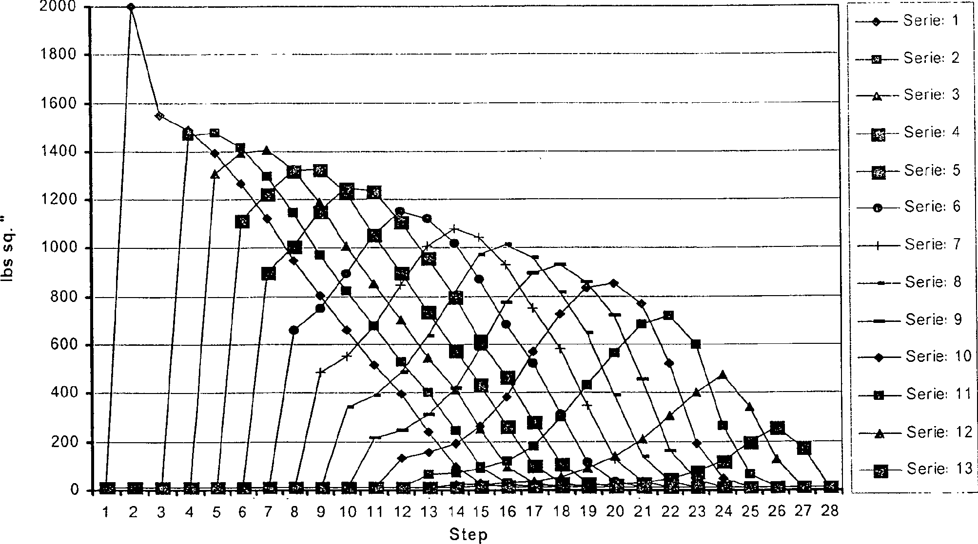
Figure 00400002
Graphical representation 3b Stator pressure profile
Figure 00400002

Graphische Darstellung 4 Verhältnis von Länge zum Bereich i. Vgl. zur Länge einer retortenförmigen Kammer

Figure 00410001
Graphical representation 4 ratio of length to area i. See the length of a retort-shaped chamber
Figure 00410001

Claims (44)

Eine Maschine, einschließlich einer Verbrennungskonstruktion (116) bestehend aus einem Rotor (210, 1910, 2112) und einem Stator (310, 1912, 2114), in der eine Verbrennungskammer (316) im Stator (310, 1912, 2114) definiert ist, und eine Flüssigkeitsaufnahmekammer (234) im Rotor (210, 1910, 2112) definiert ist, wobei aus der Verbrennungskammer (316) Verbrennungsgas in die Aufnahmekammer (234) expandieren kann, wodurch Bewegungsenergie vom Verbrennungsgas auf den Rotor (210, 1910, 2112) übertragen wird, wobei der Rotor (210, 1910, 2112) eine Vielzahl von Ausdehnungskammern (232) schrittweise ansteigenden Volumens hat, in die das Gas expandieren kann, und der Stator (310, 1912, 2114) eine Vielzahl von Statorausdehnungskammern (332) schrittweise ansteigenden Volumens hat, in die das Gas aus den Kammern (234, 232) des Rotors (210, 1910, 2112) expandieren kann.A machine, including a combustion construction ( 116 ) consisting of a rotor ( 210 . 1910 . 2112 ) and a stator ( 310 . 1912 . 2114 ), in which a combustion chamber ( 316 ) in the stator ( 310 . 1912 . 2114 ), and a fluid receiving chamber ( 234 ) in the rotor ( 210 . 1910 . 2112 ), wherein from the combustion chamber ( 316 ) Combustion gas into the receiving chamber ( 234 ), whereby kinetic energy from the combustion gas to the rotor ( 210 . 1910 . 2112 ), wherein the rotor ( 210 . 1910 . 2112 ) a plurality of expansion chambers ( 232 ) has gradually increasing volume into which the gas can expand, and the stator ( 310 . 1912 . 2114 ) a plurality of stator expansion chambers ( 332 ) has gradually increasing volume into which the gas from the chambers ( 234 . 232 ) of the rotor ( 210 . 1910 . 2112 ) can expand. Eine Maschine gemäß Anspruch 1, in der die Aufnahmekammer (234) ein Volumen hat, das größer als das mehrerer der Rotorausdehnungskammern (232) ist.A machine according to claim 1, in which the receiving chamber ( 234 ) has a volume larger than that of a plurality of the rotor expansion chambers ( 232 ). Eine Maschine gemäß Anspruch 1 oder Anspruch 2, bei der der Rotor (210, 1910, 2112) eine Transferkammer (230) hat, durch die Verbrennungsgas während eines Teils der Drehung des Rotors (210, 1910, 21 12) in die Verbrennungskammer (316) strömen kann.A machine according to claim 1 or claim 2, wherein the rotor ( 210 . 1910 . 2112 ) a transfer chamber ( 230 ) by the combustion gas during part of the rotation of the rotor ( 210 . 1910 . 21 12) into the combustion chamber ( 316 ) can flow. Eine Maschine gemäß jedem der vorherigen Ansprüche, in der ein Funkenzündgerät zusammen mit der Verbrennungskammer (316) vorhanden ist, um eine Ladung verbrennbarer Flüssigkeit zu entzünden, die in die Kammer (316) geströmt ist.A machine according to any one of the preceding claims, in which a spark ignitor together with the combustion chamber ( 316 ) to ignite a charge of combustible liquid entering the chamber ( 316 ) has flowed. Eine Maschine gemäß Anspruch 4, bei der das Zündgerät eine Zündkerze hat.A machine according to claim 4, where the ignitor is a spark plug Has. Eine Maschine gemäß jedem der vorherigen Ansprüche, bei der der Rotor (210, 1910, 2112) oder der Stator (310, 1912, 2114) oder. beide aus einem Material gefertigt ist, das selbstschmierende Eigenschaften hat.A machine according to any one of the preceding claims, wherein the rotor ( 210 . 1910 . 2112 ) or the stator ( 310 . 1912 . 2114 ) or. both made of a material that has self-lubricating properties. Eine Maschine gemäß Anspruch 6, bei der entweder der Rotor (210, 1910, 2112) oder der Stator (310, 1912, 2114) aus rundlichem Graphiteisen besteht.A machine according to claim 6, wherein either the rotor ( 210 . 1910 . 2112 ) or the stator ( 310 . 1912 . 2114 ) consists of roundish graphite iron. Eine Maschine gemäß jedem der vorherigen Ansprüche, die einen Ölnebelinjektor hat, der in einen Raum zwischen dem Rotor (210, 1910, 2112) und dem Stator (310, 1912, 2114) einen Ölnebel injiziert.A machine according to any one of the preceding claims, having an oil mist injector placed in a space between the rotor (10). 210 . 1910 . 2112 ) and the stator ( 310 . 1912 . 2114 ) injected an oil mist. Eine Maschine gemäß Anspruch 8, bei der der Ölnebel in einer Position im Vorlauf der Verbrennungskammer injiziert wird.A machine according to claim 8, where the oil mist is injected in a position in the forerun of the combustion chamber. Eine Maschine gemäß jedem der vorhergen Ansprüche, die eine Schmierbürste (1610) besitzt, die zwischen dem Stator (310, 1912, 2114) und dem Rotor (210, 1910, 2112) Schmiermittel hinzafügt.A machine according to any one of the preceding claims, comprising a lubricating brush ( 1610 ) between the stator ( 310 . 1912 . 2114 ) and the rotor ( 210 . 1910 . 2112 ) Adds lubricant. Eine Maschine gemäß Anspruch 10; Bei der das Schmiermittel Graphit ist.A machine according to claim 10; At the Lubricant is graphite. Eine Maschine gemäß jedem der vorherigen Ansprüche, bei der der Rotor (210, 1910, 2112) eine Scheibe ist und Kammern hat (234, 232), die sich zur Peripherie der Scheibe öffnen.A machine according to any one of the preceding claims, wherein the rotor ( 210 . 1910 . 2112 ) is a disk and has chambers ( 234 . 232 ), which open to the periphery of the disc. Eine Maschine gemäß jedem der vorherigen Ansprüche, bei der der Rotor (210, 1910, 2112) aus einer Rotoreinheit (210, 1910, 2112) besteht, zu der auch ein Rotorgussstück (220) gehört.A machine according to any one of the preceding claims, wherein the rotor ( 210 . 1910 . 2112 ) from a rotor unit ( 210 . 1910 . 2112 ), to which a rotor casting ( 220 ) belongs. Eine Maschine wie in Anspruch 12, bei der das Rotorgussstück (220) wie eine Scheibe geformt ist und periphere Öffnungen zu dahinter liegenden Hohlräumen besitzt.A machine as in claim 12, wherein the rotor casting ( 220 ) is shaped like a disc and has peripheral openings to underlying cavities. Eine Maschine wie in Anspruch 14, bei der die Rotoreinheit (210, 1910, 2112) außerdem Endplatten (222) besitzt, die am Rotorgussstück (220) gesichert sind, um diese Öffnungen axial zu schließen.A machine as in claim 14, wherein the rotor unit ( 210 . 1910 . 2112 ) also end plates ( 222 ), which on Rotorgussstück ( 220 ) are secured to close these openings axially. Eine Maschine gemäß jedem Anspruch nach 13 bis 15 einschließlich mehrerer Rotorgussstücke (220), die zwischen Endplatten montiert sind, um eine Verbrennungseinheit größerer Verbrennungskapazität zu bilden.A machine according to any one of claims 13 to 15, including a plurality of rotor castings ( 220 ) mounted between end plates to form a combustion unit of larger combustion capacity. Eine Maschine gemäß Anspruch 16, bei der ein Abstandsstück zwischen nebeneinander liegenden Gussstücken (220) angebracht ist, um zur Wärmeableitung von der Verbrennungseinheit beizutragen, insbesondere von den Rotorgussstücken (220).A machine according to claim 16, wherein a spacer between adjacent castings ( 220 ) to contribute to heat dissipation from the combustion unit, in particular from the rotor castings ( 220 ). Eine Maschine gemäß Anspruch 17, bei der das Abstandsstück einen Durchlaß hat, der auf die Leitung der Kühlungsflüssigkeit der Rotorgussstücke (220) ausgerichtet ist.A machine according to claim 17, wherein the spacer has a passage which is directed to the duct of the cooling liquid of the rotor castings ( 220 ) is aligned. Eine Maschine gemäß jedem der vorherigen Ansprüche, bei der der Stator (310, 1912, 2114) aus einer Statoreinheit (310, 1912, 2114) besteht, die ein Statorgussstück (320) hat.A machine according to any one of the preceding claims, wherein the stator ( 310 . 1912 . 2114 ) from a stator unit ( 310 . 1912 . 2114 ), which is a Statorgussstück ( 320 ) Has. Eine Maschine gemäß Anspruch 19, bei der das Statorgussstück (320) eine Form hat, die teilweise die Rotoreinheit (210, 1910, 2112) umgibt, die Öffnungen in dahinter liegende Hohlräume hat.A machine according to claim 19, wherein the stator casting ( 320 ) has a shape that partially covers the rotor unit ( 210 . 1910 . 2112 ), which has openings in cavities behind it. Eine Maschine gemäß Anspruch 20, bei der die Statoreinheit (310, 1912, 2114) zusätzlich Endplatten (322) umfaßt, die am Gussstück des Stators (320) gesichert sind und diese Öffnungen axial schließen.A machine according to claim 20, wherein the stator unit ( 310 . 1912 . 2114 ) additional end plates ( 322 ) formed on the casting of the stator ( 320 ) are secured and close these openings axially. Eine Maschine gemäß Anspruch 21, bei der mehrere Statorgussstücke (320) zusammen Endplatten (322) montiert sein können, um eine Verbrennungskammer größerer Kapazität zu bieten.A machine according to claim 21, wherein a plurality of stator castings ( 320 ) together end plates ( 322 ) to provide a larger capacity combustion chamber. Eine Maschine gemäß Anspruch 22, bei der ein Abstandsstück zwischen nebeneinander liegenden Statorgussstücken (320) angebracht ist, um zur Wärmeableitung von der Verbrennungseinheit beizutragen, insbesondere von den Statorgussstücken (320).A machine according to claim 22, wherein a spacer between adjacent stator castings ( 320 ) to contribute to heat dissipation from the combustion unit, in particular from the Statorgussstücken ( 320 ). Eine Maschine gemäß Anspruch 23, bei der das Abstandsstück Löcher hat, um die Verbrennungskammern der verschiedenen Statorgussstücke (320) in axialer Richtung zu verbinden.A machine according to claim 23, wherein the spacer has holes to communicate the combustion chambers of the various stator castings ( 320 ) in the axial direction. Eine Maschine gemäß jedem der vorherigen Ansprüche mit einem Abstandsreglersystem zur Steuerung der Trennung des Rotors (210, 1910, 2112) vom Stator (310, 1912, 2114) während des Betriebs der Maschine.A machine according to any one of the preceding claims, including a distance control system for controlling the separation of the rotor ( 210 . 1910 . 2112 ) from the stator ( 310 . 1912 . 2114 ) during operation of the machine. Eine Maschine gemäß Anspruch 25, bei der das Abstandsreglersystem den Stator (310, 1912, 2114) radial vom Rotor (210, 1910, 2112) bewegt.A machine according to claim 25, wherein the distance control system drives the stator ( 310 . 1912 . 2114 ) radially from the rotor ( 210 . 1910 . 2112 ) emotional. Eine Maschine gemäß jedem der Ansprüche 1 bis 11, bei der der Rotor (210, 1910, 2112) als Stumpf geformt ist, der Kammern hat, die sich zu Stumpfperipherie öffnen.A machine according to any one of claims 1 to 11, wherein the rotor ( 210 . 1910 . 2112 ) is shaped as a stump, which has chambers that open to stump periphery. Eine Maschine gemäß Anspruch 27, bei der der Stator (310, 1912, 2114) den Rotor (210, 1910, 2112) teilweise umgibt.A machine according to claim 27, wherein the stator ( 310 . 1912 . 2114 ) the rotor ( 210 . 1910 . 2112 ) partially surrounds. Eine Maschine gemäß Anspruch 27 oder 28 mit einem Abstandsreglersystem. zur Steuerung der Trennung von Rotor (210, 1910, 2112) und Stator (310, 1912, 2114) während des Betriebs der Maschine.A machine according to claim 27 or 28, including a distance control system. for controlling the separation of rotor ( 210 . 1910 . 2112 ) and stator ( 310 . 1912 . 2114 ) during operation of the machine. Eine Maschine gemäß Anspruch 29, bei der das Abstandsreglersystem den Stator (310, 1912, 2114) axial vom Rotor (210, 1910, 2112) bewegt.A machine according to claim 29, wherein the distance control system drives the stator ( 310 . 1912 . 2114 ) axially from the rotor ( 210 . 1910 . 2112 ) emotional. Eine Maschine gemäß jedem der Ansprüche 25, 26, 29 oder 30, bei der das Abstandsreglersystem einen kontaktlosen Sensor (S) besitzt.A machine according to any one of claims 25, 26, 29 or 30, in which the distance control system is a contactless Sensor (S) has. Eine Maschine gemäß Anspruch 31, bei der der Sensor (S) durch Kapazitätserfassung, induktives Erfassen oder eine Kombination von kapazitiver und induktiver Erfassung funktioniert.A machine according to claim 31, wherein the Sensor (S) through capacity detection, Inductive detection or a combination of capacitive and inductive Capture works. Eine Maschine gemäß jedem der Ansprüche 1 bis 11, bei der der Rotor (210, 1910, 2112) und der Stator (310, 1912, 2114) beide wie eine Scheibe geformt sind und die Verbrennungskammer (316) zwischen den flachen Flächen des Rotors (210, 1910, 2112) und des Stators (310, 1912, 2114) definiert ist.A machine according to any one of claims 1 to 11, wherein the rotor ( 210 . 1910 . 2112 ) and the stator ( 310 . 1912 . 2114 ) are both shaped like a disk and the combustion chamber ( 316 ) between the flat surfaces of the rotor ( 210 . 1910 . 2112 ) and the stator ( 310 . 1912 . 2114 ) is defined. Eine Maschine gemäß jedem der vorherigen Ansprüche, die zusätzlich einen Kompressor (110) besitzt, um Verbrennungsluft an die Verbrennungseinheit (316) zu liefern.A machine according to any one of the preceding claims, additionally comprising a compressor ( 110 ) to supply combustion air to the combustion unit ( 316 ) to deliver. Eine Maschine gemäß Anspruch 34, bei der der Kompressor (110) vom Rotor (210, 1910, 2112) angetrieben wird.A machine according to claim 34, wherein the compressor ( 110 ) from the rotor ( 210 . 1910 . 2112 ) is driven. Eine Maschine gemäß Anspruch 35, bei der der Kompressor (110) und der Rotor (210, 1910, 2112) auf einer gemeinsamen Welle (122) oder miteirander verbundenen koaxialen Wellen sitzen.A machine according to claim 35, wherein the compressor ( 110 ) and the rotor ( 210 . 1910 . 2112 ) on a common wave ( 122 ) or with coaxial shafts connected to each other. Eine Maschine gemäß jedem der Ansprüche 34 bis 36, bei der in einer Konfiguration mit einer Zündung der Kompressor (110) Verbrennungsluft mit einem Druck von 4 bis 7 bar liefert, und in einer Kompressionszündungskonfiguration der Kompressor (110) Verbrennungsluft mit einem Druck von 9 bis 15 bar liefert.A machine according to any one of claims 34 to 36, wherein in a configuration with one ignition the compressor ( 110 ) Provides combustion air at a pressure of 4 to 7 bar, and in a compression ignition configuration, the compressor ( 110 ) Delivers combustion air at a pressure of 9 to 15 bar. Eine Maschine gemäß jedem der Ansprüche 34 bis 37, bei der ein Zwischenkühler (112) zwischen dem Kompressor (110) und der Verbrennungseinheit (116) angebracht ist, um der Verbrennungsluft Wärme zu entziehen.A machine according to any one of claims 34 to 37, wherein an intercooler ( 112 ) between the compressor ( 110 ) and the combustion unit ( 116 ) is mounted to extract heat from the combustion air. Eine Maschine gemäß Anspruch 33, bei der in einer Zündungskonfiguration der Kompressor (110) Verbrennungsluft mit einem Druck von 6 bis 12 bar liefert und in einer Kompressionszündungskonfiguration der Kompressor (110) Verbrennungsluft mit einem Druck von 20 bis 30 bar liefert.A machine according to claim 33, wherein in an ignition configuration the compressor ( 110 ) Supplies combustion air at a pressure of 6 to 12 bar and in a compression ignition configuration the compressor ( 110 ) Provides combustion air at a pressure of 20 to 30 bar. Eine Maschine gemäß jedem der vorhergehenden Ansprüche, bei der in einen Verbrennungsluftstrom außerhalb der Verbrennungseinheit (116) Brennstoff injiziert wird.A machine according to any one of the preceding claims, wherein in a combustion air stream outside the combustion unit ( 116 ) Fuel is injected. Eine Maschine gemäß jedem der vorhergehenden Ansprüche, bei der Brennstoff in eine Kammer innerhalb der Verbrennungseinheit (116) injiziert wird.A machine according to any one of the preceding claims, wherein fuel is introduced into a chamber within the combustion unit ( 116 ) is injected. Eine Maschine gemäß jedem der vorhergehenden Ansprüche, bei der Wasser zusammen mit Luft und Brennstoff in die Verbrennungskammer (316) eingeführt wird.A machine according to any one of the preceding claims, wherein water, together with air and fuel, enters the combustion chamber ( 316 ) is introduced. Eine Maschine gemäß Anspruch 42, bei der während der Verbrennung das Wasser verdampft und in die Aufnahmekammer (234) expandiert und zumindest einen Teil seiner Bewegungsenergie auf den Rotor (210, 1910, 2112) überträgt.A machine according to claim 42, wherein during the combustion the water evaporates and enters the receiving chamber ( 234 ) expands and at least part of its kinetic energy on the rotor ( 210 . 1910 . 2112 ) transmits. Eine Maschine gemäß jedem der vorhergehenden Ansprüche, bei der der Stator (310, 1912, 2114) und/oder der Rotor (210, 1910, 2112) ein Gussstück zwischen Endplatten einschließt.A machine according to any one of the preceding claims, wherein the stator ( 310 . 1912 . 2114 ) and / or the rotor ( 210 . 1910 . 2112 ) includes a casting between end plates.
DE69910607T 1998-11-21 1999-11-19 ROTATION internal combustion engine Expired - Lifetime DE69910607T2 (en)

Applications Claiming Priority (3)

Application Number Priority Date Filing Date Title
GBGB9825504.5A GB9825504D0 (en) 1998-11-21 1998-11-21 An engine
GB9825504 1998-11-21
PCT/GB1999/003844 WO2000031394A2 (en) 1998-11-21 1999-11-19 An engine

Publications (2)

Publication Number Publication Date
DE69910607D1 DE69910607D1 (en) 2003-09-25
DE69910607T2 true DE69910607T2 (en) 2004-07-01

Family

ID=10842807

Family Applications (1)

Application Number Title Priority Date Filing Date
DE69910607T Expired - Lifetime DE69910607T2 (en) 1998-11-21 1999-11-19 ROTATION internal combustion engine

Country Status (9)

Country Link
US (1) US6584759B1 (en)
EP (1) EP1131548B1 (en)
JP (1) JP4478824B2 (en)
AT (1) ATE247770T1 (en)
AU (1) AU1281700A (en)
CA (1) CA2350918C (en)
DE (1) DE69910607T2 (en)
GB (1) GB9825504D0 (en)
WO (1) WO2000031394A2 (en)

Families Citing this family (13)

* Cited by examiner, † Cited by third party
Publication number Priority date Publication date Assignee Title
GB0218849D0 (en) * 2002-08-14 2002-09-25 Rolls Royce Plc Lubrication system for gas turbine engine
US7695275B2 (en) * 2004-06-02 2010-04-13 Fuel Management, Inc. Air:fluid distribution system and method
FR2871850B1 (en) * 2004-06-18 2006-08-04 Claude Louis Adam OIL REVOLUTION MOTOR: ENGINE COOLING; HELIOGYRES: ADDITIVES
US7370836B2 (en) * 2005-08-09 2008-05-13 Greene Leonard M Missile defense system and methods for evading heat seeking missiles
US7533530B2 (en) * 2007-01-19 2009-05-19 Courtright Geoffrey B Engine for the efficient production of an energized fluid
DE102008019182A1 (en) * 2008-04-17 2009-10-22 Voith Patent Gmbh Electromechanical actuator for actuating valves
US8156919B2 (en) * 2008-12-23 2012-04-17 Darrow David S Rotary vane engines with movable rotors, and engine systems comprising same
EP2428642A1 (en) * 2010-09-08 2012-03-14 Siemens Aktiengesellschaft Rotor for a steam turbine with circumferential recesses inclined in respect to the rotor main axis
FR2971297A1 (en) * 2010-11-08 2012-08-10 Claude Louis Adam Continuous or discontinuous mixed rotary positive ignition engine for e.g. vehicle, has solenoid valves assuring sealing of intake valve, and photoelectric cells for controlling switches, where lamp placed on cells emits light beams
US8328591B2 (en) * 2010-12-15 2012-12-11 General Electric Company System, method, and article of manufacture for cooling and filtering engine intake air
US10519858B2 (en) * 2016-07-22 2019-12-31 Brent Wei-Teh LEE Engine, rotary device, power generator, power generation system, and methods of making and using the same
CN108104977A (en) * 2017-10-09 2018-06-01 李钢坤 A kind of vortex-spraying type is without stroke rotary engine
US10976052B2 (en) * 2017-10-25 2021-04-13 General Electric Company Volute trapped vortex combustor assembly

Family Cites Families (12)

* Cited by examiner, † Cited by third party
Publication number Priority date Publication date Assignee Title
US1546049A (en) * 1925-07-14 Reentrant turbine
FR9155E (en) * 1907-04-16 1908-09-07 Armand Le Compagnon Air and oil turbine
FR376792A (en) 1907-04-16 1907-08-20 Armand Le Compagnon Air and oil turbine
US1076733A (en) * 1912-02-23 1913-10-28 Universal Turbine Company Turbine.
US1582174A (en) * 1924-07-21 1926-04-27 John L Smith Turbine
FR801662A (en) * 1935-12-19 1936-08-12 Tangential action combustion or explosion turbine
FR977740A (en) * 1942-10-28 1951-04-04 Explosive gas turbo-engine compressor unit
US2444213A (en) * 1944-10-17 1948-06-29 Harvey B Weeks Rotary turbine
FR1192930A (en) * 1957-04-15 1959-10-29 Improved explosion turbine
US3397864A (en) * 1967-02-27 1968-08-20 Verner E. Sprouse Multi-stage rotary engine
DE1601582A1 (en) * 1967-05-23 1970-01-29 Walter Konath Turbo roller block motor
US5966927A (en) * 1997-03-31 1999-10-19 Wilson; Michael A. Efficiency enhanced turbine engine

Also Published As

Publication number Publication date
EP1131548A2 (en) 2001-09-12
WO2000031394A3 (en) 2001-03-01
ATE247770T1 (en) 2003-09-15
AU1281700A (en) 2000-06-13
JP2002530586A (en) 2002-09-17
DE69910607D1 (en) 2003-09-25
JP4478824B2 (en) 2010-06-09
EP1131548B1 (en) 2003-08-20
WO2000031394A2 (en) 2000-06-02
GB9825504D0 (en) 1999-01-13
CA2350918A1 (en) 2000-06-02
US6584759B1 (en) 2003-07-01
CA2350918C (en) 2008-01-22

Similar Documents

Publication Publication Date Title
DE69910607T2 (en) ROTATION internal combustion engine
DE3412283C2 (en) Turbo compound engine
DE2916423A1 (en) COMBUSTION MACHINE
DE2352336A1 (en) ELECTRIC GENERATOR, IN PARTICULAR FOR COMBUSTION MACHINERY
DE1061132B (en) Turbocharger for multi-cylinder internal combustion engines
EP0328602B1 (en) Device for introducing fuel into the combustion chamber of an internal combustion engine
EP2846019A1 (en) Method for operating a combustion engine and combustion engine for executing the method
EP0046872B1 (en) Combustion piston engine with exhaust gas turbocharger
DE3318136A1 (en) CHARGING DEVICE FOR CHARGING COMBUSTION ENGINES
DE102011109966A1 (en) Rotary piston engine, in particular with ignition chamber rotating rotary piston
DE3145835A1 (en) Method for the operation of the exhaust gas turbocharger of a piston internal combustion engine and piston internal combustion engine
EP1645719A1 (en) Engine and method for power generation
EP0240467B1 (en) Rotating-reciprocating machine
EP0278117B1 (en) Piston internal-combustion engine with an increased volumetric efficiency due to fresh gas resonant oscillations
DE3234051C2 (en) Displacement machine or machine
DE2250589A1 (en) ROTARY PISTON MACHINE
DE102006014425A1 (en) Fuel rotary piston engine e.g. petrol engine, for e.g. driving motor vehicle, has operating area partitioning controllable separating pushers into operating chambers from stator, where chambers reduce and increase piston`s rotation movement
DE102010018654B4 (en) Cyclic heat engine
DE102015116063A1 (en) Internal combustion engine
DE3804411A1 (en) Centre axis rotary engine of the rotating piston type
EP2650510B1 (en) Thermal engine for free piston compressor
DE3424310C2 (en) Device for generating mechanical energy in a turbine-like internal combustion engine
DE202006018098U1 (en) Energy conversion system
AT410965B (en) COMPOSITE MOTOR
DE2739129C2 (en) Free piston gas turbine plant

Legal Events

Date Code Title Description
8327 Change in the person/name/address of the patent owner

Owner name: HEAP, ROLAND GRANT, PAWLETT, SOMERSET, GB

8328 Change in the person/name/address of the agent

Representative=s name: BOEHMERT & BOEHMERT, 28209 BREMEN

8364 No opposition during term of opposition