DE69733532T2 - FILM OF HYBRID POLYMER - Google Patents
FILM OF HYBRID POLYMER Download PDFInfo
- Publication number
- DE69733532T2 DE69733532T2 DE69733532T DE69733532T DE69733532T2 DE 69733532 T2 DE69733532 T2 DE 69733532T2 DE 69733532 T DE69733532 T DE 69733532T DE 69733532 T DE69733532 T DE 69733532T DE 69733532 T2 DE69733532 T2 DE 69733532T2
- Authority
- DE
- Germany
- Prior art keywords
- film
- polymer film
- acrylate
- radiation
- plasma
- Prior art date
- Legal status (The legal status is an assumption and is not a legal conclusion. Google has not performed a legal analysis and makes no representation as to the accuracy of the status listed.)
- Expired - Lifetime
Links
Classifications
-
- B—PERFORMING OPERATIONS; TRANSPORTING
- B05—SPRAYING OR ATOMISING IN GENERAL; APPLYING FLUENT MATERIALS TO SURFACES, IN GENERAL
- B05D—PROCESSES FOR APPLYING FLUENT MATERIALS TO SURFACES, IN GENERAL
- B05D1/00—Processes for applying liquids or other fluent materials
- B05D1/60—Deposition of organic layers from vapour phase
-
- B—PERFORMING OPERATIONS; TRANSPORTING
- B32—LAYERED PRODUCTS
- B32B—LAYERED PRODUCTS, i.e. PRODUCTS BUILT-UP OF STRATA OF FLAT OR NON-FLAT, e.g. CELLULAR OR HONEYCOMB, FORM
- B32B27/00—Layered products comprising a layer of synthetic resin
-
- C—CHEMISTRY; METALLURGY
- C23—COATING METALLIC MATERIAL; COATING MATERIAL WITH METALLIC MATERIAL; CHEMICAL SURFACE TREATMENT; DIFFUSION TREATMENT OF METALLIC MATERIAL; COATING BY VACUUM EVAPORATION, BY SPUTTERING, BY ION IMPLANTATION OR BY CHEMICAL VAPOUR DEPOSITION, IN GENERAL; INHIBITING CORROSION OF METALLIC MATERIAL OR INCRUSTATION IN GENERAL
- C23C—COATING METALLIC MATERIAL; COATING MATERIAL WITH METALLIC MATERIAL; SURFACE TREATMENT OF METALLIC MATERIAL BY DIFFUSION INTO THE SURFACE, BY CHEMICAL CONVERSION OR SUBSTITUTION; COATING BY VACUUM EVAPORATION, BY SPUTTERING, BY ION IMPLANTATION OR BY CHEMICAL VAPOUR DEPOSITION, IN GENERAL
- C23C14/00—Coating by vacuum evaporation, by sputtering or by ion implantation of the coating forming material
- C23C14/06—Coating by vacuum evaporation, by sputtering or by ion implantation of the coating forming material characterised by the coating material
- C23C14/14—Metallic material, boron or silicon
- C23C14/20—Metallic material, boron or silicon on organic substrates
-
- H—ELECTRICITY
- H01—ELECTRIC ELEMENTS
- H01G—CAPACITORS; CAPACITORS, RECTIFIERS, DETECTORS, SWITCHING DEVICES OR LIGHT-SENSITIVE DEVICES, OF THE ELECTROLYTIC TYPE
- H01G4/00—Fixed capacitors; Processes of their manufacture
- H01G4/002—Details
- H01G4/018—Dielectrics
- H01G4/20—Dielectrics using combinations of dielectrics from more than one of groups H01G4/02 - H01G4/06
-
- B—PERFORMING OPERATIONS; TRANSPORTING
- B05—SPRAYING OR ATOMISING IN GENERAL; APPLYING FLUENT MATERIALS TO SURFACES, IN GENERAL
- B05D—PROCESSES FOR APPLYING FLUENT MATERIALS TO SURFACES, IN GENERAL
- B05D3/00—Pretreatment of surfaces to which liquids or other fluent materials are to be applied; After-treatment of applied coatings, e.g. intermediate treating of an applied coating preparatory to subsequent applications of liquids or other fluent materials
- B05D3/14—Pretreatment of surfaces to which liquids or other fluent materials are to be applied; After-treatment of applied coatings, e.g. intermediate treating of an applied coating preparatory to subsequent applications of liquids or other fluent materials by electrical means
- B05D3/141—Plasma treatment
- B05D3/142—Pretreatment
- B05D3/144—Pretreatment of polymeric substrates
-
- B—PERFORMING OPERATIONS; TRANSPORTING
- B05—SPRAYING OR ATOMISING IN GENERAL; APPLYING FLUENT MATERIALS TO SURFACES, IN GENERAL
- B05D—PROCESSES FOR APPLYING FLUENT MATERIALS TO SURFACES, IN GENERAL
- B05D3/00—Pretreatment of surfaces to which liquids or other fluent materials are to be applied; After-treatment of applied coatings, e.g. intermediate treating of an applied coating preparatory to subsequent applications of liquids or other fluent materials
- B05D3/14—Pretreatment of surfaces to which liquids or other fluent materials are to be applied; After-treatment of applied coatings, e.g. intermediate treating of an applied coating preparatory to subsequent applications of liquids or other fluent materials by electrical means
- B05D3/141—Plasma treatment
- B05D3/145—After-treatment
- B05D3/147—Curing
-
- Y—GENERAL TAGGING OF NEW TECHNOLOGICAL DEVELOPMENTS; GENERAL TAGGING OF CROSS-SECTIONAL TECHNOLOGIES SPANNING OVER SEVERAL SECTIONS OF THE IPC; TECHNICAL SUBJECTS COVERED BY FORMER USPC CROSS-REFERENCE ART COLLECTIONS [XRACs] AND DIGESTS
- Y10—TECHNICAL SUBJECTS COVERED BY FORMER USPC
- Y10T—TECHNICAL SUBJECTS COVERED BY FORMER US CLASSIFICATION
- Y10T428/00—Stock material or miscellaneous articles
- Y10T428/12—All metal or with adjacent metals
- Y10T428/12493—Composite; i.e., plural, adjacent, spatially distinct metal components [e.g., layers, joint, etc.]
- Y10T428/12535—Composite; i.e., plural, adjacent, spatially distinct metal components [e.g., layers, joint, etc.] with additional, spatially distinct nonmetal component
- Y10T428/12556—Organic component
- Y10T428/12569—Synthetic resin
-
- Y—GENERAL TAGGING OF NEW TECHNOLOGICAL DEVELOPMENTS; GENERAL TAGGING OF CROSS-SECTIONAL TECHNOLOGIES SPANNING OVER SEVERAL SECTIONS OF THE IPC; TECHNICAL SUBJECTS COVERED BY FORMER USPC CROSS-REFERENCE ART COLLECTIONS [XRACs] AND DIGESTS
- Y10—TECHNICAL SUBJECTS COVERED BY FORMER USPC
- Y10T—TECHNICAL SUBJECTS COVERED BY FORMER US CLASSIFICATION
- Y10T428/00—Stock material or miscellaneous articles
- Y10T428/12—All metal or with adjacent metals
- Y10T428/12493—Composite; i.e., plural, adjacent, spatially distinct metal components [e.g., layers, joint, etc.]
- Y10T428/12535—Composite; i.e., plural, adjacent, spatially distinct metal components [e.g., layers, joint, etc.] with additional, spatially distinct nonmetal component
- Y10T428/12576—Boride, carbide or nitride component
-
- Y—GENERAL TAGGING OF NEW TECHNOLOGICAL DEVELOPMENTS; GENERAL TAGGING OF CROSS-SECTIONAL TECHNOLOGIES SPANNING OVER SEVERAL SECTIONS OF THE IPC; TECHNICAL SUBJECTS COVERED BY FORMER USPC CROSS-REFERENCE ART COLLECTIONS [XRACs] AND DIGESTS
- Y10—TECHNICAL SUBJECTS COVERED BY FORMER USPC
- Y10T—TECHNICAL SUBJECTS COVERED BY FORMER US CLASSIFICATION
- Y10T428/00—Stock material or miscellaneous articles
- Y10T428/14—Layer or component removable to expose adhesive
- Y10T428/1462—Polymer derived from material having at least one acrylic or alkacrylic group or the nitrile or amide derivative thereof [e.g., acrylamide, acrylate ester, etc.]
-
- Y—GENERAL TAGGING OF NEW TECHNOLOGICAL DEVELOPMENTS; GENERAL TAGGING OF CROSS-SECTIONAL TECHNOLOGIES SPANNING OVER SEVERAL SECTIONS OF THE IPC; TECHNICAL SUBJECTS COVERED BY FORMER USPC CROSS-REFERENCE ART COLLECTIONS [XRACs] AND DIGESTS
- Y10—TECHNICAL SUBJECTS COVERED BY FORMER USPC
- Y10T—TECHNICAL SUBJECTS COVERED BY FORMER US CLASSIFICATION
- Y10T428/00—Stock material or miscellaneous articles
- Y10T428/31504—Composite [nonstructural laminate]
- Y10T428/31511—Of epoxy ether
- Y10T428/31515—As intermediate layer
-
- Y—GENERAL TAGGING OF NEW TECHNOLOGICAL DEVELOPMENTS; GENERAL TAGGING OF CROSS-SECTIONAL TECHNOLOGIES SPANNING OVER SEVERAL SECTIONS OF THE IPC; TECHNICAL SUBJECTS COVERED BY FORMER USPC CROSS-REFERENCE ART COLLECTIONS [XRACs] AND DIGESTS
- Y10—TECHNICAL SUBJECTS COVERED BY FORMER USPC
- Y10T—TECHNICAL SUBJECTS COVERED BY FORMER US CLASSIFICATION
- Y10T428/00—Stock material or miscellaneous articles
- Y10T428/31504—Composite [nonstructural laminate]
- Y10T428/31533—Of polythioether
-
- Y—GENERAL TAGGING OF NEW TECHNOLOGICAL DEVELOPMENTS; GENERAL TAGGING OF CROSS-SECTIONAL TECHNOLOGIES SPANNING OVER SEVERAL SECTIONS OF THE IPC; TECHNICAL SUBJECTS COVERED BY FORMER USPC CROSS-REFERENCE ART COLLECTIONS [XRACs] AND DIGESTS
- Y10—TECHNICAL SUBJECTS COVERED BY FORMER USPC
- Y10T—TECHNICAL SUBJECTS COVERED BY FORMER US CLASSIFICATION
- Y10T428/00—Stock material or miscellaneous articles
- Y10T428/31504—Composite [nonstructural laminate]
- Y10T428/3154—Of fluorinated addition polymer from unsaturated monomers
-
- Y—GENERAL TAGGING OF NEW TECHNOLOGICAL DEVELOPMENTS; GENERAL TAGGING OF CROSS-SECTIONAL TECHNOLOGIES SPANNING OVER SEVERAL SECTIONS OF THE IPC; TECHNICAL SUBJECTS COVERED BY FORMER USPC CROSS-REFERENCE ART COLLECTIONS [XRACs] AND DIGESTS
- Y10—TECHNICAL SUBJECTS COVERED BY FORMER USPC
- Y10T—TECHNICAL SUBJECTS COVERED BY FORMER US CLASSIFICATION
- Y10T428/00—Stock material or miscellaneous articles
- Y10T428/31504—Composite [nonstructural laminate]
- Y10T428/31678—Of metal
- Y10T428/31681—Next to polyester, polyamide or polyimide [e.g., alkyd, glue, or nylon, etc.]
-
- Y—GENERAL TAGGING OF NEW TECHNOLOGICAL DEVELOPMENTS; GENERAL TAGGING OF CROSS-SECTIONAL TECHNOLOGIES SPANNING OVER SEVERAL SECTIONS OF THE IPC; TECHNICAL SUBJECTS COVERED BY FORMER USPC CROSS-REFERENCE ART COLLECTIONS [XRACs] AND DIGESTS
- Y10—TECHNICAL SUBJECTS COVERED BY FORMER USPC
- Y10T—TECHNICAL SUBJECTS COVERED BY FORMER US CLASSIFICATION
- Y10T428/00—Stock material or miscellaneous articles
- Y10T428/31504—Composite [nonstructural laminate]
- Y10T428/31678—Of metal
- Y10T428/31692—Next to addition polymer from unsaturated monomers
- Y10T428/31699—Ester, halide or nitrile of addition polymer
-
- Y—GENERAL TAGGING OF NEW TECHNOLOGICAL DEVELOPMENTS; GENERAL TAGGING OF CROSS-SECTIONAL TECHNOLOGIES SPANNING OVER SEVERAL SECTIONS OF THE IPC; TECHNICAL SUBJECTS COVERED BY FORMER USPC CROSS-REFERENCE ART COLLECTIONS [XRACs] AND DIGESTS
- Y10—TECHNICAL SUBJECTS COVERED BY FORMER USPC
- Y10T—TECHNICAL SUBJECTS COVERED BY FORMER US CLASSIFICATION
- Y10T428/00—Stock material or miscellaneous articles
- Y10T428/31504—Composite [nonstructural laminate]
- Y10T428/31855—Of addition polymer from unsaturated monomers
- Y10T428/31935—Ester, halide or nitrile of addition polymer
Description
TECHNISCHES GEBIETTECHNICAL TERRITORY
Die vorliegende Erfindung betrifft allgemein dünn metallisierte und nichtmetallisierte Polymerfilme, die weitere Beschichtungen und Oberflächenfunktionalisierung umfassen, die anwendungsspezifische Eigenschaften, wie verbesserte Thermostabilität, Abriebbeständigkeit, Feuchtigkeitssperr- und optische Eigenschaften verleihen, die diese Filme in Lebensmittelverpackungsanwendungen, Elektroanwendungen, die Filmkondensatoren und Kabel umfassen, Magnetbändern mit aufgedampftem Metall, Drucken, dekorativen Hüllen und optisch variablen Filmen für Sicherheitsanwendungen verwendbar machen.The The present invention relates generally to thin metallized and non-metallized Polymer films, the further coatings and surface functionalization which has application specific properties such as improved Thermal stability, Abrasion resistance, Moisture barrier and confer optical properties that make these films useful in food packaging applications, Electrical applications that include film capacitors and cables, magnetic tapes with evaporated metal, printing, decorative envelopes and optically variable Films for Make security applications usable.
TECHNISCHER HINTERGRUNDTECHNICAL BACKGROUND
Metallisierte und nichtmetallisierte Filme werden üblicherweise in einer Vielzahl von Elektro-, Verpackungs- und dekorativen Anwendungen verwendet. Obwohl das Anwendungsgebiet sehr breit ist, sind die gewünschten Eigenschaften der verschiedenen Filme grundlegend die gleichen. Diese gewünschten Eigenschaften umfassen mechanische Festigkeit, thermische und chemische Beständigkeit, Abriebbeständigkeit, Feuchtigkeits- und Sauerstoffsperreigenschaft und Oberflächenfunktionalität, die eine Benetzung, Adhäsion, Gleitung und dgl. unterstützt. Infolgedessen wurde eine Vielzahl von Hybridfilmen entwickelt, die einem breiten Bereich von Anwendungen dienen.metallized and non-metallized films are commonly used in a variety of ways used by electrical, packaging and decorative applications. Although the field of application is very broad, the desired Characteristics of the different films basically the same. These desired Properties include mechanical strength, thermal and chemical Resistance, Abrasion resistance, moisture and oxygen barrier property and surface functionality, the one Wetting, adhesion, gliding and the like. Supported. As a result, a variety of hybrid films have been developed serve a wide range of applications.
Allgemein verwenden hybridmetallisierte und polymerbeschichtete Filme eine Vielzahl von Produktionsverfahren. Beispielsweise werden metallisierte Polymerfilme üblicher weise korona-, flamm- oder plasmabehandelt, um die Adhäsion des Metalls an der Polymeroberfläche zu fördern (US-Patente 5 019 210 und 4 740 385); oder ionenstrahlbehandelt und anschließend elektronenstrahlbehandelt, um die Adhäsion und Einebnung des Films auf einem Substrat durch elektrostatische Kraft zu fördern (US-Patent 5 087 476). Polymerbeschichtungen, die verschiedenen Funktionen, wie Bedruckbarkeit, Adhäsionsförderung, Abriebbeständigkeit, optischen und elektrischen Eigenschaften, dienen, wurden unter Verwendung verschiedener Techniken, die Thermohärtung, reaktive Polymerisation, Plasmapolymerisation (US-Patent 5 322 737) und Strahlungshärtung unter Verwendung von Ultraviolett- und Elektronenstrahlstrahlung umfassen, produziert (US-Patente 5 374 483, 5 445 871, 4 557 980, 5 225 272, 5 068 145, 4 670 340, 4 720 421, 4 781 965, 4 812 351, 4 67 083 und 5 085 911). Bei derartigen Anwendungen wird ein monomeres Material unter Verwendung herkömmlicher Techniken der Walzenbeschichtung, des Gusses, Aufsprühens und dgl. appliziert und die Beschichtung anschließend unter Bedingungen von atmosphärischem Druck polymerisiert.Generally use hybrid metallized and polymer coated films Variety of production processes. For example, metallized Polymer films usual way corona, flame or plasma treated to promote adhesion of the metal to the polymer surface (US patents 5,019,210 and 4,740,385); or ion beam treated and then electron beam treated, around the adhesion and leveling the film on a substrate by electrostatic To promote power (U.S. Patent 5,087,476). Polymer coatings, the various Functions such as printability, adhesion promotion, abrasion resistance, optical and electrical properties, have been used various techniques, thermosetting, reactive polymerization, Plasma polymerization (U.S. Patent 5,322,737) and radiation curing under Using ultraviolet and electron beam radiation, (U.S. Patents 5,374,483, 5,445,871, 4,557,980, 5,225,272, U.S. Pat. 5 068 145, 4 670 340, 4 720 421, 4 781 965, 4 812 351, 4 67 083 and 5,085,911). In such applications, a monomeric material using conventional techniques the roll coating, casting, spraying and the like. Applied and the coating afterwards under conditions of atmospheric Pressure polymerizes.
In jüngerer Zeit wurde eine neue Technik entwickelt, die die Bildung strahlungshärtender Beschichtungen im Vakuum unter Verwendung einer Flashverdampfungstechnik ermöglicht, die zur Bildung eines aus der Dampfphase abgelagerten dünnen flüssigen Monomers führt, das durch Strahlung gehärtet werden kann (US-Patente 4 842 893, 4 954 371 und 5 032 461 und die europäische Patentanmeldung 0 339 844). Diese Technik überwindet die Beschränkungen herkömmlicher Techniken zur Applikation der flüssigen Monomere und erfordert relativ niedrige Strahlungsdosen zur Polymerisation.In younger At the time, a new technique was developed which made the radiation-curing formation process Vacuum coatings using a flash evaporation technique allows for forming a thin liquid monomer deposited from the vapor phase leads, that cured by radiation (US Pat. Nos. 4,842,893, 4,954,371 and 5,032,461 and US Pat European Patent Application 0 339 844). This technique overcomes the limitations conventional Techniques for the application of liquid Monomers and requires relatively low radiation doses for polymerization.
Es wurde ermittelt, dass die in den obigen Literaturstellen beschriebene Vakuumpolymerbeschichtungstechnik einige entscheidende Beschränkungen hinsichtlich bestimmter mechani scher, thermischer, chemischer und morphologischer Eigenschaften aufweist, die deren Verwendbarkeit bei Verpackungsfolien, Kondensatoren, Magnetbändern mit aufgedampftem Metall und optisch variablen Filmen verringern können. Die hier offenbarte Erfindung überwindet diese Probleme und erweitert die einstufige Polymer-und-Metallvakuumbeschichtungstechnik auf neue funktionale Produkte mit einem einzigartigen Satz von Eigenschaften.It was determined to be that described in the above references Vacuum polymer coating technology has some crucial limitations with regard to certain mechanical, thermal, chemical and has morphological properties that their usability in packaging films, capacitors, magnetic tapes with vapor-deposited metal and optically variable films. The invention disclosed herein overcomes these problems and extends the single-stage polymer-and-metal vacuum coating technology on new functional products with a unique set of properties.
OFFENBARUNG DER ERFINDUNGEPIPHANY THE INVENTION
Aufgabe der vorliegenden Erfindung ist die Produktion eines Hybridpolymerfilms, der hervorragende mechanische, thermische, chemische und oberflächenmorphologische Eigenschaften aufweist. In Verbindung mit einer oder mehreren Metallbeschichtungen oder einer Keramikbeschichtung kann der Hybridfilm zur Produktion verbesserter Verpackungsfolien, Filmkondensatoren, Magnetbändern mit aufgedampftem Metall und optisch variablen Filmen verwendet werden.task the present invention is the production of a hybrid polymer film, the excellent mechanical, thermal, chemical and surface morphological Features. In conjunction with one or more metal coatings or a ceramic coating, the hybrid film can be used for production improved packaging films, film capacitors, magnetic tapes with evaporated metal and optically variable films are used.
Aufgabe dieser Erfindung ist ferner die Produktion von Hybridfilmen mit gesteuerter Oberflächenmikrorauheit. Dies umfasst Filme, die eine ebenere Oberfläche als der Basisfilm oder eine Oberfläche mit gesteuerter Mikrorauheit aufweisen.task this invention is also the production of hybrid films with controlled surface micro-roughness. This includes films that have a smoother surface than the base film or a surface having controlled microroughness.
Vorzugsweise können die Hybridpolymerfilme durch ein verbessertes Verfahren zur Applikation, Polymerisation und Entladung von einer oder mehreren Schichten von unter Vakuum abgelagerten strahlungshärtenden Monomerfilmen, die zur Produktion des Hybridpolymerfilms in einem einstufigen kontinuierlichen Verfahren verwendet werden, produziert werden.Preferably can the hybrid polymer films by an improved method of application, Polymerization and discharge of one or more layers of under vacuum deposited radiation-curable monomer films, the for the production of the hybrid polymer film in a single stage continuous Procedures used to be produced.
Gemäß der vorliegenden Erfindung umfasst der Hybridpolymer film gemäß der Definition in Anspruch 1 einen ersten Polymerfilm mit einer plasmabehandelten Oberfläche und einen zweiten Polymerfilm mit einer erste und zweiten Oberfläche, wobei die erste Oberfläche des zweiten Polymerfilms sich längs der ersten plasmabehandelten Oberfläche des ersten Polymerfilms befindet, wobei ein unter Vakuum abgelagerter strahlungspolymerisierter Monomerfilm auf der plasmabehandelten Oberfläche abgelagert ist und dieser Monomerfilm eine plasmabehandelte Oberfläche aufweist.According to the present The invention encompasses the hybrid polymer film as defined in claim 1 a first polymer film having a plasma treated surface and a second polymer film having first and second surfaces, wherein the first surface the second polymer film is longitudinal the first plasma-treated surface of the first polymer film wherein a vacuum-deposited radiation-polymerized Monomer film is deposited on the plasma-treated surface and this Monomer film has a plasma-treated surface.
Die Basisfilme oder ersten Polymerfilme, die in der Erfindung zur Produktion der Hybridfilme verwendet werden, sind aus einer Gruppe von thermoplastischen Filmen, die Polypropylen, Polyethylenterephthalat, Polyethylen hoher und niedriger Dichte, Polycarbonat, Polyethylen-2,6-naphthalat, Nylon, Polyvinylidendifluorid, Polyphenylenoxid und Polyphenylensulfid umfassen, und wärmehärtenden Filmen, die Cellulosederivate, Polyimid, Polyimidbenzoxazol und Polybenzoxazol umfassen, ausgewählt. Die zweiten Polymerfilme sind strahlungspolymerisierte Monomerfilme, die multifunktionale Acrylat- oder acrylathaltige Monomere, die zur Radikalkettenpolymerisation fähige Doppelbindungen enthalten, sind. Eine Plasmabehandlung mit Gasen aus der Gruppe von N2, Ar, Ne, O2, CO2 und CF4 wird zur Funktionalisierung des Basisfilms, zur weiteren Verbesserung der Vernetzung der Acrylatfilmoberfläche und zur Entfernung einer Oberflächenladung, was das Aufwickeln und Abwickeln des Hybridfilms verbessert, verwendet. Anorganische Schichten können in Kombination mit den Polymerschichten zur Produktion von Hybridfilmen unterschiedlicher Endzwecke verwendet werden; derartige anorganische Schichten umfassen Metalle, die aus der Gruppe von Aluminium, Zink, Nickel, Cobalt, Eisen, Eisen auf Aluminium, Zink auf Silber, Zink auf Kupfer und Zink auf Aluminium, Nickel-Cobalt-Legierungen und Nickel-Cobalt-Eisen-Legierungen ausgewählt sind, und Keramiken, die aus der Gruppe von Aluminiumoxid, Siliciumoxiden (SiOx, wobei x = 1 bis 2), Tantaloxid, Aluminiumnitrid, Titannitrid, Siliciumnitrid, Siliciumoxynitrid, Zinkoxid, Indiumoxid und Indiumzinnoxid ausgewählt sind.The base films or first polymer films used in the invention to produce the hybrid films are selected from a group of thermoplastic films including polypropylene, polyethylene terephthalate, high and low density polyethylene, polycarbonate, polyethylene-2,6-naphthalate, nylon, polyvinylidene difluoride, Polyphenylene oxide and polyphenylene sulfide, and thermosetting films comprising cellulose derivatives, polyimide, polyimidebenzoxazole and polybenzoxazole. The second polymer films are radiation polymerized monomer films which are multifunctional acrylate or acrylate containing monomers capable of free radical polymerization double bonds. Plasma treatment with gases from the group of N 2 , Ar, Ne, O 2 , CO 2, and CF 4 is used to functionalize the base film, to further improve the crosslinking of the acrylate film surface and to remove surface charge, which improves the winding and unwinding of the hybrid film , used. Inorganic layers can be used in combination with the polymer layers to produce hybrid films of various end uses; Such inorganic layers include metals selected from the group consisting of aluminum, zinc, nickel, cobalt, iron, iron on aluminum, zinc on silver, zinc on copper and zinc on aluminum, nickel-cobalt alloys and nickel-cobalt-iron alloys and ceramics selected from the group of alumina, silicon oxides (SiO x , where x = 1 to 2), tantalum oxide, aluminum nitride, titanium nitride, silicon nitride, silicon oxynitride, zinc oxide, indium oxide and indium tin oxide.
Der Hybridpolymerfilm zeigt sowohl verbesserte Korrosionsbeständigkeit als auch Strombelastbarkeit von metallisierten Kondensatoren im Vergleich zu Polymerfilmen des Standes der Technik und Gesamtzuverlässigkeit in fordernden Anwendungen, die Operationen unter extremen Bedingungen von Spannung/Strom und Temperatur erfordern.Of the Hybrid polymer film shows both improved corrosion resistance as well as current carrying capacity of metallized capacitors in the Comparison to polymer films of the prior art and overall reliability in demanding applications, the operations in extreme conditions of voltage / current and temperature require.
Bei Einarbeitung bei einer Lebensmittelverpackung verbessert das Vorhandensein des Acrylatpolymers auf einem thermoplastischen Polymer, wie Polypropylen, die Sauerstoff- und Feuchtigkeitssperreigenschaft metallisierter und keramikbeschichteter Filme und es verbessert auch die mechanischen Eigenschaften der Sperrschicht in dem Ausmaß, dass eine geringere Schädigung der Barriereschicht als Funktion der Filmdehnung erfolgt.at Incorporation in food packaging improves the presence the acrylate polymer on a thermoplastic polymer, such as polypropylene, the oxygen and Moisture barrier feature metallized and ceramic coated Movies and it also improves the mechanical properties of the Barrier layer to the extent that less damage the barrier layer as a function of the film stretch takes place.
Durch Einstellen der Chemie der Acrylatbeschichtungen kann die Oberfläche der Hybridfilme hydrophob/hydrophil, oleophob/oleophil und zu einer Kombination derselben gemacht werden. Dies kann eine Anpassung für verschiedene Drucktinten für Verpackungsfolienanwendungen zusätzlich zur Verbesserung der Sperreigenschaften sein. Ein derartiger, in einem einstufigen Verfahren produzierter metallisierter bedruckbarer Film eliminiert die Laminierung eines weiteren Polymerfilms, der zum Schützen der Metallschicht und zur Bereitstellung einer bedruckbaren Oberfläche verwendet wird.By Adjusting the chemistry of the acrylate coatings can be the surface of the Hybrid films hydrophobic / hydrophilic, oleophobic / oleophilic and to a Combination of the same. This can be an adaptation for different Printing inks for Packaging film applications in addition to improve the barrier properties. Such a, in metallized printable one-step process Film eliminates the lamination of another polymer film, the to protect the metal layer and used to provide a printable surface becomes.
Hybridfilme können verringerte Oberflächenmikrorauheit aufweisen, wodurch die Notwendigkeit kostenaufwändiger ebener Filme für Magnetbandanwendungen eliminiert wird. Erhöhte und gesteuerte Oberflächenmikrorauheit auf einem Hybridfilm kann zu einer geringeren Abriebschädigung führen und die Bildung einzigartiger Interferenzeffekte verursacht Farbverschiebungen bei geändertem Betrachtungswinkel.hybrid films can reduced surface micro-roughness thus eliminating the need for costly flat films for magnetic tape applications is eliminated. Increased and controlled surface micro-roughness on a hybrid film can lead to less abrasion damage and the formation of unique interference effects causes color shifts if changed Viewing angle.
Bei Einarbeitung in flexible Elektrokabel verhindern fluorierte Acrylatpolymere, die auf wärmehärtenden Polymerfilmen wie Polyimid, Polyimidbenzoxazol (PIBO) und Polybenzoxazol (PBO) abgelagert sind, elektrisches Kriechen, und sie verkohlen nur in Gegenwart eines elektrischen Lichtbogens.at Incorporation into flexible electrical cables to prevent fluorinated acrylate polymers, those on thermosetting Polymer films such as polyimide, polyimidebenzoxazole (PIBO) and polybenzoxazole (PBO) are deposited, electrical creep, and they char only in the presence of an electric arc.
Bei dekorativen und Sicherheitsanwendungen verwendbare Farbverschiebungseffekte können in einem einstufigen Verfahren mit niedrigen Kosten durch passende Wahl der Dicke der Metall- und Polymerschichten produziert werden.at decorative and security applications usable color shifting effects can in a one-step process with low costs through appropriate Choice of thickness of the metal and polymer layers are produced.
KURZE BESCHREIBUNG DER ZEICHNUNGENSHORT DESCRIPTION THE DRAWINGS
BESTE ART UND WEISE ZUR DURCHFÜHRUNG DER ERFINDUNGBEST TYPE AND WAY OF IMPLEMENTATION THE INVENTION
Es
wurde ermittelt, dass die Vakuumpolymerbeschichtungstechnik gemäß der Beschreibung
in den US-Patenten 4 842 893, 4 954 371 und 5 032 461 und der europäischen Patentanmeldung
0 339 844 einige entscheidende Beschränkungen aufweist, die die folgenden
umfassen:
(a) Wenn ein Acrylatmonomermaterial auf einem Polymerfilmsubstrat
abgelagert wird, fängt
auf der Oberfläche des
Films adsorbierter Sauerstoff strahlungsinduzierte freie Radikale
ab und hemmt dadurch das Polymerisationsverfahren an der Grenzfläche; (b)
kontaminierende Stoffe und Spezies mit niedrigem Molekulargewicht auf
der Oberfläche
der meisten Polymermaterialien können
die Benetzung des aus der Dampfphase abgelagerten flüssigen Monomers
hemmen, was zu dünnen
Polymerfilmen mit schlechter Gleichförmigkeit führt; (c) wenn dieses Verfahren
zur Herstellung von Beschichtungen auf einer Polymerbahn, die sich
mit hoher Geschwindigkeit bewegt, verwendet wird, erreicht die Polymerbeschichtung
nicht immer 100% Polymerisation; und (d) wenn Elektronenstrahlung
zur Härtung
der Acrylatmonomere verwendet wird, verursachen auf der Oberfläche des
Films gefangene Elektronen eine elektrostatische Aufladung. Die
Kombination von partieller Härtung
und elektrostatischer Aufladung (eingefangene Elektronen) auf der
Filmoberfläche
kann eine Blockierung oder Kleben des Films an sich selbst, wenn
er zu einer Rolle aufgewickelt wird, bewirken.It has been found that the vacuum polymer coating technique described in US Pat. Nos. 4,842,893, 4,954,371 and 5,032,461 and European Patent Application 0 339 844 has some significant limitations, including:
(a) When an acrylate monomer material is deposited on a polymer film substrate, oxygen adsorbed on the surface of the film absorbs radiation-induced free radicals and thereby inhibits the polymerization process at the interface; (b) contaminants and low molecular weight species on the surface of most polymeric materials can inhibit wetting of the vapor phase deposited liquid monomer, resulting in thin polymer films with poor uniformity; (c) if this process is used to make coatings on a polymeric web moving at high speed, the polymer coating does not always achieve 100% polymerization; and (d) when electron radiation is used to cure the acrylate monomers, electrons trapped on the surface of the film cause an electrostatic charge. The combination of partial cure and electrostatic charge (trapped electrons) on the film surface can cause blocking or sticking of the film to itself when wound into a roll.
Die folgende Diskussion ist hauptsächlich auf einen Hybridfilm gerichtet, der Polypropylen (PP), das mit einem unter Vakuum abgelagerten strahlungshärtenden Acrylatmonomerfilm überzogen ist, der bei Härten polymerisiert wird, umfasst. Es ist jedoch selbstverständlich, dass diese Diskussion nur exemplarisch ist und sie soll keine Beschränkung der Zusammensetzung des beschichteten Polymers oder des Vorhandenseins oder Nichtvorhandenseins einer Metallbeschichtung auf dem Hybridfilm bedeuten.The The following discussion is mainly on a hybrid film, the polypropylene (PP), which with a coated under vacuum deposited radiation-curable acrylate monomer film is that polymerized on curing is included. However, it goes without saying that this discussion is only exemplary and it is not intended to limit the composition of the coated polymer or the presence or absence mean a metal coating on the hybrid film.
Der Hybridfilm umfasst einen PP-Film, der mit einem vernetzten Hochtemperaturacrylatpolymer, das durch ein Schnellvakuumverfahren abgelagert wurde, beschichtet ist. Die Basisaspekte des Verfahrens sind in den US-Patenten 4 842 893, 4 954 371 und 5 032 461 offenbart. Jedoch ist das Verfahren für die Zwecke der vorliegenden Erfindung modifiziert.Of the Hybrid film comprises a PP film coated with a high temperature crosslinked acrylate polymer, which has been deposited by a rapid vacuum method is. The basic aspects of the process are disclosed in U.S. Patents 4,842 893, 4,954,371 and 5,032,461. However, that's the procedure for the Modified for purposes of the present invention.
Optional
kann ein Verdampfungssystem
Das bei der Durchführung der Erfindung verwendete Vakuum beträgt weniger als etwa 0,001 Atmosphären oder weniger als etwa 1 Millibar. Typischerweise ist das Vakuum von der Größenordnung von 2 × 10⁻⁴ bis 2 × 10⁻⁵ Torr.The vacuum used in the practice of the invention is less than about 0.001 atmospheres or less than about 1 millibar. Typically, the vacuum is of the order of 2 × 10 -4 to 2 × 10 -5 Torr.
Im
Betrieb wird der Polymerfilm
Die Bedingungen der Plasmabehandlung sind nicht entscheidend, und die Plasmaquelle kann niederfrequente RF, hochfrequente RF, Gleichstrom oder Wechselstrom sein.The Conditions of plasma treatment are not critical, and the Plasma source can be low frequency RF, high frequency RF, DC or alternating current.
Die
rotierende Trommel
Der
Polymerfilm
Das
Acrylatmonomer wird auf dem Polymerfilm
Das
flashverdampfte Monomer kondensiert auf der Oberfläche des
Polymerfilms
Das
kondensierte flüssige
Monomer wird als nächstes
durch das Strahlungshärtungsmittel
Das
gehärtete
Acrylatmonomer oder vernetzte Polymer durchläuft dann das optionale Widerstandsverdampfungssystem
Das
gleiche Material kann für
Lebensmittelverpackungsfolien, vorzugsweise mit einer zusätzlichen Acrylatbeschichtung über der
Aluminiummetallschicht zum Schutz der dünnen Metallschicht und daher
zur Verbesserung der Sperreigenschaften des Films verwendet werden.
Das
Widerstandsverdampfungssystem
Die
Ablagerung des Metallfilms kann vermieden werden, wodurch einfach
ein Hybridpolymerfilm, der eine Vielzahl von Verwendungsmöglichkeiten
aufweisen kann, gemäß der obigen
Beschreibung mit Bezug auf
Nach
der optionalen Metallisierungsstufe kann eine zweite optionale Acrylatmonomerablagerung
unter Verwendung der Monomerverdampfungsvorrichtung
Die
in
Der
Acrylatpolymerfilm
Die
Dicke des Polymerfilmsubstrats
Bei
Verwendung mit herkömmlichen
Polymerfilmen, die in metallisierten Kondensatoren verwendet werden,
wie PP, PET oder Polycarbonat, liegt die Dicke des Acrylatfilms
In
derartigen Fällen
ist der darunterliegende Basisfilm (PP oder Polycarbonat)
Andererseits gibt es Anwendungen, die eine Energiespeicherung erfordern, wobei höhere Dielektrizitätskonstanten im Bereich von 10 bis 15 gewünscht sind. In derartigen Fällen werden Acrylatpolymere mit einer derartigen hohen Dielektrizitätskonstante auf dünneren Filmen abgelagert, und daher umfasst der Acrylatfilm einen wesentlichen Bruchteil der Hybridfilmdicke.on the other hand There are applications that require energy storage, where higher permittivity in the range of 10 to 15 desired are. In such cases become acrylate polymers with such a high dielectric constant on thinner ones Deposited films, and therefore the acrylate film comprises a substantial Fraction of the hybrid film thickness.
Bei
Verpackungsanwendungen sind die Acrylatbeschichtungen
Beispiele für Acrylatmonomere, die bei der Durchführung der vorliegenden Erfindung verwendet werden können, umfassen ethoxyliertes Bisphenoldiacrylat, Hexadioldiacrylat, Phenoxyethylacrylat, Acrylnitril, 2,2,2-Trifluormethylacrylat, Triethylenglykoldiacrylat, Isodecylacrylat, alkoxyliertes Diacrylat, Tripropylenglykoldiacrylat, Ethoxyethylacrylat, Polyethylenglykoldiacrylat, Diethylenglykoldiacrylat, Trimethylolpropantriacrylat, Tetraethylenglykoldiacrylat, Cyanoethyl(mono)acrylat, Octodecylacrylat, Dinitrilacrylat, Pentafluorphenylacrylat, Nitrophenylacrylat, Isobornylacry lat, Tris(2-hydroxyethyl)isocyanurattriacrylat, Tetrahydrofurfurylacrylat, Neopentylglykoldiacrylat, propoxyliertes Neopentylglykoldiacrylat und Gemische derselben.Examples for acrylate monomers, in the implementation of the present invention include ethoxylated Bisphenol diacrylate, hexadioldiacrylate, phenoxyethyl acrylate, acrylonitrile, 2,2,2-trifluoromethyl acrylate, Triethylene glycol diacrylate, isodecyl acrylate, alkoxylated diacrylate, Tripropylene glycol diacrylate, ethoxyethyl acrylate, polyethylene glycol diacrylate, Diethylene glycol diacrylate, trimethylolpropane triacrylate, tetraethylene glycol diacrylate, Cyanoethyl (mono) acrylate, octodecyl acrylate, dinitrile acrylate, pentafluorophenyl acrylate, Nitrophenyl acrylate, isobornyl acrylate, tris (2-hydroxyethyl) isocyanurate triacrylate, Tetrahydrofurfuryl acrylate, neopentyl glycol diacrylate, propoxylated Neopentylglycol diacrylate and mixtures thereof.
Der
Metallfilm
Der
Metallfilm
BEISPIELEEXAMPLES
1. KONDENSATOREN1. CAPACITORS
Kondensatoren verwenden bei tiefer Temperatur thermoplastische dielektrische Dünnschichtpolymere, wie Popypropylen (PP), Polyethylenterephthalat (PET), Polycarbonat, Polyethylen-2,6-naphthalat, Polyvinylidendifluorid (PVDF), Polyphenylenoxid und Polyphenylensulfid, entweder metallisiert oder zwischen Metallfolienelektroden gehalten. Metallisierte Filmkondensatoren werden in großem Umfang in einem breiten Bereich von Elektro- und Elektronikgeräten verwendet, die mit Motorbetriebs- und Motorstartschaltungen für Air-conditioning-Geräte, Vorschaltgeräte von Leuchtstofflampen und Lampen hoher Intensität, Netzgeräte, Telekommunikationsanlagen, Messgeräteausrüstung und medizinische Elektronik umfassen. Bei vielen dieser Anwendungen werden metallisierte Kondensatoren zur Speicherung von Energie durch Korrektur des Leistungsfaktors einer Schaltung verwendet und in anderen werden sie zur Durchführung spezifischer Funktionen, wie Timing, Filtern und Entkopplung, verwendet. Die Vorteile eines metallisierten Films gegenüber Filmfolienkondensatoren umfassen niedrigeres Volumen, Gewicht, Kosten und höhere Zuverlässigkeit aufgrund der Selbstheilungseigenschaften der metallisierten Filme. Die Niedertemperaturdielektrika mit metallisiertem Film finden aufgrund ihres niedrigen dielektrischen Verlustes bei einer Vielzahl von Hochspannungs- und Hochfrequenzkondensatoranwendungen Verwendung.capacitors use thermoplastic thin-film dielectric polymers at low temperature, such as polypropylene (PP), polyethylene terephthalate (PET), polycarbonate, Polyethylene-2,6-naphthalate, polyvinylidene difluoride (PVDF), polyphenylene oxide and polyphenylene sulfide, either metallized or between metal foil electrodes held. Metallized film capacitors are becoming widely used used in a wide range of electrical and electronic equipment, those with engine operation and engine starting circuits for air-conditioning equipment, ballasts of fluorescent lamps and high intensity lamps, Power units, Telecommunications equipment, instrumentation and medical electronics include. In many of these applications metallized capacitors for storing energy by correcting the power factor used in one circuit and in others they are more specific to performing Functions such as timing, filtering and decoupling, used. The Advantages of metallized film over film-foil capacitors include lower volume, weight, cost and higher reliability due to the self-healing properties of the metallized films. The low temperature metallized film dielectrics are due to their low dielectric loss in a variety of High voltage and high frequency capacitor applications use.
Ein Nachteil ist jedoch eine niedrigere Strombelastbarkeit aufgrund der dünnen metallisierten Elektroden, die bei bei niederer Temperatur thermoplastischen Dielektrika, wie PP, PET und Polycarbonat, abgelagert sind. Insbesondere treten Zuverlässigkeitsprobleme auf, wenn metallisierte Kondensatoren dazu gezwungen werden, hohe Intensitäten von gepulstem oder Wechselstrom auszuhalten. Die vorliegende Erfindung betrifft die Produktion eines Hybridfilms, der verbesserte mechanische und thermische Eigenschaften aufweist, die die Kondensatorleistung und -zuverlässigkeit verbessern.However, a disadvantage is a lower current capability due to the thin metallized electrodes deposited at low temperature thermoplastic dielectrics such as PP, PET and polycarbonate are. In particular, reliability problems arise when metallized capacitors are forced to withstand high intensities of pulsed or alternating current. The present invention relates to the production of a hybrid film having improved mechanical and thermal properties that improve capacitor performance and reliability.
Die folgende Diskussion ist auf Wechselstromanwendungen mit niedrigem Verlust gerichtet, die die Ablagerung eines Acrylatfilms auf einem Polypropylenfilm und die anschließende Metallisierung unter Bildung eines metallisierten Dünnschichtkondensators umfassen. Dem Fachmann ist jedoch ohne weiteres klar, dass diese Lehren auf andere Basispolymerfilme für andere Anwendungen erstreckt werden können.The The following discussion is on low-level AC applications Loss directed the deposition of an acrylate film on one Polypropylene film and the subsequent metallization below Formation of a metallized thin-film capacitor include. However, those skilled in the art will readily appreciate that these Teaches extending to other base polymer films for other applications can be.
Über 100 Acrylatmonomermaterialien wurden polymerisiert und auf Dielektrizitätskonstante und Verlustfaktor als Funktion von Temperatur und Frequenz und Öl- und Wasseroberflächenbenetzung getestet. Einige dieser Materialien wurden von verschiedenen Anbietern als Quelle erhalten, andere wurden unter Verwendung eigener Mischungen von im Handel erhältlichen Monomeren formuliert und einige wurden molekular synthetisiert. Die getesteten Acrylatpolymermaterialien umfassen die folgenden: 2,2,2-Trifluorethylacrylat, 75% 2,2,2-Trifluoethylacrylat/25% C19-Dioldiacrylat, 50% Acrylnitril/50% C20-Dioldiacrylat, Dimeroldiacrylat, 50% Acrylnitril/50% C19-Dioldiacrylat, Erpol-1010-Diacrylat, 50% Hexandioldiacrylat/50% C20-Trioldiacrylat, 50% 2,2,2-Trichloracrylat/50% C19-Dioldiacrylat, 75% 2,2,2-Trifluorethylacrylat/25% C19-Dioldiacrylat, 50% Octandioldiacrylat/50% 2-Cyanoethylacrylat, 67% 2,2,2-Trifluorethylacrylat/33% C20-Trioltriacrylat, Laurylacrylat, Trimethylolpropantriacrylat, Ethoxyethoxyethylacrylat, Pentaerythrittetraacrylat, Neopentylglykoldiacrylat, Octyldecylacrylat, Tetraethylenglykoldiacrylat, Tripropylenglykoldiacrylat, Octandioldiacrylat, 1,8-alkoxyliertes aliphatisches Acrylat, Decandioldiacrylat, Ethylenglykoldiacrylat, Isobornylacrylat, Butandioldiacrylat, 93% Hexandioldiacrylat/7% KENSTAT q100, 95% Hexandioldiacrylat/5% chloriertes Polyesterdiacrylat, Trimethylolpropanethoxylattriacrylat, Trimethylolpropanpropoxylattriacrylat, Neopentylglykolpropolylatdiacrylat, Bisphenol-A-ethoxylatdiacrylat, alkoxylierter aliphatischer Diacrylatester, 50% 2-Cyanoethylacrylat/50% C19-Dioldiacrylat, 92% Trimethylolpropantriacrylat/8% Acrylnitril, 50% Isobornylacrylat/50% Pentaerythrittriacrylat, 83% Trimethylolpropantriacrylat/17% FLUORAD FX189, 50% Acrylnitril/50% Trimethylolpropantriacrylat, 70% Trimethylolpropantriacrylat/30% Acrylnitril, 40% FLUORORAD FX189/60% Trimethylolpropantriacrylat, 70% Hexandioldiacrylat/30% Isobornylacrylat, 50% Hexandioldiacrylat/50% Isobornylacrylat, 12,5% aliphatisches Urethantriacrylat/87,5% Hexandioldiacrylat, 31% KENSTAT q100/69% C14-Dioldiacrylat, 69% C14-Dioldiacrylat/31% Acrylnitril, 80% C14-Dioldiacrylat/20% KENSTAT q100, 94% Trimethylolpropanpropoxylattriacrylat/6% KENSTAT q100, 50% Trimethylolpropantriacrylat/50% Acetonitril, 70% Trimethylolpropantriacrylat/30% Acetonitril, 88% Phenolethoxylatmonoacrylat/12% Acetonitril, 80% C14-Dioldiacrylat/20% Acetonitril, 80% C14-Dioldiacrylat/20% KENSTAT q100, 12% Trimethylolpropantriacrylat/88% Isobornylacrylat, 69% C14-Dioldiacrylat/23% KENSTAT q100/8% Trimethylolpropantriacrylat, 33% Acetonitril/33% Polyaminacrylat/34% Isobornylacrylat, 75% aliphatisches Aminacrylat/17% KENSTAT q100/8% Trimethylolpropantriacrylat, 80% C14-Dioldiacrylat/20% FLUORAD FX189, 80% Phenolethoxylatmonoacrylat/20% Pentaerythrittriacrylat, 80% Hexandioldiacrylat/20% Acrylnitril, 70% Hexandioldiacrylat/15% Acrylnitril/15% Trimethylolpropantriacrylat, propoxyliertes Glycerintriacrylat, ethoxyliertes Trimethylolpropantriacrylat, Caprolactonacrylat, 90% alkoxyliertes trifunktionales Acrylat/10% beta-Carboxyethylacrylat, 90% Polyethylenglykol-200-diacrylat/10% Pentaerythrit-di-tritetraacrylat, 75% Hexandioldiacrylat/25% KenReact LICA 44, 50% Pentaerythrittetraacrylat/50% Hexandioldiacrylat, Pentaerythritpolyoxyethylentetraacylat, Tetrahydrofurfurylacrylat, 25% KENSTAT q100/75% Hexandioldiacrylat, 50% Tetrahydrofurfurylacrylat/50% Polyethylenglykol-200-diacrylat, 88% Tetrahydrofurfurylacrylat/12% Trimethylolpropantriacrylat, 88% Caprolactonacrylat/12% Trimethylolpropantriacrylat, EBECRYL 170, 80% EBECRYL 584/20% beta-Carboxyethylacrylat, 88% Tetrahydrofurfurylacrylat/12% beta-Carboxyethylacrylat, 88% EBECRYL 170/12% beta-Carboxyethylacrylat, aliphatisches Polyester-Hexaacrylatoligomer, aliphatisches Urethandiacrylat, Tripropylenglykoldiacrylat, Hexandioldiacrylat, 88% Isobornylacrylat/12% beta-Carboxyethylacrylat, 90% Polyethylenglykol-200-diacrylat/5% Isobornylacrylat/5% Pentaerythrittriacrylat, 82% Polyethylenglykol-200-diacrylat/12% Hexandioldiacrylat/6% Trimethylolpropantriacrylat, 75% Tetrahydrofurfurylacrylat/15% Hexandioldiacrylat/5% Trimethylolpropantriacrylat/5% Oligomer, 44% Polyethylenglykol-200-diacrylat/44% Acrylnitril/12% Hexandioldiacrylat, 70% C14-Dioldiacrylat/30% aliphatisches Urethanacrylatoligomer, Trimethylolpropanethoxylattriacrylat, und 50% PHOTOMER 6173/50% Hexandioldiacrylat 50%. Anmerkungen: KENSTAT q100 und KenReact LICA 44 sind Handelsbezeichnungen von Kenrich Corp.; FLUORAD FX 189 ist eine Handelsbezeichnung von 3M Industrial Chemical Corp.; EBECRYL 170 und EBECRYL 184 sind Handelsbezeichnungen von UCB Radcure Corp.; und PHOTOMER 6173 ist eine Handelsbezeichnung von Henkel Corp.Over 100 acrylate monomer materials were polymerized and tested for dielectric constant and loss factor as a function of temperature and frequency and oil and water surface wetting. Some of these materials were obtained from different suppliers as a source, others were formulated using proprietary mixtures of commercially available monomers, and some were molecularly synthesized. The tested acrylate polymer materials include the following: 2,2,2-trifluoroethyl acrylate, 75% 2,2,2-trifluoroethyl acrylate / 25% C 19 diol diacrylate, 50% acrylonitrile / 50% C 20 diol diacrylate, dimeroldiacrylate, 50% acrylonitrile / 50 % C 19 diol diacrylate, Erpol 1010 diacrylate, 50% hexanediol diacrylate / 50% C 20 tri-diacrylate, 50% 2,2,2-trichloroacrylate / 50% C 19 diol diacrylate, 75% 2,2,2-trifluoroethyl acrylate / 25% C 19 diol diacrylate, 50% octanediol diacrylate / 50% 2-cyanoethyl acrylate, 67% 2,2,2-trifluoroethyl acrylate / 33% C 20 triol triacrylate, lauryl acrylate, trimethylolpropane triacrylate, ethoxyethoxyethyl acrylate, pentaerythritol tetraacrylate, neopentyl glycol diacrylate, octyldecyl acrylate, tetraethylene glycol diacrylate, tripropylene glycol diacrylate, Octanediol diacrylate, 1,8-alkoxylated aliphatic acrylate, decanediol diacrylate, ethylene glycol diacrylate, isobornyl acrylate, butanediol diacrylate, 93% hexanediol diacrylate / 7% KENSTAT q100, 95% hexanediol diacrylate / 5% chlorinated polyester diacrylate, trimethylolpropane ethoxylate tr iacrylate, trimethylolpropane propoxylate triacrylate, neopentyl glycol propyl acrylate diacrylate, bisphenol A ethoxylate diacrylate, alkoxylated aliphatic diacrylate ester, 50% 2-cyanoethyl acrylate / 50% C 19 diol diacrylate, 92% trimethylolpropane triacrylate / 8% acrylonitrile, 50% isobornyl acrylate / 50% pentaerythritol triacrylate, 83% trimethylolpropane triacrylate / 17 % FLUORAD FX189, 50% acrylonitrile / 50% trimethylolpropane triacrylate, 70% trimethylolpropane triacrylate / 30% acrylonitrile, 40% FLUORORAD FX189 / 60% trimethylolpropane triacrylate, 70% hexanediol diacrylate / 30% isobornyl acrylate, 50% hexanediol diacrylate / 50% isobornyl acrylate, 12.5% aliphatic urethane triacrylate / 87.5% hexanediol diacrylate, 31% KENSTAT q100 / 69% C14 -Dioldiacrylat, 69% C 14 -Dioldiacrylat / 31% acrylonitrile, 80% C 14 -Dioldiacrylat / 20% KENSTAT q100, 94% trimethylolpropane propoxylate triacrylate / 6% KENSTAT q100, 50% trimethylolpropane triacrylate / 50% acetonitrile, 70% trimethylolpropane triacrylate / 30% acetonitrile, 88% phenol ethoxylate monoacrylate / 12% acetonitrile, 80% C 14 diol diacrylate / 20% acetonitrile, 80% C 14 diol diacrylate / 20% KENSTAT q100, 12% trimethylolpropane triacrylate / 88% isobornyl acrylate, 69% C 14 diol diacrylate / 23% KENSTAT q100 / 8% trimethylolpropane triacrylate, 33% acetonitrile / 33% Polyaminacrylat / 34% isobornyl acrylate, 75% aliphatic amine acrylate / 17% KENSTAT q100 / 8% trimethylolpropane triacrylate, 80% C 14 -Dioldiacrylat / 20% FLUORAD FX189, 80% phenol ethoxylate monoacrylate / 20% pentaerythritol triacrylate, 80% hexane diol diacrylate / 20% acrylonitrile, 70% Hexanediol diacrylate / 15% acrylonitrile / 15% trimethylolpropane triacrylate, propoxylated glycerol triacrylate, ethoxylated trimethylolpropane triacrylate, caprolactone acrylate, 90% alkoxylated trifunctional acrylate / 10% beta carboxyethyl acrylate, 90% polyethylene glycol 200 diacrylate / 10% pentaerythritol di-tritetraacrylate, 75% hexanediol diacrylate / 25% KenReact LICA 44, 50% pentaerythritol tetraacrylate / 50% hexanediol diacrylate, pentaerythritol polyoxyethylene tetraacylate, tetrahydrofurfuryl acrylate, 25% KENSTAT q100 / 75% hexanediol diacid rylate, 50% tetrahydrofurfuryl acrylate / 50% polyethylene glycol 200 diacrylate, 88% tetrahydrofurfuryl acrylate / 12% trimethylolpropane triacrylate, 88% caprolactone acrylate / 12% trimethylolpropane triacrylate, EBECRYL 170, 80% EBECRYL 584/20% beta-carboxyethyl acrylate, 88% tetrahydrofurfuryl acrylate / 12% beta carboxyethyl acrylate, 88% EBECRYL 170/12% beta carboxyethyl acrylate, aliphatic polyester hexaacrylate oligomer, aliphatic urethane diacrylate, tripropylene glycol diacrylate, hexanediol diacrylate, 88% isobornyl acrylate / 12% beta-carboxyethyl acrylate, 90% polyethylene glycol 200 diacrylate / 5% isobornyl acrylate / 5 % Pentaerythritol triacrylate, 82% polyethylene glycol 200 diacrylate / 12% hexanediol diacrylate / 6% trimethylolpropane triacrylate, 75% tetrahydrofurfuryl acrylate / 15% hexanediol diacrylate / 5% trimethylolpropane triacrylate / 5% oligomer, 44% polyethylene glycol 200 diacrylate / 44% acrylonitrile / 12% hexanediol diacrylate , 70% C 14 diol diacrylate / 30% aliphatic urethane acrylate oligomer, trimethylolpropane ethoxylate triacrylate, and 50% PHOTOM ER 6173/50% hexanediol diacrylate 50%. Notes: KENSTAT q100 and KenReact LICA 44 are trade names of Kenrich Corp .; FLUORAD FX 189 is a trade designation of 3M Industrial Chemical Corp .; EBECRYL 170 and EBECRYL 184 are trade names of UCB Radcure Corp .; and PHOTOMER 6173 is a trade designation of Henkel Corp.
Mehrere Acrylatpolymere wurden als Kandidatenmaterialien für Wechselspannungskondensatormodelle identifiziert. Diese sind Polymere mit einem niedrigen Verlustfaktor (DF) mit DF < 0,01, d.h. < 1%, und einer Dielektrizitätskonstante (κ) im Bereich 2,5 < κ < 4,0.Several Acrylate polymers have been used as candidate materials for AC capacitor models identified. These are polymers with a low loss factor (DF) with DF <0.01, i.e. <1%, and one permittivity (κ) in the area 2.5 <κ <4.0.
PP-Acrylat-Hybridfilme wurden unter Verwendung einer Vakuummetallisierungskammer von Produktionsgröße hergestellt, die rückwärts angepasst wurde, um eine Ablagerung der Acrylatbeschichtungen in einer Linie mit dem Metallisierungsprozess zu ermöglichen. PP-Filme von 6 μm, 8 μm, 12 μm und 19 μm wurden zunächst mit einem Gasplasma behandelt und dann mit Acrylatpolymerfilmen mit Dicken von 0,2 bis 1,0 μm beschichtet. Die dielektrische Charakterisierung von Prägekondensatoren kleiner Fläche mit PP-Filmen (Kontrolle) und Hybridfilmen zeigte, dass die PP-Acrylatfilme hervorragende Strombelastbarkeit, höhere Beständigkeit gegenüber einem Abbau aufgrund von Partialentladungen (Korona) und eine gegenüber PP-Filmen gleicher Dicke gleiche oder höhere Durchschlagspannung aufwiesen.PP-acrylate hybrid films were produced using a production size vacuum metallization chamber, adjusted backwards became a deposit of acrylate coatings in a line to enable with the metallization process. PP films of 6 μm, 8 μm, 12 μm and 19 μm were initially used with treated with a gas plasma and then with acrylate polymer films with Thicknesses of 0.2 to 1.0 microns coated. The dielectric characterization of small area embossing capacitors with PP films (control) and hybrid films showed that the PP acrylate films excellent ampacity, higher resistance to one Degradation due to partial discharges (corona) and one to PP films same thickness same or higher Had breakdown voltage.
Ein weiterer Vorteil, der unerwartet war, war die verbesserte Korrosionsbeständigkeit der metallisierten Aluminiumelektroden, wenn diese auf der Acrylatbeschichtung statt auf dem PP-Film abgelagert wurden. Dies ist sehr wichtig, da es die Verwendung dünnerer Aluminiumschichten ermöglicht, was die Selbstheilungseigenschaften der Hybridfilmkondensatoren erhöht.One Another advantage that was unexpected was the improved corrosion resistance the metallized aluminum electrodes, if these on the acrylate coating instead of being deposited on the PP film. This is very important since it is thinner use Allows aluminum layers, what the self-healing properties of hybrid film capacitors elevated.
Mehrere Kondensatormodelle voller Größe wurden produziert und getestet. Kondensatoren mit den Daten 8 μF/330 V Wechselstrom, 0,1 μF/1200 V Gleichstrom und 0,1 μF/2000 V Gleichstrom wurden unter Verwendung von acrylatbeschichteten PP-Filmen von 6 μm, 12 μm bzw. 19 μm gebaut. Kurzzeitstrom-, Feuchtigkeits- und Durchschlagspannungstests zeigten, dass die Acrylat-PP-Hybridkondensatoren der Leistung der Prägekondensatoren kleiner Fläche folgten. Das heißt, die Hybridfilmkondensatoren hatten eine signifikant höhere Leistung als die PP-Kontrollkondensatoren. Bei einem entscheidenden hohen dV/dt-Test, wobei Pulse von 5000 V mit einer Anstiegszeit von 1000 V/50 ns angelegt wurden, zeigten die 0,1 μF/2000 V-Kondensatoren eine weitaus höhere Leistung als kommerzielle Kondensatoren, die doppelt metallisierte PET-Filmelektroden (für höhere Strombelastbarkeit) und ein Dielektrikum gleicher Dicke verwendeten. Die kommerziellen Kondensatoren zeigten nach 2400 Pulsen Abbau oder Versagen, während bei den Hybridfilmkondensatoren von 19 μm kein Abbau erfolgte. Tatsächlich waren die Hybridfilmkondensatoren von 12 μm (0,1 μF/1200 V), die weniger als die Hälfte des Volumens der Kondenstoren von 19 μm aufwiesen, den kommerziellen Kondensatoren ebenfalls überlegen, wenn sie unter den gleichen Bedingungen getestet wurden. Ein Vergleich von PP-Kondensatoren von Lichtvorschaltgeräten von 12 μm mit Acrylat-PP-Filmkondensatoren von 12 μm unter Verwendung von Pulsen von 3000 V zeigte keinen Abbau in den Hybridfilmkondensatoren, während die Leistung herkömmlicher Kondensatoren von zwei verschiedenen Herstellern von signifikantem Abbau bis zu vollständigem Versagen variierte.Several Condenser models were full size produced and tested. Capacitors with data 8 μF / 330 V AC, 0.1 μF / 1200 V DC and 0.1 μF / 2000 V DC were prepared using acrylate-coated PP films of 6 μm, 12 μm or 19 μm built. Short-time current, moisture and breakdown voltage tests showed that the acrylate-PP hybrid capacitors the performance of stamping capacitors small area followed. This means, the hybrid film capacitors had a significantly higher power as the PP control capacitors. At a decisive high dV / dt test, with pulses of 5000 V with a rise time of 1000 V / 50 ns were applied, the 0.1 μF / 2000 V capacitors showed a much higher Performance than commercial capacitors, the double metallized PET film electrodes (for higher Current carrying capacity) and a dielectric of the same thickness used. The commercial capacitors showed degradation after 2400 pulses Failure while no degradation occurred in the hybrid film capacitors of 19 microns. In fact they were the hybrid film capacitors of 12 μm (0.1 μF / 1200 V), which are less than the half of the volume of Kondenstoren of 19 microns, the commercial Also consider capacitors if they were tested under the same conditions. A comparison of PP capacitors of light-emitting devices of 12 μm with acrylate PP film capacitors of 12 μm using pulses of 3000 V showed no degradation in the Hybrid film capacitors while the performance of conventional Capacitors from two different manufacturers of significant Removal up to complete Failure varied.
Große Mengen von Acrylathybridfilmen wurden beschichtet, metallisiert und unter Verwendung herkömmlicher Aufwickelanlagen zu Kondensatoren gewickelt. Der Acrylat-PP-Film ließ sich wie jeder andere Kondensatorfilm über die verschiedenen Verfahrensstufen handhaben. Da das Acrylatpolymer in einer Linie mit der Metallisierung und in der gleichen Vakuumkammer abgelagert werden kann, sind die zusätzlichen Arbeitskosten minimal. Die Basisacrylatmonomere sind mit Kosten von $ 3/lb bis $ 4/lb erhältlich und bei einer Dicke von 1 μm sind die zusätzlichen Materialkosten minimal.Large quantities Acrylic hybrid films were coated, metallized and submerged Use of conventional Winding machines wound to capacitors. The acrylate PP film let himself go like any other capacitor film over the different process steps handle. Because the acrylate polymer is in line with the metallization and can be deposited in the same vacuum chamber, are the additional Labor costs minimal. The basic acrylate monomers are at a cost Available from $ 3 / lb to $ 4 / lb and at a thickness of 1 μm are the extra Material costs minimal.
A. HybridfilmproduktionsverfahrenentwicklungA. Hybrid film production process development
Acrylat-PP-Hybridfilme
wurden unter Verwendung von PP-Filmen von 6 μm, 8 μm, 12 μm und 19 μm, die ohne weiteres erhältlich waren,
produziert. Rollen von Filmen einer Breite von 32 cm, die mindestens
einige tausend Fuß lang
waren (typische Größe für geringe
Metallisierungsdurchgänge),
wurden verwendet. Die bei dem Beschichtungsverfahren verwendete
Vorrichtung ist schematisch in
Beispiele für geeignete Acrylate, die bei der Durchführung der Erfindung verwendbar sind, umfassen Isobornylacrylat, Hexandiolacrylat und Tripropylenglykoldiacrylat, die für eine schnelle Härtung, passende Viskosität und gute Adhäsion an dem PP-Film formuliert wurden. Diese Acrylate weisen alle einen Verlustfaktor von weniger als 0,01 auf.Examples for suitable Acrylates, when performing of the invention include isobornyl acrylate, hexanediol acrylate and tripropylene glycol diacrylate suitable for rapid cure viscosity and good adhesion were formulated on the PP film. These acrylates all have one Loss factor of less than 0.01.
Mehrere große Rollen eines PP-Films von 6 μm und 8 μm wurden unter verschiedenen Bedingungen beschichtet, bis ein Satz von Parametern, die eine gut gehärtete gleichförmige Beschichtung ergaben, erhalten wurde. Die Hauptverfahrensparameter sind die folgenden:
- 1. Trommeltemperatur: Gute Filme können in einem Temperaturbereich von Raumtemperatur bis –20°C hergestellt werden. Die untere Temperatur schien die Kondensationsrate bei einigen Monomeren etwas zu erhöhen, bei anderen jedoch nicht. Es wurde geschätzt, dass die Verweilzeit des Films auf der Trommel nicht ausreichend war, um viel von der Trommeltemperatur auf die obere Oberfläche des Films zu übertragen. Infolgedessen hatte ein Unterschied der Trommeltemperatur keine größere Wirkung auf die Monomerkondensationsrate.
- 2. Trommelgeschwindigkeit: Gute Filme wurden mit Trommeloberflächengeschwindigkeiten beliebig im Bereich von 50 bis 1000 Fuß/min (25 bis 500 cm/s) produziert.
- 3. Strahlendosis: Das Beschleunigungspotential betrug 12 KeV und der dem Monomer zugeführte Strom betrug etwa 2 mA zur Härtung von Monomerfilmen einer Dicke von 1 μm.
- 4. Endmonomergemisch: Die meisten der Monomergemische, die verarbeitet wurden, ergaben bei Betrachtung von Parametern wie Gleichförmigkeit, Härtungsgrad und Adhäsion an dem PP-Film Beschichtungen guter Qualität. Ein Beispiel für ein geeignetes Monomergemisch umfasste ein Gemisch von 70% Hexandioldiacrylat, 20% Isobornylacxrylat uns 10% Tripropylenglykoldiacrylat.
- 5. Plasmabehandlung vor Acrylatablagerung: Der PP-Film wurde vor der Ablagerung des Monomerdampfes aus den folgenden Gründen plasmabehandelt:
- a. Die PP-Filmoberfläche hat Sauerstoff und Feuchtigkeit absorbiert, die in die Polymerisation des Acrylatmonomers eingreifen. Sauerstoff ist ein Fänger freier Radikale, der durch den Elektronenstrahl erzeugte freie Radikale neutralisiert, wodurch der Polymerisationsprozess gehemmt wird.
- b. Die Plasmabehandlung ätzt und reinigt die Filmoberfläche von einem Rückstand mit niedrigem Molekulargewicht, der durch den Koronabehandlungsprozess erzeugt wurde. Dies verbessert die Benetzung des Films durch das Monomer, was zu einer gleichförmigeren Beschichtung führt.
- 6. Plasmabehandlung nach Ablagerung des Acrylatpolymers: Dies ist eine Nachbehandlung, die zur Verringerung der statischen Aufladung auf dem beschichteten Film und auch Vervollständigung des Polymerisationsprozesses auf der Acrylatoberfläche verwendet wurde. Diese Verfahrensstufe verringerte die "Klebrigkeit" an der Acrylat-PP-Aufwicklungsrolle.
- 1. Drum Temperature: Good films can be made in a temperature range from room temperature to -20 ° C. The lower temperature appeared to slightly increase the condensation rate for some monomers, but not for others. It was estimated that the residence time of the film on the drum was insufficient to transfer much of the drum temperature to the upper surface of the film. As a result, a difference in drum temperature had no greater effect on the monomer condensation rate.
- 2. Drum Speed: Good films were produced at drum surface speeds anywhere in the range of 50 to 1000 feet per minute (25 to 500 cm / sec).
- 3. Radiation Dose: The acceleration potential was 12 KeV and the current supplied to the monomer was about 2 mA for curing monomer films of 1 μm thickness.
- 4. Final Monomer Mixture: Most of the monomer blends that were processed gave good quality coatings when considering parameters such as uniformity, degree of cure and adhesion to the PP film. An example of a suitable monomer mixture included a mixture of 70% hexanediol diacrylate, 20% isobornyl acrylate, and 10% tripropylene glycol diacrylate.
- 5. Plasma Treatment Before Acrylate Deposition: The PP film was plasma treated prior to deposition of the monomer vapor for the following reasons:
- a. The PP film surface has absorbed oxygen and moisture which interfere with the polymerization of the acrylate monomer. Oxygen is a free radical scavenger that neutralizes free radicals generated by the electron beam, thereby inhibiting the polymerization process.
- b. The plasma treatment etches and cleans the film surface from a low molecular weight residue produced by the corona treatment process. This improves the wetting of the film by the monomer, resulting in a more uniform coating.
- 6. Plasma treatment after deposition of the acrylate polymer: This is an aftertreatment used to reduce the static charge on the coated film and also complete the polymerization process on the acrylate surface. This process step reduced the "stickiness" on the acrylate PP take-up roll.
B. Bewertung der Hybridfilme unter Verwendung von Filmen kleiner FlächeB. Evaluation of hybrid films using small area films
Die Hybridfilme wurden zunächst unter Verwendung von Präge kondensatoren kleiner Fläche bewertet, und dann wurden aufgewickelte Kondensatoren voller Größe zur weiteren Bewertung gefertigt. Prägekondensatoren wurden zur Bewertung der Durchschlagfestigkeit, Strombelastbarkeit, Zersetzung der Polymerfilme durch partielle Entladung (Korona) und Korrosionsbeständigkeit der metallisierten Elektroden verwendet.The Hybrid films were first using embossing capacitors small area and then coiled full size capacitors became further Rating made. stamp capacitors were used to evaluate the dielectric strength, ampacity, Decomposition of polymer films by partial discharge (corona) and corrosion resistance the metallized electrodes used.
1. Dielektrizitätskonstante und Verlustfaktor1. Dielectric constant and loss factor
Die Acrylatbeschichtung hat aufgrund ihrer geringen Dicke geringen Einfluss auf sowohl als auch den DF der Hybridfilme. In Abhängigkeit von dem speziellen Hybrid war die Dielektrizitätskonstante der Acrylat-PP-Filme bis zu 7% höher als die eines reinen PP-Films.The Acrylate coating has little influence due to its small thickness on both and the DF of hybrid films. Dependent on of the particular hybrid was the dielectric constant of the acrylate PP films up to 7% higher as that of a pure PP movie.
2. Gleichstromdurchschlagfestigkeit2. DC breakdown strength
Diese Messung wurde durchgeführt, um sicherzustellen, dass der Hybridfilm eine Durchschlagfestigkeit von mindestens der gleichen Höhe wie der ursprüngliche PP-Film + einer zusätzlichen Menge aufgrund der Acrylatbeschichtung aufwies. Die Durchschlagmessungen an den Filmen erfolgten unter Verwendung einer trockenen doppelt metallisierten und kontaktlosen Messtechnik, die unter Hochvakuum (< 10–4 Torr) durchgeführt wurde, um partielle Entladungen und Oberflächenblitzüberschläge zu eliminieren. Das Durchschlagsystem wurde in einer turbomolekular ausgepumpten Kammer aus nichtrostendem Stahl aufgebaut. Metallisierungsmasken wurden so gestaltet und gefertigt, dass sie eine Metallisierung von Prägekondensatoren einer kleinen Fläche (6,25 cm2 (1 Quadratinch)) für die Durchschlagmessungen ermöglichten. Der Elektrodenkontakt erfolgte über metallisierte Pole, die außerhalb des aktiven Bereichs lagen, um eine Filmschädigung zu verhindern. Der Spannungsanstieg erfolgte mit 500 V/s. Für jede Durchschlagsmessung, die im folgenden angege ben ist, wurden mindestens 18 Prägekondensatoren getestet, um sicherzustellen, dass die Daten statistisch signifikant sind.This measurement was made to ensure that the hybrid film had a dielectric strength of at least the same height as the original PP film + an additional amount due to the acrylate coating. The breakdown measurements on the films were made using a dry double metallized and non-contact measurement technique performed under high vacuum (<10 -4 torr) to eliminate partial discharges and surface flashovers. The breakdown system was built in a turbomolecular pumped stainless steel chamber. Metallization masks were designed and fabricated to allow metallization of small area (6,25 cm 2 (1 square inch)) emboss capacitors for breakdown measurements. Electrode contact was via metallized poles that were out of the active area to prevent film damage. The voltage increase took place at 500 V / s. For each breakdown measurement set out below, at least 18 embossing capacitors were tested to ensure that the data is statistically significant.
Die
Ergebnisse der Gleichstromdurchschlagstests von Filmen von 6 μm und 8 μm, die mit
0,5 μm Acrylatpolymer
beschichtet waren, sind in Tabelle I gezeigt. Das Acrylatpolymer
wird durch Elektronenstrahlhärtung
eines Monomerfilms von 70% Hexandioldiacrylat, 20% Isobornylacrylat
und 10% Tripropylenglykoldiacrylat, der im Vakuum unter Verwendung
der in
TABELLE
I 
Die Durchbruchspannung der Kontroll- und Acrylathybridfilme wurde durch Metallisierungselektroden von einem Quadratinch an entgegengesetzten Seiten der Filme gemessen. Jede Messung stellt den Mittelwert von mindestens achtzehn individuellen Durchschlagmessungen dar. Die Daten in Tabelle I zeigen, dass die acrylatbeschichteten PP-Filme eine Durchschlagfestigkeit besitzen, die um 10% höher als die des Kontroll-PP-Films ist. Im Hinblick darauf, dass die Be schichtungsdicke etwa 0,5 μm beträgt, ist die Durchschlagfestigkeit der Acrylat-PP-Filme gleich oder höher als die der PP-Filme. Ähnliche Messungen an einzelnen Acrylatschichten zeigten, dass die Durchschlagfestigkeit von 1 μm dicken Filmen 20 bis 24 kV/mil beträgt, was gleich der oder höher als die eines PP-Films ist.The Breakdown voltage of the control and acrylate hybrid films was determined by Metallization electrodes of one square inch at opposite Pages of the films measured. Each measurement represents the mean of at least eighteen individual breakdown measurements Data in Table I show that the acrylate-coated PP films have a dielectric strength that is 10% higher than that is the control PP movie. With regard to the coating thickness about 0.5 μm is, the dielectric strength of acrylate PP films is equal to or higher than the PP movies. Similar Measurements on individual acrylate layers showed that the dielectric strength of 1 μm thick films 20 to 24 kV / mil, which is equal to or higher than that's a PP movie.
3. Strombelastbarkeit3. current carrying capacity
Es ist bekannt, dass aufgrund des niedrigen Schmelzpunktes eines PP-Films metallisierte PP-Kondensatoren bei Starkstromanwendungen aufgrund einer thermischen Schädigung der Termination sehr unzuverlässig werden. Der Strom erzeugt an der Termination I2R-Verluste (R = äquivalenter Reihenwiderstand, ESR), was die Temperatur erhöht, was wiederum die Termination schädigt und den ESR erhöht. Dieser Prozess führt schließlich zu katastrophalem Versagen. Lebenstestdaten zeigten, dass viele herkömmliche PP-Kondensatormodelle marginale Strombelastbarkeit besitzen. Aus diesem Grund wird bei einigen Starkstrommodellen doppelt metallisiertes Papier oder ein doppelt metallisierter PET-Film, der einen höheren Schmelzpunkt als PP hat, zur Führung des Stroms verwendet. Diese PET/PP-Modelle sind ineffizient und führen zu kostenaufwändigen Kondensatorprodukten.It is known that due to the low melting point of a PP film, metallized PP capacitors become very unreliable in heavy current applications due to thermal damage to the termination. The current at Termination I produces 2 R losses (R = equivalent series resistance, ESR), which increases the temperature, which in turn damages the termination and increases the ESR. This process eventually leads to catastrophic failure. Life test data showed that many conventional PP capacitor models have marginal current carrying capacity. For this reason, in some heavy current models, double metallized paper or a double metallized PET film having a higher melting point than PP is used to guide the flow. These PET / PP models are inefficient and lead to costly capacitor products.
Zur
Simulation des Stromflusses von der aufgesprühten Termination zum metallisierten
Film und der Fähigkeit
des Films, hohe Ströme
ohne termische Schädigung
zu führen,
wurde ein einfacher Test entwickelt, um die maximale Energie, die
ein metallisierter Film vor einem thermischen Versagen verteilen
bzw. verwandeln kann, entwickelt. Strom wurde zwangsweise durch
einen Abschnitt eines metallisierten Films geschickt und die Energie
(IxV) wurde erhöht,
bis die umgewandelte Wärme
ein Versagen des Films erzwang. Die feste Einrichtung hatte 1,27
cm (1/2 Inch) breite Kontakt elektroden, die 12,7 cm (5 Inch) beabstandet
waren. Wechselspannung wurde an die Elektroden angelegt und der
Strom im Schaltkreis wurde aufgezeichnet. Die Spannung wurde erhöht, bis
der Energieverlust den metallisierten Film bis zum Punkt des Versagens
thermisch abbaute. In den Filmen, die getestet wurden, war das Versagen
ein offener Schaltkreis, der durch Schmelzen des PP-Films an einem
Punkt nahe der Mitte des Streifens von 12,7 cm (5 Inch) verursacht
wurde. Die Tabelle II zeigt die durchschnittliche Energie bis zum
Versagen (für
jede Bedingung wurden acht Prüflinge
getestet) für sowohl
beschichtetes als auch unbeschichtetes 8 μm dickes Polypropylen. Das Acrylatpolymer
wurde durch Elektronenstrahlhärtung
eines Monomerfilms von 70% Hexandioldiacrylat, 20% Isobornylacrylat
und 10% Tripropylenglykoldiacrylat, der im Vakuum unter Verwendung
der in
TABELLE
II 

Die Ergebnisse zeigen, dass die beschichteten Filme eine höhere Wärmekapazität aufweisen, die von 4% bis 63% variiert. Die Variation beruht hauptsächlich auf der Dicke der Acrylatbeschichtung.The Results show that the coated films have a higher heat capacity, which varies from 4% to 63%. The variation is mainly based on the thickness of the acrylate coating.
Es ist interessant, festzustellen, dass, obwohl die beschichteten Filme bei signifikant höheren Energieniveaus versagten, sie keine so starke Verformung und Schrumpfung wie die reinen Filme zeigten. Die höhere Wärmekapazität der Hybridfilme war eine Schlüsselaufgabe in dieser Arbeit und es ist klar, dass dünne Beschichtungen der Hochtemperaturacrylatfilme eine signifikante Bedeutung bei den thermischen Eigenschaften von PP haben.It is interesting to note that, although the coated films at significantly higher Energy levels failed, they did not cause so much deformation and shrinkage as the pure films showed. The higher heat capacity of the hybrid films was one key task in this work and it is clear that thin coatings of high temperature acrylate films a significant importance in the thermal properties of Have PP.
4. Beständigkeit gegenüber einem Abbau aufgrund von partiellen Entladungen (Korona)4. Stability across from a degradation due to partial discharges (corona)
Einer der häufigsten Mechanismen eines Versagens bei Hochspannungs(V > 300 V Gleichstrom)filmkondensatoren ist eine Schädigung des Polymerdielektrikums aufgrund von partieller Entladungsaktivität (Korona) in den Kondensatorwicklungen. Die partiellen Entladungen oder Koronapulse werden in Zwischenelektrodenbereichen erzeugt, die ausreichend große Luftspalte aufweisen, um einen bestimmten Ionisierungsgrad zu unterhalten. Die Hochtemperaturkoronapulse können, obwohl sie sich physikalisch herumbewegen können, das Polymerdielektrikum abbauen und einen Durchschlag verursachen. Trockene metallisierte Kondensatoren sind für eine Koronaschädigung besonders empfindlich, insbesondere an den äußeren und innersten Wicklungen, die lockerer als der Rest der Rolle sind. Metallisierte Kondensatoren, die Elektroden mit einem ziemlich hohen Widerstand (3 bis 8 Ohm/sq) besitzen, haben gute Selbstheilungseigenschaften und die koronainduzierten Verluste führen zu einem gewissen Kapazitätsverlust ohne eine weitere Schädigung des Kondensators. Kondensatoren mit Elektroden von 2 bis 3 Ohm/sq haben schlechtere Verlusteigenschaften. Die erhaltenen hohen Koronagrade können zu einem größeren Kapazitätsverlust, erhöhtem Verlustfaktor, höherem Kriechstrom und häufig katastrophalem Versagen führen.one the most common Mechanisms of a failure at high voltage (V> 300 V DC) film capacitors is a damage of the polymer dielectric due to partial discharge activity (corona) in the capacitor windings. The partial discharges or corona pulses are generated in Zwischenelektrodenbereichen, the sufficiently large air gaps have to maintain a certain degree of ionization. The high-temperature corona pulses can, although they can physically move around, the polymer dielectric break down and cause a breakdown. Dry metallized Capacitors are for a coronary damage particularly sensitive, especially at the outer and innermost windings, which are looser than the rest of the roll. Metallized capacitors, the electrodes have a fairly high resistance (3 to 8 ohms / sq) have good self-healing properties and the corona-induced Losses lead to a certain capacity loss without further damage of the capacitor. Capacitors with electrodes from 2 to 3 ohms / sq have worse loss characteristics. The preserved high corona levels can to a larger capacity loss, increased Loss factor, higher Leakage current and frequent cause catastrophic failure.
Die
Beständigkeit
gegenüber
den schädigenden
thermischen Wirkungen der Koronapulse nimmt zu, wenn die thermische
Stabilität
des Polymerfilms zunimmt. Kontroll-Polyvinylidendifluorid(PVDF)-
und -Polypropylen(PP)-Filme wurden zusammen mit PVDF/Plasma/Acrylat-
und PP/Plasma/Acrylat-Hybridfilmen auf Beständigkeit gegenüber Koronaabbau
getestet. Das Acrylatpolymer wurde durch Elektronenstrahlhärtung eines Monomerfilms
von 70% Hexandioldiacrylat, 20% Isobornylacrylat und 10% Tripropylenglykoldiacrylat,
der im Vakuum unter Verwendung der in
Das Acrylat-PVDF-Hybrid wurde verwendet, da ein PVDF-Film das Kondensatordielektrikum mit der höchsten Energiedichte, das kommerziell erhältlich ist, ist, und ein Acrylat-PVDF-Hybrid einige einzigartige günstige Produkteigenschaften präsentieren kann. Ferner hat der PVDF-Film etwa den gleichen Schmelzpunkt wie PP. Die PVDF-Prägekondensatoren wurden flüssigkeitsgetränkt und mit 1200 V Wechselstrom getestet. Die PP-Kondensatoren waren trocken und wurden mit 350 V Wechselstrom getestet. Dieser Test war ein beschleunigter Koronatest, wobei das Niveau der partiellen Entladungen entweder eine schlechte Imprägnierung (imprägnierte Kappe) oder lockere äußere Wicklungen in einem trockenen Kondensator reflektierte. Bisher wurden mehrere Prägekondensatoren getestet und die Ergebnisse sind in Tabelle III gezeigt.The acrylate PVDF hybrid was used because a PVDF film coated the capacitor dielectric with the highest energy density, which is commercially available, and an acrylate-PVDF hybrid can present some unique favorable product properties. Furthermore, the PVDF film has about the same melting point as PP. The PVDF embossing capacitors were liquid soaked and tested at 1200 VAC. The PP capacitors were dry and tested at 350 VAC. This test was an accelerated coronary test where the level of partial discharges reflected either poor impregnation (impregnated cap) or loose outer windings in a dry capacitor. So far, several embossing capacitors have been tested and the results are shown in Table III.
TABELLE
III 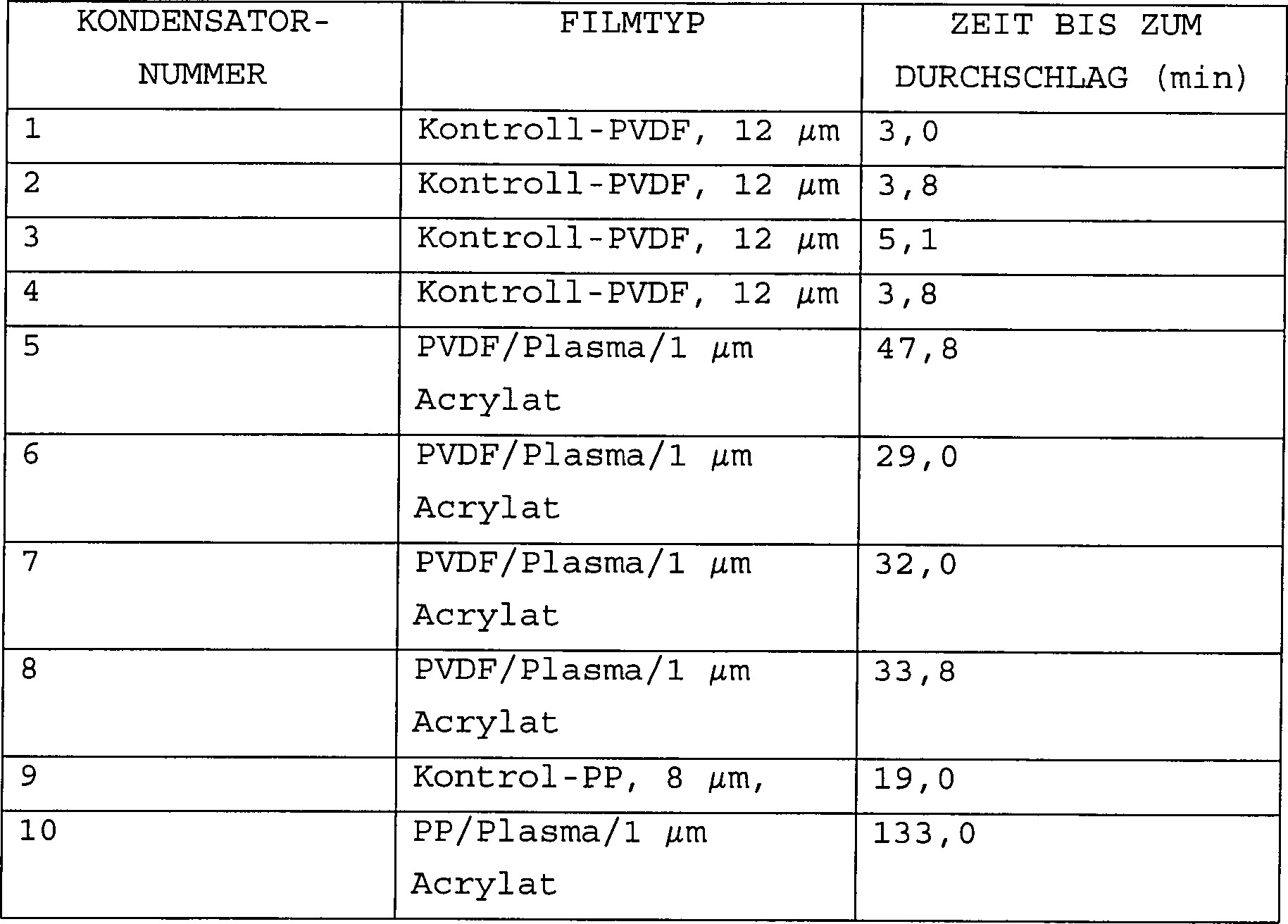
Wie aus Tabelle III ersichtlich ist, hatten die Hybridfilme etwa eine Größenordnung länger Zeit bis zum Versagen. Dies kann den Zuverlässigkeitsgrad der Kondensatoren signifikant erhöhen. Im Falle eines Kondensators des Pulstyps kann dies eine große Zahl zusätzlicher Pulse vor dem Versagen aufgrund von Koronaabbau repräsentieren.As from Table III, the hybrid films had about one Magnitude longer Time to failure. This can change the reliability of the capacitors increase significantly. In the case of a capacitor of the pulse type, this can be a large number additional Represent pulses before failure due to corona degradation.
5. Korrosionsbeständigkeit5. corrosion resistance
Kapazitätsverlust aufgrund von Elektrodenkorrosion ist der häufigste Versagensmechanismus bei metallisierten Kondensatoren. Die Korrosionsbeständigkeit von Aluminiumelektroden, die auf Kontroll-PP- und PP/Plasma/Acrylatfilmen abgelagert waren, wurde getestet. Die Korrosionsstabilität von mit Aluminium metallisierten PP- und PP/Plasma/Acrylatfilmen wurde durch Messung der Änderung des elektrischen Widerstands eines metallisierten Streifens von 12,7 cm × 2,5 cm (5 Inch mal 1 Inch) nach Exposition in einer Temperatur/Feuchtigkeit-Umgebung von 70°C/85% relative Luftfeuchtigkeit getestet. Die Streifen von 12,7 cm (5 Inch) wurden aus großen Materialrollen, die auch zur Herstellung von Kondensatoren voller Größe verwendet wurden, ausgeschnitten. Um sicherzustellen, dass bei jeder Messung (insbesondere wenn eine Korrosion der Elektrode beginnt) ein guter Elektrodenkontakt hergestellt wurde, wurde an beiden Enden des Streifens von 12,7 cm (5 Inch) eine dickere Aluminiumauflage abgelagert.loss of capacity due to electrode corrosion is the most common failure mechanism in metallized capacitors. The corrosion resistance of aluminum electrodes based on control PP and PP / plasma / acrylate films were deposited, was tested. The corrosion stability of with Aluminum metallized PP and PP / Plasma / Acrylic films were through Measuring the change of the electrical resistance of a metallized strip of 12.7 cm × 2.5 cm (5 inches by 1 inch) after exposure in a temperature / humidity environment from 70 ° C / 85% relative humidity tested. The strips of 12.7 cm (5 Inch) were made large Material rolls, which are also fuller for making capacitors Size used were cut out. To ensure that every measurement (especially when corrosion of the electrode starts) a good Electrode contact was made on both ends of the strip of 12.7 cm (5 inches) a thicker aluminum overlay deposited.
Die
Kontroll-PP- und Hybridfilme wurden aus der gleichen PP-Filmrolle
durch Plasmabehandlung und Acrylatbeschichtung der Hälfte der
Rolle (32 cm breit und 3048 m (10 000 Fuß) lang) und dann Metallisierung der
gesamten Rolle in einem einzigen Metallisierungsdurchgang produziert.
Die Oberflächeneigenschaften des Polymerfilms können bei der strukturellen und chemischen Stabilität der metallisierten Elektroden eine Hauptrolle spielen. Mehrere Untersuchungen wurden in der Vergangenheit durchgeführt, die zeigen, dass eine Oberflächenbehandlung der Polymerfilme vor der Metallisierung die Adhäsion und Korrosionsbeständigkeit der Aluminiumelektroden verbessert. Filmvernetzung, polare chemische Funktionalitäten und das Fehlen von Material mit niedrigem Molekulargewicht sind Parameter, die die Acrylatoberfläche begünstigen. Ferner wird ein PP-Film in der Regel vor der Metallisierung immer korona- oder flammbehandelt. Dies erfolgt in einer Linie mit dem Filmherstellungsprozess. Das anschließende Einwirken von Umgebungsbedingungen führt zu Feuchtigkeitsadsorption durch die durch das Behandlungsverfahren gebildeten Carboxyl-, Carbonyl- und Hydroxygruppen. Die adsorbierte Feuchtigkeit reagiert mit der Aluminiumablagerung und verschlechtert deren chemische Stabilität.The surface properties of the polymer film in the structural and chemical stability of the metallized electrodes play a major role. Several investigations have been made in the past carried out, that show a surface treatment the polymer films prior to metallization the adhesion and corrosion resistance the aluminum electrodes improved. Film crosslinking, polar chemical functionalities and the absence of low molecular weight material Parameters that the acrylate surface favor. Furthermore, a PP film is usually always before the metallization corona or flame treated. This is done in a line with the Film manufacturing process. Subsequent exposure to environmental conditions leads to Moisture adsorption by through the treatment process formed carboxyl, carbonyl and Hydroxy groups. The adsorbed moisture reacts with the aluminum deposit and worsens their chemical stability.
Die obigen Tests zeigen, dass die Acrylat-Hybridfilme eine Oberfläche mit einzigartigen Oberflächeneigenschaften aufweisen, die die chemische Beständigkeit von aufgedampften Aluminiummetallbeschichtungen erhöhen.The The above tests show that the hybrid acrylate films have a surface with unique surface properties that have the chemical resistance of vapor-deposited Increase aluminum metal coatings.
C. Bewertung von Hybridfilmen unter Verwendung von Kondensatoren voller GrößeC. Evaluation of hybrid films using capacitors of full size
Kondensatoren
voller Größe auf der
Basis eines Modells für
330 V Wechselstrom wurden unter Verwendung von Kontroll-PP-Filmen von 8 μm und eines
PP/Plasma/0,7 μm
Acrylat-Hybridfilms gefertigt. Das Acrylatpolymer wurde durch Elektronenstrahlhärtung eines
Monomerfilms von 70% Hexandioldiacry lat, 20% Isobornylacrylat und
10% Tripropylenglykoldiacrylat, der im Vakuum unter Verwendung der
in
Kondensatoren voller Größe wurden unter den gleichen Bedingungen wie die Filme kleiner Fläche gebaut und auf Elektrodenkorrosionsbeständigkeit bezüglich der Lebensdauer getestet. Statt der Ermittlung der Kapazitätsänderung wurde aufgrund des kurzen Testzeitraums die optische Dichte der Elektroden gemessen. Auf diese Weise konnte die Aluminiumoxidation detektiert werden, auch wenn die Elektrode leitete, was zu keinem Kapazitätsverlust führte. Die optische Dichte wurde zunächst an den Rollen, die zur Herstellung der Kondensatoren verwendet wurden, gemessen. Nach dem Test wurden die Kondensatoren abgewickelt und die optische Dichte des metallisierten Films am äußeren Teil der Rolle in einem fixierten Abstand vom Ende der Wicklung gemessen. Die Ergebnisse dieses Tests sind in Tabelle IV gezeigt. Vier Sätze von Kondensatoren wurden unter Verwendung von einem Kontroll-PP-Film und PP/Plasma/0,7 μm Acrylat-Hybridfilm, die mit dünnem Aluminium (optische Dichte 1,25 und 1,51, in Tabelle IV als (1) bezeichnet) und dickerem Aluminium (optische Dichte 1,68 und 1,76, in Tabelle IV als (2) bezeichnet) metallisiert waren, hergestellt.capacitors were full size built in the same conditions as the films of small area and on electrode corrosion resistance in terms of the lifetime tested. Instead of determining the capacity change was due to the short test period, the optical density of Electrodes measured. In this way, the aluminum oxidation could be detected, even if the electrode was conducting, leading to none loss of capacity led. The optical density was first on the rollers used to make the capacitors, measured. After the test, the capacitors were unwound and the optical density of the metallized film at the outer part of the roll in one fixed distance measured from the end of the winding. The results of this test are shown in Table IV. Four sets of capacitors were under Use of a control PP film and PP / plasma / 0.7 μm hybrid acrylate film coated with thin Aluminum (optical density 1.25 and 1.51, in Table IV as (1) and thicker aluminum (optical density 1.68 and 1.76, in Table IV as (2)).
TABELLE
IV ÄNDERUNGEN
DER OPTISCHEN DICHTE VON MIT ALUMINIUM METALLISIERTEN KONDENSATORFILMEN
VON PP- UND PP/PLASMA/0,7 μm
ACRYLATFILMEN AUFGRUND VON KORROSION IN EINER UMGEBUNG VON 70°C UND 85%
RELATIVER LUFTFEUCHTIGKEIT. 
Die
Ergebnisse in Tabelle IV zeigen, dass die Korrosionseigenschaften
von Kontroll-PP- und Acrylat-PP-Hybridfilmen bei Wicklung zu Kondensatorrollen
grundlegend die gleichen wie die der Filme kleiner Fläche sind
(Hybrid (1) ist das gleiche Filmmaterial, das in Prüflingen
kleiner Fläche
getestet wurde, siehe
Dies ist ein signifikanter Vorteil für die Hybridfilme. Die verbesserte Korrosionsbeständigkeit der metallisierten Elektroden ermöglicht die Verwendung dieses Produkts in Anwendungen, bei denen die Kondensatoren höherer Luftfeuchtigkeit und Temperatur ausgesetzt sind.This is a significant advantage for the hybrid films. The improved corrosion resistance of the metallized Electrodes enabled the use of this product in applications where the capacitors higher Humidity and temperature are exposed.
Ein Hochfrequenztest mit hohem Strom/niedriger Spannung wurde entwickelt, um die Strombelastbarkeit der Kondensatortermination zu bewerten. Der Strom durch die Kondensatoren wurde durch Variieren der Spannungsamplitude des Hochfrequenzsignals geändert. Nach dem Testen mehrerer Kondensatoren, um einen Satz von Bedingungen zu bestimmen, die die Kondensatortermination in einem messbaren Grade verschlechtern, wurden sowohl reine PP- als auch Hybridfilm kondensatoren getestet. Die in Tabelle V gezeigten Testdaten zeigen, dass Kondensatoren, die mit den Acrylat-PP-Hybridfilmdielektrika gebaut wurden, eine bessere Parameterstabilität als Schwestereinheiten, die mit Kontroll-PP-Film produziert wurden, besitzen.One Radio frequency test with high current / low voltage has been developed to evaluate the ampacity of the capacitor termination. The current through the capacitors was determined by varying the voltage amplitude changed the high frequency signal. After testing several capacitors, set a set of conditions to determine the capacitor termination in a measurable Grade deteriorated, were both pure PP and hybrid film capacitors tested. The test data shown in Table V show that capacitors, those with the acrylate-PP hybrid film dielectrics better parameter stability than sister units that were built with control PP movie were produced.
TABELLE
V VERLUSTFAKTOR
UND ESR VON KONDENSATOREN, DIE MIT PP-FILM UND ACRYLAT-PP-HYBRIDFILM GEBAUT
WURDEN. SIE WERDEN MIT 40 kHz VOR UND NACH DEM STARKSTROMTEST GETESTET. ANFANGSWERTE 
NACH
10 MIN 25 kHz 50 A SPITZENWERT BEI 60 V SPITZENWERT 
NACH
WEITEREN 5 MIN 25 kHz 75 A SPITZENWERT BEI 85 V SPITZENWERT 
Die Strombelastbarkeit der Kondensatoren voller Größe liegt in einer Linie mit den Strom- oder Energieverlust- bzw. -umwandlungs-Eigenschaften der metallisierten Filme kleiner Fläche (Tabelle IV). Ferner ist es interessant, festzustellen, dass die Hybridfilmkondensatoren voller Größe mit Hybrid(2)-Film (siehe Tabelle IV), der nicht die höchsten bzw. besten Energieverlusteigenschaften aufwies, gefertigt wurden. Dies legt nahe, dass mit optimierten Hybridfilmen gebaute Kondensatoren weitaus bessere Eigenschaften als die getesteten Kondensatoren aufweisen könnten.The Current carrying capacity of the full size capacitors is in line with the power or energy dissipation characteristics metallized films of small area (Table IV). It is further interesting to note that the hybrid film capacitors fuller Size with hybrid (2) movie (see Table IV), which does not have the highest or best energy loss properties showed, were manufactured. This suggests that with optimized Hybrid films built capacitors far better properties than the capacitors tested could have.
Kondensatoren
mit einer Kapazität
von 0,1 μF
wurden unter Verwendung von 19 μm
PP/Plasma/1,0 μm
Acrylat (in Tabelle VI als Hybrid A bezeichnet) und 12 μm PP/Plasma/1,0 μm Acrylat
(in Tabelle VI als Hybrid B bezeichnet) gefertigt. Diese Kondensatoren
wurden willkürlich
0,1 μF/2000
V Gleichstrom bzw. 0,1 μF/1200
V Gleichstrom zugeordnet. Das Acrylatpolymer wurde durch Elektronenstrahlhärtung eines
Monomerfilms von 70% Hexandioldiacrylat, 20% Isobornylacrylat und
10% Tripropylenglykoldiacrylat, der im Vakuum unter Verwendung der
in
Die Kondensatoren wurden mit kommerziellen Starkstromkondensatoren des Standes der Technik, die, obwohl sie die Bezeichnung 0,1 μF/1200 V hatten, ebenfalls ein PP-Dielektrikum von 19 μm und doppelt metallisierte Polyester(PET)-Filmelektroden verwendeten, um den Starkstrom zu führen, verglichen. Diese Kondensatoren hatten etwa die gleiche Größe wie die metallisierten Kondensatoren von 0,1 μF des Hybrid(A)films und mehr als das doppelte Volumen der Kondensatoren von 0,1 μF von Hybrid (B).The Capacitors were equipped with commercial power capacitors of the Prior art, which, although the designation 0.1 μF / 1200 V also had a PP dielectric of 19 microns and double metallized Polyester (PET) film electrodes used to power the power to lead, compared. These capacitors were about the same size as the metallized capacitors of 0.1 μF of the hybrid (A) film and more as the double volume of the capacitors of 0.1 μF of hybrid (B).
Alle Kondensatoren wurden unter Verwendung von Pulsen von 5000 V mit dV/dt von 1000 V/ns getestet. Die Kapazität und ESR wurden unter Verwendung einer konventionellen elektronischen Kapazitätsbrücke gemessen. Die Kapazität und ESR am Anfang werden mit der Kapazität und ESR nach dem Test in der folgenden Tabelle VI verglichen.All Capacitors were designed using 5000V pulses dV / dt of 1000 V / ns tested. The capacity and ESR were using a conventional electronic capacitance bridge measured. The capacity and ESR be in the beginning with the capacity and ESR after the test are compared in the following Table VI.
TABELLE
VI. SPANNUNGS- UND STROMBELASTUNGSVERGLEICH VON KOMMERZIELLEN PP-KONDENSATOREN
DES STANDES DER TECHNIK UND KONDENSATOREN, DIE MIT ACRYLATHYBRIDFILMEN
GEMÄß DER VORLIEGENDEN
ERFINDUNG GEBAUT WURDEN Kommerzieller
Kondensator 
Vorliegende
Erfindung, 19-μm-Hybrid
(0,1 μF/2000
V) 
Vorliegende
Erfindung, 12-μm-Hybrid
(0,1 μF/1200
V) 
Es ist ersichtlich, dass das 0,1 μF/2000 V Gleichstrom (Hybrid (A))-Modell das kommerzielle Modell gleicher Größe in einem sehr großen Maße übertrifft. Tatsächlich zeigen die Daten, dass alle außer zwei der kommerziellen Kondensatoren versagten, während keiner der durch das Verfahren der vorliegenden Erfindung hergestellten Kondensatoren einen signifikanten Abbau zeigte. Im Hinblick auf die gemäß der vorliegenden Erfindung hergestellten 0,1 μF/1200 V (Hybrid (B))-Kondensatoren (die weniger als die Hälfte der Größe der kommerziellen Kondensatoren besitzen) zeigen die Daten, dass, obwohl diese Kondensatoren abgebaut wurden, im Durchschnitt deren Eigenschaften besser als die kommerziellen Kondensatoren des Standes der Technik waren.It it can be seen that the 0.1 μF / 2000 V DC (hybrid (A)) model the same as the commercial model Size in one very big Measurements surpasses. Indeed show the data that all except two of the commercial capacitors failed while none that produced by the process of the present invention Capacitors showed a significant degradation. With regard according to the present Invention prepared 0.1 uF / 1200 V (hybrid (B)) capacitors (which are less than half of the Size of the commercial Possess capacitors) show the data that, although these capacitors on average, their properties were better than the commercial capacitors of the prior art were.
II. LEBENSMITTELVERPACKUNGSFOLIENII. FOOD PACKAGING FOILS
Bei Verpackungsanwendungen sind Sperrfolien zur Abtrennung von Produkten, wie Lebensmittel- und Elektronikkomponenten, von Umgebungen, die die Produktlebensdauer verringern, von besonderem Interesse. Derartige Sperrfilme können entweder unter Verwendung von Filmen, in denen die Barriere in den Film eingebaut ist, oder durch Applikation einer Beschichtung auf einen Film erreicht werden. Die Sperrbeschichtung kann entweder transparent sein, wobei sie beispielsweise Oxidmaterialien umfasst, oder opak oder semitransparent sein, wobei sie beispielsweise Metalle umfasst.at Packaging applications are barrier films for the separation of products, like food and electronic components, from environments that reduce product life, of particular interest. such Barrier films can either using films that contain the barrier in the film is installed, or by applying a coating to a Movie can be achieved. The barrier coating can be either transparent being, for example, comprising oxide materials, or opaque or semitransparent, for example comprising metals.
Die Verlängerung der Lagerungsdauer bei konkurrenzfähigen Kosten ist eine fortgesetzte Herausforderung für Filmproduzenten, Metallisierungsbetriebe und Laminatoren. Insbesondere fungiert für Lebensmittelanwendungen der metallisierte Film bzw. die metallisierte Folie als (a) Sauerstoff- und Feuchtigkeitsbarriere, um Lebensmittel frisch und knusprig halten zu können, (b) Lichtbarriere, um Ranzigwerden bei fetten Lebensmitteln zu verringern, und (c) Aromabarriere, um das ursprüngliche Aroma intakt zu halten. Weitere Anforderungen umfassen die Verarbeitbarkeit des metallisierten Films, Abriebbeständigkeit, mechanische Robustheit, Zuverlässigkeit und Kosten.The renewal storage time at competitive cost is an ongoing one Challenge for Film producers, Metallisierungsbetriebe and laminators. Especially acts for Food applications of the metallized film or the metallized Foil as (a) oxygen and moisture barrier to food fresh and crispy, (b) light barrier to reduce rancidity in fatty foods and (c) aroma barrier to keep the original flavor intact. Other requirements include the processability of the metallized Films, abrasion resistance, mechanical robustness, reliability and costs.
A. Opake metallisierte SperrfilmeA. Opaque metallized barrier films
Die Sperreigenschaften der metallisierten Aluminiumfilme hängen fast vollständig von der Integrität der metallisierten Aluminiumschicht ab. Die Qualität der metallisierten Schicht hängt von Defekten auf der Oberfläche des Polymerfilms ab. Große Defekte manifestieren sich hauptsächlich in der Form von Nadellöchern in der Metallisation, die mit dem optischen Mikroskop sichtbar sind. Nadellochdefekte sind üblicherweise zurückzuführen auf Teilchen auf der Filmoberfläche und Abrieb des Aluminiums an Filmfasern und anderen Oberflächenvorsprüngen, die durch Antioxidationsmittel und Gleitmittel verursacht sind. Diese Merkmale sprenkeln die Oberflächenlandschaft der Filme und sind für einen speziellen Filmlieferanten und ein Herstellungsverfahren charakteristisch. Obwohl die Zahl und Größe von Nadellöchern die Durchlässigkeit von Sauerstoff durch den Film dominieren kann, gibt es weitere Mikrostrukturdefekte, die die letztendlich mögliche Barriere für einen gegebenen Film bestimmen. Mikrostrukturdefekte können mehrere Formen aufweisen, die Mikronadellöcher, Mikrorisse und Mikrobereiche von sehr dünnem Aluminium umfassen. Diese Defekte können zurückverfolgt werden auf Eigenschaften des Substratfilms, die die Basisfilmchemie und das Herstellungsverfahren, Parameter, wie das Molekulargewicht des zur Herstellung des Films verwendeten Harzes, Additive für das Harz, Verfahrensbedingungen und Oberflächenbehandlung des Films, umfassen. Eine verbesserte Sperreigenschaft kann durch Minimierung der sowohl Groß- als auch Mikrostrukturdefektdichte auf der Filmoberfläche erreicht werden.The Barrier properties of metallized aluminum films almost hang Completely from the integrity of metallized aluminum layer. The quality of the metallized layer depends on Defects on the surface of the polymer film. Size Defects manifest themselves mainly in the form of pinholes in Metallization visible with the optical microscope. Pinhole defects are usually attributed to Particles on the film surface and attrition of the aluminum on film fibers and other surface protrusions caused by antioxidants and lubricants. These Features speckle the surface landscape the movies and are for a special film supplier and a manufacturing process characteristic. Although the number and size of pinholes is the permeability dominated by oxygen through the film, there are more microstructural defects, the ultimately possible Barrier for determine a given movie. Microstructural defects can be several Have shapes, the microwell holes, microcracks, and microareas of very thin Include aluminum. These defects can be traced to properties of the substrate film containing the base film chemistry and the method of preparation, Parameters, such as the molecular weight of the film used to make the film used resin, additives for the Resin, process conditions and surface treatment of the film. An improved lock feature can be achieved by minimizing both Big- as well as microstructure defect density on the film surface become.
Mehrere Materialien wurden zur Verwendung bei der Produktion von metallisierten Filmen hoher Sperreigenschaft untersucht. Ein Haupterfordernis ist, dass das Monomer und natürlich die Polymerbeschichtungen eine geringe Menge flüchtiger Komponenten haben müssen, um sicherzustellen, dass das Verpackungsmaterial keinen Geruch verursacht. Um Polymermaterialien zu qualifizieren, wurde ein Standard"aromatest" durchgeführt, und viele der Polymermaterialien, die getestet wurden, bestanden den Test. Eine desodorierte Version von Tripropylenglykoldiacrylat wurde willkürlich zur Durchführung von Sauerstoffsperrtests gewählt.Several Materials were for use in the production of metallized Films with high barrier properties. A key requirement is that the monomer and of course the polymer coatings must have a small amount of volatile components in order to ensure that the packaging material does not smell. In order to qualify polymer materials, an "aromatics" standard was performed, and many of the polymer materials that were tested passed the Test. A deodorized version of tripropylene glycol diacrylate was arbitrarily to carry out chosen by oxygen barrier tests.
Für opake Verpackungen mit hoher Sauerstoffsperreigenschaft (Kartoffelchipbeutel) ist der Industriestandard ein Polypropylenfilm (PP), der mit einer dünnen Schicht von Aluminium (Al) metallisiert ist. Die Barrierematerialentwicklung umfasste die folgenden Modelle von metallisierten PP- und Acrylathybridfilmen.For opaque High Oxygen Barrier Packaging (Potato Chips Bag) The industry standard is a polypropylene film (PP) that comes with a thin Layer of aluminum (Al) is metallized. The barrier material development included the following models of metallized PP and acrylic hybrid films.
1. PP/Plasma/Al/Acryl/Plasma1. PP / Plasma / Al / Acrylic / Plasma
Das
Acrylatpolymer wurde durch Elektronenstrahlhärtung eines Tripropylenglykoldiacrylatmonomerfilms,
der im Vakuum unter Verwendung der in
Die
Plasmabehandlungsfunktionalisierung des PP-Films führte zu
höheren
Keimbildungsraten des Aluminiums und einer feineren Kristallstruktur.
Die Bildung feinerer Aluminiumkristallite wurde unter Verwendung
von Röntgenbeugungs(XRD)analyse
festgestellt. Speziell wurden die metallisierten Filme unter Verwendung
eines Scintag XRD-Systems getestet, das zeigte, dass der 2,344 cps-Peak
von Aluminium für
den plasmabehandelten Film mindestens dreimal weniger intensiv und
etwa zweimal so breit wie der nichtbehandelte metallisierte Film
war. Auch zeigten Transmissionselektronenmikroskopie(TEM)- und Elektronenbeugungsanalyse,
die auf einem Hitachi TEM durchgeführt wurden, dass die Kristalle
in dem auf dem plasmabehandelten PP-Film abgelagerten Aluminium
viel kleiner mit sehr breiten Beugungsringen (bei Vergleich mit
dem auf Kontroll-PP abgelagertem Aluminium) waren. Die feineren
Aluminiumkristallite führen
zu einem flexibleren Metallfilm, der einer Mikrorissbildung während des
Reckens widersteht. Dies wurde durch Überwachung des elektrischen
Widerstands eines metallisierten Films, wäh rend der Film mit einer festen
Geschwindigkeit gedehnt wurde, unter Verwendung eines computergesteuerten
Systems ermittelt. Bei einem metallisierten Film führt Mikrorissbildung
der Metallschicht zu einer Zunahme von deren elektrischem Widerstand.
2. PP/Plasma/Acryl/Al2. PP / Plasma / Acrylic / Al
Das
Acrylatpolymer wurde durch Elektronenstrahlhärtung eines Tripropylenglykoldiacrylatmonomerfilms,
der im Vakuum unter Verwendung der in
Ferner enthäkelt die Oberfläche des PP-Films Material mit niedrigem Molekulargewicht, das aus PP, abgebautem PP und dem Film während der Herstellung zugesetzten Gleitmitteln besteht. Es wurde entdeckt, dass diese Spezies mit niedrigem Molekulargewicht erneut fließen, wenn sie der durch die Verdampfungsquellen und die Kondensation der Aluminiumablagerung erzeugten Wärme ausgesetzt werden. Das erneute Fließen verhindert die Keimbildung von Aluminiumatomen auf der Oberfläche dieser Stellen, wodurch Nadellöcher erzeugt werden, die die Feuchtigkeits- und Sauerstoffsperreigenschaften verschlechtern. Diese Wirkung wird eliminiert oder minimiert, wenn das Hochtemperaturacrylatpolymer auf der PP-Oberfläche abgelagert und dann metallisiert wird.Further enthäkelt the surface of PP film low molecular weight material that is degraded from PP PP and the movie while the production of added lubricants. It was discovered that these low molecular weight species will flow again if they are caused by the evaporation sources and the condensation of the aluminum deposit generated heat get abandoned. The re-flow prevents nucleation of aluminum atoms on the surface of these sites, thereby Pinholes generated which are the moisture and oxygen barrier properties deteriorate. This effect is eliminated or minimized when the high temperature acrylate polymer is deposited on the PP surface and then metallized.
3. PP/Plasma//Acryl/Al/Acryl/Plasma3. PP / Plasma // Acrylic / Al / Acrylic / Plasma
Das
Acrylatpolymer wurde durch Elektronenstrahlhärtung eines Tripropylenglykoldiacrylatmonomerfilms,
der im Vakuum unter Verwendung der in
Um die Hybridfilmproduktion wirtschaftlich attraktiver zu machen, können schlechtere Qualitäten von PP-Filmen (niedrigere Kosten), die bei Metallisierung Sauerstoffdurchlässigkeitsraten (OTR) im Bereich von 3 bis 10 besitzen, gegenüber Filmen höherer Qualität, die OTRs im Bereich von 1 bis 3 besitzen, verwendet werden. Die Daten in der folgenden Tabelle VII zeigen, dass die OTR von Kontrollfilmen (PP/Al) von 6,17 bis auf 0,07 unter Verwendung der im vorhergehenden beschriebenen Hybridfilmmodelle verringert werden können. Alle hier berichteten OTR- und MVTR-Barrieremessungen wurden von einem Dritten unter Verwendung kommer zieller Geräte durchgeführt. Unter Berücksichtigung, dass die Hybridfilme in den gleichen Metallisierungseinrichtungen, in denen die Kontrollfilme hergestellt wurden, und mit geringen zusätzlichen Kosten produziert werden können, stellen die OTR-Werte der Hybridfilme eine nicht vorhersehbare Höhe der Verbesserung dar und sie sind im Handel erhältlichen Filmen bzw. Folien weitaus überlegen.Around making hybrid film production more economically attractive can be worse qualities of PP films (lower cost), which in metallization oxygen transmission rates (OTRs) range from 3 to 10, compared to higher quality films, the OTRs in the range of 1 to 3, can be used. The data in Table VII below shows that the OTR of control films (PP / Al) from 6.17 to 0.07 using the above described hybrid film models can be reduced. All OTR and MVTR barrier measurements reported here were from a Third party using commercial equipment. Considering, that the hybrid films in the same metallization, in which the control films were produced, and with low additional Costs can be produced The OTR values of hybrid films provide an unpredictable level of improvement and they are commercially available Far superior to films or foils.
TABELLE
VII. SAUERSTOFFDURCHLÄSSIGKEITSRATE
(OTR) VON METALLISIERTEN KONTROLL-PP(PP/Al)- UND ACRYLAT/PP-HYBRIDFILMEN 
Es ist anzumerken, dass das Polypropylen für den Fall, dass das Acrylatpolymer direkt auf dem Polypropylen abgelagert wurde (die obigen Konfigurationen 2 und 3), plasmabehandelt wurde. Es wurde ermittelt, dass die Plasmabehandlung aus zwei Gründen vorteilhaft ist, (a) sie entfernt adsorbierte Luft und Feuchtigkeit von der Oberfläche des PP-Films, was den Vernetzungsgrad auf der PP/Acrylat-Grenzfläche verstärkt, und (b) sie funktionalisiert den PP-Film, was eine Benetzung durch das Acrylatmonomer ermöglicht. Mehrere Gase wurden für den Plasmabehandlungsvorgang verwendet, wobei diese Ar, N2, O2, Ne, CO2 und Gemische derselben umfassten. Ar und N2 in einem Gemisch im Verhältnis 10%/90% ergaben ein sehr effektives Gemisch, was durch Benetzung und Gleichförmigkeit der Polymerschicht ermittelt wurde, und dies ergaben auch Gemische mit 5% O2. Ein weiteres effektives Gasgemisch umfasst 9,9% Ne und 0,1% Ar und ein Gemisch desselben mit 10% N2 oder 5% O2 oder 5% CO2. Die langlebigen metastabilen Zustände im Ne-Atom verstärken den Ionisierungszustand des Gemischs und erhöhen den Ionisationsstrom und die Oberflächenbehandlung signifikant. Ein weiteres effektives Gemisch ist 96% CF4 und 4% O2.It should be noted that in the case where the acrylate polymer was deposited directly on the polypropylene (the above configurations 2 and 3), the polypropylene was plasma-treated. It has been found that the plasma treatment is advantageous for two reasons: (a) it removes adsorbed air and moisture from the surface of the PP film, which enhances the degree of crosslinking on the PP / acrylate interface, and (b) functionalizes the PP Film, which allows wetting by the acrylate monomer. Several gases were used for the plasma treatment process, including Ar, N 2 , O 2 , Ne, CO 2, and mixtures thereof. Ar and N 2 in a 10% / 90% mixture gave a very effective mixture, as determined by wetting and uniformity of the polymer layer, and this also gave mixtures with 5% O 2 . Another effective gas mixture comprises 9.9% Ne and 0.1% Ar and a mixture thereof with 10% N 2 or 5% O 2 or 5% CO 2 . The long-lived metastable states in the Ne atom enhance the ionization state of the mixture and significantly increase the ionization current and surface treatment. Another effective mixture is 96% CF 4 and 4% O 2 .
Es wurde auch ermittelt, dass sich zu Zeitpunkten, nachdem der Hybridfilm zu einer Rolle aufgewickelt war, ein bestimmter Grad an "Blockbildung" oder Klebrigkeit entwickelte, da die Rückseite des Polypropylenfilms auf dieser eine weiche Copolymerschicht abgelagert hat, die zur thermischen Versiegelung des Kunststoffbeutels verwendet wird. Die Klebrigkeit war das Ergebnis der kombinierten Wirkung eines partiellen Härtens auf der Oberfläche der Acrylatbeschichtung und einer elektrostatischen Aufladung (Elektronen), die in tiefen und flachen Potentialvertiefungen in der Acrylatbeschichtung gefangen sein können.It It was also found that at times after the hybrid film wound into a roll, a certain degree of "blocking" or stickiness developed because the back of the polypropylene film deposited on this one soft copolymer layer has, which used for thermal sealing of the plastic bag becomes. The stickiness was the result of the combined effect a partial hardening on the surface the acrylate coating and an electrostatic charge (electrons), in deep and shallow potential wells in the acrylate coating can be caught.
Es wurde ermittelt, dass die Blockbildung durch Hinzufügen einer zweiten Vernetzungs- und Entladungsstation nach der Bildung des Acrylatpolymers in der ersten Station eliminiert werden konnte. Die zweite Vernetzungsstation kann ein weiterer Elektronenstrahl niedrigerer Energie oder eine Plasmabehandlungsstation sein. Ein Elektronenstrahl mit einer Energie von 600 bis 1200 eV wurde für eine weitere Oberflächenhärtung und Entladung der Oberfläche des Acrylatpolymers verwendet. Bei dieser Spannungshöhe besitzen die meisten Polymermaterialien einen Sekundärelektronenemissionskoeffizienten, der höher als 1,0 ist, was daher zu einer Oberflächenentladung führt, da für jedes auftreffende Elektron mehr als ein Elektron von der Oberfläche emittiert werden. Eine Plasmabehandlungsstation erreicht das gleiche Ergebnis, obwohl der Mechanismus unterschiedlich ist. Die Strahlung bei einer Plasmaentladung umfasst Ionen und UV-Strahlung. Die UV-Strahlung umfasst sehr ener giereiche (15 eV) Vakuum-UV-Photonen, die die Oberflächenvernetzung verstärken, während die Ionen die Entladung der Filmoberfläche unterstützen.It it was determined that the block formation by adding a second crosslinking and discharge station after the formation of the Acrylate polymer could be eliminated in the first station. The second crosslinking station can be another electron beam lower energy or a plasma treatment station. One Electron beam with an energy of 600 to 1200 eV was used for another Surface hardening and Discharge of the surface of the acrylate polymer. Own at this voltage level most polymer materials have a secondary electron emission coefficient, the higher is 1.0, which therefore results in a surface discharge since for each incident electron emits more than one electron from the surface become. A plasma treatment station achieves the same result, although the mechanism is different. The radiation at one Plasma discharge includes ions and UV radiation. The UV radiation includes very high energy (15 eV) vacuum UV photons, which cause surface crosslinking reinforce while the Ions support the discharge of the film surface.
Ein alternatives Verfahren zur Verhinderung einer Blockbildung des Films in der Rolle ist die Verwendung von Monomerformulierungen, die kleine Mengen von Additiven, wie Monoacrylatmonomere, die nicht vollständig vernetzen können oder partiell leitend sind, umfassen. Dies führt zur Bildung einer "gleitfähigen" und/oder antistatischen Acrylatoberfläche, die eine Blockbildung und die Bildung einer statischen Aufladung hemmt.One alternative method of preventing blocking of the film in the role is the use of monomer formulations, the small ones Levels of additives such as monoacrylate monomers that do not fully crosslink can or partially conductive. This leads to the formation of a "lubricious" and / or antistatic acrylic surface, which inhibits block formation and the formation of a static charge.
B. Transparente keramikbeschichtete SperrfilmeB. Transparent ceramic coated barrier films
Umweltbeschränkungen führen zum Austausch bestimmter chlorhaltiger Polymerfilme mit hohen Sperreigenschaften durch Polyesterfilme, die mit transparenten Barriereschichten anorganischer Materialien, wie Aluminiumoxid und Siliciumoxide (SiOx, wobei x = 1 bis 2), beschichtet sind.Environmental constraints result in replacement of certain high-barrier chlorine-containing polymer films by polyester films coated with transparent barrier layers of inorganic materials such as alumina and silicon oxides (SiO x where x = 1 to 2).
Einige Lebensmittelhersteller akzeptierten nur langsam die kostenaufwändigeren beschichteten transparenten Sperrfilme aufgrund des höheren Preises des Polyesterfilms, der zur Produktion transparenter Beschichtungen mit hohen Sperreigenschaften notwendig zu sein scheint. Hierfür wurden mehrere Versuche zur Produktion einer kostengünstigeren transparenten Barriere unter Verwendung von Polypropylen(PP)substratfilmen unternommen. Diese Arbeit zeigte, dass die PP-Filme mit niedrigem Schmelzpunkt allgemein ein schlechtes Substrat für die Ablagerung der anorganischen Beschichtungen mit höherem Schmelzpunkt sind. Daher verwenden keramikbeschichtete transparente Sperrfilme, die derzeit auf dem Markt sind, einen Polyesterfilm als Substrat, das gegenüber PP höherwertige thermomechanische Eigenschaf ten hat.Some food manufacturers have been slow to accept the more costly coated transparent barrier films because of the higher price of the polyester film that appears to be needed to produce transparent coatings with high barrier properties. For this purpose, several experiments were Production of a lower cost transparent barrier made using polypropylene (PP) substrate films. This work showed that the low melting point PP films are generally a poor substrate for deposition of the higher melting point inorganic coatings. Therefore, ceramic-coated transparent barrier films which are currently on the market use a polyester film as a substrate which has higher thermo-mechanical properties than PP.
Die vorliegende Erfindung betrifft die kostengünstige Produktion von metallisierten Filmen mit hohen Sperreigenschaften sowie transparenten PP-Filmen mit hohen Sperreigenschaften unter Verwendung einer Kombination von Vakuumpolymerbeschichtung und Oberflächenmodifikation durch eine Plasmabehandlung. Ein PP-Film wurde unter Verwendung eines 90% N2/10% Ar-Gasgemischs plasmabehandelt und ein Acrylatmonomer mit geringem Geruch wurde abgelagert und mit Elektronenstrahlung vernetzt. Die Beschleunigungsspannung beträgt typischerweise 10 bis 12 keV für eine Acrylatbeschichtung von 1,0 μm. Der Strom (oder die Zahl der Elektronen) variiert mit der Bahngeschwindigkeit. Für eine ein Fuß breite Bahn, die sich mit 30,48 bis 61 m/min (100 bis 200 ft/min) bewegt, wurde ein Strom von 5 bis 10 mA verwendet.The present invention relates to the low cost production of high barrier metallized films as well as high barrier PP transparent films utilizing a combination of vacuum polymer coating and surface modification by plasma treatment. A PP film was plasma treated using a 90% N 2 /10% Ar gas mixture, and a low odor acrylate monomer was deposited and crosslinked with electron beam radiation. The acceleration voltage is typically 10 to 12 keV for an acrylate coating of 1.0 μm. The current (or the number of electrons) varies with the web speed. For a one foot wide web moving at 30.48 to 61 m / min (100 to 200 ft / min), a current of 5 to 10 mA was used.
Die bei der Durchführung der vorliegenden Erfindung verwendeten transparenten Filme umfassen Aluminiumoxid, Siliciumoxide (SiOx, wobei x = 1 bis 2), Tantaloxid, Aluminiumnitrid, Titannitrid, Siliciumnitrid, Siliciumoxynitrid, Zinkoxid, Indiumoxid und Indium-zinn-oxid. Die Dicke der Keramikbeschichtung kann zur Verwendung als Sperrschicht im Bereich von 5 bis 100 nm liegen. Vorzugsweise werden die besten Sperreigenschaften im unteren Teil des Dickebereichs erhalten. Die Keramikbeschichtung kann durch Elektronenstrahlverdampfung abgelagert werden.The transparent films used in the practice of the present invention include alumina, silicas (SiO x , where x = 1 to 2), tantalum oxide, aluminum nitride, titanium nitride, silicon nitride, silicon oxynitride, zinc oxide, indium oxide, and indium tin oxide. The thickness of the ceramic coating may be in the range of 5 to 100 nm for use as a barrier layer. Preferably, the best barrier properties are obtained in the lower part of the thickness range. The ceramic coating can be deposited by electron beam evaporation.
Zwei Arten transparenter Sperrfilme wurden produziert, eine unter Verwendung eines dünnen anorganischen Films von SiOx, wobei x = 1 bis 2, und von Al2O3. Der SiOx-Film wurde unter Verwendung einer Plasmaablagerung aus einem Silangasgemisch abgelagert, und der Al2O3-Film wurde unter Verwendung von Elektronenstrahlverdampfung abgelagert. Bei diesem Experi ment bestand die Aufgabe darin, zu schauen, ob der thermomechanisch höherwertige Acrylathybridfilm verbesserte Sperreigenschaften hatte, statt die Barriereeigenschaften auf ein Minimum zu optimieren. Die in Tabelle VIII angegebenen Ergebnisse zeigen, dass die Sauerstoff- und Feuchtigkeitssperreigenschaften des transparenten PP/Plasma/Acrylat/Keramikfilms dem Kontroll-PP/Keramikfilm überlegen sind.Two types of transparent barrier films were produced, one using a thin inorganic film of SiO x , where x = 1 to 2, and Al 2 O 3 . The SiO x film was deposited from a silane gas mixture using plasma deposition, and the Al 2 O 3 film was deposited using electron beam evaporation. In this experiment, the task was to see if the thermo-mechanically higher acrylate hybrid film had improved barrier properties, rather than minimizing barrier properties. The results given in Table VIII show that the oxygen and moisture barrier properties of the transparent PP / plasma / acrylate / ceramic film are superior to the control PP / ceramic film.
TABELLE
VIII. SAUERSTOFF(OTR)- UND FEUCHTIGKEITS(MVTR)DURCHLÄSSIGKEITSRATE
VON KONTROLL-PP/KERAMIK-
UND PP/PLASMA/ACRYLAT/KERAMIKHYBRIDFILMEN 
Bei
Verpackungsanwendungen ist es wichtig, dass die Sperreigenschaften
eines Films während
des Verfahrens der Verarbeitung des Films zu einem Beutel beibehalten
werden. Dieses Verfahren setzt den Film einer Dehnung und Reckung
aus, wenn der Film über
eine Formungsmanschette gezogen wird, die den ebenen Film dazu bringt,
dass er sich einer zylindrischen Öffnung anpasst, die zunächst an
der Seite, dann am Boden und auf der Oberseite nach dem automatischen
Einführen
von Lebensmitteln in den Beutel versiegelt wird. Wenn ein konventioneller
metallisierter PP-Film gedehnt wird, kann die Aluminiumschicht leicht
reißen, was
zum Verlust der Barriere führt.
Da Sperreigenschaften als Funktion der Dehnung schwierig zu messen sind,
wurde das Reißen
des Aluminiums als Funktion der Dehnung indirekt durch Messung des
Widerstands des Aluminiums ermittelt.
Eine
weitere Untersuchung der Struktur des Aluminiums unter Verwendung
von Röntgenbeugungsanalyse,
Transmissionselektronenmikroskopie und Elektronenbeugungsanalyse
zeigt, dass das auf der Kontroll-PP-Oberfläche gebildete Aluminium große Kristalle
aufweist, während
in dem Hybridfilm abgelagertes Aluminium eine viel feinere Kristallstruktur
aufweist. Eine derartige Kristallstruktur in Kombination mit hervorragender
Aluminiumhaftung an der nitridierten PP-Oberfläche und der Schutzacrylatbeschichtung
minimiert die Bildung von Mikrorissen und bewahrt die ursprünglichen
Sperreigenschaften des Films. Mehrere Verpackungsuntersuchungen,
die von einem leitenden Hersteller von Snacklebensmitteln durchgeführt wurden,
zeigten diese Beutel, die mit einer Monobahn aus PP/Plasma/Aluminium/Acrylat
produziert wurden. Das Acrylatpolymer wurde durch Elektronenstrahlhärtung eines
Tripropylenglykoldiacrylatmonomerfilms, der im Vakuum unter Verwendung
der in
Der Hybridfilm behielt niedrige MVTR und OTR bei, während der Kontroll-PP/Al-Film eine Zunahme um etwa eine Größenordnung zeigen kann. Die Tabelle IX zeigt OTR- und MVTR-Daten nach der Filmproduktion, nach Bedrucken und nach der Beutelproduktion.Of the Hybrid film maintained low MVTR and OTR while controlling PP / Al film an increase of about one order of magnitude can show. Table IX shows OTR and MVTR data after film production Printing and after bag production.
TABELLE
IX. SAUERSTOFF(OTR)- UND FEUCHTIGKEITS(MVTR)-DURCHLÄSSIGKEITSRATE VON PP/PLASMA/ALUMINIUM/ACRYLAT/PLASMA-HYBRIDFILMEN
IN VERSCHIEDENEN PRODUKTIONSSTUFEN EINES SNACKLEBENSMITTELBEUTELS 
III. FILME FÜR DRUCKANWENDUNGENIII. FILMS FOR PRINTING APPLICATIONS
In
der obigen Beschreibung von Verpackungsanwendungen kann der PP/Plasma/Metall/Acrylat/Plasma-Hybridfilm
direkt nach der Produktion ohne spezielle Vorbereitungen bedruckt
werden. Die Druckindustrie verwendet einen breiten Bereich von Druckfarben,
die drei Hauptkategorien: wasserbasierte, lösemittel(öl)basierte und 100% Feststoffe,
umfassen. Obwohl diese Druckfarben für feuchte unterschiedliche
Oberflächenarten
formuliert sind, werden Oberflächen
häufig
so formuliert, dass sie durch ein spezielles Druckfarbenverfahren
und -gerät,
das ein Lebensmittelhersteller am Ort hat, benetzt bzw. befeuchtet
werden. Die Acrylathybridfilme können
so gestaltet werden, dass sie von verschiedenen Druckfar benchemien
benetzt werden. Die hydrophoben/hydrophilen und oleophoben/oleophilen
Oberflächenbenetzungseigenschaften
wurden unter Verwendung der in Tabelle X gezeigten Lösungen ermittelt.
Ein Tropfen von jeder der Lösungen
in Tabelle X wurde auf der Oberfläche eines Acrylatpolymers,
die durch Elektronenstrahlhärtung
des Acrylatmonomers erhalten wurde, abgelagert. Wenn der Flüssigkeitstropfen
einer speziellen Zusammensetzung (1–6) die Oberfläche innerhalb
des angegebenen Zeitraums (siehe Fußnoten in Tabelle X) nicht
benetzt, wird die Oberfläche
als für diese
Flüssigkeit
phob betrachtet. TABELLE
X. FÜR
BENETZUNGSTESTS VERWENDETE LÖSUNGSCHEMIE,
WOBEI DIE ZAHL "1" AM STÄRKSTEN PHIL
UND DIE ZAHL "6" AM STÄRKSTEN PHOB
IST 

Etwa
100 verschiedene Acrylatformulierungen wurden produziert und auf
Basisbenetzungseigenschaften getestet (siehe die Liste unter "Kondensatoren" oben). Die Ergebnisse
in 
Zusätzlich zu Druckanwendungen kann die Oberflächenbenetzungsfunktionalisierung der PP/Acrylatfilme bei anderen Anwendungen verwendbar sein, bei denen eine Oberflächenbenetzung oder ein Fehlen derselben wichtig ist. Beispielsweise kann eine teflonähnliche Oberfläche, die Wasser abstößt, viele großtechnische und kommerzielle Anwendungen haben. Eine oleophile Oberfläche könnte bei Film/Folienkondensatoranwendungen verwendet werden, bei denen die aufgewickelten Rollen mit einer dielektrischen Flüssigkeit auf Ölbasis sorgfältig getränkt werden müssen.In addition to Printing applications may include surface wetting functionalization PP / acrylate films may be useful in other applications which a surface wetting or a lack thereof is important. For example, a similar to Teflon Surface, the water repels, many large-scale and have commercial applications. An oleophilic surface could be added Film / film capacitor applications are used in which the wound rolls with a dielectric liquid oil-based careful soaked Need to become.
IV. MAGNETBÄNDERIV. MAGNETIC BANDS
Die Notwendigkeit für Speichermedien zunehmend höherer Dichte, die breite Verwendung von Videobändern eines engen Formats und die Entwicklung digitaler Audio- und Videobandlaufwerke führen zu einer Aufzeichnung mit kürzerer Wellenlänge, die eine höhere Datenspeicherung pro Einheitslänge eines Bandes ermöglicht. Derartige Aufzeichnungsbänder verwenden eine dünne Metallmagnetbeschichtung, die durch Metallaufdampf-, -sputter- und -plattierungstechniken erhalten werden kann. Dieser Ansatz eliminiert das Polymerbindemittel, das bei herkömmlichen Magnetbeschichtungen verwendet wird, was zu ferromagnetischen Schichten mit höherer Sättigungsmagnetisierung führt, was für höhere Speicherdichten günstig ist.The Need for Storage media of increasingly higher density, the wide use of videotapes a tight format and the development of digital audio and video tape drives to lead to a recording with shorter Wavelength, the one higher Data storage per unit length a volume allows. Such recording tapes use a thin one Metal magnetic coating produced by metal vapor, sputtering and Plating techniques can be obtained. This approach eliminates the polymer binder used in conventional magnetic coatings resulting in ferromagnetic layers with higher saturation magnetization leads, what kind of higher Storage densities favorable is.
Wenn eine Aufzeichnung mit kurzer Wellenlänge verwendet wird, ist der Ausfall oder Verlust von Information für einen gegebenen Abstand zwischen dem Aufzeichnungsmedium und dem Magnetkopf viel höher. Der Abstandsverlust wird durch die Formel 54,6d/w dargestellt, wobei d der Abstand von Band zu Kopf ist und w die Aufzeichnungswellenlänge ist. Daher erfolgt, wenn die Oberfläche des Magnetmediums oder auch die entgegengesetzte Seite rau sind, ein Verlust an Information, wenn das Band vor dem Kopf läuft. Aus diesem Grund sind Filme, die für metallisierte Magnetbänder verwendet werden, sehr kostenaufwändig, da die Oberflächenrauheit von sowohl der Vorder- als auch der Rückseite genau kontrolliert sein müssen, um einen geringen Rauheitsgrad sicherzustellen. Es ist anzumerken, dass, wenn die Rauheit der Rückseite zu niedrig ist, das Band dann binden und geschädigt werden kann.If a short wavelength record is used is the Failure or loss of information for a given distance between the recording medium and the magnetic head much higher. Of the Distance loss is represented by the formula 54.6d / w where d is the distance from tape to head and w is the recording wavelength. Therefore, when the surface occurs the magnetic medium or the opposite side are rough, a loss of information when the tape is in front of the head. Out This is why films are made for metallized magnetic tapes used, very expensive, since the surface roughness from both the front and the back accurately controlled have to be to ensure a low degree of roughness. It should be noted that if the roughness of the back too low, the band can then bind and be damaged.
Ein weiteres Problem mit dünnen Metallbändern ist eine Schädigung des Magnetbandes aufgrund von Abriebbeständigkeit und Umgebungskorrosion. Bandhersteller entwickelten verschiedene Wege zum Umgang mit diesen Beschränkungen. Strahlungshärtende Materialien werden üblicherweise zur Beschichtung von sowohl der Vorder- als auch der Rückseite des Substratbands verwendet und häufig werden anorganische Additive für gesteuerte Rauheit und antistatische Eigenschaften auf der Rückseitenbeschichtung verwendet (US-Patente 5 068 145, 4 679 340, 4 720 421, 4 781 965, 4 812 351, 4 67 083 und 5 085 911). Die bestehenden Verfahren zur Applikation der strahlungshärtenden Beschichtungen verwenden herkömmliche Applikationsverfahren (Walzenbeschichtung, Gießen und auf Lösungsbasis) unter atmosphärischen Bedingungen und zur Härtung werden UV- oder Elektronenstrahlung verwendet, wobei diese an Luft oder in einer Stickstoffumgebung durchgeführt wird.One another problem with thin metal strips is a damage of the magnetic tape due to abrasion resistance and environmental corrosion. Tape manufacturers have developed different ways of dealing with these Restrictions. Radiation curing Materials are becoming common for coating both the front and the back Of the substrate tape used and often become inorganic additives for controlled Roughness and antistatic properties on the backside coating used (US patents 5 068 145, 4 679 340, 4 720 421, 4 781 965, 4 812 351, 4 67 083 and 5,085,911). The existing procedures for the application of radiation-curing Coatings use conventional Application method (roller coating, casting and solution-based) under atmospheric Conditions and for curing UV or electron radiation are used, these in air or in a nitrogen environment.
In
der vorliegenden Erfindung werden Acrylatbeschichtungen aus der
Dampfphase im Vakuum abgelagert, was dünnere, von Nadellöchern freie
und gleichförmigere
Beschichtungen in einer Linie mit der Ablagerung der magnetischen
Beschichtung ermöglicht.
Auf einer Oberfläche
eines Polyesterfilms abgelagerte Acrylatpolymerfilme können Oberflächenunregelmäßigkeiten
um ein bis zwei Größenordnungen
in Abhängigkeit
von der Dicke der Acrylatschicht einebnen. Beispielsweise verringert
eine Acrylatbeschichtung von 2,0 μm auf
einer Oberfläche
mit rauen Vorsprüngen
von 400 nm die durchschnittliche Oberflächenrauheit auf weniger als
50 nm. Das Acrylatpolymer wurde durch Elektronenstrahlhärtung eines
Hexandioldiacrylatmonomerfilms, der im Vakuum unter Verwendung der
in
Wie im vorhergehenden angegeben, wird eine Oberfläche mit einer kontrollierten Rauheit auf der Rückseite des Magnetbands häufig gewünscht, um die Reibung über Walzen zu minimieren. Ein Hybridfilm mit einer kontrollierten Mikrorauheit wurde auf die folgende Weise produziert. Nach der Ablagerung eines strahlungshärtenden Monomers wird ein Elektronenstrahl zur Polymerisation des dünnen Monomerfilms verwendet. Für eine Filmdicke von 1,0 μm kann ein Strahl mit einer Beschleunigungsspannung von etwa 8 bis 12 keV verwendet werden. Wenn die Strahlspannung beträchtlich verringert wird, wird die Eindringtiefe der Elektronen proportional verringert. Beispielsweise härtet eine Beschleunigungsspannung von 600 bis 1000 eV die Oberfläche des Acrylatfilms, wodurch eine dünne Haut geschaffen wird. Die bei der exothermen Polymerisationsreaktion produzierte Wärme und die Schrumpfung des Acrylatfilms während der Polymerisation bewirken eine Faltenbildung der Haut in einer sehr kontrollierten Weise.As stated above, a surface with a controlled Roughness on the back of magnetic tape often desired about the friction over Minimize rolling. A hybrid film with a controlled microroughness was produced in the following way. After the deposition of a radiation curing Monomer becomes an electron beam to polymerize the thin monomer film used. For a film thickness of 1.0 μm can be a beam with an acceleration voltage of about 8 to 12 keV are used. When the beam voltage is considerable is decreased, the penetration depth of the electrons becomes proportional reduced. For example, hardens an acceleration voltage of 600 to 1000 eV the surface of Acrylic film, creating a thin Skin is created. The in the exothermic polymerization reaction produced heat and cause the shrinkage of the acrylate film during the polymerization Wrinkling of the skin in a very controlled manner.
Ein
Querschnitt der gefalteten Oberfläche
Die
verringerte Spannung kann durch Platzieren einer kleineren Elektronenstrahlkanone
Die
in
V. OPTISCHE FILTERV. OPTICAL FILTERS
Polymerfilme mit optischen Effekten, wie Farbverschiebung, und holographischen Bildern werden bei verschiedenen Anwendungen verwendet, die Einwickelfolien und fälschungssichere und vor einer Nachahmung schützende Medaillons umfassen. Zwei derartige Acrylathybridfilme wurden in einem einstufigen kostengünstigen Herstellungsverfahren produziert.
- (A) Der oben
beschriebene faltige Film erzeugt bei Metallisierung nach der zweiten
Elektronenstrahlhärtung (
7B ) leuchtende Farbverschiebungsreflexionen, wenn die Faltengröße für eine Interferenz mit dem Umgebungslicht klein genug ist. Obwohl in dieser Arbeit nur ein gleichförmiges Interferenzmuster über die Filmoberfläche produziert wurde, können Farbverschiebungsbilder durch Bemusterung der Faltenfläche62b und durch Variation der Faltengröße innerhalb eines Bildes produziert werden. Dies kann durch Ersetzen des breiten Elektronenstrahlvorhangs durch einen punktuellen Elektronenstrahl, der zur Bewegung in der X-Y-Achse computergesteuert sein kann und auch durch Modulation der Z-Achse variablen Strom zeigen kann, erreicht werden. - (B) Ein gleichförmiger
Farbverschiebungsfilm
64 wurde unter Verwendung eines relativ ebenen Substratfilms120 oder eines relativ rauen Films, der mit einer Acrylatbeschichtung eingeebnet wurde, produziert. Die Konfiguration des Farbverschiebungsfilms (in8 gezeigt) war die folgende: Polyester/Plasma/Metall 1/Acrylat 1/Metall 2/Acrylat 2/Plasma. Das Acrylatpolymer wurde durch Elektronenstrahlhärtung eines Hexandioldiacrylatmonomerfilms, der im Vakuum unter Verwendung der in1 beschriebenen Versuchsvorrichtung abgelagert wurde, produziert. Der Polyestersubstratfilm wurde zunächst unter Verwendung eines Gasplasmas, das durch ein Ar/N2-Gasgemisch mit einem 10%/90%-Verhältnis produziert wurde, plasmabehandelt. Das Metall 1 war ein Aluminiumfilm124 , der stark reflektierend ist, mit einer optischen Dichte von 3 bis 4. Das Acrylat 1 war eine dünne Acrylatbeschichtung122 mit einer Dicke, die 1/4 der Wellenlänge von sichtbarem Licht betrug (0,4 bis 0,7 μm). Das Metall 2 war eine dünne halbtransparente Schicht124' mit einer optischen Dichte von 0,5 bis 1,5. Das Acrylat 2 ist eine optionale Schutzbeschichtung122' , die eine beliebige Dicke (typischerweise 0,5 bis 3 μm), die adäquate Abriebbeständigkeit ergibt, aufweisen kann. Ein derartiger Hybridfilm führt zu einer gleichförmigen leuchtenden Farbe, die bei Änderung des Betrachtungswinkels zu einer Farbe höherer oder niedrigerer Frequenz verschoben wird.
- (A) The wrinkled film described above, when metallized after the second electron beam hardening (
7B ) bright color shift reflections when the wrinkle size is small enough to interfere with ambient light. Although in this work only a uniform interference pattern was produced across the film surface, color shift images can be obtained by patterning the pleat surface62b and produced by varying the size of wrinkles within an image. This can be accomplished by replacing the wide electron beam curtain with a punctuated electron beam, which can be computer controlled for movement in the XY axis and can also exhibit variable current through Z-axis modulation. - (B) A uniform color shift film
64 was using a relatively flat substrate film120 or a relatively rough film that has been leveled with an acrylate coating. The configuration of the color shift film (in8th shown) was the following: polyester / plasma / metal 1 / acrylate 1 / metal 2 / acrylate 2 / plasma. The acrylate polymer was prepared by electron beam curing of a hexanediol diacrylate monomer film, which was vacuum dried using the in1 deposited experimental device produced. The polyester substrate film was first plasma-treated using a gas plasma produced by an Ar / N 2 gas mixture at a 10% / 90% ratio. The metal 1 was an aluminum film124 which is highly reflective, with an optical density of 3 to 4. The acrylate 1 was a thin acrylate coating122 with a thickness which was 1/4 of the wavelength of visible light (0.4 to 0.7 μm). The metal 2 was a thin semitransparent layer124 ' with an optical density of 0.5 to 1.5. The acrylate 2 is an optional protective coating122 ' which can have any thickness (typically 0.5 to 3 μm) that gives adequate abrasion resistance. Such a hybrid film results in a uniform bright color which shifts to a higher or lower frequency color as the viewing angle changes.
Der
Lichtstrahl
Der obige Farbverschiebungshybridfilm kann für eine Farbverschiebung auf beiden Seiten hergestellt werden. Das heißt, es könnte auch eine Farbverschiebung durch den transparenten Polyestersubstratfilm erfolgen, wenn der Farbverschiebungsstapel symmetrisch ist. Eine derartige Struktur wäre die folgende: Polyester/halbtransparentes Aluminium/¼ λ Acrylat/reflektierendes Aluminium/¼ λ Acrylat/halbtransparentes Aluminium. Bei Berücksichtigung des oben angegebenen Hybridfilmmodells ist es für einen Fachmann auch relativ einfach, ein Farbverschiebungspigment durch Freisetzen des Farbverschiebungsstapels aus dem Polyestersubstrat zu produzieren. Dies kann durch Beschichten des Polyestersubstrats mit einer Polystyrolschicht erreicht werden. Der Farbverschiebungsstapel wird dann auf dem Polystyrol abgelagert, das in einem Lösemittel gelöst werden kann, wobei symmetrische Farbverschiebungsflocken gebildet werden, die zu einem feinerem Farbverschiebungspigment verkleinert werden können.Of the The above color shift hybrid film may be for a color shift on be made on both sides. That said, it could also be a color shift through the transparent polyester substrate film when the Color shift stack is symmetrical. Such a structure that would be following: polyester / semi-transparent aluminum / ¼ λ acrylate / reflective aluminum / ¼ λ acrylate / semitransparent Aluminum. When considering the hybrid film model given above, it is also relatively easy for a person skilled in the art to a color shift pigment by releasing the color shift stack to produce from the polyester substrate. This can be done by coating of the polyester substrate with a polystyrene layer. The color shift stack is then deposited on the polystyrene, which are dissolved in a solvent can, whereby symmetrical color shift flakes are formed, which are reduced to a finer color shift pigment can.
VI. FLEXIBLE KABELVI. FLEXIBLE CABLE
Bei elektrischen Kabeln, beispielsweise den bei Luftfahrzeugen zur Verteilung von Energie zu verschiedenen Teilen des Flugzeugs verwendeten, kann eine Lichtbogenbildung erfolgen, die eine sog. "elektrische Bahnbildung" erzeugt, die zu Feuerausbrüchen führen kann. Die Verwendung dieser Filme in Militärluftfahrzeugen wurde durch die US Navy und später die US Army und Air Force aufgrund schlechter Beständigkeit gegenüber elektrischer Bahnbildung, die zu mehreren dokumentierten Fällen von Feuerausbrüchen und sogar dem Verlust eines militärischen Luftfahrzeugs führte, verboten. Eine Lösung war der Austausch der thermisch und mechanisch robusten Polyimidfilme, die schlechte Bahnbildungseigenschaften aufweisen, durch mit Polytetrafluorethy len ("Teflon") überzogenem Draht, der hervorragende Lichtbogenbahnbildungseigenschaften hat. Jedoch ist die Teflonbeschichtung ziemlich weich und kann leicht geschädigt werden. Eine Lösung dieses Problems ist die Platzierung von Teflon auf einen Polyimidfilm (siehe der Eintrag Chemfab in der folgenden Tabelle XII). Dieser Hybridfilm hat teflonähnliche Bahnbildungseigenschaften mit hervorragenden thermischen und mechanischen Eigenschaften.at electrical cables, such as those used in aircraft for distribution of energy used to different parts of the aircraft can an arc formation take place, which produces a so-called "electrical trajectory", the fire outbreaks to lead can. The use of these films in military aircraft was through the US Navy and later the US Army and Air Force due to poor electrical resistance Railway formation leading to several documented cases of fire outbreaks and even the loss of a military one Aircraft, forbidden. A solution was the replacement of the thermally and mechanically robust polyimide films, have the poor web forming properties by len with polytetrafluoroethylene len ("Teflon") coated Wire that has outstanding arc trajectory properties. however the Teflon coating is quite soft and can be easily damaged. A solution This problem is the placement of Teflon on a polyimide film (see entry Chemfab in the following Table XII). This Hybrid film has teflon-like Trajectory properties with outstanding thermal and mechanical Properties.
In der vorliegenden Erfindung wird die Verringerung von elektrischer Bahnbildung durch die Verwendung eines Hybridfilms erreicht, der eine Kombination aus einer teflonähnlichen Vakuumpolymerbeschichtung und Oberflächenmodifikation durch eine Plasmabehandlung verwendet. Ein elektrischer Lichtbogenbahnbildungstest wurde entwickelt, um die Eigenschaften einer Kabelisolierung zu simulieren. Eine Wechselspannung hoher Spannung und hoher Impedanz (5 bis 15 kV) wurde zwischen zwei ebenen Metallplatten, die 12,7 cm (5 Inch) lang, 5 cm (2 Inch) breit und 1/40,6 cm (16 Inch) dick waren, angelegt. Die Testprüflinge (in der Form von 2,5 × 10⁻⁵ bis 1,5 × 10⁻⁴ m (1 bis 6 mil) dicken Filmen) wurden um die Platten gewickelt und die zwei Platten wurden gegeneinander längs ihrer Länge auf einer Ebene fixiert. Der Abstand zwischen den Platten wurde auf etwa 1 mm eingestellt und die Spannung wurde erhöht, bis ein Lichtbogen an einem der zwei entgegengesetzten Sätzen von Ecken in den zwei Platten, die absichtlich freigelegt waren (nicht mit den Testfilmen bedeckt waren), um die Bildung des Lichtbogens zu ermöglichen, entstand. Die Polymerfilme beginnen zu brennen, sobald sich der Lichtbogen bildet. Die Rate der Lichtbogenbewegung (des Brennens des Films) spiegelt genau die Fähigkeit des Materials zur Lichtbogenbahnbildung wider. Das System wurde unter Verwendung bekannter Materialien, wie Teflon- und Kaptonfilme, die niedrige bzw. hohe Lichtbogenbahnbildungsraten aufweisen, getestet.In the present invention, the reduction of electrical traction is achieved through the use of a hybrid film utilizing a combination of a Teflon-like vacuum polymer coating and surface modification by a plasma treatment. An electric arc trajectory test was developed to simulate the properties of a cable insulation. A high voltage, high impedance (5 to 15 kV) AC voltage was placed between two flat metal plates that were 12.7 cm (5 inches) long, 5 cm (2 inches) wide, and 1 / 40.6 cm (16 inches) thick , created. The test specimens (in the form of 2.5 x 10 -5 to 1.5 x 10 -4 m (1 to 6 mil) thick films) were wrapped around the plates and the two plates were fixed against each other along their length on a plane , The distance between the plates was adjusted to about 1 mm and the tension was increased until an arc at one of the two opposite sets of corners in the two plates intentionally exposed (not covered with the test films) to prevent the formation of the Arc was created. The polymer films begin to burn as soon as the arc forms. The rate of arc movement (burning of the film) accurately reflects the ability of the sheet material to form. The system was tested using known materials, such as Teflon and Kapton films, which have low or high arc path forming rates.
Tabelle
XII. Lichtbogenbahnbildungsbeständigkeit
mehrerer Polymerfilme 
Ein
funktional ähnlicher
Hybridfilm wurde durch Ablagerung eines fluorhaltigen Acrylatfilms
auf einer oder beiden Seiten von Kapton (Film von DuPont) und PBO
(Film von Dow Chemical) produziert. Die Tabelle XII zeigt eine klare
Beziehung zwischen der Dicke einer Fluoracrylatbeschichtung auf
PBO- und Kapton-Filmen von 25 μm.
Die Fluoracrylatbeschichtung bestand aus einem 25%:75%-Gemisch von
Hexandioldiacry lat (HDODA):Perfluoralkylsulfonamid und wurde dann
mit einem Elektronenstrahl unter Verwendung der in
TABELLE
XIII. LICHTBOGENBAHNBILDUNGSABSTAND VON MIT FLUORACRYLAT BESCHICHTETEN PBO-
UND KAPTON-FILMEN 
GEWERBLICHE VERWENDBARKEITCOMMERCIAL USE
Es wird angenommen, dass die Hybridpolymerfilme, die einen Polymerfilm, eine plasmabehandelte Oberfläche, ein im Vakuum abgelagertes, strahlungshärtendes Acrylatpolymer mit einer plasmabehandelten Oberfläche umfassen, eine Vielzahl von Verwendungsmöglichkeiten in Lebensmittelverpackungsfolien, dünnschichtmetallisierten und Folienkondensatoren, flexiblen Elektrokabeln, metallbedampften Magnetbändern, optisch variablen Filmen und anderen Anwendungen, die Filme wie PP und PET verwenden, finden.It it is believed that the hybrid polymer films comprising a polymer film, a plasma-treated surface, a vacuum-deposited radiation-curable acrylate polymer having a plasma-treated surface include a variety of uses in food packaging films, dünnschichtmetallisierten and foil capacitors, flexible electric cables, metallised Magnetic tapes, optical variable films and other applications, the films such as PP and PET use, find.
Obwohl hier bestimmte Ausführungsformen der vorliegenden Erfindung offenbart sind, ist dem Fachmann ohne weiteres klar, dass verschiedene Änderungen und Modifikationen einer offensichtlichen Natur durchgeführt werden können, und alle derartigen Änderungen und Modifikationen werden als in den Umfang der Erfindung, der durch die angehängten Ansprüche definiert ist, fallend betrachtet.Even though certain embodiments here are disclosed in the present invention, without the expert Further, it is clear that various changes and modifications of an obvious nature, and all such changes and modifications are considered to be within the scope of the invention the attached claims is defined as falling.
Claims (19)
Applications Claiming Priority (3)
| Application Number | Priority Date | Filing Date | Title |
|---|---|---|---|
| US628570 | 1996-04-04 | ||
| US08/628,570 US6083628A (en) | 1994-11-04 | 1996-04-04 | Hybrid polymer film |
| PCT/US1997/005607 WO1997037844A1 (en) | 1996-04-04 | 1997-04-03 | Hybrid polymer film |
Publications (2)
| Publication Number | Publication Date |
|---|---|
| DE69733532D1 DE69733532D1 (en) | 2005-07-21 |
| DE69733532T2 true DE69733532T2 (en) | 2006-05-11 |
Family
ID=24519456
Family Applications (1)
| Application Number | Title | Priority Date | Filing Date |
|---|---|---|---|
| DE69733532T Expired - Lifetime DE69733532T2 (en) | 1996-04-04 | 1997-04-03 | FILM OF HYBRID POLYMER |
Country Status (5)
| Country | Link |
|---|---|
| US (6) | US6083628A (en) |
| EP (1) | EP0842046B1 (en) |
| JP (1) | JP2996516B2 (en) |
| DE (1) | DE69733532T2 (en) |
| WO (1) | WO1997037844A1 (en) |
Families Citing this family (251)
| Publication number | Priority date | Publication date | Assignee | Title |
|---|---|---|---|---|
| US20040241454A1 (en) * | 1993-10-04 | 2004-12-02 | Shaw David G. | Barrier sheet and method of making same |
| MY139695A (en) * | 1996-05-21 | 2009-10-30 | Panasonic Corp | Thin film, method and apparatus for forming the same, and electronic component incorporating the same |
| US6224948B1 (en) | 1997-09-29 | 2001-05-01 | Battelle Memorial Institute | Plasma enhanced chemical deposition with low vapor pressure compounds |
| ATE257866T1 (en) * | 1998-10-02 | 2004-01-15 | Nkt Res & Innovation As | METHOD FOR METALIZING THE SURFACE OF A SOLID POLYMER SUBSTRATE AND PRODUCT THEREFORE OBTAINED |
| CA2353506A1 (en) | 1998-11-02 | 2000-05-11 | 3M Innovative Properties Company | Transparent conductive oxides for plastic flat panel displays |
| US6274204B1 (en) | 1998-12-16 | 2001-08-14 | Battelle Memorial Institute | Method of making non-linear optical polymer |
| US6207238B1 (en) * | 1998-12-16 | 2001-03-27 | Battelle Memorial Institute | Plasma enhanced chemical deposition for high and/or low index of refraction polymers |
| US6228434B1 (en) | 1998-12-16 | 2001-05-08 | Battelle Memorial Institute | Method of making a conformal coating of a microtextured surface |
| US6228436B1 (en) | 1998-12-16 | 2001-05-08 | Battelle Memorial Institute | Method of making light emitting polymer composite material |
| US6207239B1 (en) | 1998-12-16 | 2001-03-27 | Battelle Memorial Institute | Plasma enhanced chemical deposition of conjugated polymer |
| US6268695B1 (en) | 1998-12-16 | 2001-07-31 | Battelle Memorial Institute | Environmental barrier material for organic light emitting device and method of making |
| EP1524708A3 (en) | 1998-12-16 | 2006-07-26 | Battelle Memorial Institute | Environmental barrier material and methods of making. |
| DE19859695A1 (en) * | 1998-12-23 | 2000-06-29 | Leybold Systems Gmbh | Coating plastic substrates with light reflective layer, e.g. in headlight reflector manufacture by precoating with low carbon content thin crosslinked hydrocarbon, silicon oxide, silicon nitride or silicon oxynitride barrier layer |
| US6503564B1 (en) | 1999-02-26 | 2003-01-07 | 3M Innovative Properties Company | Method of coating microstructured substrates with polymeric layer(s), allowing preservation of surface feature profile |
| US6172810B1 (en) | 1999-02-26 | 2001-01-09 | 3M Innovative Properties Company | Retroreflective articles having polymer multilayer reflective coatings |
| US6287672B1 (en) | 1999-03-12 | 2001-09-11 | Rexam, Inc. | Bright metallized film laminate |
| US6358570B1 (en) | 1999-03-31 | 2002-03-19 | Battelle Memorial Institute | Vacuum deposition and curing of oligomers and resins |
| US8669325B1 (en) | 1999-06-11 | 2014-03-11 | Sydney Hyman | Compositions image making mediums and images |
| WO2000077085A1 (en) * | 1999-06-11 | 2000-12-21 | Sydney Hyman | Image making medium |
| US9744800B2 (en) | 1999-06-11 | 2017-08-29 | Sydney Hyman | Compositions and image making mediums |
| US9786194B2 (en) | 1999-06-11 | 2017-10-10 | Sydney Hyman | Image making medium compositions and images |
| US6426861B1 (en) * | 1999-06-22 | 2002-07-30 | Lithium Power Technologies, Inc. | High energy density metallized film capacitors and methods of manufacture thereof |
| US6552488B1 (en) * | 1999-08-24 | 2003-04-22 | Agilent Technologies, Inc. | Organic electroluminescent device |
| US6660339B1 (en) * | 1999-09-07 | 2003-12-09 | The Procter & Gamble Company | Process for hydrophobic treatment of water vapor permeable substrates |
| CN1224993C (en) * | 1999-10-01 | 2005-10-26 | 皇家菲利浦电子有限公司 | Electric lamp |
| US20090191342A1 (en) * | 1999-10-25 | 2009-07-30 | Vitex Systems, Inc. | Method for edge sealing barrier films |
| US20070196682A1 (en) * | 1999-10-25 | 2007-08-23 | Visser Robert J | Three dimensional multilayer barrier and method of making |
| US6623861B2 (en) | 2001-04-16 | 2003-09-23 | Battelle Memorial Institute | Multilayer plastic substrates |
| US6573652B1 (en) * | 1999-10-25 | 2003-06-03 | Battelle Memorial Institute | Encapsulated display devices |
| US6413645B1 (en) * | 2000-04-20 | 2002-07-02 | Battelle Memorial Institute | Ultrabarrier substrates |
| US6866901B2 (en) | 1999-10-25 | 2005-03-15 | Vitex Systems, Inc. | Method for edge sealing barrier films |
| US7198832B2 (en) | 1999-10-25 | 2007-04-03 | Vitex Systems, Inc. | Method for edge sealing barrier films |
| US20100330748A1 (en) | 1999-10-25 | 2010-12-30 | Xi Chu | Method of encapsulating an environmentally sensitive device |
| CA2365039A1 (en) * | 1999-12-22 | 2001-06-28 | Kenji Hatada | Multilayer film and process for producing the same |
| TW562755B (en) * | 1999-12-31 | 2003-11-21 | Ibm | Stamp device for printing a pattern on a surface of a substrate |
| US6492026B1 (en) | 2000-04-20 | 2002-12-10 | Battelle Memorial Institute | Smoothing and barrier layers on high Tg substrates |
| DE10043526C1 (en) * | 2000-09-05 | 2002-06-06 | Fraunhofer Ges Forschung | Process for adhesive metal coating and metal-coated functional element |
| JP2002163931A (en) * | 2000-11-22 | 2002-06-07 | Toppan Printing Co Ltd | Transparent electrically conductive film and its manufacturing method, and organic electro-luminescence element using it |
| US6468595B1 (en) * | 2001-02-13 | 2002-10-22 | Sigma Technologies International, Inc. | Vaccum deposition of cationic polymer systems |
| WO2002083408A1 (en) * | 2001-04-09 | 2002-10-24 | Toppan Printing Co., Ltd. | Laminated body |
| US20030014947A1 (en) * | 2001-07-19 | 2003-01-23 | Sarojini Deevi | Laminated metal foil packaging material and method of making |
| CA2453596C (en) * | 2001-07-24 | 2010-04-20 | Toppan Printing Co., Ltd. | Vapor-deposited film |
| US6858287B2 (en) | 2001-08-10 | 2005-02-22 | Soliant Llc | Formable bright film having discontinuous metallic layers |
| US20090208754A1 (en) * | 2001-09-28 | 2009-08-20 | Vitex Systems, Inc. | Method for edge sealing barrier films |
| JP4166455B2 (en) * | 2001-10-01 | 2008-10-15 | 株式会社半導体エネルギー研究所 | Polarizing film and light emitting device |
| JP4024510B2 (en) * | 2001-10-10 | 2007-12-19 | 株式会社半導体エネルギー研究所 | Recording medium and substrate |
| US20030082390A1 (en) * | 2001-10-19 | 2003-05-01 | Chang Keunsuk P. | Durable high barrier metallized polypropylene film |
| US6766682B2 (en) | 2001-10-19 | 2004-07-27 | Desert Cryogenics Llc | Precise measurement system for barrier materials |
| US6730373B2 (en) | 2001-11-21 | 2004-05-04 | Optical Coating Laboratory, Inc. | Glass panel with barrier coating and related methods |
| DE10201761A1 (en) * | 2002-01-18 | 2003-07-31 | Bayer Ag | Film as dielectric in capacitors and process for their production |
| EP1336637A1 (en) * | 2002-02-14 | 2003-08-20 | Fuji Photo Film Co., Ltd. | Gas barrier film |
| US7112351B2 (en) * | 2002-02-26 | 2006-09-26 | Sion Power Corporation | Methods and apparatus for vacuum thin film deposition |
| US8808457B2 (en) | 2002-04-15 | 2014-08-19 | Samsung Display Co., Ltd. | Apparatus for depositing a multilayer coating on discrete sheets |
| US8900366B2 (en) | 2002-04-15 | 2014-12-02 | Samsung Display Co., Ltd. | Apparatus for depositing a multilayer coating on discrete sheets |
| EP1354640A1 (en) * | 2002-04-19 | 2003-10-22 | Dürr Systems GmbH | Process and apparatus for hardening a coating |
| US20040028931A1 (en) * | 2002-06-26 | 2004-02-12 | Bletsos Ioannis V. | Coated sheet materials and packages made therewith |
| US7807232B2 (en) * | 2006-01-18 | 2010-10-05 | Sigma Laboratories Of Arizona, Llc | Inline passivation of vacuum-deposited aluminum on web substrate |
| EP1717018B1 (en) * | 2002-06-26 | 2009-04-01 | E.I. du Pont de Nemours and Company | Coated fibrous sheet |
| US7215473B2 (en) * | 2002-08-17 | 2007-05-08 | 3M Innovative Properties Company | Enhanced heat mirror films |
| US6818291B2 (en) | 2002-08-17 | 2004-11-16 | 3M Innovative Properties Company | Durable transparent EMI shielding film |
| US6929864B2 (en) * | 2002-08-17 | 2005-08-16 | 3M Innovative Properties Company | Extensible, visible light-transmissive and infrared-reflective film and methods of making and using the film |
| US6933051B2 (en) | 2002-08-17 | 2005-08-23 | 3M Innovative Properties Company | Flexible electrically conductive film |
| US6749429B1 (en) * | 2002-09-10 | 2004-06-15 | William J. Haraden | Matrix band for use in dentistry |
| US7224116B2 (en) * | 2002-09-11 | 2007-05-29 | Osram Opto Semiconductors Gmbh | Encapsulation of active electronic devices |
| US6887733B2 (en) * | 2002-09-11 | 2005-05-03 | Osram Opto Semiconductors (Malaysia) Sdn. Bhd | Method of fabricating electronic devices |
| US20040048033A1 (en) * | 2002-09-11 | 2004-03-11 | Osram Opto Semiconductors (Malaysia) Sdn. Bhd. | Oled devices with improved encapsulation |
| US7193364B2 (en) * | 2002-09-12 | 2007-03-20 | Osram Opto Semiconductors (Malaysia) Sdn. Bhd | Encapsulation for organic devices |
| US7361391B2 (en) | 2002-10-02 | 2008-04-22 | Milprint, Inc. | Metalized film laminates with anticorrosion agents |
| US20040121146A1 (en) * | 2002-12-20 | 2004-06-24 | Xiao-Ming He | Composite barrier films and method |
| BR0317587A (en) * | 2002-12-20 | 2005-11-22 | Ciba Sc Holding Ag | Process for forming functional layers |
| US20040149959A1 (en) * | 2003-01-31 | 2004-08-05 | Mikhael Michael G. | Conductive flakes manufactured by combined sputtering and vapor deposition |
| US9637641B2 (en) | 2003-01-31 | 2017-05-02 | Sigma Laboratories Of Arizona, Llc | Ultra-bright passivated aluminum nano-flake pigments |
| DE10306357B4 (en) * | 2003-02-15 | 2006-01-12 | Basf Coatings Ag | Method for producing a multilayer coating and its use |
| JP2004288898A (en) * | 2003-03-24 | 2004-10-14 | Canon Inc | Manufacturing method of solar cell module |
| US7018713B2 (en) * | 2003-04-02 | 2006-03-28 | 3M Innovative Properties Company | Flexible high-temperature ultrabarrier |
| US7648925B2 (en) * | 2003-04-11 | 2010-01-19 | Vitex Systems, Inc. | Multilayer barrier stacks and methods of making multilayer barrier stacks |
| US7510913B2 (en) * | 2003-04-11 | 2009-03-31 | Vitex Systems, Inc. | Method of making an encapsulated plasma sensitive device |
| ATE519886T1 (en) * | 2003-04-25 | 2011-08-15 | Sigma Lab Arizona Inc | POROUS MATERIALS FUNCTIONALIZED BY VACUUM DEPOSITION |
| US20040238846A1 (en) * | 2003-05-30 | 2004-12-02 | Georg Wittmann | Organic electronic device |
| US7051282B2 (en) * | 2003-06-13 | 2006-05-23 | Microsoft Corporation | Multi-layer graphical user interface |
| JP4786533B2 (en) * | 2003-06-17 | 2011-10-05 | エックス−レイ オプティカル システムズ インコーポレーテッド | Movable permeability barrier for X-ray analysis of pressurized samples |
| US20080019003A1 (en) * | 2003-07-14 | 2008-01-24 | Jds Uniphase Corporation | Vacuum Roll Coated Security Thin Film Interference Products With Overt And/Or Covert Patterned Layers |
| TWI334382B (en) * | 2003-07-14 | 2010-12-11 | Flex Products Inc | Vacuum roll coated security thin film interference products with overt and/or covert patterned layers |
| ITPD20030168A1 (en) * | 2003-07-22 | 2005-01-23 | Pietro Balestra | BACKGROUND FOR THE COVERING OF LEATHER OR THE LIKE |
| US7052772B2 (en) * | 2003-08-14 | 2006-05-30 | 3M Innovative Properties Company | Material for packaging electronic components |
| PT1700789E (en) * | 2003-12-18 | 2007-12-03 | Huevos Maryper S A | Egg-product-preparation assembly |
| US7140741B2 (en) * | 2003-12-30 | 2006-11-28 | 3M Innovative Properties Company | Color shifting retroreflector and method of making same |
| DE102004001603B4 (en) * | 2004-01-09 | 2009-03-05 | Schott Ag | Container with interior decor |
| US11355027B2 (en) | 2004-04-30 | 2022-06-07 | Sydney Hyman | Image making medium compositions and images |
| US20050248633A1 (en) * | 2004-05-06 | 2005-11-10 | Defosse Stephen F | High barrier ink conduit |
| US8404330B2 (en) * | 2004-08-23 | 2013-03-26 | E I Du Pont De Nemours And Company | Breathable low-emissivity metallized sheets |
| US20060040091A1 (en) * | 2004-08-23 | 2006-02-23 | Bletsos Ioannis V | Breathable low-emissivity metalized sheets |
| EP1634699A1 (en) | 2004-09-10 | 2006-03-15 | Syrom 90 S.P.A. | Multilayer metallized film and production method |
| WO2006083328A2 (en) * | 2004-09-15 | 2006-08-10 | Massachusetts Institute Of Technology | Biologically active surfaces and methods of their use |
| US20060063388A1 (en) * | 2004-09-23 | 2006-03-23 | Taiwan Semiconductor Manufacturing Company, Ltd. | Method for using a water vapor treatment to reduce surface charge after metal etching |
| US20060134418A1 (en) * | 2004-12-21 | 2006-06-22 | Srinivas Nomula | Mono-web high barrier film membrane |
| US20060145599A1 (en) * | 2005-01-04 | 2006-07-06 | Reza Stegamat | OLEDs with phosphors |
| US20070020451A1 (en) | 2005-07-20 | 2007-01-25 | 3M Innovative Properties Company | Moisture barrier coatings |
| US8025985B2 (en) * | 2005-08-11 | 2011-09-27 | E. I. Du Pont De Nemours And Company | Porous metallized sheets coated with an inorganic layer having low emissivity and high moisture vapor permeability |
| US7767498B2 (en) * | 2005-08-25 | 2010-08-03 | Vitex Systems, Inc. | Encapsulated devices and method of making |
| US7646305B2 (en) * | 2005-10-25 | 2010-01-12 | Checkpoint Systems, Inc. | Capacitor strap |
| US8945684B2 (en) * | 2005-11-04 | 2015-02-03 | Essilor International (Compagnie Generale D'optique) | Process for coating an article with an anti-fouling surface coating by vacuum evaporation |
| KR101194646B1 (en) | 2005-12-30 | 2012-10-24 | 엘지디스플레이 주식회사 | Fabricating method of soft mold |
| US8323801B2 (en) * | 2006-01-18 | 2012-12-04 | E I Du Pont De Nemours And Company | Process for forming a durable low emissivity moisture vapor permeable metallized sheet including a protective metal oxide layer |
| US7641952B2 (en) * | 2006-02-21 | 2010-01-05 | E.I. Du Pont De Nemours And Company | Durable metallized self-adhesive laminates |
| JP4992252B2 (en) * | 2006-03-07 | 2012-08-08 | 凸版印刷株式会社 | Method of forming laminate and laminate |
| EP2000297A1 (en) | 2006-03-24 | 2008-12-10 | Konica Minolta Medical & Graphic, Inc. | Transparent barrier sheet and method for producing transparent barrier sheet |
| US20100136865A1 (en) * | 2006-04-06 | 2010-06-03 | Bletsos Ioannis V | Nonwoven web of polymer-coated nanofibers |
| US20080006819A1 (en) * | 2006-06-19 | 2008-01-10 | 3M Innovative Properties Company | Moisture barrier coatings for organic light emitting diode devices |
| US8404303B2 (en) * | 2006-09-21 | 2013-03-26 | Solutia Singapore Pte. Ltd. | Separated gray metal and titanium nitride solar control members |
| WO2008083308A1 (en) | 2006-12-28 | 2008-07-10 | 3M Innovative Properties Company | Nucleation layer for thin film metal layer formation |
| EP2111480A2 (en) * | 2006-12-29 | 2009-10-28 | 3M Innovative Properties Company | Method of making inorganic or inorganic/organic hybrid films |
| JP5249240B2 (en) * | 2006-12-29 | 2013-07-31 | スリーエム イノベイティブ プロパティズ カンパニー | Method for curing metal alkoxide-containing film |
| JP4922148B2 (en) * | 2007-02-15 | 2012-04-25 | 富士フイルム株式会社 | Barrier laminate, barrier film substrate, production method thereof, and device |
| EP1958981B1 (en) | 2007-02-15 | 2018-04-25 | FUJIFILM Corporation | Barrier laminate, barrier film substrate, methods for producing them, and device |
| WO2009005555A2 (en) * | 2007-04-11 | 2009-01-08 | The Penn State Research Foundation | Methods to improve the efficiency and reduce the energy losses in high energy density capacitor films and articles comprising the same |
| AT505451B1 (en) * | 2007-04-16 | 2011-07-15 | Hueck Folien Gmbh | IMPACT-RESISTANT PACKAGING FOIL FOR SOLID, LIQUID OR GASEOUS GOODS |
| JP5198131B2 (en) * | 2007-05-14 | 2013-05-15 | 富士フイルム株式会社 | Barrier film and element |
| US9452592B2 (en) * | 2007-08-28 | 2016-09-27 | Cryovac, Inc. | Multilayer film having an active oxygen barrier layer with radiation enhanced active barrier properties |
| US8815360B2 (en) * | 2007-08-28 | 2014-08-26 | Cryovac, Inc. | Multilayer film having passive and active oxygen barrier layers |
| US8033882B2 (en) | 2007-09-19 | 2011-10-11 | Fujifilm Corporation | Light-emitting device or display device, and method for producing them |
| JP2009076232A (en) | 2007-09-19 | 2009-04-09 | Fujifilm Corp | Environment-sensitive device, and method for sealing environment-sensitive element |
| US20090075034A1 (en) | 2007-09-19 | 2009-03-19 | Nobuhiro Nishita | Patterning method and display device |
| JP2009073458A (en) * | 2007-09-21 | 2009-04-09 | E I Du Pont De Nemours & Co | Vehicle body assembly of automobile |
| WO2009058607A1 (en) * | 2007-10-30 | 2009-05-07 | 3M Innovative Properties Company | Multi-stack optical bandpass film with electro magnetic interference shielding for optical display filters |
| JP2009133000A (en) * | 2007-10-30 | 2009-06-18 | Fujifilm Corp | Silicon-nitrogen compound film, and gas-barrier film and thin-film device using the silicon-nitrogen compound film |
| US20090156079A1 (en) * | 2007-12-14 | 2009-06-18 | Kimberly-Clark Worldwide, Inc. | Antistatic breathable nonwoven laminate having improved barrier properties |
| EP2073249B1 (en) | 2007-12-21 | 2012-06-13 | Applied Materials, Inc. | Linear electron source and application of the electron source for charging foils |
| US8846169B2 (en) * | 2007-12-28 | 2014-09-30 | 3M Innovative Properties Company | Flexible encapsulating film systems |
| BRPI0821436A2 (en) * | 2007-12-28 | 2015-06-16 | 3M Innovative Properties Co | Infrared reflective films for solar control and other uses |
| JP5255856B2 (en) * | 2008-01-31 | 2013-08-07 | 富士フイルム株式会社 | Method for producing functional film |
| JP4536784B2 (en) | 2008-01-31 | 2010-09-01 | 富士フイルム株式会社 | Method for producing functional film |
| GB0803702D0 (en) | 2008-02-28 | 2008-04-09 | Isis Innovation | Transparent conducting oxides |
| WO2009151694A2 (en) * | 2008-03-13 | 2009-12-17 | Strategic Polymer Sciences, Inc. | High electrric energy density polymeric compositions, methods of the manufacture therefor, and articles comprising the same |
| JP4912344B2 (en) | 2008-03-21 | 2012-04-11 | 富士フイルム株式会社 | Barrier laminate and production method thereof, barrier film substrate, device and optical member |
| JP5081712B2 (en) | 2008-05-02 | 2012-11-28 | 富士フイルム株式会社 | Deposition equipment |
| US8350451B2 (en) | 2008-06-05 | 2013-01-08 | 3M Innovative Properties Company | Ultrathin transparent EMI shielding film comprising a polymer basecoat and crosslinked polymer transparent dielectric layer |
| KR101285091B1 (en) * | 2008-06-24 | 2013-07-17 | 빌케어 리미티드 | Multilayer film |
| KR20170005154A (en) * | 2008-06-30 | 2017-01-11 | 쓰리엠 이노베이티브 프로퍼티즈 컴파니 | Method of making inorganic or inorganic/organic hybrid barrier films |
| US8120890B2 (en) * | 2008-07-25 | 2012-02-21 | General Electric Company | High temperature film capacitor |
| US9020816B2 (en) | 2008-08-14 | 2015-04-28 | 21Ct, Inc. | Hidden markov model for speech processing with training method |
| CA2639524C (en) * | 2008-09-12 | 2014-06-17 | David A. Kelly | Capacitor method of fabrication |
| EP2168691B1 (en) * | 2008-09-26 | 2011-08-17 | Camvac Limited | Radiation cured coatings |
| US9390857B2 (en) | 2008-09-30 | 2016-07-12 | General Electric Company | Film capacitor |
| US9079381B2 (en) * | 2008-10-01 | 2015-07-14 | Toray Industries, Inc. | Gas barrier film |
| EP2352785B1 (en) * | 2008-10-03 | 2018-08-22 | Uponor Innovation AB | Methods and compositions for coating pipe |
| US9558888B2 (en) * | 2008-10-16 | 2017-01-31 | The Government Of The United States Of America, As Represented By Secretary Of The Navy | Multilayer polymer film having a charge-delocalizing interface |
| US8611068B2 (en) * | 2008-10-16 | 2013-12-17 | Case Western Reserve University | Multilayer polymer dialectric film having a charge-delocalizing interface |
| EP2358529A4 (en) * | 2008-11-17 | 2013-08-28 | 3M Innovative Properties Co | Gradient composition barrier |
| DE102008061928A1 (en) * | 2008-12-15 | 2010-06-17 | Polylc Gmbh & Co. Kg | Organic electronic circuit |
| US9184410B2 (en) | 2008-12-22 | 2015-11-10 | Samsung Display Co., Ltd. | Encapsulated white OLEDs having enhanced optical output |
| US9337446B2 (en) | 2008-12-22 | 2016-05-10 | Samsung Display Co., Ltd. | Encapsulated RGB OLEDs having enhanced optical output |
| US20100167002A1 (en) * | 2008-12-30 | 2010-07-01 | Vitex Systems, Inc. | Method for encapsulating environmentally sensitive devices |
| EP2253735B1 (en) | 2009-05-13 | 2017-11-22 | SiO2 Medical Products, Inc. | Vessel processing |
| US9284108B2 (en) | 2009-02-23 | 2016-03-15 | Graphic Packaging International, Inc. | Plasma treated susceptor films |
| BRPI1006369A2 (en) | 2009-03-18 | 2017-06-06 | Du Pont | animal shelter and animal shelter |
| US7985188B2 (en) | 2009-05-13 | 2011-07-26 | Cv Holdings Llc | Vessel, coating, inspection and processing apparatus |
| RU2490615C2 (en) * | 2009-05-22 | 2013-08-20 | 3М Инновейтив Пропертиз Компани | Multilayer arrays of colour sensors |
| US9458536B2 (en) | 2009-07-02 | 2016-10-04 | Sio2 Medical Products, Inc. | PECVD coating methods for capped syringes, cartridges and other articles |
| EP2462791B1 (en) | 2009-08-03 | 2019-11-06 | 3M Innovative Properties Company | Process for forming optically clear conductive metal or metal alloy thin films and films made therefrom |
| GB0915376D0 (en) | 2009-09-03 | 2009-10-07 | Isis Innovation | Transparent conducting oxides |
| EP2298953B1 (en) * | 2009-09-18 | 2014-03-05 | Rohm and Haas Electronic Materials, L.L.C. | Method of making durable articles |
| JP2011100111A (en) * | 2009-10-09 | 2011-05-19 | Seiko Epson Corp | Optical article, method for manufacturing the optical article, and electronic apparatus |
| BR112012011654A2 (en) | 2009-11-18 | 2020-08-25 | 3M Innovantive Properties Company | multilayer optical films |
| US10544502B2 (en) | 2009-11-30 | 2020-01-28 | Xefco Pty Ltd | Functional composite garment materials |
| US8590338B2 (en) | 2009-12-31 | 2013-11-26 | Samsung Mobile Display Co., Ltd. | Evaporator with internal restriction |
| MX2012007950A (en) * | 2010-01-06 | 2012-08-01 | Dow Global Technologies Llc | Moisture resistant photovoltaic devices with elastomeric, polysiloxane protection layer. |
| US20110228442A1 (en) * | 2010-03-16 | 2011-09-22 | Strategic Polymer Sciences, Inc. | Capacitor having high temperature stability, high dielectric constant, low dielectric loss, and low leakage current |
| US11624115B2 (en) | 2010-05-12 | 2023-04-11 | Sio2 Medical Products, Inc. | Syringe with PECVD lubrication |
| WO2012003416A1 (en) | 2010-07-02 | 2012-01-05 | 3M Innovative Properties Company | Barrier assembly |
| US9254506B2 (en) | 2010-07-02 | 2016-02-09 | 3M Innovative Properties Company | Moisture resistant coating for barrier films |
| KR20130139958A (en) | 2010-10-06 | 2013-12-23 | 쓰리엠 이노베이티브 프로퍼티즈 컴파니 | Anti-reflective articles with nanosilica-based coatings and barrier layer |
| KR20170137206A (en) | 2010-10-06 | 2017-12-12 | 쓰리엠 이노베이티브 프로퍼티즈 컴파니 | Anti-reflective articles with nanosilica-based coatings |
| US9878101B2 (en) | 2010-11-12 | 2018-01-30 | Sio2 Medical Products, Inc. | Cyclic olefin polymer vessels and vessel coating methods |
| CN102152541B (en) * | 2010-12-10 | 2013-11-20 | 厦门建霖工业有限公司 | Method for preparing composite interlayer coating film on surface of engineering plastics |
| CN102108484B (en) * | 2011-01-18 | 2012-07-04 | 厦门建霖工业有限公司 | Preparation method of double-layer antimicrobial plating |
| BR112013021797B1 (en) | 2011-02-28 | 2020-12-29 | Nitto Denko Corporation | gas permeable filter supplied with oil repellent |
| US9272095B2 (en) | 2011-04-01 | 2016-03-01 | Sio2 Medical Products, Inc. | Vessels, contact surfaces, and coating and inspection apparatus and methods |
| JP5945734B2 (en) * | 2011-05-31 | 2016-07-05 | パナソニックIpマネジメント株式会社 | Metallized film and metallized film capacitor using the same |
| KR101911581B1 (en) | 2011-08-04 | 2018-10-24 | 쓰리엠 이노베이티브 프로퍼티즈 컴파니 | Edge protected barrier assemblies |
| CN103088289A (en) * | 2011-10-31 | 2013-05-08 | 深圳富泰宏精密工业有限公司 | Shell making method, and shell made through method |
| US8778462B2 (en) * | 2011-11-10 | 2014-07-15 | E I Du Pont De Nemours And Company | Method for producing metalized fibrous composite sheet with olefin coating |
| US10189603B2 (en) | 2011-11-11 | 2019-01-29 | Sio2 Medical Products, Inc. | Passivation, pH protective or lubricity coating for pharmaceutical package, coating process and apparatus |
| US11116695B2 (en) | 2011-11-11 | 2021-09-14 | Sio2 Medical Products, Inc. | Blood sample collection tube |
| TWI501873B (en) | 2011-12-27 | 2015-10-01 | Nitto Denko Corp | Transparent gas barrier film, transparent gas barrier film manufacturing method, organic EL element, solar cell and thin film battery |
| US8741393B2 (en) | 2011-12-28 | 2014-06-03 | E I Du Pont De Nemours And Company | Method for producing metalized fibrous composite sheet with olefin coating |
| US8993089B2 (en) | 2012-02-16 | 2015-03-31 | Zhik Pty Ltd | Closed cell materials |
| US11058161B2 (en) | 2012-02-16 | 2021-07-13 | Xefco Pty Ltd | Heat reflecting composites with knitted insulation |
| WO2013150781A1 (en) * | 2012-04-06 | 2013-10-10 | 日東電工株式会社 | Breathable sheet imparted with oil repellent properties |
| EP2846755A1 (en) | 2012-05-09 | 2015-03-18 | SiO2 Medical Products, Inc. | Saccharide protective coating for pharmaceutical package |
| US9297916B2 (en) * | 2012-07-19 | 2016-03-29 | Geospace Technologies, Lp | Micro-geophone |
| US9470808B2 (en) * | 2012-07-19 | 2016-10-18 | Geospace Technologies, Lp | Micro-geophone |
| SG11201500934RA (en) | 2012-08-08 | 2015-03-30 | 3M Innovative Properties Co | Barrier film constructions and methods of making same |
| TWI610806B (en) | 2012-08-08 | 2018-01-11 | 3M新設資產公司 | Barrier film, method of making the barrier film, and articles including the barrier film |
| SG11201500952VA (en) | 2012-08-08 | 2015-03-30 | 3M Innovative Properties Co | Photovoltaic devices with encapsulating barrier film |
| US10784455B2 (en) | 2012-08-08 | 2020-09-22 | 3M Innovative Properties Company | Coatings for barrier films and methods of making and using the same |
| WO2014025387A1 (en) | 2012-08-08 | 2014-02-13 | 3M Innovative Properties Company | Articles including a (co)polymer reaction product of a urethane (multi)-(meth)acrylate (multi)-silane |
| EP2700455A1 (en) * | 2012-08-23 | 2014-02-26 | Bayer MaterialScience AG | Wet varnish application to plastic substrates with plasma hardening |
| CN102873939B (en) * | 2012-10-07 | 2014-08-27 | 云南名博包装印刷有限公司 | Coldly-stamped formed composite hard plate and production process |
| JP6509734B2 (en) | 2012-11-01 | 2019-05-08 | エスアイオーツー・メディカル・プロダクツ・インコーポレイテッド | Film inspection method |
| EP2920567B1 (en) | 2012-11-16 | 2020-08-19 | SiO2 Medical Products, Inc. | Method and apparatus for detecting rapid barrier coating integrity characteristics |
| CN104937685A (en) | 2012-11-21 | 2015-09-23 | 3M创新有限公司 | Multilayer film including first and second dielectric layers |
| US20150294793A1 (en) | 2012-11-21 | 2015-10-15 | 3M Innovative Properties Company | Multilayer film including first and second dielectric layers |
| US9764093B2 (en) | 2012-11-30 | 2017-09-19 | Sio2 Medical Products, Inc. | Controlling the uniformity of PECVD deposition |
| CA2892294C (en) | 2012-11-30 | 2021-07-27 | Sio2 Medical Products, Inc. | Controlling the uniformity of pecvd deposition on medical syringes, cartridges, and the like |
| JP6074059B2 (en) | 2012-12-20 | 2017-02-01 | スリーエム イノベイティブ プロパティズ カンパニー | Copolymer containing ultraviolet absorbing group and fluoropolymer composition containing the same |
| TWI624519B (en) | 2012-12-20 | 2018-05-21 | 3M新設資產公司 | Fluoropolymer composition including an oligomer having an ultraviolet absorbing group |
| JP2014154361A (en) | 2013-02-08 | 2014-08-25 | Nitto Denko Corp | Manufacturing method for transparent gas barrier film, manufacturing apparatus for transparent gas barrier film, and organic electro-luminescence device |
| WO2014134577A1 (en) | 2013-03-01 | 2014-09-04 | Sio2 Medical Products, Inc. | Plasma or cvd pre-treatment for lubricated pharmaceutical package, coating process and apparatus |
| US9937099B2 (en) | 2013-03-11 | 2018-04-10 | Sio2 Medical Products, Inc. | Trilayer coated pharmaceutical packaging with low oxygen transmission rate |
| KR102167557B1 (en) | 2013-03-11 | 2020-10-20 | 에스아이오2 메디컬 프로덕츠, 인크. | Coated Packaging |
| WO2014142889A1 (en) * | 2013-03-14 | 2014-09-18 | Graphic Packaging International, Inc. | Plasma treated susceptor films |
| EP2971227B1 (en) | 2013-03-15 | 2017-11-15 | Si02 Medical Products, Inc. | Coating method. |
| US10160184B2 (en) | 2013-06-03 | 2018-12-25 | Xefco Pty Ltd | Insulated radiant barriers in apparel |
| JP2016525234A (en) | 2013-07-24 | 2016-08-22 | スリーエム イノベイティブ プロパティズ カンパニー | Adhesive barrier film structure |
| CN105531114B (en) | 2013-09-24 | 2017-10-10 | 3M创新有限公司 | Transferable transparent conductive patterns and display stack material |
| US11066745B2 (en) | 2014-03-28 | 2021-07-20 | Sio2 Medical Products, Inc. | Antistatic coatings for plastic vessels |
| US11110689B2 (en) | 2014-06-25 | 2021-09-07 | 3M Innovative Properties Company | Pressure sensitive adhesive composition including ultraviolet light-absorbing oligomer |
| KR20170026497A (en) | 2014-06-25 | 2017-03-08 | 쓰리엠 이노베이티브 프로퍼티즈 캄파니 | Copolymers including a triazine group and compositions including them |
| KR101884576B1 (en) | 2014-06-25 | 2018-08-29 | 쓰리엠 이노베이티브 프로퍼티즈 캄파니 | Fluoropolymer composition including at least one oligomer |
| GB2527764B (en) * | 2014-06-30 | 2017-02-22 | Innovia Films Ltd | Process for producing a security film |
| GB2527763B (en) * | 2014-06-30 | 2017-10-04 | Innovia Films Ltd | A process for producing a security film |
| GB2558323B (en) * | 2014-08-11 | 2021-04-14 | Xefco Pty Ltd | Textile garment including the textile, and methods for manufacturing the textile and the garment |
| JP6344288B2 (en) * | 2015-03-31 | 2018-06-20 | 豊田合成株式会社 | Decorative product and method for producing decorative product |
| JP6940418B2 (en) | 2015-06-25 | 2021-09-29 | スリーエム イノベイティブ プロパティズ カンパニー | Copolymers containing UV absorbing groups and compositions containing them |
| US10738224B2 (en) | 2015-08-17 | 2020-08-11 | 3M Innovative Properties Company | Nanoclay filled barrier adhesive compositions |
| JP6956068B2 (en) | 2015-08-17 | 2021-10-27 | スリーエム イノベイティブ プロパティズ カンパニー | Barrier film composition |
| CA2995225C (en) | 2015-08-18 | 2023-08-29 | Sio2 Medical Products, Inc. | Pharmaceutical and other packaging with low oxygen transmission rate |
| JP6632712B2 (en) | 2015-08-19 | 2020-01-22 | スリーエム イノベイティブ プロパティズ カンパニー | Composite article including a multi-layer barrier assembly and method of making the same |
| WO2017031298A1 (en) | 2015-08-19 | 2017-02-23 | 3M Innovative Properties Company | Composite article and methods of making the same |
| TW201726414A (en) | 2015-08-19 | 2017-08-01 | 3M新設資產公司 | Composite article including a multilayer barrier assembly and methods of making the same |
| US9968963B2 (en) * | 2015-08-31 | 2018-05-15 | Sigma Laboratories Of Arizona, Llc | Functional coating |
| CN105552247B (en) * | 2015-12-08 | 2018-10-26 | 上海天马微电子有限公司 | Composite substrate, flexible display apparatus and preparation method thereof |
| US10022595B2 (en) * | 2016-02-11 | 2018-07-17 | Sumitomo Rubber Industries, Ltd. | Golf club head customization |
| WO2017165522A1 (en) | 2016-03-25 | 2017-09-28 | 3M Innovative Properties Company | Multilayer barrier films |
| US10894903B2 (en) | 2016-06-16 | 2021-01-19 | 3M Innovative Properties Company | Nanoparticle filled barrier adhesive compositions |
| EP3472254A1 (en) | 2016-06-16 | 2019-04-24 | 3M Innovative Properties Company | Nanoparticle filled barrier adhesive compositions |
| WO2018080830A1 (en) | 2016-10-28 | 2018-05-03 | 3M Innovative Properties Company | Nanostructured article |
| TWI629700B (en) * | 2017-03-01 | 2018-07-11 | 鈺邦科技股份有限公司 | Capacitor package structure |
| KR102585183B1 (en) | 2017-04-21 | 2023-10-04 | 쓰리엠 이노베이티브 프로퍼티즈 컴파니 | Barrier adhesive compositions and articles |
| WO2018237212A1 (en) | 2017-06-22 | 2018-12-27 | The Procter & Gamble Company | Films including a water-soluble layer and a vapor-deposited organic coating |
| WO2018237213A1 (en) | 2017-06-22 | 2018-12-27 | The Procter & Gamble Company | Films including a water-soluble layer and a vapor-deposited inorganic coating |
| US10720633B2 (en) * | 2017-09-15 | 2020-07-21 | Dyson Technology Limited | Multilayer electrochemical device |
| US11569036B2 (en) * | 2017-10-09 | 2023-01-31 | Hitachi Energy Switzerland Ag | Dielectric film and power capacitor comprising dielectric film |
| CN111465669B (en) | 2017-12-06 | 2022-12-16 | 3M创新有限公司 | Barrier adhesive compositions and articles |
| EP3802115A4 (en) | 2018-05-28 | 2022-02-23 | Xefco Pty Ltd | Insulated radiant barriers in apparel |
| JP7270974B2 (en) * | 2019-08-10 | 2023-05-11 | コミヤマエレクトロン株式会社 | Resin surface hydrophilization method, plasma treatment apparatus, and laminate manufacturing method |
| EP4260378A1 (en) | 2020-12-09 | 2023-10-18 | 3M Innovative Properties Company | Barrier assembly for solar cells |
| CN112724444A (en) * | 2020-12-14 | 2021-04-30 | 兰州空间技术物理研究所 | Ultrahigh barrier film for industrial packaging and preparation method thereof |
| CN117320889A (en) | 2021-05-20 | 2023-12-29 | 3M创新有限公司 | Micro-cut patterned article and method of making the same |
| EP4347241A1 (en) * | 2021-06-01 | 2024-04-10 | PAC Worldwide Corporation | Packaging materials with sealed edges and packaging systems |
Family Cites Families (34)
| Publication number | Priority date | Publication date | Assignee | Title |
|---|---|---|---|---|
| US3858977A (en) * | 1972-01-18 | 1975-01-07 | Canadian Patents Dev | Optical interference authenticating means |
| US4218513A (en) * | 1977-06-28 | 1980-08-19 | Union Carbide Corporation | Polymer composite articles containing amino substituted mercapto organo silicon coupling agents |
| JPS57200937A (en) * | 1981-06-05 | 1982-12-09 | Tdk Corp | Magnetic recording medium |
| JPS6079525A (en) * | 1983-10-05 | 1985-05-07 | Fuji Photo Film Co Ltd | Magnetic recording medium |
| DE3437887A1 (en) * | 1983-10-17 | 1985-05-23 | TDK Corporation, Tokio/Tokyo | MAGNETIC RECORDING CARRIER |
| US5032461A (en) * | 1983-12-19 | 1991-07-16 | Spectrum Control, Inc. | Method of making a multi-layered article |
| US4842893A (en) * | 1983-12-19 | 1989-06-27 | Spectrum Control, Inc. | High speed process for coating substrates |
| US5097800A (en) * | 1983-12-19 | 1992-03-24 | Spectrum Control, Inc. | High speed apparatus for forming capacitors |
| US4720421A (en) * | 1983-12-23 | 1988-01-19 | Rexnord Inc. | Poison resistant combustible gas sensor |
| US4705356A (en) * | 1984-07-13 | 1987-11-10 | Optical Coating Laboratory, Inc. | Thin film optical variable article having substantial color shift with angle and method |
| US4547432A (en) * | 1984-07-31 | 1985-10-15 | The United States Of America As Represented By The United States Department Of Energy | Method of bonding silver to glass and mirrors produced according to this method |
| US4557980A (en) * | 1984-08-21 | 1985-12-10 | Martin Processing, Inc. | Radiation curable coating for film structure |
| US4737408A (en) * | 1985-08-21 | 1988-04-12 | Tdk Corporation | Magneto-optical recording medium having plasma-polymerized protective layers |
| JPS62132940A (en) * | 1985-12-04 | 1987-06-16 | Sumitomo Electric Ind Ltd | Formation of plasma polymerization thin film on high polymer base material |
| US4954371A (en) * | 1986-06-23 | 1990-09-04 | Spectrum Control, Inc. | Flash evaporation of monomer fluids |
| DE3641718A1 (en) * | 1986-12-06 | 1988-06-16 | Leybold Ag | METHOD FOR PRODUCING WRAPS FROM INSULATING FILMS COATED CONDUCTIVELY IN A VACUUM |
| JPS63279420A (en) * | 1987-05-11 | 1988-11-16 | Fuji Photo Film Co Ltd | Magnetic recording medium |
| US4812351A (en) * | 1987-07-09 | 1989-03-14 | Fuji Photo Film Co., Ltd. | Magnetic recording medium |
| EP0339844A3 (en) * | 1988-04-29 | 1991-01-16 | SPECTRUM CONTROL, INC. (a Delaware corporation) | Multi layer structure and process for making same |
| GB8829557D0 (en) * | 1988-12-19 | 1989-02-08 | Ici Plc | Polymeric film |
| US5225272A (en) * | 1988-12-19 | 1993-07-06 | Imperial Chemical Industries Plc | Polymeric film |
| US5087476A (en) * | 1989-03-17 | 1992-02-11 | Matsushita Electric Industrial Co., Ltd. | Method of producing thin film |
| US5019210A (en) * | 1989-04-03 | 1991-05-28 | International Business Machines Corporation | Method for enhancing the adhesion of polymer surfaces by water vapor plasma treatment |
| US5085911A (en) * | 1989-06-13 | 1992-02-04 | Fuji Photo Film Co., Ltd. | Flexible magnetic disc with a two layer protective coating which top layer is a ultra violet radiation cured compound with specified elasticity modulus |
| CA2018237C (en) * | 1989-07-14 | 2000-05-09 | Antony P. Wright | Radiation curable acryloxyfunctional silicone coating composition |
| JPH04152553A (en) | 1990-10-16 | 1992-05-26 | Furukawa Electric Co Ltd:The | Circuit board |
| IT1243864B (en) * | 1990-10-24 | 1994-06-28 | Donegani Guido Ist | BODIES FORMED IN POLYMERIC MATERIAL WITH IMPROVED SURFACE CHARACTERISTICS AND PROCESS FOR THEIR OBTAINING. |
| JPH0659686B2 (en) * | 1990-10-29 | 1994-08-10 | ダイアホイルヘキスト株式会社 | Biaxially oriented polyester film for capacitors |
| US5445871A (en) * | 1990-10-30 | 1995-08-29 | Kansai Paint Co., Ltd. | Surface-modified plastic plate |
| JPH0582114A (en) * | 1991-09-18 | 1993-04-02 | Fuji Photo Film Co Ltd | Secondary battery |
| US5440446A (en) * | 1993-10-04 | 1995-08-08 | Catalina Coatings, Inc. | Acrylate coating material |
| DE69430754T2 (en) * | 1993-10-04 | 2003-01-02 | 3M Innovative Properties Co | Process for the production of an acrylate coating |
| US5877895A (en) * | 1995-03-20 | 1999-03-02 | Catalina Coatings, Inc. | Multicolor interference coating |
| US6042929A (en) * | 1998-03-26 | 2000-03-28 | Alchemia, Inc. | Multilayer metalized composite on polymer film product and process |
-
1996
- 1996-04-04 US US08/628,570 patent/US6083628A/en not_active Expired - Lifetime
-
1997
- 1997-04-03 EP EP97920123A patent/EP0842046B1/en not_active Expired - Lifetime
- 1997-04-03 WO PCT/US1997/005607 patent/WO1997037844A1/en active IP Right Grant
- 1997-04-03 JP JP9536345A patent/JP2996516B2/en not_active Expired - Fee Related
- 1997-04-03 DE DE69733532T patent/DE69733532T2/en not_active Expired - Lifetime
-
1998
- 1998-10-08 US US09/169,175 patent/US6214422B1/en not_active Expired - Lifetime
-
2001
- 2001-02-21 US US09/792,196 patent/US6706412B2/en not_active Expired - Fee Related
- 2001-02-21 US US09/792,197 patent/US6838183B2/en not_active Expired - Fee Related
- 2001-02-21 US US09/792,093 patent/US6594134B2/en not_active Expired - Fee Related
-
2004
- 2004-03-15 US US10/800,838 patent/US6960393B2/en not_active Expired - Fee Related
Also Published As
| Publication number | Publication date |
|---|---|
| US20010041265A1 (en) | 2001-11-15 |
| US20040105981A1 (en) | 2004-06-03 |
| US6083628A (en) | 2000-07-04 |
| DE69733532D1 (en) | 2005-07-21 |
| EP0842046A1 (en) | 1998-05-20 |
| US6706412B2 (en) | 2004-03-16 |
| JPH10507705A (en) | 1998-07-28 |
| US6960393B2 (en) | 2005-11-01 |
| JP2996516B2 (en) | 2000-01-11 |
| US6594134B2 (en) | 2003-07-15 |
| EP0842046B1 (en) | 2005-06-15 |
| US20040175584A1 (en) | 2004-09-09 |
| EP0842046A4 (en) | 2001-01-10 |
| US6838183B2 (en) | 2005-01-04 |
| US20030068459A1 (en) | 2003-04-10 |
| US6214422B1 (en) | 2001-04-10 |
| WO1997037844A1 (en) | 1997-10-16 |
Similar Documents
| Publication | Publication Date | Title |
|---|---|---|
| DE69733532T2 (en) | FILM OF HYBRID POLYMER | |
| DE69734996T2 (en) | PROCESS FOR COATING WITH ACRYLATES | |
| DE2604690C2 (en) | Process for the manufacture of a printed circuit | |
| DE2616466C2 (en) | ||
| EP0010632B1 (en) | Process for treating the surface of plastics and film produced by this process | |
| DE3033162C2 (en) | Polymer electret and process for its preparation | |
| DE3024918A1 (en) | MAGNETIC RECORDING MATERIAL AND METHOD FOR THE PRODUCTION THEREOF | |
| EP0990715B1 (en) | Belt-type vapour deposition unit for the production of plane-parallel lamina | |
| GB2204991A (en) | Vacuum electronic device | |
| DE3302900A1 (en) | METHOD AND DEVICE FOR PRODUCING A MAGNETIC RECORDING CARRIER | |
| DE2227751B2 (en) | Electric capacitor and process for its manufacture | |
| DE69935456T2 (en) | MULTILAYER FILM AND METHOD FOR THE PRODUCTION THEREOF | |
| DE1764549A1 (en) | Electrical film or stacked capacitor and process for its manufacture | |
| DE4225554A1 (en) | Flat polyethylene terephthalate materials with low surface roughness as well as a process for their production and their use | |
| DE2837052A1 (en) | PRINTED POLYESTER FILM AND METHOD FOR MANUFACTURING IT | |
| EP0554798A2 (en) | Coating for plastic foils | |
| JP2932550B2 (en) | Biaxially stretched plastic film for capacitor and capacitor using the same | |
| DE2263042A1 (en) | METHOD OF MANUFACTURING WINDED ELECTRIC CAPACITORS | |
| US20060141244A1 (en) | Multilayer film and process for producing the same | |
| DE3347179A1 (en) | Magnetic recording material and process for its production | |
| DE2755189B2 (en) | Process for the formation of closed and firmly adhering lacquer layers from UV or EBC lacquers on inhomogeneous, in particular partially printed, substrate surfaces | |
| EP0264699A2 (en) | Manufacturing process for protection layers on magnetic record carriers and record carriers manufactured according to the same process | |
| DE102019102008A1 (en) | Device for coating a band-shaped substrate | |
| DE4204193A1 (en) | Electrolytic capacitor prodn. - by coating capacitor foil and/or anode body using sputtering process | |
| DE102014003603A1 (en) | Electrical insulating foil for use in capacitors |
Legal Events
| Date | Code | Title | Description |
|---|---|---|---|
| 8364 | No opposition during term of opposition |