Gebiet der
ErfindungTerritory of
invention
Die
Erfindung betrifft Systeme und Verfahren zum Verarbeiten und Sammeln
von Blut, Blutbestandteilen oder anderen Suspensionen von zellulärem Material.The
This invention relates to systems and methods for processing and collection
of blood, blood components or other suspensions of cellular material.
Hintergrund
der Erfindungbackground
the invention
Heute
trennen die Menschen routinemäßig ganzes
Blut bzw. Vollblut, für
gewöhnlich
durch Zentrifugation, in seine verschiedenen therapeutischen Komponenten,
wie rote Blutzellen bzw. rote Blutkörperchen, Plättchen und
Plasma.today
people routinely separate everything
Blood or whole blood, for
usually
by centrifugation, in its various therapeutic components,
like red blood cells or red blood cells, platelets and
Plasma.
Herkömmliche
Blutverarbeitungsverfahren verwenden eine dauerhafte Zentrifugenausstattung
zusammen mit sterilen Verarbeitungssystemen zur einmaligen Verwendung,
die typischerweise aus Kunststoff hergestellt sind. Die Betriebsperson
lädt die
wegwerfbaren Systeme vor der Verarbeitung auf die Zentrifuge und
entfernt sie danach.conventional
Blood processing methods use a permanent centrifuge equipment
together with sterile single-use processing systems,
which are typically made of plastic. The operating person
loads the
disposable systems before processing on the centrifuge and
remove it afterwards.
Die US 4,127,231 beschreibt
einen zentrifugalen Flüssigkeitsverarbeitungsapparat.
Der Apparat umfasst eine leichte Aufnahmevorrichtung, um die optische
Dichte der weißen
Blutkörperchen
zu erkennen und zu überwachen,
die entnommen werden.The US 4,127,231 describes a centrifugal liquid processing apparatus. The apparatus includes a light pick-up device to detect and monitor the optical density of the white blood cells being removed.
Die
US-5,385,539 beschreibt einen Apparat zum Überwachen von Hämatokritmengen
des Bluts mit einem Sensor.The
US 5,385,539 describes an apparatus for monitoring hematocrit levels
of the blood with a sensor.
Herkömmliche
Blutzentrifugen weisen eine Größe auf,
die keinen einfachen Transport zwischen Sammelstellen erlaubt. Weiterhin
kann das Beladen und Entladen von Arbeitsgängen manchmal zeitaufwändig und öde sein.conventional
Blood centrifuges are one size
which does not allow easy transport between collection points. Farther
loading and unloading operations can sometimes be time consuming and dreary.
Zusätzlich besteht
eine Notwendigkeit für
weiter verbesserte Systeme und Verfahren zum Sammeln von Blutkomponenten
in einer Weise, die selbst zu der Verwendung in großem Volumen,
in unmittelbaren Umgebungen des Blutsammelns führt, wo höhere Ausbeuten von stark benötigten zellulären Blutkomponenten, wie
Plasma, roten Blutkörperchen
und Plättchen
in vernünftig
kurzen Verarbeitungszeiten realisiert werden können.In addition exists
a necessity for
further improved systems and methods for collecting blood components
in a way that is itself suitable for use in large volumes,
in immediate environments of blood collection, where higher yields of highly needed cellular blood components, such as
Plasma, red blood cells
and platelets
in reasonable
short processing times can be realized.
Die
Durchführungs-
und Leistungsanforderungen an solche Verarbeitungssysteme für Fluide
werden komplexer und anspruchsvoller, selbst wenn die Nachfrage
nach kleineren und tragbareren Systemen stärker wird. Es besteht deshalb
ein Bedarf für
automatische Blutverarbeitungssteuereinheiten, die detailliertere
Informationen sammeln und bilden können, und die Signale kontrollieren
können,
um der Betriebsperson bei der Maximierung der Verarbeitungs- und
Trennungseffizienzen zu helfen.The
implementation
and performance requirements for such fluid processing systems
become more complex and demanding, even if the demand
becomes stronger after smaller and more portable systems. It exists therefore
a need for
automatic blood processing control units, the more detailed
Collect and form information and control the signals
can,
to the operator in maximizing the processing and
To help separation efficiencies.
Zusammenfassung
der ErfindungSummary
the invention
Die
Erfindung stellt Systeme und Verfahren zum Verarbeiten von Blut
und Blutkomponenten bereit, die sie selbst zu tragbaren, flexiblen
Verarbeitungsplattformen führen,
die mit einfachen und akkuraten Kontrollfunktionen ausgestattet
sind.The
This invention provides systems and methods for processing blood
and blood components ready to make them themselves portable, flexible
Lead processing platforms,
which are equipped with simple and accurate control functions
are.
Insbesondere
stellt die Erfindung Blutverarbeitungssysteme und Verfahren bereit,
die zwei Sensoren einsetzen, einen, um einen Zustand des Plasmas
nachzuweisen, das eine Trennvorrichtung verlässt, und einen anderen Sensor,
um einen Zustand einer zellulären
Komponente nachzuweisen, der die Trennvorrichtung verlässt. Der
erste Sensor weist z.B. eine Kontamination des Plasmas aufgrund
des Vorhandenseins von unerwünschten
zellulären
Komponenten nach. Der zweite Sensor weist z.B. eine Verdünnung der
zellulären Komponente
aufgrund des Vorhandenseins von Plasma nach. Blutverarbeitungsparameter
werden zumindest zum Teil basierend auf den Bedingungen durchgeführt, die
durch einen oder beide der Sensoren nachgewiesen wurden.Especially
the invention provides blood processing systems and methods
insert the two sensors, one to a state of the plasma
detect that leaves a separator, and another sensor,
to a state of cellular
Detect component that leaves the separator. Of the
first sensor has e.g. due to a contamination of the plasma
the presence of unwanted
cellular
Components after. The second sensor has e.g. a dilution of the
cellular component
due to the presence of plasma after. Blood processing parameters
are performed at least in part based on the conditions that
detected by one or both of the sensors.
In
einer Ausführungsform
weist der erste Sensor einen over-spill-Zustand entlang der Niedrig-G-Wand einer
Zentrifugentrennkammer nach, wo sich Plasma zum Sammeln aufhält. Das
over-spill-Erkennen macht das Sammeln von Plasma möglich, wenn
gewünscht,
frei oder im Wesentlichen frei von Kontamination durch unerwünschte zelluläre Sorten
bzw. Spezies, wie Plättchen
oder Leukozyten oder rote Blutkörperchen.
Das over-spill-Erkennen macht auch das Sammeln von roten Blutkörperchen
möglich,
wenn gewünscht,
frei oder im Wesentlichen frei von Kontamination durch unerwünschte zelluläre Spezies,
wie Plättchen
oder Leukozyten. Das over-spill-Erkennen macht auch das Sammeln
einer buffy-coat- bzw. Leukozytenfilm-Schicht, die reich an Plättchen und
frei oder im Wesentlichen frei von einer Kontamination durch rote
Blutkörperchen
ist, möglich.In one embodiment, the first sensor detects an overspill condition along the low-G wall of a centrifuge separation chamber where plasma is for collection. Overspill detection makes it possible to collect plasma, if desired, free or substantially free of contamination by unwanted cellular species, such as platelets or leukocytes, or red blood cells. The Over-spill detection also makes it possible to collect red blood cells, if desired, free or substantially free of contamination by unwanted cellular species, such as platelets or leukocytes. Overspill detection also makes it possible to collect a buffy coat layer that is platelet rich and free or substantially free of red cell contamination.
Der
zweite Sensor weist einen under-spill-Zustand entlang der Hoch-G-Wand
einer Zentrifugentrennkammer nach, wo sich rote Blutkörperchen
zum Sammeln aufhalten. Under-spill-Erkennen macht das Sammeln von
roten Blutkörperchen
mit hohem Hämatokrit
durch das Kontrollieren der Verdünnung
durch Plasma möglich.Of the
second sensor has an under-spill condition along the high-G wall
a centrifugal separation chamber, where red blood cells
to stop collecting. Under-spill cognition makes collecting
red blood cells
with high hematocrit
by controlling the dilution
possible through plasma.
Durch
das Bereitstellen von sowohl over-spill- als auch under-spill-Erkennungsfähigkeiten,
erlaubt die Erfindung, dass vielfältige Sammelverfahren durch
das gleiche Blutverarbeitungssystem durchgeführt werden können, wobei
jedes Verfahren optimierte Sammelwirksamkeiten erreicht, während die
Kontamination minimiert wird.By
the provision of both over-spill and under-spill detection capabilities,
allows the invention that manifold collecting methods by
the same blood processing system can be performed, wherein
each method achieves optimized collection efficiencies while the
Contamination is minimized.
Ein
Aspekt der Erfindung stellt Bluttrennungssysteme und verwandte Verfahren
bereit, die Vollblut durch eine Einlassleitung in eine Vorrichtung
einleiten, die bei der Verwendung so arbeitet, dass Vollblut in
rote Blutkörperchen
und Plasma getrennt wird. Die Systeme und Verfahren schließen eine
Sammelleitung für
Plasma, um einen Plasmastrom aus der Vorrichtung zu leiten und eine
Sammelleitung für
rote Blutkörperchen,
um einen Strom von roten Blutkörperchen
aus der Vorrichtung zu leiten, ein.One
Aspect of the invention provides blood separation systems and related methods
ready to pass the whole blood through an inlet line into a device
initiate, which works in such a way that whole blood in
Red blood cells
and plasma is separated. The systems and methods include one
Manifold for
Plasma to direct a plasma current from the device and a
Manifold for
Red blood cells,
around a stream of red blood cells
from the device, a.
Gemäß diesem
Aspekt der Erfindung schließen
die Systeme und Verfahren erste und zweite Messanordnungen ein.
Die erste Messanordnung schließt
einen ersten Sensor in der Sammelleitung für Plasma ein. Die zweite Messanordnung
schließt
einen zweiten Sensor in der Sammelleitung für rote Blutkörperchen
ein. Der erste Sensor arbeitet so, um das Vorhandensein von mindestens
einem zellulären
Blutbestandteil in dem Plasmastrom nachzuweisen und einen ersten
Auslass zu erzeugen. Der zweite Sensor arbeitet so, um einen Hämatokrit
roter Blutkörperchen
in dem Strom aus roten Blutkörperchen
nachzuweisen und um einen zweiten Auslass zu erzeugen. Die Systeme
und Verfahren schließen
eine Steuereinheit ein, die so arbeitet, dass sie die Ströme in der
Sammelleitung für
Plasma basierend auf dem ersten Auslass kontrolliert, mit dem Ziel,
eine Kontamination des Zielbestandteils für das Sammeln durch einen oder
mehrere unerwünschte
Blutbestandteile zu verhindern. Die Steuereinheit arbeitet auch,
um die Ströme
in der Sammelleitung für
rote Blutkörperchen zu
kontrollieren, um eine Verdünnung
der roten Blutkörperchen
durch Plasma, wenn gewünscht,
zu verhindern.According to this
Close aspect of the invention
the systems and methods include first and second measurement arrangements.
The first measuring arrangement closes
a first sensor in the manifold for plasma. The second measuring arrangement
includes
a second sensor in the red blood cell manifold
one. The first sensor works this way to detect the presence of at least
a cellular
Detect blood component in the plasma stream and a first
Create outlet. The second sensor works this way to hematocrit
red blood cells
in the stream of red blood cells
prove and create a second outlet. The systems
and close procedure
a control unit which operates to control the currents in the
Manifold for
Controlled plasma based on the first outlet, with the aim of
Contamination of the target component for collection by or
several unwanted ones
Prevent blood components. The control unit also works,
around the streams
in the collecting line for
red blood cells too
Check for a dilution
the red blood cells
by plasma, if desired,
to prevent.
Der
Zielbestandteil zum Sammeln kann variieren. Er kann zum Beispiel
Plasma, oder rote Blutkörperchen
oder beide umfassen. Er kann auch eine Leukozytenfilm-Schicht, die reich
an Plättchen
ist, umfassen. Die unerwünschten
zellulären
Spezies, die durch den ersten Sensor nachgewiesen werden, variieren
genauso gemäß dem Zielbestandteil
für das
Sammeln.Of the
Target constituent for collecting may vary. He can, for example
Plasma, or red blood cells
or both. He can also make a buffy coat layer that is rich
on platelets
is, include. The unwanted
cellular
Species detected by the first sensor vary
also according to the target component
for the
Collect.
Wenn
zum Beispiel auf Plasma zum Sammeln abgezielt wird, schließen die
unerwünschten
zellulären Spezies,
die durch den ersten Sensor nachgewiesen werden sollen, Plättchen,
Leukozyten und rote Blutkörperchen
ein. Wenn auf rote Blutkörperchen
zum Sammeln abgezielt wird, schließen die unerwünschten
zellulären
Spezies, die durch den ersten Sensor nachgewiesen werden sollen,
Plättchen
und Leukozyten ein. Wenn auf rote Blutkörperchen für das Sammeln abgezielt wird, verhindert
der zweite Sensor auch die Plasmaverdünnung der roten Blutkörperchen,
wodurch der Hämatokrit
bei oder oberhalb einer gewünschten
Menge gehalten wird.If
For example, plasma is targeted for collection, close the
undesirable
cellular species,
which are to be detected by the first sensor, platelets,
Leukocytes and red blood cells
one. If on red blood cells
aimed at collecting, close the unwanted
cellular
Species to be detected by the first sensor
Tile
and leucocytes. When targeting red blood cells for collecting prevents
the second sensor also the plasma dilution of the red blood cells,
causing the hematocrit
at or above a desired one
Quantity is kept.
Wenn
auf eine Leukozytenfilm-Schicht, die reich an Plättchen ist, für das Sammeln
abgezielt wird, schließen
die unerwünschten
zellulären
Spezies, die durch den ersten Sensor nachgewiesen werden, rote Blutkörperchen
ein.If
on a buffy coat layer rich in platelets for collection
is targeted, close
the unwanted ones
cellular
Species detected by the first sensor, red blood cells
one.
In
einer Ausführungsform
umfasst die Sammellinie für
Plasma eine Plasmapumpe, die befähigt
ist, variable Durchflussgeschwindigkeiten bereitzustellen. Die Steuereinheit
betreibt die Plasmapumpe basierend auf den ersten und zweiten Auslässen.In
an embodiment
includes the collection line for
Plasma a plasma pump that empowers
is to provide variable flow rates. The control unit
operates the plasma pump based on the first and second outlets.
In
einer Ausführungsform
arbeitet der erste Sensor, um Plättchen
in dem Plasmastrom nachzuweisen. Der erste Sensor arbeitet auch,
um rote Blutkörperchen
in dem Plasmastrom nachzuweisen. Die Systeme und Verfahren konditionieren
den ersten Sensor, zwischen Plättchen
und roten Blutkörperchen
zu unterscheiden. Die Systeme und Verfahren machen dadurch die Verwendung
des ersten Sensors zusammen mit Verfahren, die rote Blutkörperchen,
oder Plasma, oder eine Leukozytenfilm-Schicht oder Kombinationen
davon sammeln, möglich.In one embodiment, the first sensor operates to detect platelets in the plasma stream. The first sensor also works to detect red blood cells in the plasma stream. The systems and methods condition the first sensor to distinguish between platelets and red blood cells. The systems and methods thereby make use of the first sensor along with methods, the red blood cells, or plasma, or a buffy coat layer or combinations thereof, possible.
In
einer Ausführungsform
umfasst die Steuereinheit einen Einlass zum Auswählen eines ersten Blutsammelprotokolls,
z.B., um Plasma zu sammeln, und ein zweites Blutsammelprotokoll,
z.B., um rote Blutkörperchen
zu sammeln. Die Systeme und Verfahren betreiben den ersten Sensor
so, dass er Plättchen
in dem Plasmastrom nachweist, wenn das erste Blutsammelprotokoll
ausgewählt
ist, und betreiben den ersten Sensor so, dass er rote Blutkörperchen
in dem Plasmastrom nachweist, wenn das zweite Blutsammelprotokoll
ausgewählt
ist.In
an embodiment
the control unit comprises an inlet for selecting a first blood collection protocol,
e.g., to collect plasma, and a second blood collection protocol,
for example, for red blood cells
to collect. The systems and methods operate the first sensor
so that he has platelets
in the plasma stream proves when the first blood collection protocol
selected
is, and operate the first sensor so that it has red blood cells
in the plasma stream if the second blood collection protocol
selected
is.
In
einer Ausführungsform
umfasst die Steuereinheit einen Einlass zum Auswählen eines anderen Blutsammelprotokolls,
z.B., um die Leukozytenfilm-Schicht zu sammeln. Die Systeme und
Verfahren betreiben den ersten Sensor, um eine Grenzfläche zwischen
der Leukozytenfilm-Schicht und dem Plasma und eine Grenzfläche zwischen
der Leukozytenfilm-Schicht und den roten Blutkörperchen nachzuweisen.In
an embodiment
the control unit comprises an inlet for selecting a different blood collection protocol,
for example, to collect the buffy coat layer. The systems and
Procedures operate the first sensor to create an interface between
the buffy coat layer and the plasma and an interface between
the leukocyte film layer and red blood cells.
Andere
Merkmale und Vorteile der Erfindungen sind in der folgenden Beschreibung
und den beigefügten
Zeichnungen angegeben.Other
Features and advantages of the invention are in the following description
and the attached
Drawings indicated.
Kurzbeschreibung
der ZeichnungenSummary
the drawings
1 ist
eine perspektivische Ansicht eines Systems, das Merkmale der Erfindung
verkörpert,
wobei das wegwerfbare Verarbeitungsset ohne Assoziation mit der
Verarbeitungsvorrichtung vor der Verwendung gezeigt ist; 1 Figure 15 is a perspective view of a system embodying features of the invention, the disposable processing set being shown without association with the processing device prior to use;
2 ist
eine perspektivische Ansicht des Systems, das in 1 gezeigt
ist, wobei die Türen
zu der Zentrifugenstation und zu der Pump- und Klappen- bzw. Ventilstation
offen gezeigt sind, um die Befestigung des Verarbeitungssets aufzunehmen; 2 FIG. 13 is a perspective view of the system incorporated in FIG 1 with the doors to the centrifuge station and to the pumping and valve station open to receive the attachment of the processing set;
3 ist
eine perspektivische Ansicht des Systems, das in 1 gezeigt
ist, mit dem Verarbeitungsset vollständig auf der Verarbeitungsvorrichtung
befestigt und fertig für
die Verwendung; 3 FIG. 13 is a perspective view of the system incorporated in FIG 1 with the processing set completely mounted on the processing apparatus and ready for use;
4 ist
eine perspektivische Vorderansicht von rechts des Gehäuses, das
die Verarbeitungsvorrichtung, die in 1 gezeigt
ist, aufnimmt, wobei der Deckel für den Transport der Vorrichtung
geschlossen ist; 4 FIG. 15 is a front perspective view of the housing of the processing apparatus shown in FIG 1 is shown, wherein the cover for the transport of the device is closed;
5 ist
eine schematische Ansicht eines Blutverarbeitungskreislaufs, der
programmiert werden kann, um eine Vielzahl von verschiedenen Blutverarbeitungsvorgängen zusammen
mit der Vorrichtung, die in 1 gezeigt
ist, durchzuführen; 5 FIG. 13 is a schematic view of a blood processing circuit that may be programmed to perform a variety of different blood processing operations in conjunction with the device disclosed in US Pat 1 shown to perform;
6 ist
eine perspektivische Explosionsansicht einer Kassette, die den programmierbaren
Blutverarbeitungskreislauf, der in 5 gezeigt
ist, und die Pump- und
Klappen- bzw. Ventilstation auf der Verarbeitungsvorrichtung, die
in 1 gezeigt ist, welche die Kassette für die Verwendung
aufnimmt, enthält; 6 FIG. 13 is an exploded perspective view of a cartridge containing the programmable blood processing circuit shown in FIG 5 and the pump and valve station on the processing apparatus shown in FIG 1 which houses the cassette for use contains;
7 ist
eine Ansicht in einer Ebene der Vorderseite der Kassette, die in 6 gezeigt
ist; 7 is a view in a plane of the front of the cassette, which in 6 is shown;
8 ist
eine vergrößerte perspektivische
Ansicht einer Ventilstation auf der Kassette, die in 6 gezeigt
ist; 8th FIG. 11 is an enlarged perspective view of a valve station on the cassette, which is shown in FIG 6 is shown;
9 ist
eine Ansicht in einer Ebene der Rückseite der Kassette, die in 6 gezeigt
ist; 9 is a view in a plane of the back of the cassette, which in 6 is shown;
10 ist eine Ansicht in einer Ebene eines universellen
Verarbeitungssets, das die Kassette, die in 6 gezeigt
ist, einschließt,
und das auf der Vorrichtung, die in 1 gezeigt
ist, befestigt werden kann, wie in den 2 und 3 gezeigt
ist; 10 is a view in a plane of a universal processing set containing the cartridge that is in 6 is shown, and that on the device shown in FIG 1 shown can be attached, as in the 2 and 3 is shown;
11 ist eine Schnittansicht der Pump- und Ventilstation
von oben, in der die Kassette, wie in 6 gezeigt,
zur Verwendung getragen wird; 11 is a sectional view of the pump and valve station from above, in which the cassette, as in 6 shown being worn for use;
12 ist eine schematische Ansicht einer pneumatischen
vielfältigen
Anordnung, die Teil der Pump- und Ventilstation ist, die in 6 gezeigt
ist, und die positiven und negativen pneumatischen Druck bereitstellt, um
das Fluid durch die Kassette, die in 7 und 9 gezeigt
ist, zu leiten; 12 is a schematic view of a pneumatic manifold assembly, which is part of the pump and valve station, which in 6 is shown, and the positive and negative pneumatic pressure provides to the fluid through the cartridge, which in 7 and 9 is shown to lead;
13 ist eine perspektivische Vorderansicht des
Gehäuses,
das die Verarbeitungsvorrichtung aufnimmt, mit dem Deckel geöffnet für die Verwendung
der Vorrichtung, und zeigt die Lage der verschiedenen Verarbeitungselemente,
die innerhalb des Gehäuses
aufgenommen sind; 13 Figure 3 is a front perspective view of the housing housing the processing apparatus with the lid open for use of the device, and showing the location of the various processing elements received within the housing;
14 ist eine schematische Ansicht der Steuereinheit,
welche die Vorgangskontrolle und die Überwachung von Funktionen der
Vorrichtung, die in 1 gezeigt ist, durchführt; 14 is a schematic view of the control unit, which is the process control and monitoring of functions of the device, which in 1 is shown performs;
15A, 15B und 15C sind schematische Ansichten von der Seite
der Bluttrennkammer, welche die Vorrichtung, die in 1 gezeigt
ist, einschließt,
welche die Sammelröhrchen
für Plasma
und rote Blutkörperchen
und die assoziierten zwei in Reihe geschalteten Sensoren zeigen,
die einen normalen Arbeitszustand (15A),
einen over-spill-Zustand (15B)
und einen under-spill-Zustand (15C)
nachweisen; 15A . 15B and 15C Fig. 3 are schematic views from the side of the blood separation chamber showing the device in place 1 which show the collection tubes for plasma and red blood cells and the associated two series-connected sensors, which have a normal working state ( 15A ), an over-spill state ( 15B ) and an under-spill state ( 15C ) prove;
16 ist eine perspektivische Ansicht eines Aufsatzes,
der, wenn er an die Sammelröhrchen
für das Plasma
und die roten Blutkörperchen
angeschlossen ist, die Röhrchen
in einer gewünschten
Beobachtungsanordnung mit den in Reihe geschalteten Sensoren hält, wie
in den 15A, 15B und 15C gezeigt ist; 16 FIG. 13 is a perspective view of an attachment which, when connected to the plasma collection tubes and the red blood cells, holds the tubes in a desired viewing arrangement with the sensors in series, as in FIGS 15A . 15B and 15C is shown;
17 ist eine perspektivische Ansicht des Aufsatzes,
der in 16 gezeigt ist, wobei ein Zellsammelröhrchen für Plasma,
ein Zellsammelgefäß für rote Blutkörperchen
und ein Einlassröhrchen
für Vollblut
angeschlossen sind, wobei der Aufsatz die Röhrchen in einer organisierten,
Seite an Seite Anordnung zusammenfasst; 17 is a perspective view of the essay, which is in 16 wherein a plasma cell collection tube, a red blood cell collection tube, and a whole blood inlet tube are connected, the attachment summarizing the tubes in an organized, side-by-side arrangement;
18 ist eine perspektivische Ansicht des Aufsatzes
und der Röhrchen,
die in 17 gezeigt sind, die in einer
Beobachtungsanordnung mit den zwei Sensoren, die in 15A, 15B und 15C gezeigt sind, angeordnet sind; 18 is a perspective view of the essay and the tubes, which in 17 shown in an observation arrangement with the two sensors in 15A . 15B and 15C are shown are arranged;
19 ist eine schematische Ansicht der Messstation,
von der der erste und der zweite Sensor, die in den 15A, 15B und 15C gezeigt sind, einen Teil bilden; 19 is a schematic view of the measuring station, of which the first and the second sensor, in the 15A . 15B and 15C are shown forming a part;
20 ist ein Graph von optischen Dichten, die durch
den ersten und zweiten Sensor gemessen werden, aufgetragen über der
Zeit, der einen under-spill-Zustand
zeigt; 20 Fig. 12 is a graph of optical densities measured by the first and second sensors plotted against time showing an under-spill condition;
21 ist eine perspektivische Explosionsansicht
von oben eines geformten Zentrifugen Blutverarbeitungsbehälters, der
zusammen mit der Vorrichtung, die in 1 gezeigt
ist, verwendet werden kann; 21 Figure 11 is an exploded top perspective view of a molded centrifugal blood processing container used in conjunction with the device shown in FIG 1 shown can be used;
22 ist eine perspektivische Ansicht von unten
des geformten Verarbeitungsbehälters,
der in 21 gezeigt ist; 22 FIG. 12 is a bottom perspective view of the molded processing container shown in FIG 21 is shown;
23 ist eine Ansicht von oben des geformten Verarbeitungsbehälters, der
in 21 gezeigt ist; 23 is a top view of the molded processing tank, which is in 21 is shown;
24 ist eine Schnittansicht von der Seite des geformten
Verarbeitungsbehälters,
der in 21 gezeigt ist, der einen Nabelschlauch
zeigt, der an den Behälter
angeschlossen werden kann; 24 FIG. 11 is a sectional view taken from the side of the molded processing container shown in FIG 21 showing an umbilical tube which can be connected to the container;
24A ist eine Ansicht des Anschlusses von oben,
der den Nabelschlauch mit dem geformten Verarbeitungsbehälter in
einer Weise, die in 24 gezeigt ist, verbindet,
aufgenommen im Allgemeinen entlang der Linie 24A-24A in 24; 24A FIG. 14 is a top view of the port connecting the umbilical hose to the molded processing container in a manner that is shown in FIG 24 is shown, taken generally along the line 24A-24A in FIG 24 ;
25 ist eine Schnittansicht von der Seite des geformten
Verarbeitungsbehälters,
der in 24 gezeigt ist, nach dem Anschluss
des Nabelschlauchs an den Behälter; 25 FIG. 11 is a sectional view taken from the side of the molded processing container shown in FIG 24 shown after the connection of the umbilical tube to the container;
26 ist eine perspektivische Explosionsansicht
der Zentrifugenstation der Verarbeitungsvorrichtung, die in 1 gezeigt
ist, wobei der Verarbeitungsbehälter
zur Verwendung befestigt ist; 26 FIG. 11 is an exploded perspective view of the centrifuge station of the processing apparatus shown in FIG 1 shown with the processing container attached for use;
27 ist eine weitere perspektivische Explosionsansicht
der Zentrifugenstation und des Verarbeitungsbehälters, die/der in 26 gezeigt ist; 27 FIG. 11 is another exploded perspective view of the centrifuge station and processing vessel in FIG 26 is shown;
28 ist eine Schnittansicht von der Seite der Zentrifugenstation
der Verarbeitungsvorrichtung, die in 26 gezeigt
ist, wobei der Verarbeitungsbehälter
zur Verwendung befestigt ist; 28 is a sectional view from the side of the centrifuge station of the processing apparatus, which in 26 shown with the processing container attached for use;
29 ist eine Ansicht von oben eines geformten zentrifugalen
Blutverarbeitungsbehälters,
wie in den 21 bis 23 gezeigt
ist, der eine Anordnung eines Strömungspfades zum Trennen von
Vollblut in Plasma und rote Blutkörperchen zeigt; 29 Fig. 12 is a top view of a molded centrifugal blood processing container, as in Figs 21 to 23 showing an arrangement of a flow path for separating whole blood into plas ma and red blood cells shows;
31 bis 33 sind
Ansichten von oben des geformten Zentrifugen Blutverarbeitungsbehälters, wie
in den 21 bis 23 gezeigt
ist, die Anordnungen anderer Strömungspfade
zum Trennen von Vollblut in Plasma und rote Blutkörperchen
zeigen; 31 to 33 are views from above of the molded centrifuge blood processing container, as in the 21 to 23 4, which show arrangements of other flow paths for separating whole blood into plasma and red blood cells;
34 ist eine schematische Ansicht eines anderen
Blutverarbeitungskreislaufs, der programmiert werden kann, um eine
Vielzahl von verschiedenen Blutverarbeitungsvorgängen zusammen mit der Vorrichtung,
die in 1 gezeigt ist, durchzuführen; 34 FIG. 10 is a schematic view of another blood processing circuit that may be programmed to perform a variety of different blood processing operations in conjunction with the device incorporated in FIG 1 shown to perform;
35 ist eine Ansicht in einer Ebene der Vorderseite
einer Kassette, die den programmierbaren Blutverarbeitungskreislauf,
der in 34 gezeigt ist, enthält; 35 Figure 12 is a plan view in a plane of the front of a cassette containing the programmable blood processing circuit incorporated in 34 is shown contains;
36 ist eine Ansicht in einer Ebene der Rückseite
der Kassette, die in 35 gezeigt ist; 36 is a view in a plane of the back of the cassette, which in 35 is shown;
37A bis 37E sind
schematische Ansichten des Blutverarbeitungskreislaufs, der in 34 gezeigt ist, der das Programmieren der Kassette
zeigt, um verschiedene Fluidströmungsaufgaben
in Verbindung mit der Verarbeitung von Vollblut zu Plasma und roten
Blutkörperchen
durchzuführen; 37A to 37E FIG. 13 are schematic views of the blood processing circuit incorporated in FIG 34 showing the programming of the cassette to perform various fluid flow tasks in connection with the processing of whole blood to plasma and red blood cells;
38A und 38B sind
schematische Ansichten des Blutverarbeitungskreislaufs, der in 34 gezeigt ist, der das Programmieren der Kassette
zeigt, um Fluidströmungsaufgaben
in Verbindung mit dem Online Transfer einer Zusatzlösung in
die roten Blutkörperchen,
die aus dem Vollblut getrennt sind, durchzuführen; 38A and 38B FIG. 13 are schematic views of the blood processing circuit incorporated in FIG 34 showing the programming of the cartridge to perform fluid flow tasks in connection with the on-line transfer of a supplemental solution into the red blood cells separated from the whole blood;
39A und 39B sind
schematische Ansichten des Blutverarbeitungskreislaufs, der in 34 gezeigt ist, der das Programmieren der Kassette
zeigt, um Fluidströmungsaufgaben
in Verbindung mit dem Online Transfer von roten Blutkörperchen,
die aus Vollblut durch einen Filter, um Leukozyten zu entfernen,
getrennt sind, durchführt; 39A and 39B FIG. 13 are schematic views of the blood processing circuit incorporated in FIG 34 showing the programming of the cassette to perform fluid flow tasks in conjunction with the on-line transfer of red blood cells separated from whole blood by a filter to remove leukocytes;
40 ist eine repräsentative Ausführungsform
einer vergrößerten Waage,
die für
die Verwendung zusammen mit der Vorrichtung, die in 1 gezeigt
ist, geeignet ist; 40 FIG. 4 is a representative embodiment of an enlarged scale suitable for use with the apparatus shown in FIG 1 shown is suitable;
41 ist eine repräsentative Ausführungsform
einer anderen Waage, die für
die Verwendung zusammen mit der Vorrichtung, die in 1 gezeigt
ist, geeignet ist; 41 FIG. 4 is a representative embodiment of another balance suitable for use with the apparatus shown in FIG 1 shown is suitable;
42 ist eine schematische Ansicht eines Durchflussgeschwindigkeitsmess-
und -kontrollsystems für
eine pneumatische Pumpkammer, die eine Elektrode verwendet, um ein
elektrisches Feld innerhalb der Pumpkammer zu bilden; und 42 Figure 3 is a schematic view of a flow rate measurement and control system for a pneumatic pumping chamber that uses an electrode to form an electric field within the pumping chamber; and
43 ist eine schematische Ansicht einer pneumatischen
vielfältigen
Anordnung, die Teil der Pump- und Ventilstation ist, die in 6 gezeigt
ist, und die positiven und negativen pneumatischen Druck liefert,
um das Fluid durch die Kassette, die in den 35 und 36 gezeigt
ist, zu leiten. 43 is a schematic view of a pneumatic manifold assembly, which is part of the pump and valve station, which in 6 is shown, and the positive and negative pneumatic pressure supplies to the fluid through the cartridge, which in the 35 and 36 is shown to lead.
Der
Schutzumfang der Erfindung wird in den angehängten Patentansprüchen definiert,
als in der spezifischen Beschreibung, die ihnen vorangeht. Alle
Ausführungsformen,
die innerhalb die Bedeutung der Patentansprüche fallen, sollen deshalb
von den Patentansprüchen
umfasst sein.Of the
Scope of the invention is defined in the appended claims,
than in the specific description that precedes them. All
Embodiments,
which fall within the meaning of the claims, therefore, should
from the claims
includes his.
Beschreibung
der bevorzugten Ausführungsformendescription
of the preferred embodiments
1 zeigt
ein Fluidverarbeitungssystem 10, das die Merkmale der Erfindung
verkörpert.
Das System 10 kann für
die Verarbeitung verschiedener Fluide verwendet werden. Das System 10 ist
besonders gut für
die Verarbeitung von Vollblut und anderen Suspensionen von biologischen
zellulären
Materialien geeignet. Demzufolge zeigt die dargestellte Ausführungsform
das System 10, wie sie für diesen Zweck verwendet wird. 1 shows a fluid processing system 10 embodying the features of the invention. The system 10 can be used for processing various fluids. The system 10 is particularly well suited for the processing of whole blood and other suspensions of biological cellular materials. As a result, the illustrated embodiment shows the system 10 as used for this purpose.
1. Systemüberblick1. System overview
Das
System 10 schließt
drei grundsätzliche
Komponenten ein. Dies sind (i) ein Flüssigkeits- und Blutströmungsset 12;
(ii) eine Blutverarbeitungsvorrichtung 14, die mit dem
Strömungsset 12 interagiert,
um die Trennung und das Sammeln von einer oder mehreren Blutkomponenten
zu bewirken; und (iii) eine Steuereinheit 16, welche die
Interaktion steuert, um eine Blutverarbeitung und einen Sammelvorgang
durchzuführen, der
von der Betriebsperson ausgewählt
wird.The system 10 includes three basic components. These are (i) a fluid and blood flow set 12 ; (ii) a blood processing device 14 that with the flow set 12 interact to cause the separation and collection of one or more blood components; and (iii) a control unit 16 controlling the interaction to perform a blood processing and a collection process, which is selected by the operating person.
Es
ist beabsichtigt, dass die Blutverarbeitungsvorrichtung 14 und
die Steuereinheit 16 haltbare Elemente sind, die für eine Langzeitverwendung
geeignet sind. In der dargestellten und bevorzugten Ausführungsform
sind die Blutverarbeitungsvorrichtung 14 und die Steuereinheit 16 innerhalb
eines tragbaren Gehäuses
oder Behälters
angebracht. Das Gehäuse 36 stellt
eine kompakte Auflagefläche
dar, die geeignet ist, um auf der Oberfläche eines Tisches oder einer
anderen relativ kleinen Oberfläche
aufgestellt und betrieben zu werden. Es ist ebenfalls beabsichtigt,
dass das Gehäuse 36 einfach
an die Sammelstelle transportiert werden kann.It is intended that the blood processing device 14 and the control unit 16 durable elements that are suitable for long-term use. In the illustrated and preferred embodiment, the blood processing device 14 and the control unit 16 mounted inside a portable case or container. The housing 36 represents a compact bearing surface suitable for being set up and operated on the surface of a table or other relatively small surface. It is also intended that the housing 36 can be easily transported to the collection point.
Das
Gehäuse 36 schließt einen
Boden bzw. ein Unterteil 38 und einen mit Scharnier bzw.
Gelenk versehenen Deckel 40 ein, der geöffnet (wie in 1 gezeigt)
und verschlossen (wie in 4 gezeigt)
werden kann. Der Deckel 40 schließt einen Riegel bzw. ein Schloss 42 für das lösbare Verschließen des
Deckels 40 ein. Der Deckel 40 schließt auch
einen Griff 44 ein, den die Betriebsperson zum Transportieren
des Gehäuses 36 greifen
kann, wenn der Deckel 40 geschlossen ist. Während der
Verwendung ist es beabsichtigt, dass das Unterteil 38 auf
einer im Allgemeinen horizontalen Trägeroberfläche ruht.The housing 36 closes a floor or a lower part 38 and a hinged lid 40 one opened (as in 1 shown) and closed (as in 4 can be shown). The lid 40 closes a bolt or a lock 42 for releasably closing the lid 40 one. The lid 40 also includes a handle 44 an operator the operator to transport the housing 36 can grab when the lid 40 closed is. During use, it is intended that the lower part 38 resting on a generally horizontal support surface.
Das
Gehäuse 36 kann
in eine gewünschte
Konfiguration, z.B. durch Formpressen bzw. Ausformung geformt werden.
Das Gehäuse 36 ist
vorzugsweise aus einem leichtgewichtigen, jedoch haltbaren Plastikmaterial
hergestellt.The housing 36 can be shaped into a desired configuration, eg by molding or molding. The housing 36 is preferably made of a lightweight but durable plastic material.
Es
ist beabsichtigt, dass das Fließset 12 ein
steriles, wegwerfbares Element zur einmaligen Verwendung ist. Wie 2 zeigt,
lädt die
Betriebsperson vor dem Beginn einer gegebenen Blutverarbeitung und
einem Sammelvorgang, verschiedene Bestandteile des Strömungssets 12 in
das Gehäuse 36 in
Verbindung mit der Vorrichtung 14. Das Steuerelement 16 führt den
Vorgang, beruhend auf bekannten Protokollen unter Berücksichtigung
von weiteren Eingaben der Betriebsperson, durch. Nach dem Abschluss
des Vorgangs entfernt die Betriebsperson das Strömungsset 12 aus der
Verbindung mit der Vorrichtung 14. Der Abschnitt des Sets 12,
der den/die gesammelten Blutkomponente oder Komponenten trägt, wird
aus dem Gehäuse 36 entfernt und
für die
Lagerung, Transfusion oder andere Verarbeitung aufbewahrt. Der Rest
des Sets 12 wird aus dem Gehäuse 36 entfernt und
verworfen.It is intended that the flowset 12 is a sterile, disposable single-use element. As 2 shows, the operator loads various components of the flow set before beginning a given blood processing and collection process 12 in the case 36 in connection with the device 14 , The control 16 performs the process based on known protocols taking into account further input from the operator. Upon completion of the process, the operator removes the flow set 12 from the connection with the device 14 , The section of the set 12 which carries the collected blood component or components is removed from the housing 36 removed and stored for storage, transfusion or other processing. The rest of the set 12 gets out of the case 36 removed and discarded.
Das
Fließset 12,
das in 1 gezeigt ist, schließt eine
Blutverarbeitungskammer 18 ein, die zur Verwendung zusammen
mit einer Zentrifuge ausgestaltet ist. Folglich schließt, wie 2 zeigt,
die Verarbeitungsvorrichtung 14 eine Zentrifugenstation 20 ein,
welche die Verarbeitungskammer 18 zur Verwendung aufnimmt. Wie 2 und 3 zeigen,
umfasst die Zentrifugenstation 20 einen Raum bzw. ein Fach
in dem Unterteil 38. Die Zentrifugenstation 20 schließt eine
Tür 22 ein,
die den Raum bzw. das Fach öffnet
und schließt.
Die Tür 22 öffnet sich,
um das Beladen der Verarbeitungskammer 18 zu erlauben.
Die Tür 22 schließt sich,
um die Verarbeitungskammer 18 während des Betriebs einzuschließen.The flowset 12 , this in 1 shown closes a blood processing chamber 18 a designed for use with a centrifuge. Consequently, how does it close 2 shows the processing device 14 a centrifuge station 20 one, which is the processing chamber 18 for use. As 2 and 3 show comprises the centrifuge station 20 a room or a compartment in the lower part 38 , The centrifuge station 20 closes a door 22 one that opens and closes the room or compartment. The door 22 opens to loading the processing chamber 18 to allow. The door 22 joins the processing chamber 18 during operation.
Die
Zentrifugenstation 20 rotiert in der Verarbeitungskammer 18.
Wenn sie rotiert, trennt die Verarbeitungskammer 18 zentrifugal
Vollblut, das von einem Spender erhalten wurde, in Bestandteile,
z.B. rote Blutkörperchen,
Plasma und Leukozytenfilm-Schicht, der Plättchen und Leukozyten umfasst.The centrifuge station 20 rotates in the processing chamber 18 , When it rotates, the processing chamber separates 18 centrifugally whole blood obtained from a donor into components, eg red blood cells, plasma and buffy coat, comprising platelets and leukocytes.
Es
sollte auch erkannt werden, dass das System Blut nicht zentrifugal
trennen muss. Das System 10 kann andere Typen von Bluttrennvorrichtungen,
z.B. eine Membran-Bluttrennvorrichtung, aufnehmen.It should also be recognized that the system does not have to separate blood centrifugally. The system 10 may accommodate other types of blood separation devices, eg, a membrane blood separation device.
II. Der programmierbare
BlutverarbeitungskreislaufII. The programmable
Blood processing circuit
Das
Set 12 definiert einen programmierbaren Blutverarbeitungskreislauf 46.
Es sind verschiedene Konfigurationen möglich. 5 zeigt
schematisch eine repräsentative
Konfiguration. 34 zeigt schematisch eine andere
repräsentative
Konfiguration, die später
beschrieben wird.The set 12 defines a programmable blood processing circuit 46 , Different configurations are possible. 5 schematically shows a representative configuration. 34 schematically shows another representative configuration which will be described later.
Unter
Bezugnahme auf 5 kann der Kreislauf 46 programmiert
werden, um eine Vielzahl von verschiedenen Blutverarbeitungsvorgängen durchzuführen, in
denen z.B. rote Blutkörperchen
gesammelt, oder Plasma gesammelt oder sowohl Plasma als auch rote
Blutkörperchen
gesammelt, oder eine Leukozytenfilm-Schicht gesammelt wird/werden.With reference to 5 can the circulation 46 be programmed to perform a variety of different blood processing operations in which, for example, red blood cells are collected, or plasma collected or both plasma and red blood cells collected, or a buffy coat layer is collected.
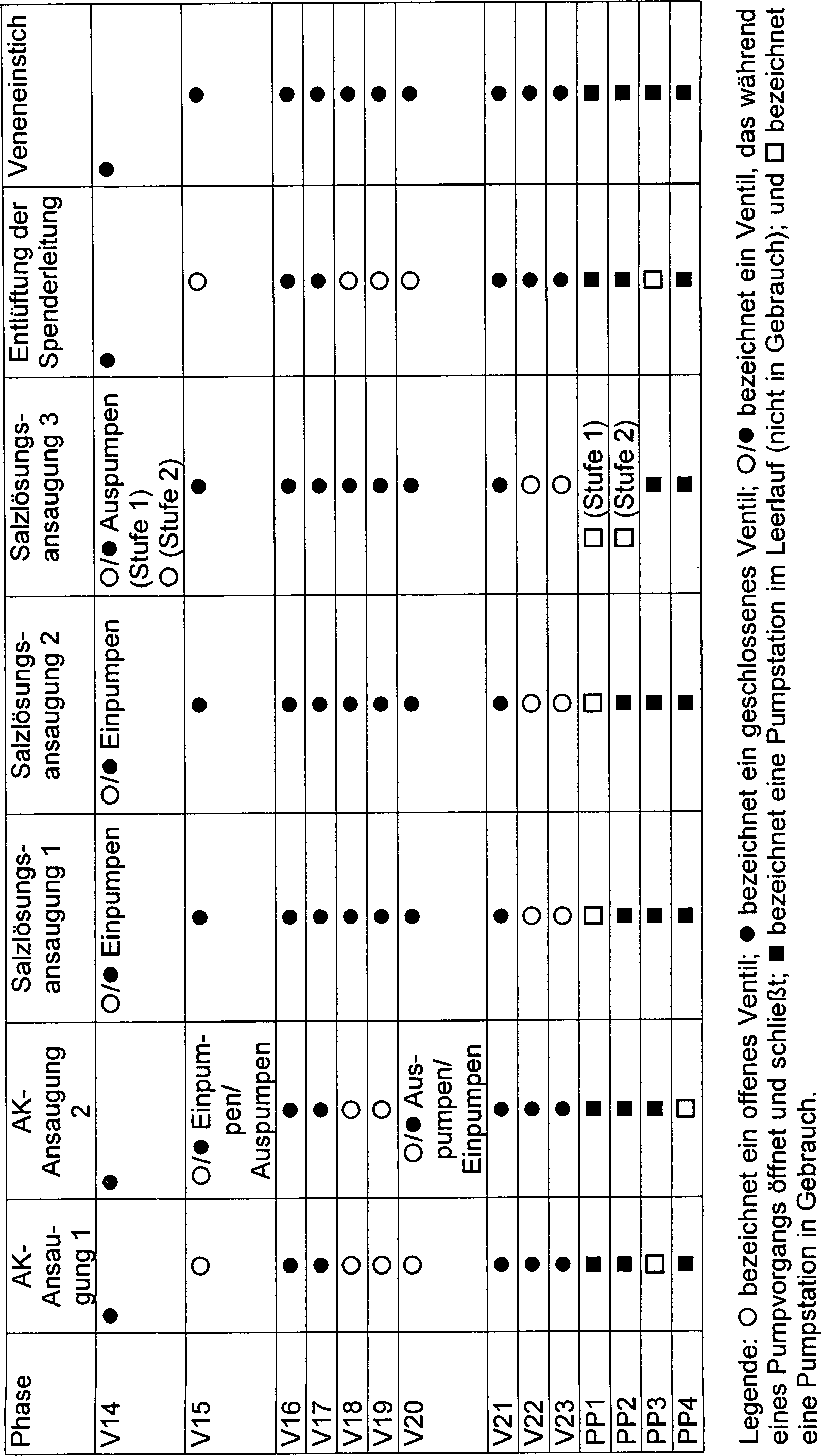
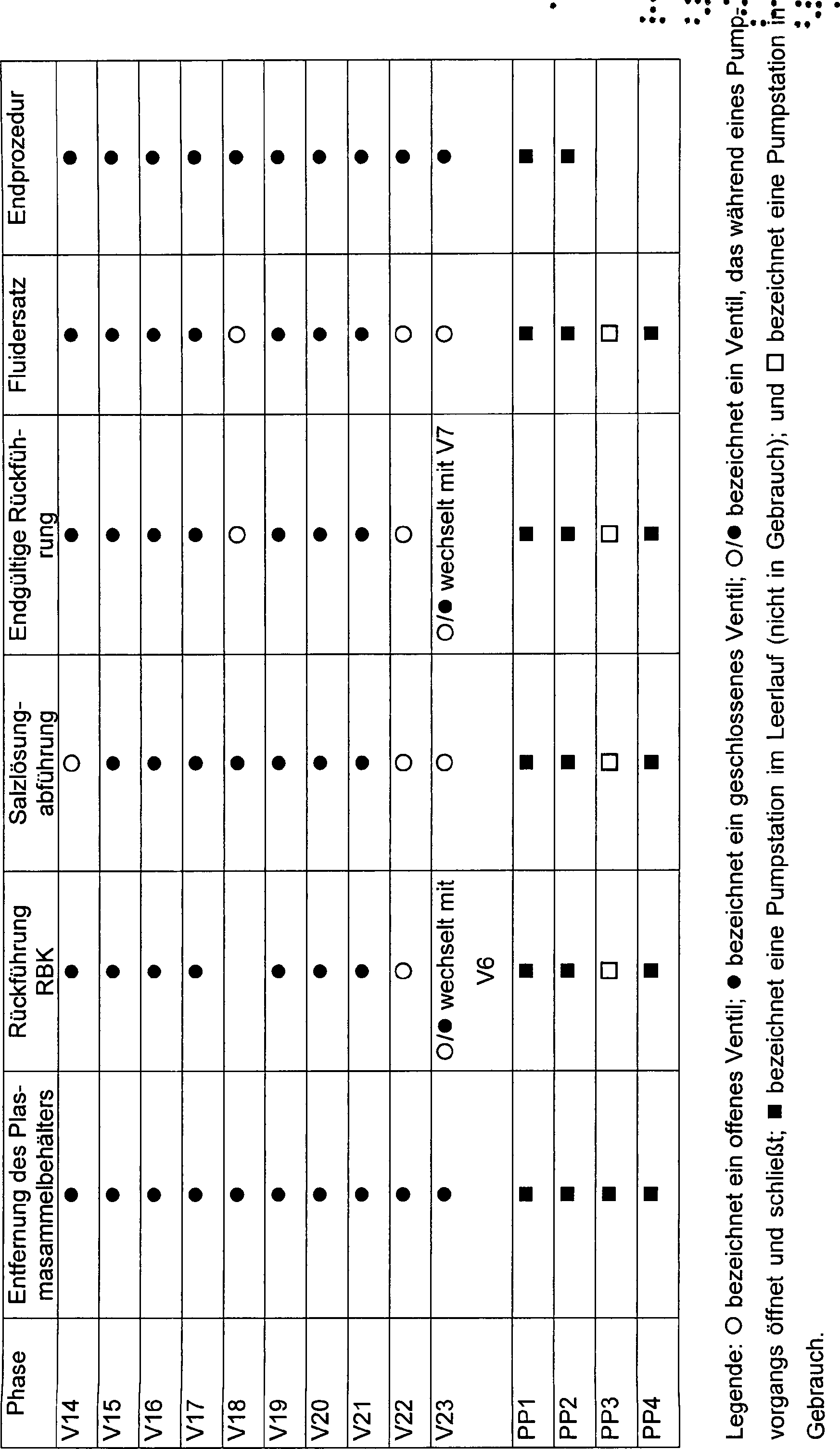
Der
Kreislauf 46 schließt
verschiedene Pumpstationen PP(N) ein, die miteinander durch ein
Muster von Fluidströmungspfaden
F(N) durch eine Anordnung von in Reihe geschalteten Ventilen V(N)
verbunden sind. Der Kreislauf ist mit dem Rest des Blutverarbeitungssets
durch Anschlüsse
P(N) verbunden.The circulation 46 includes various pump stations PP (N) connected together by a pattern of fluid flow paths F (N) through an array of valves V (N) connected in series. The circuit is connected to the remainder of the blood processing set through ports P (N).
Der
Kreislauf 46 schließt
ein programmierbares Netzwerk von Strömungspfaden ein, umfassend
elf universelle Anschlüsse
P1 bis P8 und P11 bis P13 und drei universelle Pumpstationen PP1,
PP2 und PP3. Durch den selektiven Betrieb der in Reihe geschalteten
Ventile V1 bis V14, V16 bis V18 und V21 bis V23, kann irgendein
universeller Anschluss P1 bis P8 und P11 bis P13 in Fließverbindung
mit irgendeiner universellen Pumpstation PP1, PP2 und PP3 angeordnet
werden. Durch den selektiven Betrieb der universellen Ventile kann
der Fluidfluss durch irgendeine universelle Pumpstation in einer
nach vorne gerichteten Richtung oder reversen Richtung zwischen
zwei Ventilen, oder in einer Innen-Außen Richtung durch ein einzelnes
Ventil geleitet werden.The circulation 46 includes a programmable network of flow paths comprising eleven universal ports P1 to P8 and P11 to P13 and three universal pumping stations PP1, PP2 and PP3. By the selective operation of the series valves V1 to V14, V16 to V18 and V21 to V23, any universal port P1 to P8 and P11 to P13 can be arranged in fluid communication with any universal pumping station PP1, PP2 and PP3. Through the selective operation of the universal valves, the fluid flow may be directed through any one universal pumping station in a forward direction or reverse direction between two valves, or in an inside-outside direction through a single valve.
In
der dargestellten Ausführungsform
schließt
der Kreislauf auch einen isolierten Strömungspfad umfassend zwei Anschlüsse P9 und
P10 und eine Pumpstation PP4 ein. Der Strömungspfad wird als "isoliert" bezeichnet, weil
er nicht in direkter Fließverbindung
mit irgendeinem anderen Strömungspfad
in dem Kreislauf 46 ohne äußeres Rohr, angeordnet werden
kann. Durch den selektiven Betrieb der in Reihe geschalteten Ventile
V15, V19 und V20 kann der Fluidfluss durch die Pumpstation in einer
nach vorne gerichteten Richtung oder reversen Richtung zwischen
zwei Ventilen, oder in einer Innen-Außen Richtung durch ein einzelnes
Ventil geleitet werden.In the illustrated embodiment, the circuit also includes an isolated flow path including two ports P9 and P10 and a pumping station PP4. The flow path is referred to as "isolated" because it is not in direct flow communication with any other flow path in the circuit 46 without outer tube, can be arranged. By selective operation of the series connected valves V15, V19 and V20, the fluid flow through the pumping station can be directed in a forward direction or reverse direction between two valves, or in an inside-outside direction through a single valve.
Der
Kreislauf 46 kann auf zugewiesene, zugeordnete Pumpfunktionen
in den verschiedenen Pumpstationen programmiert werden. Zum Beispiel
kann in einer bevorzugten Ausführungsform
die universelle Pumpstation PP3 einem allgemeinen Zweck als Spenderschnittstellenpumpe
dienen, unabhängig
von dem bestimmten Blutvorgang, der durchgeführt wird, um entweder Blut
von dem Spender zu entnehmen oder Blut an den Spender durch den
Anschluss P8 zurückzugeben.
In dieser Anordnung kann die Pumpstation PP4 als eine zugewiesene
Antikoagulanspumpe dienen, um Antikoagulans aus einer Quelle durch
den Anschluss P10 zu ziehen und das Antikoagulans in das Blut durch
den Anschluss P9 zu dosieren.The circulation 46 can be programmed to assigned assigned pumping functions in the various pumping stations. For example, in a preferred embodiment, the universal pumping station PP3 may serve a general purpose purpose as a donor interface pump, regardless of the particular blood process performed to either draw blood from the donor or return blood to the donor through port P8. In this arrangement, the pumping station PP4 may serve as an assigned anticoagulant pump to draw anticoagulant from a source through port P10 and dose the anticoagulant into the blood through port P9.
In
dieser Anordnung kann die universelle Pumpstation PP1, unabhängig von
dem bestimmten Blutverarbeitungsvorgang, der durchgeführt wird,
als eine zugeordnete prozessinterne Vollblutpumpe dienen, um Vollblut
in den Blutseparator zu leiten. Diese zugeordnete Funktion befreit
die Spenderschnittstellenpumpe PP3 von der zusätzlichen Funktion des Bereitstellens
von Vollblut an den Blutseparator. So kann die prozessinterne Vollblutpumpe
PP1 ein kontinuierliches Bereitstellen von Blut an den Blutseparator
aufrechterhalten, während die
Spenderschnittstellenpumpe PP3 gleichzeitig verwendet wird, um Blut
von dem Spender zu ziehen und an den Spender durch eine einzelne
Phlebotomie-Nadel zurückzugeben.
Die Vorgangszeit wird dadurch minimiert.In
this arrangement, the universal pumping station PP1, regardless of
the particular blood processing process being performed
serve as an attached in-process whole blood pump to whole blood
to lead into the blood separator. This assigned function frees
the dispenser interface pump PP3 from the additional function of providing
from whole blood to the blood separator. So can the in-process whole blood pump
PP1 provides a continuous supply of blood to the blood separator
maintained while the
Dispenser interface pump PP3 is used simultaneously to blood
from the donor to pull and to the donor by a single
Return phlebotomy needle.
The process time is thereby minimized.
In
dieser Anordnung kann die universelle Pumpstation PP2, unabhängig von
dem bestimmten Blutverarbeitungsvorgang, der durchgeführt wird,
als eine Plasmapumpe dienen, um Plasma von dem Blutseparator zu
leiten. Die Fähigkeit
getrennte Pumpfunktionen zuzuweisen, stellt einen kontinuierlichen
Blutfluss in und aus dem Separator, ebenso wie zu und von dem Spender
bereit.In
This arrangement allows the universal pumping station PP2, regardless of
the particular blood processing process being performed
serve as a plasma pump to deliver plasma from the blood separator
conduct. The ability
assign separate pumping functions, provides a continuous
Blood flow in and out of the separator, as well as to and from the donor
ready.
Der
Kreislauf 46 kann in Abhängigkeit von den Zielen des
bestimmten Blutverarbeitungsvorgangs programmiert werden, um das
gesamte oder einiges des Plasmas zur Lagerung oder für Fraktionierungszwecke zurückzuhalten,
oder um das Gesamte oder Einiges des Plasmas an den Spender zurückzugeben.
Der Kreislauf 46 kann weiterhin in Abhängigkeit von den Zielen des
bestimmten Blutverarbeitungsvorgangs programmiert werden, um alle
oder einige der roten Blutkörperchen
für die
Lagerung zurückzuhalten,
oder alle oder einige der roten Blutkörperchen an den Spender zurückzugeben.
Der Kreislauf 46 kann ebenfalls in Abhängigkeit von den Zielen des
bestimmten Blutverarbeitungsvorgangs programmiert werden, um den
gesamten oder einiges der Leukozytenfilm-Schicht für die Lagerung
zurückzuhalten,
oder den gesamten oder einiges der Leukozytenfilm-Schicht an den
Spender zurückzugeben.The circulation 46 may be programmed, depending on the goals of the particular blood processing operation, to retain all or some of the plasma for storage or fractionation purposes, or to return the whole or some of the plasma to the donor. The circulation 46 may also be programmed in response to the goals of the particular blood processing operation to retain all or some of the red blood cells for storage, or to return all or some of the red blood cells to the donor. The circulation 46 may also be programmed, depending on the objectives of the particular blood processing operation, to retain all or some of the buffy coat layer for storage, or to return all or some of the buffy coat layer to the donor.
In
einer bevorzugten Ausführungsform
ist der programmierbare Fluid Kreislauf 46 durch Verwendung einer
Fluiddruckgesteuerten Kassette 28 (siehe 6)
eingeschlossen. Die Kassette 28 stellt eine zentralisierte,
programmierbare, integrierte Plattform für all die Pump- und Ventilfunktionen
bereit, die für
einen gegebenen Blutverarbeitungsvorgang benötigt werden. In der dargestellten
Ausführungsform
umfasst der Fluiddruck einen positiven und negativen pneumatischen
Druck. Andere Typen von Fluiddrücken
können
verwendet werden.In a preferred embodiment, the programmable fluid is circulation 46 by using a fluid pressure controlled cartridge 28 (please refer 6 ) locked in. The cassette 28 provides a centralized, programmable, integrated platform for all the pump and valve functions needed for a given blood processing operation. In the illustrated embodiment, the fluid pressure includes positive and negative pneumatic pressures. Other types of fluid pressures may be used.
Wie
in 6 gezeigt, interagiert die Kassette 28 mit
einer druckgesteuerten Pump- und
Ventilstation 30, die in dem Deckel 40 des Gehäuses 36 (siehe 1)
befestigt ist. Die Kassette 28 ist, in der Verwendung, in
der Pump- und Ventilstation 30 angebracht. Die Pump- und
Ventilstation 30 überträgt positiven
und negativen pneumatischen Druck auf die Kassette 28,
um die Flüssigkeit
durch den Kreislauf zu leiten. Weitere Details werden später zur
Verfügung
gestellt.As in 6 shown, the cassette interacts 28 with a pressure-controlled pump and valve station 30 in the lid 40 of the housing 36 (please refer 1 ) is attached. The cassette 28 is, in use, in the pump and valve station 30 appropriate. The pump and valve station 30 transfers positive and negative pneumatic pressure to the cassette 28 to channel the fluid through the circuit. more details will be provided later.
Die
Kassette 28 kann verschiedene Formen annehmen. Wie dargestellt
(siehe 6), umfasst die Kassette 28 einen
Spritzgießkörper 188 mit
einer Vorderseite 190 und einer Rückseite 192. Für die Zwecke der
Beschreibung ist die Vorderseite 190 die Seite der Kassette 28 die,
wenn die Kassette 28 in der Pumpen- und Ventilstation 30 angebracht
ist, von der Bedienperson weg gerichtet ist. Bewegliche Membranen 194 und 196 liegen
jeweils auf beiden, der Vorderseite 190 und den Rückseiten 192 der
Kassette 28, auf.The cassette 28 can take different forms. As shown (see 6 ), includes the cassette 28 an injection-molded body 188 with a front side 190 and a back 192 , For the purpose of description is the front 190 the side of the cassette 28 the when the cassette 28 in the pump and valve station 30 attached is directed away from the operator. Mobile membranes 194 and 196 lie respectively on both, the front 190 and the backs 192 the cassette 28 , on.
Der
Kassettenkörper 188 ist
vorzugsweise aus einem steifen Kunststoffmaterial medizinischer
Güteklasse
hergestellt. Die Membranen 194 und 196 sind vorzugsweise
aus beweglichen Blättern
aus Kunststoff medizinischer Güteklasse
hergestellt. Die Membranen 194 und 196 sind an
ihren Umfängen
zu den Umfangskanten der Vorder- und Rückseiten des Kassettenkörpers 188 abgedichtet.
Innere Bereiche der Membranen 194 und 196 können auch
zu den inneren Bereichen des Kassettenkörpers 187 abgedichtet
sein.The cassette body 188 is preferably made of a rigid plastic medical grade material. The membranes 194 and 196 are preferably made of movable sheets of medical grade plastic. The membranes 194 and 196 are at their peripheries to the peripheral edges of the front and rear sides of the cartridge body 188 sealed. Inner regions of the membranes 194 and 196 can also to the inner areas of the cassette body 187 be sealed.
Der
Kassettenkörper 188 weist
eine Anordnung von inneren Hohlräumen
auf, die an beiden, den Vorder- und Rückseiten 190 und 192 (siehe 7 und 9),
ausgebildet sind. Die inneren Hohlräume definieren die Ventilstationen
und Strömungspfade,
die schematisch in 5 dargestellt sind. Ein zusätzlicher
innerer Hohlraum ist an der Rückseite
der Kassette 28 zur Verfügung gestellt, um eine Station
zu bilden, die ein Filtermaterial 200 enthält. In der
dargestellten Ausführungsform
umfasst das Filtermaterial 200 eine darüber geformte Netzfilterkonstruktion.
Das Filtermaterial 200 ist dazu vorgesehen, während des
Gebrauchs Blutgerinnsel und Zellansammlungen zu entfernen, die sich
während
der Blutverarbeitung bilden können.The cassette body 188 has an array of internal cavities located on both the front and back sides 190 and 192 (please refer 7 and 9 ), are formed. The internal cavities define the valve stations and flow paths, which are schematically shown in FIG 5 are shown. An additional internal cavity is at the back of the cassette 28 provided to form a station containing a filter material 200 contains. In the illustrated embodiment, the filter material comprises 200 a net filter construction formed over it. The filter material 200 is intended to remove blood clots and cell accumulations during use that may form during blood processing.
Die
Pumpstationen PP1 bis PP4 sind als Schächte geformt, die auf der Vorderseite 190 des
Kassettenkörpers 188 offen
sind. Hochstehende Kanten umgeben die offenen Schächte der
Pumpstationen am Umfang. Die Pumpenschächte sind auf der Rückseite 192 des
Kassettenkörpers 188 geschlossen,
bis auf ein beabstandetes Paar von Durchgangslöchern oder Anschlüssen 202 und 204 für jede Pumpstation.
Die Anschlüsse 202 und 204 erstrecken
sich durch die Rückseite 192 des
Kassettenkörpers 188 hindurch.
Wie offenbar wird, kann jeder Anschluss 202 oder 204 seiner
zu gehörigen
Pumpstation als Einlass oder Auslass oder sowohl als Einlass als
auch als Auslass dienen.The pumping stations PP1 to PP4 are shaped as manholes, those on the front 190 of the cartridge body 188 are open. Rising edges surround the open shafts of the pumping stations on the circumference. The pump shafts are on the back 192 of the cartridge body 188 closed, except for a spaced pair of through holes or terminals 202 and 204 for every pump station. The connections 202 and 204 extend through the back 192 of the cartridge body 188 therethrough. As is apparent, every connection can 202 or 204 its associated pumping station as an inlet or outlet or serve both as an inlet and as an outlet.
Die
Ventile V1 bis V23 in Reihe sind ebenso als Schächte ausgebildet, die auf der
Vorderseite 190 der Kassette offen sind. 8 zeigt
ein typisches Ventil V(N). Hochstehende Kanten umgeben die offenen Schächte der
Ventile auf der Vorderseite 190 des Kassettenkörpers 188 am
Umfang. Die Ventile sind auf der Rückseite 192 der Kassette 28 geschlossen,
außer
dass jedes Ventil ein Paar Durchgangslöcher oder Anschlüsse 206 und 208 einschließt. Ein
Anschluss 206 steht in Verbindung mit einem ausgewählten Flüssigkeitspfad
auf der Rückseite 192 des
Kassettenkörpers 188.
Der andere Anschluss 208 kommuniziert mit einem ausgewählten Flüssigkeitspfad
auf der Rückseite 192 des
Kassettenkörpers 188.The valves V1 to V23 in series are also formed as wells, which on the front 190 the cassette are open. 8th shows a typical valve V (N). Rising edges surround the open shafts of the valves on the front 190 of the cartridge body 188 at the extent. The valves are on the back 192 the cassette 28 closed, except that each valve has a pair of through holes or connections 206 and 208 includes. A connection 206 Connects to a selected fluid path on the back 192 of the cartridge body 188 , The other connection 208 communicates with a selected fluid path on the back 192 of the cartridge body 188 ,
In
jedem Ventil erstreckt sich ein Ventilsitz 210 um einen
der Anschlüsse 208.
Der Ventilsitz 210 ist vertieft unter der Oberfläche des
vertieften Ventilschachts, so dass der Anschluss 208 im
Wesentlichen bündig ist
mit der umgebenden Oberfläche
des vertieften Ventilschachts und der Ventilsitz 206 sich
unter die Oberfläche
des Ventilschachts erstreckt.In each valve, a valve seat extends 210 around one of the connections 208 , The valve seat 210 is recessed under the surface of the recessed valve well, leaving the port 208 is substantially flush with the surrounding surface of the recessed valve well and the valve seat 206 extends below the surface of the valve well.
Die
flexible Membran 194, die auf der Vorderseite 190 der
Kassette 28 aufliegt, ruht auf den hochstehenden Umfangskanten,
die die Pumpstationen und -ventile umgeben. Mit dem Aufbringen einer
positiven Kraft, einheitlich gegen diese Seite des Kassettenkörpers 188,
sitzt die bewegliche Membran 194 gegen die hochstehenden
Kanten. Die positive Kraft bildet Umfangsdichtungen um die Pumpstationen
und -ventile. Dieses wiederum isoliert die Pumpen und Ventile voneinander
und vom Rest des Systems. Die Pumpen- und Ventilstation 30 bringt
zu diesem Zweck eine positive Kraft auf die Vorderseite 190 des
Kassettenkörpers 188 auf.The flexible membrane 194 on the front 190 the cassette 28 rests resting on the upstanding peripheral edges surrounding the pumping stations and valves. With the application of a positive force, uniform against this side of the cartridge body 188 , the movable membrane sits 194 against the upstanding edges. The positive force forms circumferential seals around the pumping stations and valves. This in turn isolates the pumps and valves from each other and from the rest of the system. The pump and valve station 30 For this purpose, bring a positive force to the front 190 of the cartridge body 188 on.
Ein
weiteres örtlich
begrenztes Aufbringen von positiven und negativen Fluiddrücken auf
die Bereiche der Membran 194, die auf diesen am Umfang
abgedichteten Flächen
aufliegt, dient zur Beugung der Membranbereiche in diesen am Umfang
abgedichteten Flächen.
Dieses örtlich
begrenzte Aufbringen von positiven und negativen Fluiddrücken auf
diese Membranbereiche, die auf den Pumpstationen aufliegen, dienen
zum Ausstoßen
von Flüssigkeit
aus den Pumpstationen (mit Anwendung von positivem Druck) und zum
Ansaugen von Flüssigkeit
in die Pumpstationen (mit Aufbringen von negativem Druck).Another localized application of positive and negative fluid pressures to the areas of the membrane 194 , which rests on these circumferentially sealed surfaces, serves to diffract the membrane areas in these circumferentially sealed areas. This localized application of positive and negative fluid pressures to these membrane areas, which rest on the pump stations, serves to expel fluid from the pump stations (using positive pressure) and to aspirate fluid into the pump stations (with application of negative pressure).
In
der dargestellten Ausführungsform
schließt
der Boden jeder Pumpstation PP1 bis PP4 einen vertieften Überlauf 316 (siehe 7)
ein. Der Überlauf 316 erstreckt
sich zwischen den Anschlüssen 202 und 204 und
schließt
auch ein Anschlagbein ein, das sich in einem Winkel zu dem oberen
Anschluss 202 erstreckt. Der Überlauf 316 stellt
eine bessere Flüssigkeitsströmungsstetigkeit
zwischen den Anschlüssen 202 und 204 zur Verfügung, insbesondere
wenn der Membranbereich durch ein positiven Druck gegen den Boden
der Pumpstation getrieben wird. Der Überlauf 316 verhindert
auch, dass der Membranbereich innerhalb der Pumpstation Luft einfängt. Luft
innerhalb der Pumpstation wird in den Überlauf 316 getrieben,
wo sie einfach durch den oberen Anschluss 202 aus der Pumpstation
entlüften
kann, auch wenn der Membranbereich den Boden in der Pumpstation
erreicht.In the illustrated embodiment, the bottom of each pump station PP1 to PP4 includes a recessed overflow 316 (please refer 7 ) one. The overflow 316 extends between the terminals 202 and 204 and also includes an impact leg that extends at an angle to the upper port 202 extends. Of the overflow 316 provides better fluid flow continuity between the ports 202 and 204 available, especially when the membrane area is driven by a positive pressure against the bottom of the pumping station. The overflow 316 also prevents the membrane area inside the pumping station from capturing air. Air inside the pumping station gets into the overflow 316 driven where they simply pass through the top port 202 from the pumping station, even if the membrane area reaches the bottom in the pumping station.
Ebenso
werden örtliche
begrenzte Aufbringungen von positivem und negativem Fluiddruck auf
die Membranbereiche, die auf den Ventilen aufliegen, dienen, um
(mit Aufbringen eines positiven Drucks) diese Membranbereiche zu
setzen und (mit Aufbringen eines negativen Drucks) von den Ventilsitzen
abzuheben, wodurch der zugehörige
Ventilanschluss geschlossen und geöffnet wird. Die bewegliche
Membran reagiert auf einen aufgebrachten negativen Druck zum Beugen
aus dem Ventilsitz 210, um den entsprechenden Anschluss zu öffnen. Die
bewegliche Membran reagiert auf einen aufgebrachten positiven Druck
zum Beugen in den Ventilsitz 210, um den entsprechenden
Anschluss zu schließen.
Dichtung wird erreicht durch Treiben der beweglichen Membran, um
in den vertieften Ventilsitz 210 zu beugen, um um den Anschluss 208 zu
dichten, welcher bündig
mit der Wand des Ventilschachts ist. Die bewegliche Membran bildet
innerhalb des vertieften Ventilsitzes 210 eine Umfangsdichtung
um den Ventilanschluss 208.Likewise, localized application of positive and negative fluid pressure to the membrane areas which rest on the valves will serve to set (with application of positive pressure) those membrane areas and lift them off (with negative pressure applied) from the valve seats, thereby increasing the associated pressure Valve connection is closed and opened. The movable diaphragm responds to an applied negative pressure for flexing out of the valve seat 210 to open the corresponding port. The movable diaphragm responds to an applied positive pressure for flexing into the valve seat 210 to close the corresponding port. Seal is achieved by urging the movable diaphragm to enter the recessed valve seat 210 to bow to the connection 208 to seal, which is flush with the wall of the valve shaft. The movable diaphragm forms within the recessed valve seat 210 a circumferential seal around the valve port 208 ,
Im
Betrieb bringt die Pumpen- und Ventilstation 30 örtlich begrenzte
positive und negative Fluiddrücke auf
diese Bereiche der vorderen Membran 104 zum Öffnen und
Schließen
der Ventilanschlüsse
auf.In operation brings the pump and valve station 30 localized positive and negative fluid pressures on these areas of the anterior membrane 104 for opening and closing the valve connections.
Die
Flüssigkeitspfade
F1 bis F38 sind als verlängerte
Kanäle
ausgebildet, die auf der Rückseite 192 des
Kassettenkörpers 188 offen
sind, bis auf die Flüssigkeitspfade
F15, F23 und F24, die als verlängerte
Kanäle
ausgebildet sind, die auf der Vorderseite 190 des Kassettenkörpers 188 offen
sind. Die Flüssigkeitspfade sind
in 9 schattiert um deren Ansicht zu erleichtern.
Hochstehende Kanten umgeben die offenen Kanäle am Umfang auf den Vorder-
und Rückseiten 190 und 192 des
Kassettenkörpers 188.The fluid paths F1 to F38 are designed as extended channels, those on the back 192 of the cartridge body 188 are open, except for the liquid paths F15, F23 and F24, which are formed as elongated channels on the front 190 of the cartridge body 188 are open. The fluid paths are in 9 shaded to make their view easier. Raised edges surround the open channels on the perimeter on the front and back sides 190 and 192 of the cartridge body 188 ,
Die
Flüssigkeitspfade
F1 bis F38 sind auf der Vorderseite 190 des Kassettenkörpers 188 geschlossen, außer wo die
Kanäle
die Ventilstationsanschlüsse
oder Pumpstationsanschlüsse
kreuzen. Ebenso sind die Flüssigkeitspfade
F31 bis F38 auf der Rückseite 192 des
Kassettenkörpers 188 geschlossen,
außer
wo die Kanäle
die Anschlüsse
in Reihe, die mit bestimmten Kanälen
auf der Rückseite 192 der
Kassette 28 kommunizieren, kreuzen.Fluid paths F1 through F38 are on the front 190 of the cartridge body 188 closed except where the channels cross the valve station ports or pump station ports. Likewise, the fluid paths F31 to F38 are on the back 192 of the cartridge body 188 closed, except where the channels are connected in series with certain channels on the back 192 the cassette 28 communicate, cross.
Die
beweglichen Membranen 194 und 196, die auf den
Vorder- und Rückseiten 190 und 192 des
Kassettenkörpers 188 aufliegen,
ruhen gegen die hochstehenden Umfangskanten, die die Flüssigkeitspfade
F1 bis F38 umgeben. Mit dem Aufbringen einer positiven Kraft, einheitlich
gegen die Vorder- und Rückseiten 190 und 192 des
Kassettenkörpers 188,
setzen die beweglichen Membranen 194 und 196 gegen
die hochstehenden Kanten. Dieses bildet Umfangsdichtungen entlang
der Flüssigkeitspfade
F1 bis F38. Im Betrieb bringt die Pumpen- und Ventilstation 30 eine
positive Kraft auf die Membranen 194 und 196 zu
diesem Zweck auf.The mobile membranes 194 and 196 on the front and back 190 and 192 of the cartridge body 188 rest against the upstanding peripheral edges surrounding the fluid paths F1 to F38. With the application of a positive force, uniform against the front and back sides 190 and 192 of the cartridge body 188 Put the moving membranes 194 and 196 against the upstanding edges. This forms circumferential seals along the liquid paths F1 to F38. In operation brings the pump and valve station 30 a positive force on the membranes 194 and 196 for this purpose.
Die
vorgeformten Anschlüsse
P1 bis P13 erstrecken sich entlang zweier Seitenkanten des Kassettenkörpers 188.
Die Kassette 28 ist vertikal angebracht für die Verwendung
in der Pumpen- und Ventilstation 30 (siehe 2).
In dieser Ausrichtung sind die Anschlüsse P8 bis P13 nach unten gerichtet,
und die Anschlüsse P1
bis P7 sind vertikal gestapelt, einer über dem anderen, und nach innen
gerichtet.The preformed terminals P1 to P13 extend along two side edges of the cartridge body 188 , The cassette 28 is vertically mounted for use in the pump and valve station 30 (please refer 2 ). In this orientation, the terminals P8 to P13 are directed downwards and the terminals P1 to P7 are stacked vertically, one above the other, and inward.
Wie 2 darstellt,
sind die Anschlüsse
P8 bis P13, dadurch dass sie nach unten gerichtet sind, an Behälterstützwannen 212 ausgerichtet,
die im Boden 38 ausgebildet sind, wie später beschrieben
wird. Die Anschlüsse
P1 bis P7, die nach innen gerichtet sind, sind ausgerichtet an der
Zentrifugenstation 20 und an einer Behälterwiegestation 214,
wie ebenfalls später
ausführlicher
beschrieben wird. Die Ausrichtung der Anschlüsse P5 bis P7 (welche der Verarbeitungskammer 18 dienen)
unterhalb der Anschlüsse
P1 bis P4 verhindern, dass Luft in die Verarbeitungskammer 18 eintritt.As 2 3, the ports P8 to P13 are attached to container support pans by being directed downwardly 212 aligned in the ground 38 are formed, as will be described later. The ports P1 to P7 facing inward are aligned with the centrifuge station 20 and at a container weighing station 214 , as also described in more detail later. The orientation of the ports P5 to P7 (which of the processing chamber 18 serve) below the ports P1 to P4 prevent air from entering the processing chamber 18 entry.
Diese
geordnete Ausrichtung der Anschlüsse
stellt eine zentralisierte, kompakte Einheit zur Verfügung, die
auf die betriebsbereiten Bereiche des Kastens 36 ausgerichtet
sind.This orderly alignment of the connections provides a centralized, compact unit that points to the operational areas of the box 36 are aligned.
B. Das UniversalsetB. The universal set
10 stellt schematisch ein Universalset 264 dar,
welches durch gezielte Programmierung des Blutverarbeitungsschaltkreises 46,
ausgeführt
durch die Kassette 28, in der Lage ist, mehrere verschiedene
Blutverarbeitungsprozeduren auszuführen. 10 schematically represents a universal set 264 which is by targeted programming of the blood processing circuit 46 , performed by the cassette 28 capable of performing several different blood processing procedures.
Das
Universalset 264 schließt einen Spenderschlauch 266,
welcher (durch y-Verbinder 272 und 273) an
dem Schlauch 300 befestigt ist, der eine angeschlossene
Aderlassnadel 268 aufweist, ein. Der Spenderschlauch 266 ist
an den Anschluss P8 der Kassette 28 angekoppelt.The universal set 264 closes a donor tube 266 , which (by y-connector 272 and 273 ) on the hose 300 attached, the one connected Aderlassnadel 268 has, a. The donor tube 266 is to port P8 of the cassette 28 coupled.
Ein
Behälter 275 zum
Sammeln einer Reihenblutprobe, die durch den Schlauch 300 gezogen
wird, ist auch durch einen y-Verbinder 273 befestigt.A container 275 to collect a series blood sample through the tube 300 is also pulled through a y-connector 273 attached.
Ein
Antikoagulansschlauch 270 ist durch den y-Verbinder 272 an
die Aderlassnadel 268 gekoppelt. Der Antikoagulansschlauch 270 ist
an den Kassettenanschluss P9 gekoppelt. Ein Behälter 276, der Antikoagulans
enthält,
ist durch einen Schlauch 274 an den Kassettenanschluss
P10 gekoppelt. Der Antikoagulansschlauch 270 trägt eine
externe, von Hand betriebene Reihenklemme 282 herkömmlicher
Konstruktion.An anticoagulant tube 270 is through the y-connector 272 to the bloodletting needle 268 coupled. The anticoagulant tube 270 is coupled to the cassette port P9. A container 276 that contains anticoagulant is through a tube 274 coupled to the cassette port P10. The anticoagulant tube 270 carries an external, manually operated terminal block 282 conventional construction.
Ein
Behälter 280,
der eine Rote-Blutkörperchen-Zusatzlösung enthält, ist
durch einen Schlauch 278 an den Kassettenanschluss P3 gekoppelt.
Der Schlauch 278 trägt
auch eine externe, manuell betriebene Klemme 282 in Reihe.A container 280 which contains a red blood cell supplement solution is through a tube 278 coupled to the cassette port P3. The hose 278 Also carries an external, manually operated terminal 282 in row.
Ein
Behälter 288,
der eine Salzlösung
enthält,
ist durch einen Schlauch 284 an den Kassettenanschluss
P12 gekoppelt.A container 288 which contains a saline solution is through a tube 284 coupled to the cassette port P12.
10 stellt die Fluid enthaltenden Behälter 276, 280 und 288 als
integral befestigt während
der Herstellung des Sets 264 dar. Alternativ können alle
oder einige der Behälter 276, 280 und 288 getrennt
von dem Set 264 geliefert werden. Die Behälter 276, 280 und 288 können durch
herkömmliche
Stiftverbinder gekoppelt werden, oder das Set 264 kann
konfiguriert sein, das Zubehör
des getrennten Behälters
oder der Behälter
zu der Zeit der Benutzung durch eine geeignete sterile Verbindung
aufzunehmen, um dadurch eine sterile, geschlossene Blutverarbeitungsumgebung
aufrecht zu erhalten. Alternativ können die Schläuche 274, 278 und 284 einen
Sterilisierfilter in Reihe und einen herkömmlichen Stiftverbinder zum
Einstecken in den Behälteranschluss
zur Zeit der Benutzung tragen, um dadurch eine sterile, geschlossene
Blutverarbeitungsumgebung aufrecht zu erhalten. 10 represents the fluid-containing container 276 . 280 and 288 as integrally fastened during the manufacture of the set 264 Alternatively, all or some of the containers 276 . 280 and 288 separated from the set 264 to be delivered. The containers 276 . 280 and 288 can be coupled by conventional pin connectors, or the set 264 may be configured to receive the accessories of the separate container or containers at the time of use by a suitable sterile connection to thereby maintain a sterile, closed blood processing environment. Alternatively, the hoses 274 . 278 and 284 a sterilizing filter in series and a conventional pin connector for insertion into the container port at the time of use, thereby maintaining a sterile, closed blood processing environment.
Das
Set 264 schließt
weiterhin Schläuche 290, 292, 294 ein,
welche sich bis zu einem Nabelschlauch 296 erstrecken.
Wenn er an die Verarbeitungsstation angeschlossen ist, verbindet
der Nabelschlauch die rotierende Verarbeitungskammer 18 mit
der Kassette 28, ohne den Bedarf für Rotationsdichtungen. Weitere
Einzelheiten dieser Konstruktion werden später zur Verfügung gestellt.The set 264 continues to close hoses 290 . 292 . 294 one which extends to a navel tube 296 extend. When connected to the processing station, the umbilical hose connects the rotating processing chamber 18 with the cassette 28 without the need for rotary seals. Further details of this construction will be provided later.
Die
Schläuche 290, 292 und 294 sind
jeweils an die Kassettenanschlüsse
P5, P6 und P7 gekoppelt. Der Schlauch 290 fördert Vollblut
in die Verarbeitungskammer 18. Der Schlauch 292 fördert Plasma
von der Verarbeitungskammer 18. Der Schlauch 294 fördert rote
Blutkörperchen
von der Verarbeitungskammer 18.The tubes 290 . 292 and 294 are each coupled to the cartridge ports P5, P6 and P7. The hose 290 promotes whole blood into the processing chamber 18 , The hose 292 promotes plasma from the processing chamber 18 , The hose 294 promotes red blood cells from the processing chamber 18 ,
Ein
Plasmasammelbehälter 304 ist
durch einen Schlauch 302 an den Kassettenanschluss P3 gekoppelt.
Der Sammelbehälter 304 ist
im Betrieb vorgesehen, als Reservoir für Plasma während der Verarbeitung zu dienen.A plasma collection container 304 is through a hose 302 coupled to the cassette port P3. The collection container 304 is intended in operation to serve as a reservoir for plasma during processing.
Ein
Rote-Blutkörperchen-Sammelbehälter 308 ist
durch einen Schlauch 306 an den Kassettenanschluss P2 gekoppelt.
Der Sammelbehälter 308 ist
im Betrieb vorgesehen, eine erste Einheit von roten Blutkörperchen
zum Speichern zu erhalten.A red blood cell collection container 308 is through a hose 306 coupled to the cassette port P2. The collection container 308 In operation, it is intended to obtain a first unit of red blood cells for storage.
Ein
Vollblut Reservoir 312 ist durch einen Schlauch 310 an
den Kassettenanschluss P1 gekoppelt. Der Sammelbehälter 312 ist
im Betrieb dazu vorgesehen, als Reservoir für Vollblut während der
Verarbeitung zu dienen. Er kann auch dazu dienen, eine zweite Einheit
von roten Blutkörperchen
zum Speichern zu erhalten.A thoroughbred reservoir 312 is through a hose 310 coupled to the cassette port P1. The collection container 312 in operation is intended to serve as a reservoir for whole blood during processing. It can also serve to obtain a second unit of red blood cells for storage.
Wie
in 10 dargestellt, ist kein Schlauchmaterial an den
Universalkassettenanschluss P13 und an den Leukozytenfilm-Anschluss
P4 gekoppelt.As in 10 No tubing is coupled to the universal cassette port P13 and leukocyte port P4.
C. Die Pumpen- und VentilstationC. The pump and valve station
Die
Pumpen- und Ventilstation 30 schließt einen Kassettenhalter 216 ein.
Die Tür 32 ist
schwenkbar, um sich in Bezug auf den Kassettenhalter 216 zwischen
der geöffneten
Position, die den Kassettenhalter 216 (in 6 dargestellt)
aufdeckt, und der geschlossenen Position, die den Kassettenhalter 216 (in 3 dargestellt)
abdeckt, zu bewegen. Die Tür 32 schließt auch
einen Schnappverschluss 218 ü ber der Mitte mit einem Schnappverschlussgriff 220 ein.
Wenn die Tür 32 geschlossen
wird, schwingt der Schnappverschluss 218 in einen Eingriff
mit der Schnappverschlussnadel 222 ein.The pump and valve station 30 closes a cassette holder 216 one. The door 32 is pivotable to itself in relation to the cassette holder 216 between the open position holding the cassette holder 216 (in 6 shown), and the closed position, the cassette holder 216 (in 3 shown), to move. The door 32 also includes a snap closure 218 Over the middle with a snap lock handle 220 one. If the door 32 closed, the snap closure swings 218 in an engagement with the snap-lock needle 222 one.
Wie 11 darstellt, trägt die innere Vorderseite der
Tür 32 eine
elastomere Dichtung 224. Die Dichtung 224 berührt die
Rückseite 192 der
Kassette 28, wenn die Tür 32 geschlossen
ist. Eine aufblasbare Blase 314 liegt unter der Dichtung 224.As 11 represents, carries the inner front of the door 32 an elastomeric seal 224 , The seal 224 touches the back 192 the cassette 28 when the door 32 closed is. An inflatable bubble 314 lies under the seal 224 ,
Wenn
die Tür 32 geöffnet ist
(siehe 2), kann die Bedienperson die
Kassette 28 in den Kassettenhalter 216 setzen.
Das Schließen
der Tür 32 und
das Sichern des Schnappverschlusses 218 bringt die Dichtung
in gegenüberliegenden
Kontakt mit der Membran 196 auf der Rückseite 192 der Kassette 28.
Indem die Blase 314 aufgeblasen wird, drückt die
Dichtung 224 in intimem Dichtungseingriff gegen die Membran 196.
Die Kassette 28 ist dadurch in einer engen, dichtenden
Passung innerhalb des Kassettenhalters 216 gesichert.If the door 32 is open (see 2 ), the operator can the cassette 28 in the cassette holder 216 put. The closing of the door 32 and securing the snap closure 218 puts the seal in opposite contact with the membrane 196 on the back side 192 the cassette 28 , By the bubble 314 is inflated, pushes the seal 224 in intimate sealing engagement against the membrane 196 , The cassette 28 is thereby in a tight, sealing fit within the cassette holder 216 secured.
Das
Aufblasen der Blase 314 drückt auch den Schnappverschluss 218 über der
Mitte vollständig
gegen die Schnappverschlussnadel 222 mit einer Kraft, die
durch normale manuelle Kraft nicht überwunden werden kann, gegen
den Schnappverschlussgriff 220. Die Tür 32 ist sicher abgeschlossen
und kann nicht geöffnet werden,
wenn die Blase 314 aufgeblasen ist. In dieser Konstruktion
gibt es keinen Bedarf für
eine Hilfssperrvorrichtung oder einen Sensor, um gegen das Öffnen der
Tür 32 während der
Blutverarbeitung abzusichern.The inflation of the bladder 314 also pushes the snap closure 218 over the middle completely against the snap-lock needle 222 with a force that can not be overcome by normal manual force, against the snap lock handle 220 , The door 32 is safely completed and can not be opened when the bubble 314 is inflated. In this construction there is no need for an auxiliary locking device or a sensor to prevent the door from being opened 32 during blood processing.
Die
Pumpen- und Ventilstation 30 schließt auch eine Verteileranordnung 226 ein,
die in dem Kassettenhalter 216 angeordnet ist. Die Verteileranordnung 226 umfasst
einen geformten oder bearbeiteten Kunststoff- oder Metallkörper. Die
Vorderseite 194 der Membran wird in intimem Eingriff gegen
die Verteileranordnung 226 gehalten, wenn die Tür 32 geschlossen
und die Blase 314 aufgeblasen ist.The pump and valve station 30 also includes a distributor assembly 226 one in the cassette holder 216 is arranged. The distributor arrangement 226 comprises a molded or machined plastic or metal body. The front 194 the diaphragm is intimately engaged against the manifold assembly 226 kept when the door 32 closed and the bubble 314 is inflated.
Die
Verteileranordnung 226 ist an eine pneumatische Druckquelle 234 gekoppelt,
welche positiven und negativen Luftdruck liefert. Die pneumatische
Druckquelle 234 ist innerhalb des Deckels 40 hinter
der Verteileranordnung 22.6 ausgeführt.The distributor arrangement 226 is to a pneumatic pressure source 234 coupled, which provides positive and negative air pressure. The pneumatic pressure source 234 is inside the lid 40 behind the distributor arrangement 22.6 executed.
In
der dargestellten Ausführungsform
umfasst die Druckquelle 234 zwei Kompressoren K1 und K2.
Es könnten
jedoch auch einer oder mehrere Doppelkopfkompressoren verwendet
werden. Wie 12 darstellt, liefert ein Kompressor
K1 negativen Druck durch den Verteiler 226 an die Kassette 28.
Der andere Kompressor K2 liefert positiven Druck durch den Verteiler 226 an
die Kassette 28.In the illustrated embodiment, the pressure source comprises 234 two compressors K1 and K2. However, one or more dual-head compressors could be used. As 12 represents, a compressor K1 provides negative pressure through the manifold 226 to the cassette 28 , The other compressor K2 delivers positive pressure through the manifold 226 to the cassette 28 ,
Wie 12 darstellt, umfasst der Verteiler 226 vier
Pumpenaktuatoren PA1 bis PA4 und dreiundzwanzig Ventilaktuatoren
VA1 bis V23. Die Pumpakutatoren PA1 bis PA4 und die Ventilaktuatoren
VA1 bis VA23 sind gegenseitig aneinander ausgerichtet, um ein Spiegelbild
der Pumpstationen PP1 bis PP4 und der Ventilstationen V1 bis V23
auf der Vorderseite 190 der Kassette 28 zu bilden.As 12 represents the distributor includes 226 four pump actuators PA1 to PA4 and twenty-three valve actuators VA1 to V23. The pump actuators PA1 to PA4 and the valve actuators VA1 to VA23 are mutually aligned to form a mirror image of the pumping stations PP1 to PP4 and the valve stations V1 to V23 on the front side 190 the cassette 28 to build.
Wie 12 auch zeigt, schließt jeder Aktuator PA1 bis PA4
und VA1 bis VA23 einen Anschluss 228 ein. Die Anschlüsse 228 fördern positive
oder negative pneumatische Drücke
von der Quelle in einer Folge, die durch den Regler 16 bestimmt
wird. Diese positiven und negativen Druckpulse beugen die vordere
Membran 194, um auf die Pumpenkammern PP1 bis PP4 und die
Ventilstationen V1 bis V23 in der Kassette 28 einzuwirken.
Dieses wiederum bewegt Blut und Verarbeitungsflüssigkeit durch die Kassette 28.As 12 Also, each actuator closes PA1 to PA4 and VA1 to VA23 one terminal 228 one. The connections 228 Promote positive or negative pneumatic pressures from the source in a sequence created by the regulator 16 is determined. These positive and negative pressure pulses bend the anterior membrane 194 to the pump chambers PP1 to PP4 and the valve stations V1 to V23 in the cassette 28 act. This in turn moves blood and processing fluid through the cartridge 28 ,
Der
Kassettenhalter 216 schließt vorzugsweise eine integrale
elastomere Membran 232 (siehe 6) ein,
die sich über
die Verteileranordnung 226 erstreckt. Die Membran 232 dient
als die Schnittstelle zwischen dem Kolbenelement 226 und
der Membran 194 der Kassette 28, wenn sie in den
Halter 216 eingepasst ist. Die Membran 232 kann
ein oder mehrere kleine Durchgangslöcher (nicht dargestellt) in
den Regionen einschließen,
die auf den Pumpen- und Ventilaktuatoren PA1 bis PA4 und V1 bis
V23 aufliegen. Die Löcher
sind so ausgemessen, dass sie pneumatischen Fluiddruck von der Verteileranordnung 226 zu
der Kassettenmembran 194 fördern. Trotzdem sind die Löcher klein
genug, um den Durchgang von Flüssigkeit
zu verzögern.
Die Membran 232 bildet einen beweglichen Spritzschutz über der
offenen Seite der Verteileranordnung 226.The cassette holder 216 preferably includes an integral elastomeric membrane 232 (please refer 6 ), which extend across the manifold assembly 226 extends. The membrane 232 serves as the interface between the piston element 226 and the membrane 194 the cassette 28 when in the holder 216 is fitted. The membrane 232 may include one or more small through holes (not shown) in the regions resting on the pump and valve actuators PA1 to PA4 and V1 to V23. The holes are sized to provide pneumatic fluid pressure from the manifold assembly 226 to the cassette membrane 194 promote. Nevertheless, the holes are small enough to delay the passage of liquid. The membrane 232 forms a movable splash guard over the open side of the manifold assembly 226 ,
Die
Spritzschutzmembran 232 hält Flüssigkeit von den Pumpen- und
Ventilaktuatoren PA1 bis PA4 und VA1 bis VA23 fern, falls die Kassettenmembran 194 lecken
sollte. Die Spritzschutzmembran 232 dient auch als Filter,
um Feststoffe von den Pumpen- und Ventilaktuatoren der Verteileranordnung 226 fern
zu halten. Die Spritzschutzmembran 232 kann regelmäßig sauber
gewischt werden, wenn die Kassetten 28 ausgetauscht werden.The splash protection membrane 232 keeps fluid away from the pump and valve actuators PA1 to PA4 and VA1 to VA23 if the cassette diaphragm 194 should lick. The splash protection membrane 232 It also serves as a filter to remove solids from the pump and valve actuators of the manifold assembly 226 keep away. The splash protection membrane 232 can be wiped clean regularly when the cassettes 28 be replaced.
Die
Verteileranordnung 226 schließt eine Anordnung von Magnetgesteuerten
pneumatischen Ventilen ein, welche mit den Pumpen- und Ventilaktuatoren
PA1 bis PA4 und VA1 bis VA23 in Reihe gekoppelt sind. Die Verteileranordnung 226,
die vom Regler 16 geregelt wird, verteilt gezielt die verschiedenen
Druck- und Vakuumhöhen
an die Pumpen- und Ventilaktuatoren PA(N) und VA(N). Diese Druck- und Vakuumhöhen werden
gezielt auf die Kassette 28 aufgebracht, um Blut und Verarbeitungsflüssigkeiten
zu leiten.The distributor arrangement 226 includes an array of solenoid controlled pneumatic valves coupled in series with the pump and valve actuators PA1 to PA4 and VA1 to VA23. The manifold assembly 226 that from the regulator 16 controlled, distributes the different pressure and vacuum heights to the pump and valve actuators PA (N) and VA (N). These pressure and vacuum levels are targeted to the cassette 28 applied to direct blood and processing fluids.
Unter
der Regelung des Reglers 16 verteilt die Verteileranordnung 226 auch
Druckhöhen
auf die Türblase 314 (bereits
beschrieben) ebenso wie an die Spenderdruckmanschette (nicht dargestellt)
und an den Spenderleitungsverschluss 320.Under the control of the regulator 16 distributes the distribution arrangement 226 also pressure levels on the door bubble 314 (already described) as well as the donor pressure cuff (not shown) and the donor tube closure 320 ,
Wie 1 darstellt,
befindet sich der Spenderleitungsverschluss 320 in dem
Kasten 36, unmittelbar unter der Pumpen- und Ventilstation 30,
in Ausrichtung mit den Anschlüssen
P8 und P9 der Kassette 28. Die Spenderleitung 266,
die an den Anschluss P8 gekoppelt ist, geht durch den Verschluss 320.
Die Antikoagulansleitung 270, die an den Anschluss P9 gekoppelt
ist, geht auch durch den Verschluss 320. Der Verschluss 320 ist
ein abgefedertes, normalerweise geschlossenes Quetschventil, zwischen
dem die Leitungen 266 und 270 durchgehen. Pneumatischer
Druck von der Verteileranordnung 234 wird durch ein Magnetventil
an eine Blase (nicht dargestellt) geliefert. Wenn die Blase mit
pneumatischem Druck expandiert, öffnet
das Quetschventil, um dadurch die Leitungen 266 und 270 zu öffnen. In
Abwesenheit von pneumatischem Druck schließt das Magnetventil und die
Blase entlüftet
in die Umgebung. Das abgefederte Quetschventil des Verschlusses 320 schließt und schließt dadurch
die Leitungen 266 und 270.As 1 represents, is the donor line closure 320 in the box 36 , just below the pump and valve station 30 , in alignment with the terminals P8 and P9 of the cassette 28 , The donor line 266 , which is coupled to the terminal P8, goes through the shutter 320 , The anticoagulant administration 270 , which is coupled to the port P9, also goes through the shutter 320 , The closure 320 is a sprung, normally closed pinch valve, between which the lines 266 and 270 go through. Pneumatic pressure from the manifold assembly 234 is supplied by a solenoid valve to a bladder (not shown). When the bladder expands with pneumatic pressure, the pinch valve opens, thereby causing the lines 266 and 270 to open. In the absence of pneumatic pressure, the solenoid valve and the bladder vent vented into the environment. The sprung pinch valve of the closure 320 closes and thereby closes the lines 266 and 270 ,
Die
Verteileranordnung 226 erhält mehrere verschiedene Druck-
und Vakuumzustände
unter der Regelung des Reglers 16 aufrecht. In der dargestellten
Ausführungsform
werden die folgenden mehrfachen Druck- und Vakuumbedingungen aufrecht
erhalten:
- (i) Phart (Phard), oder Hartdruck,
und Pprin (Pinpr), oder prozessinterner Druck, sind die höchsten Drücke, die
in der Verteileranordnung 226 aufrecht erhalten werden.
Phart wird zum Schließen
der Kassettenventile V1 bis V23 aufgebracht. Pprin wird aufgebracht,
um das Ausdrücken
von Flüssigkeit
aus der prozessinternen Pumpe PP1 und der Plasmapumpe PP2 anzutreiben.
Eine typische Druckhöhe
für Phart
und Pprin im Zusammenhang mit der bevorzugten Ausführungsform
ist 500 mmHg.
- (ii) Pallg (Pgen), oder der allgemeine Druck, wird aufgebracht,
um das Ausdrücken
von Flüssigkeit
von der Spenderschnittstellenpumpe PP3 und der Antikoagulanspumpe
PP4 anzutreiben. Eine typische Druckhöhe für Pallg im Zusammenhang mit
der bevorzugten Ausführungsform
ist 150 mmHg.
- (iii) PMan (Pcuff), oder Manschettendruck, wird an die Spenderdruckmanschette
geliefert. Eine typische Druckhöhe
für PMan
im Zusammenhang mit der bevorzugten Ausführungsform ist 80 mmHg.
- (iv) Vhart (Vhard), oder Hartvakuum, ist das tiefste Vakuum,
welches in der Verteileranordnung 226 aufgebracht wird.
Vhart wird aufgebracht, um die Kassettenventile V1 bis V23 zu öffnen. Eine
typische Vakuumhöhe
für Vhart
im Zusammenhang mit der bevorzugten Ausführungsform ist –350 mmHg.
- (vi) Vallg (Vgen), oder das allgemeine Vakuum, wird aufgebracht,
um die Saugfunktion von jeder vier Pumpen PP1 bis PP4 anzutreiben.
Eine typische Druckhöhe
für Vallg
im Zusammenhang mit der bevorzugten Ausführung ist –300 mmHg.
- (vii) PTür
(Pdoor), oder der Türdruck,
wird auf die Blase 314 aufgebracht, um die Kassette 28 gegen
den Halter 216 abzudichten. Eine typische Druckhöhe für PTür im Zusammenhang
mit der bevorzugten Erfindung ist 700 mmHg.
The distributor arrangement 226 receives several different pressure and vacuum conditions under the control of the controller 16 upright. In the illustrated embodiment, the following multiple pressure and vacuum conditions are maintained: - (i) Phart, or Hartdruck, and Pprin (Pinpr), or in-process pressure, are the highest pressures in the manifold assembly 226 be maintained. Phart is applied to close the cassette valves V1 to V23. Pprin is applied to drive the squeezing out of liquid from the in-process pump PP1 and the plasma pump PP2. A typical pressure level for Phart and Pprin in the preferred embodiment is 500 mmHg.
- (ii) Pallg (Pgen), or the general pressure, is applied to drive the squeezing of liquid from the donor interface pump PP3 and the anticoagulant pump PP4. A typical pressure height for Pallg in the preferred embodiment is 150 mmHg.
- (iii) PMan (Pcuff), or cuff pressure, is delivered to the donor pressure cuff. A typical pressure level for PMan in the preferred embodiment is 80 mmHg.
- (iv) Vhart (Vhard), or hard vacuum, is the deepest vacuum present in the manifold assembly 226 is applied. Vhart is applied to open the cassette valves V1 to V23. A typical vacuum level for Vhart in the preferred embodiment is -350 mmHg.
- (vi) Vallg (Vgen), or the general vacuum, is applied to drive the suction function of each of four pumps PP1 to PP4. A typical pressure level for Vallg in the preferred embodiment is -300 mmHg.
- (vii) PToor (Pdoor), or the door pressure, will be on the bladder 314 applied to the cassette 28 against the holder 216 seal. A typical pressure altitude for PTur in the context of the preferred invention is 700 mmHg.
Für jede Druck-
oder Vakuumhöhe
wird eine Abweichung von plus oder minus 20 mmHg toleriert.For every print
or vacuum level
a tolerance of plus or minus 20 mmHg is tolerated.
Pprin
wird verwendet, um auf die prozessinterne Pumpe PP1 einzuwirken,
um Blut in die Verarbeitungskammer 18 zu pumpen. Die Größe von Pprin
muss ausreichend sein, um einen Mindestdruck von ungefähr 300 mmHg
zu überwinden,
welcher typischerweise in der Verarbeitungskammer 18 herrscht.Pprin is used to act on the in-process pump PP1 to deliver blood to the processing chamber 18 to pump. The size of Pprin must be sufficient to overcome a minimum pressure of about 300 mmHg, which is typically in the processing chamber 18 prevails.
Gleichermaßen wird
Pprin für
die Plasmapumpe PP2 verwendet, weil sie ähnliche Druckleistungsfähigkeiten
für den
Fall aufweisen muss, dass Plasma in die Verarbeitungskammer 18 zurückgepumpt
werden muss, z.B. währrend
einer Spill-Bedingung,
wie später
beschrieben wird.Similarly, Pprin is used for the plasma pump PP2 because it must have similar pressure capabilities in the event that plasma enters the processing chamber 18 must be pumped back, for example, during a spill condition, as described later.
Pprin
und Phart werden bei höchstem
Druck betrieben, um sicherzustellen, dass die Ventile stromauf und
stromab, die in Verbindung mit dem Pumpen, verwendet werden, nicht
durch die Drücke,
die aufgebracht werden, um die Pumpen zu betreiben, aufgesprengt
werden. Die stufenförmige
verbindbare Konstruktion der Fluidpfade F1 bis F38 durch die Kassette 28 erfordert,
dass Pprin-Phart die höchsten
aufgebrachten Drücke sind.
Durch das gleiche Merkmal ist es erforderlich, dass Vallg weniger
extrem ist als Vhart, um sicherzustellen, dass die Pumpen PP1 bis
PP4 nicht die Kassettenventile V1 bis V23 stromauf und stromab überwältigen.Pprin and Phart are operated at the highest pressure to ensure that the upstream and downstream valves used in conjunction with the pump are not blown open by the pressures applied to operate the pumps. The step-shaped connectable construction of fluid paths F1 through F38 through the cassette 28 requires that Pprin-Phart are the highest applied pressures. The same feature requires that Vallg be less extreme than Vhart to ensure that pumps PP1 to PP4 do not overwhelm cassette valves V1 to V23 upstream and downstream.
Pallg
wird verwendet, um die Spenderschnittstellenpumpe PP3 anzutreiben
und kann bei geringerem Druck aufrecht erhalten werden als die AK-(AC-)Pumpe
PP4.Pallg is used to power the PP3 donor interface pump and can be used at lower cost Pressure maintained as the AK (AC) pump PP4.
Eine
Haupthartdruckleitung 322 und eine Hauptvakuumleitung 324 verteilen
Phart und Vhart in der Verteileranordnung 324. Die Druck-
und Vakuumquellen 234 laufen ununterbrochen, um Phart an
die Hartdruckleitung 322 und Vhart and die Hartvakuumleitung 324 zu
liefern.A main type pressure line 322 and a main vacuum line 324 distribute Phart and Vhart in the manifold layout 324 , The pressure and vacuum sources 234 Run continuously to Phart to the hard-pressure line 322 and Vhart and the hard vacuum line 324 to deliver.
Ein
Drucksensor S1 überwacht
Phart in der Hartdruckleitung 322. Der Sensor S1 regelt
ein Magnetventil 38. Das Magnetventil 38 ist normalerweise
geschlossen. Der Sensor S1 öffnet
das Magnetventil 38 um Phart bis zu seinem maximalen voreingestellten
Wert aufzubauen. Das Magnetventil 38 ist geschlossen, solange
Phart innerhalb seines spezifizierten Druckbereichs liegt, und wird
geöffnet,
wenn Phart unter seinen minimalen akzeptablen Wert fällt.A pressure sensor S1 monitors Phart in the hard pressure line 322 , The sensor S1 controls a solenoid valve 38 , The solenoid valve 38 is normally closed. The sensor S1 opens the solenoid valve 38 to build Phart up to its maximum preset value. The solenoid valve 38 is closed as long as Phart is within its specified pressure range and is opened when Phart falls below its minimum acceptable value.
Gleichermaßen überwacht
ein Drucksensor S5 in der Hartvakuumleitung 324 Vhart.
Der Sensor S5 regelt ein Magnetventil 39. Das Magnetventil 39 ist
normalerweise geschlossen. Der Sensor S5 öffnet das Magnetventil 39,
um Vhart bis zu seinem maximalen Wert aufzubauen. Das Magnetventil 39 ist
geschlossen, solange Vhart innerhalb seines vorgegebenen Druckbereichs
liegt, und wird geöffnet,
wenn Vhart außerhalb
seines vorgegebenen Druckbereichs fällt.Likewise, a pressure sensor monitors S5 in the hard vacuum line 324 Vhart. The sensor S5 regulates a solenoid valve 39 , The solenoid valve 39 is normally closed. The sensor S5 opens the solenoid valve 39 to build Vhart up to its maximum value. The solenoid valve 39 is closed as long as Vhart is within its specified pressure range, and will be opened when Vhart falls outside its specified pressure range.
Eine
allgemeine Druckleitung 326 zweigt von der Hartdruckleitung 322 ab.
Ein Sensor S2 in der allgemeinen Druckleitung 326 überwacht
Pallg. Der Sensor 32 regelt ein Magnetventil 30.
Das Magnetventil 30 ist normalerweise geschlossen. Der
Sensor S2 öffnet
das Magnetventil 30 um Pallg von der allgemeinen Hartdruckleitung 322 bis
auf den maximalen Wert von Pallg zu erfrischen. Das Magnetventil 30 ist
so lange geschlossen wie Pallg innerhalb seines vorgegebenen Druckbereichs
ist und wird geöffnet,
wenn Pallg außerhalb seines
vorgegebenen Bereichs fällt.A general pressure line 326 branches off the hard pressure line 322 from. A sensor S2 in the general pressure line 326 monitors Pallg. The sensor 32 regulates a solenoid valve 30 , The solenoid valve 30 is normally closed. The sensor S2 opens the solenoid valve 30 around Pallg from the general hard pressure line 322 to refresh to the maximum value of Pallg. The solenoid valve 30 is closed as long as Pallg is within its specified pressure range and will be opened when Pallg falls outside its specified range.
Auch
eine prozessinterne Druckleitung 328 zweigt von der Hartdruckleitung 322 ab.
Ein Sensor S3 in der prozessinternen Druckleitung 328 überwacht
Pprin. Der Sensor S3 regelt ein Magnetventil 36. Das Magnetventil 36 ist
normalerweise geschlossen. Der Sensor S3 öffnet das Magnetventil 36 um
Pprin von der Hartdruckleitung 322 bis zum maximalen Wert
von Pprin zu erfrischen. Das Magnetventil 36 ist geschlossen,
solange Pprin innerhalb seines vorgegebenen Druckbereichs ist und
wird geöffnet,
wenn Pprin außerhalb
seines vorgegebenen Bereichs fällt.Also an in-process pressure line 328 branches off the hard pressure line 322 from. A sensor S3 in the in-process pressure line 328 monitors Pprin. The sensor S3 controls a solenoid valve 36 , The solenoid valve 36 is normally closed. The sensor S3 opens the solenoid valve 36 to Pprin from the hard-pressure line 322 to refresh to the maximum value of Pprin. The solenoid valve 36 is closed as long as Pprin is within its predetermined pressure range and is opened when Pprin falls outside its predetermined range.
Eine
allgemeine Vakuumleitung 330 zweigt von der Hartvakuumleitung 324 ab.
Eine Sensor S6 überwacht
Vallg in der allgemeinen Vakuumleitung 330. Der Sensor
S6 regelt ein Magnetventil 31. Das Magnetventil 31 ist
normalerweise geschlossen. Der Sensor S6 öffnet das Magnetventil 31,
um Vallg von der Hartvakuumleitung 324 bis auf den maximalen
Wert von Vallg aufzufrischen. Das Magnetventil 31 ist geschlossen,
solange Vallg innerhalb seines vorgegebenen Bereichs bleibt und
wird geöffnet,
wenn Vallg außerhalb
seines vorgegebenen Bereichs fällt.A general vacuum line 330 branches from the hard vacuum line 324 from. A sensor S6 monitors Vallg in the general vacuum line 330 , The sensor S6 regulates a solenoid valve 31 , The solenoid valve 31 is normally closed. The sensor S6 opens the solenoid valve 31 to Vallg from the hard vacuum line 324 to refresh to the maximum value of Vallg. The solenoid valve 31 is closed as long as Vallg stays within its specified range and is opened when Vallg falls outside its specified range.
Die
Reservoirs R1 bis R5 in Reihe sind in der Hartdruckleitung 322,
der prozessinternen Druckleitung 328, der allgemeinen Druckleitung 326,
der Hartvakuumleitung 324 und der allgemeinen Vakuumleitung 330 vorgesehen.
Die Reservoirs R1 bis R5 gewährleisten,
dass die konstanten Druck- und Vakuumeinstellungen, wie oben beschrieben,
gleichmäßig vorhersehbar
sind.The reservoirs R1 to R5 in series are in the hard pressure line 322 , the in-process pressure line 328 , the general pressure line 326 , the hard vacuum line 324 and the general vacuum line 330 intended. The reservoirs R1 to R5 ensure that the constant pressure and vacuum settings, as described above, are evenly predictable.
Die
Magnetventile 33 und 34 stellen für die Drücke und
Vakuume nach Beendigung der Prozedur jeweils eine Entlüftung zur
Verfügung.
Weil das Pumpen und das Ventileinschrauben kontinuierlich Druck
und Vakuum verbraucht, sind die Magnetventile 33 und 34 normalerweise
geschlossen. Die Magnetventile 33 und 34 werden
geöffnet,
um die Verteileranordnung nach der Beendigung einer Blutverarbeitungsprozedur
zu entlüften.The solenoid valves 33 and 34 provide venting for the pressures and vacuums after completion of the procedure. Because pumping and valve screwing continually consume pressure and vacuum, the solenoid valves are 33 and 34 normally closed. The solenoid valves 33 and 34 are opened to vent the manifold assembly after completion of a blood processing procedure.
Die
Magnetventile 28, 29, 35, 37 und 32 stellen
die Fähigkeit
zur Verfügung,
die Reservoire R1 bis R5 von den Luftleitungen zu isolieren, die
Vakuum und Druck an die Verteileranordnung 226 liefern.
Dieses stellt eine viel schnellere Druck-Nakuumverfallsrückmeldung zur Verfügung, so
dass das Testen der Unversehrtheit der Dichtung der Kassetten-/Verteileranordnung
erreicht werden kann. Diese Magnetventile 28, 29, 35, 37 und 32 sind
normalerweise geöffnet,
so dass in der Anordnung 226 ohne einen Befehl zum Schließen der
Magnetventile 28, 29, 35, 37 und 32 kein
Druck aufgebaut werden kann und so dass weiterhin die Systemdrücke und -vakuume
bei einem Fehlbetrieb oder bei Leistungsverlust entlüften können.The solenoid valves 28 . 29 . 35 . 37 and 32 Provide the ability to isolate the reservoirs R1 to R5 from the air lines, the vacuum and pressure to the manifold assembly 226 deliver. This provides a much faster pressure-decay reaction feedback so that the integrity of the seal of the cartridge / manifold assembly can be achieved. These solenoid valves 28 . 29 . 35 . 37 and 32 are normally open, so that in the arrangement 226 without a command to close the solenoid valves 28 . 29 . 35 . 37 and 32 no pressure can be built up and so that further the system pressures and vacuums can vent in case of malfunction or loss of performance.
Die
Magnetventile 1 bis 23 stellen Phart oder Vhart
zur Verfügung,
um die Ventilaktuatoren VA1 bis VA23 anzutreiben. Im nicht angetriebenen
Zustand sind diese Magnetventile normalerweise geöffnet, um
alle Kassettenventile V1 bis V23 geschlossen zu halten.The solenoid valves 1 to 23 Provide Phart or Vhart to drive the valve actuators VA1 to VA23. When not driven, these solenoid valves are normally open to all To keep cassette valves V1 to V23 closed.
Die
Magnetventile 24 und 25 stellen Pprin und Vallg
zur Verfügung,
um die prozessinterne und die Plasmapumpe PP1 und PP2 anzutreiben.
Im nicht angetriebenen Zustand sind diese Magnetventile geöffnet, um
beide Pumpen PP1 und PP2 geschlossen zu halten.The solenoid valves 24 and 25 Provide Pprin and Vallg to power the in-process and plasma pumps PP1 and PP2. In the non-driven state, these solenoid valves are opened to keep both pumps PP1 and PP2 closed.
Die
Magnetventile 26 und 27 stellen Pallg und Vallg
zur Verfügung,
um die Spenderschnittstelle und die AK-Pumpen PP3 und PP4 anzutreiben.
Im nicht angetriebenen Zustand sind diese Magnetventile geöffnet, um
beide Pumpen PP3 und PP4 geschlossen zu halten.The solenoid valves 26 and 27 Pallg and Vallg provide to power the dispenser interface and the AK pumps PP3 and PP4. In the non-driven state, these solenoid valves are opened to keep both pumps PP3 and PP4 closed.
Das
Magnetventil 43 stellt während der Prozedur eine Isolierung
der Türblase 314 von
der Hartdruckleitung 320 zur Verfügung. Das Magnetventil 43 ist
normalerweise geöffnet
und wird geschlossen, wenn PTür erreicht
ist. Ein Sensor S7 überwacht
PTür und
zeigt an, wenn der Blasendruck unter PTür fällt. Das Magnetventil 43 ist
im nicht angetriebenen Zustand geöffnet, um ein Entlüften der
Blase 314 sicher zu stellen, weil die Kassette 28 nicht
vom Halter entfernt werden kann, während die Türblase 314 unter Druck
steht.The solenoid valve 43 provides during the procedure an insulation of the door bubble 314 from the hard pressure line 320 to disposal. The solenoid valve 43 is normally open and closes when door is reached. A sensor S7 monitors PTur and indicates when the bubble pressure falls below PTur. The solenoid valve 43 is open in the non-driven state, to vent the bladder 314 make sure because the cassette 28 can not be removed from the holder while the door bubble 314 under pressure.
Das
Magnetventil 42 stellt Phart zur Verfügung, um das Sicherheitsverschlussventil 320 zu öffnen. Jeder
Fehlbetrieb, der den Spender gefährden
könnte,
wird das Magnetventil 42 entspannen (entlüften), um
den Verschluss 320 zu schließen und den Spender zu isolieren.
Gleichermaßen
wird jeder Leistungsverlust das Magnetventil 42 entspannen
und den Spender isolieren.The solenoid valve 42 Phart makes available to the safety valve 320 to open. Any malfunction that could endanger the dispenser becomes the solenoid valve 42 relax (vent) to the closure 320 close and isolate the donor. Likewise, any loss of power becomes the solenoid valve 42 relax and isolate the donor.
Der
Sensor S4 überwacht
PMan und kommuniziert mit den Magnetventilen 41 (wegen
Druckzunahmen) und dem Magnetventil 40 (zum Entlüften), um
die Spendermanschette während
der Prozedur innerhalb ihrer vorgegebenen Bereiche aufrecht zu erhalten.
Das Magnetventil 40 ist normalerweise offen, so dass die Manschettenleitung
im Fall eines Systemfehlers oder eines Leistungsverlusts entlüften wird.
Das Magnetventil 41 ist normalerweise geschlossen, um den
Spender im Fall eines Leistungsverlusts oder Systemfehlers von jedem
Phart zu isolieren.The sensor S4 monitors PMan and communicates with the solenoid valves 41 (due to pressure increases) and the solenoid valve 40 (for venting) to maintain the donor sleeve during the procedure within its predetermined ranges. The solenoid valve 40 is normally open so that the sleeve conduit will vent in the event of a system failure or power loss. The solenoid valve 41 is normally closed to isolate the dispenser in case of power loss or system failure of each Phart.
12 zeigt einen Sensor S8 in der pneumatischen
Leitung, die als Pumpenaktuator PA3 der Spenderschnittstelle dient.
Der Sensor S8 ist ein bidirektionaler Luftmassenstromsensor, welcher
den Luftstrom zum Pumpenaktuator der Spenderschnittstelle PA3 überwachen
kann, um Verstopfungen in der Spenderleitung zu erfassen. Alternativ
können,
wie später
ausführlicher
beschrieben wird, Variationen des elektrischen Felds durch eine
Elektrode gemessen werden, die innerhalb der Pumpenkammer PP3 der
Spenderschnittstelle oder in irgendeiner oder allen anderen Pumpenkammern
PP1, PP2 oder PP4 aufgenommen ist, um Verstopfungen zu erfassen,
ebenso wie um Berechnungen der Volumenströme und die Erfassung von Luft
zu erlauben. 12 shows a sensor S8 in the pneumatic line, which serves as a pump actuator PA3 of the donor interface. The sensor S8 is a bidirectional air mass flow sensor which can monitor the air flow to the pump actuator of the donor interface PA3 to detect blockages in the donor conduit. Alternatively, as will be described in more detail later, variations of the electric field may be measured by an electrode received within the pumping chamber PP3 of the donor interface or in any or all of the other pumping chambers PP1, PP2 or PP4 to detect blockages as well as calculations to allow the flow rates and the detection of air.
Verschiedene
alternative Ausführungsformen
sind möglich.
Zum Beispiel könnten
der Druck und das Vakuum, die den vier Pumpkammern zur Verfügung stehen,
verändert
werden, um mehr oder weniger bestimmte Höhen oder verschiedene Gruppen
von „geteilten" Druck- und Vakuumhöhen einzuschließen. Als
ein weiteres Beispiel könnte
Vhart vom Zugang zu den Magnetventilen 2, 5, 8, 18, 19, 21, 22 entfernt
werden, weil die Rückstellfeder
die Kassettenventile nach Entfernen des Vakuums in eine geschlossene
Position zurückführen wird.
Weiterhin könnten die
als gruppiert dargestellten Entlüftungen
isoliert oder in zahlreichen Kombinationen verbunden sein.Various alternative embodiments are possible. For example, the pressure and vacuum available to the four pumping chambers could be varied to include more or less specific heights or different groups of "split" pressure and vacuum levels. "As another example, Vhart could be of access to the solenoid valves 2 . 5 . 8th . 18 . 19 . 21 . 22 be removed because the return spring will return the cassette valves after removal of the vacuum in a closed position. Furthermore, the vents shown as grouped could be isolated or joined in numerous combinations.
Es
sollte auch verstanden werden, dass jedes der Magnetventile im „normalerweise
offen"-Modus pneumatisch
zurückgeführt werden
könnte,
um als „normalerweise
geschlossen" verwirklicht
zu werden. Gleichermaßen
könnte
jeder der „normalerweise
geschlossen" Magnetventile
als „normalerweise
offen" verwirklicht
werden.It
should also be understood that each of the solenoid valves in the "normally
open "mode pneumatic
to be led back
could,
um as "normally
closed "realized
to become. equally
could
each of the "normally
closed "solenoid valves
than usually
open "realized
become.
Als
ein weiteres Beispiel einer alternativen Ausführungsform könnte das
Hartdruckreservor R1 entfernt werden, wenn PTür und Phart auf identische
Größen eingestellt
wären.
In dieser Anordnung könnte
die Türblase 314 als
Hartdruckreservoir dienen. Der Drucksensor S7 und das Magnetventil 43 würden in
dieser Anordnung auch entfernt werden.As another example of an alternative embodiment, the hard pressure reservoir R1 could be removed if PToor and Phart were set to identical sizes. In this arrangement, the door bubble could 314 serve as a hard pressure reservoir. The pressure sensor S7 and the solenoid valve 43 would also be removed in this arrangement.
III. Weitere prozessinterne
Regelungskomponenten des SystemsIII. Further in-process
Control components of the system
Wie 13 am besten darstellt, umfasst der Kasten 36 weitere
Komponenten, die kompakt angeordnet sind, um bei der Blutverarbeitung
zu helfen. Zusätzlich
zur Zentrifugenstation 20 und zur Pumpen- und Ventilstation 30 schließt der Kasten 36,
wie bereits beschrieben, eine Wiegestation 238, eine Bedienerschnittstellenstation 240 und
ein oder mehrere Ablagen 212 oder Aufhänger 248 für Behälter ein.
Die Anordnung dieser Komponenten im Kasten 36 kann variieren.
In der dargestellten Ausführungsform
sind die Wiegestation 238, der Regler 16 und die
Bedienerschnittstellenstation 240 wie die Pumpen- und Ventilstation 30 im
Deckel 40 des Kastens 36 angeordnet. Die Halteablagen 212 befinden
sich im Boden 38 des Kastens 36, angrenzend an die
Zentrifugenstation 20.As 13 best represents, includes the box 36 other components that are compactly arranged to aid in blood processing. In addition to the centrifuge station 20 and to the pump and valve station 30 the box closes 36 as already described, a weighing station 238 , an operator interface lenstation 240 and one or more shelves 212 or hanger 248 for containers. The arrangement of these components in the box 36 may vary. In the illustrated embodiment, the weighing station 238 , the regulator 16 and the operator interface station 240 like the pump and valve station 30 in the lid 40 of the box 36 arranged. The holding racks 212 are in the ground 38 of the box 36 , adjacent to the centrifuge station 20 ,
A. BehälterstützkomponentenA. Container Support Components
Die
Wiegestation 238 umfasst eine Reihe von Behälteraufhängern/Wiegesensoren 246,
die entlang des oberen Teils des Deckels 40 angeordnet
sind. Im Gebrauch (siehe 2) sind
die Behälter 304, 308, 312 auf
den Aufhängern/Wiegesensoren 246 aufgehängt.The weighing station 238 includes a number of container hangers / weighing sensors 246 that run along the top of the lid 40 are arranged. In use (see 2 ) are the containers 304 . 308 . 312 on the hangers / weighing sensors 246 suspended.
Die
Behälter
empfangen Blutkomponenten, die während
der Verarbeitung getrennt wurden, wie später ausführlicher beschrieben wird.
Die Wiegesensoren 246 stellen ein Ausgangssignal zur Verfügung, das
die Gewichtsänderungen über der
Zeit wiederspiegelt. Dieses Ausgangssignal wird zum Regler 16 befördert. Der Regler 16 verarbeitet
die inkrementalen Gewichtsänderungen,
um Fluidverarbeitungsvolumina und Volumenströme abzuleiten. Der Regler erzeugt
Signale, um die Verarbeitungsvorgänge zu regeln, bezogen, zum
Teil, auf die abgeleiteten Verarbeitungsvolumina. Weitere Einzelheiten
des Betriebs des Reglers zur Regelung der Verarbeitungsvorgänge wird
später
zur Verfügung
gestellt.The containers receive blood components that have been separated during processing, as described in more detail below. The weighing sensors 246 Provide an output signal that reflects the weight changes over time. This output signal becomes the regulator 16 promoted. The regulator 16 processes the incremental weight changes to derive fluid processing volumes and volume flows. The controller generates signals to control the processing operations, in part, on the derived processing volumes. Further details of the operation of the controller for controlling the processing operations will be provided later.
Die
Halteablagen 212 umfassen geformte Vertiefungen im Boden 38.
Die Ablagen 212 bringen die Behälter 276 und 280 (siehe 2)
unter. In der dargestellten Ausführungsform
wird ein zusätzlicher
Schwenkaufhänger 248 an
der Seite des Deckels 40 zur Verfügung gestellt. Der Aufhänger 248 (siehe 2)
trägt den Behälter 288 während der
Verarbeitung. In der dargestellten Ausführungsform schließen die
Ablagen 212 und Aufhänger 248 Wiegesenoren 246 ein.The holding racks 212 include shaped depressions in the bottom 38 , The shelves 212 bring the containers 276 and 280 (please refer 2 ) under. In the illustrated embodiment, an additional pivoting hanger 248 on the side of the lid 40 made available. The hanger 248 (please refer 2 ) carries the container 288 during processing. In the illustrated embodiment, the trays close 212 and hangers 248 cradle Senoren 246 one.
Die
Wiegesensoren 246 können
verschiedenartig aufgebaut sein. In der Ausführungsform die in 40 dargestellt ist, schließt die Waage einen Kraftsensor 404 ein,
der in ein Gehäuse 400 eingebaut
ist, an welchem ein Aufhänger 402 befestigt
ist. Die obere Oberfläche 420 des
Aufhängers 402 erfasst
eine Feder 406 auf dem Sensor 404. Eine weitere
Feder 418 wird zusammengedrückt, wenn eine Last, aufgenommen vom
Aufhänger 402,
aufgebracht wird. Die Feder 418 widersteht Lastbewegungen
des Aufhängers 402 bis
die Last ein vorgegebenes Gewicht (z.B. 2 kg) überschreitet. Zu diesem Zeitpunkt
erreicht der Aufhänger 402 den mechanischen
Anschlag 408 im Gehäuse 400 und
stellt dadurch einen Überlastschutz
zur Verfügung.The weighing sensors 246 can be constructed in different ways. In the embodiment, the in 40 is shown, the scale closes a force sensor 404 one in an enclosure 400 is installed, on which a hanger 402 is attached. The upper surface 420 of the hanger 402 captures a spring 406 on the sensor 404 , Another spring 418 is compressed when a load picked up from the hanger 402 , is applied. The feather 418 resists load movements of the hanger 402 until the load exceeds a specified weight (eg 2 kg). At this time, the hanger reaches 402 the mechanical stop 408 in the case 400 and thereby provides overload protection.
In
der Ausführungsform,
die in 41 dargestellt ist, überträgt ein getragener
Balken 410 die Kraft, die von einem Aufhänger 416 aufgebracht
wird, durch eine Feder 414 an einen Kraftsensor 412.
Diese Konstruktion schließt
Reibung nahezu aus dem Gewichtsmesssystem aus. Die Größe der Last,
die vom Balken getragen wird, ist linear im Verhalten, und das Gewichtsmesssystem
kann einfach kalibriert werden, um eine momentane Last, die auf
den Aufhänger 416 aufgebracht
wird, zu ermitteln.In the embodiment which is in 41 is shown transmits a supported beam 410 the power of a hanger 416 is applied by a spring 414 to a force sensor 412 , This design excludes friction almost from the weight measuring system. The magnitude of the load borne by the beam is linear in behavior, and the weight measuring system can be easily calibrated to provide a momentary load on the hanger 416 is applied to determine.
B. Der Regler und die
BedienerschnittstellenstationB. The controller and the
Operator interface station
Der
Regler 16 führt
prozessinterne Regelungs- und Überwachungsfunktionen
für das
System 10 aus. Wie 14 schematisch
darstellt, umfasst der Regler 16 eine Hauptprozessoreinheit
HPE (MPU) 250, welche z.B. einen PentiumTM-Mikroprozessor, hergestellt
von der Intel Corporation, umfassen kann, obwohl andere Arten von
herkömmlichen
Mikroprozessoren verwendet werden können. Die HPE 250 ist
innerhalb des Deckels 40 des Kastens 36 befestigt
(wie 13 darstellt).The regulator 16 maintains in-process control and monitoring functions for the system 10 out. As 14 schematically, the controller includes 16 a main processor unit HPE (MPU) 250 Which for example can be a Pentium ™ microprocessor manufactured by Intel Corporation include, although other types of conventional microprocessors can be used. The HPE 250 is inside the lid 40 of the box 36 attached (like 13 group).
In
der bevorzugten Ausführungsform
beschäftigt
die HPE 250 einen herkömmlichen
Echtzeit-Mehrprogrammbetrieb, um HPE-Kreisläufe auf Verarbeitungsaufgaben
zu verteilen. Ein periodischer Zeitgeberunterbrecher (zum Beispiel
alle 5 Millisekunden) belegt die auszuführenden Aufgaben vor und teilt
einen anderen ein, der in einem betriebsbereiten Zustand zur Ausführung ist.
Wenn eine Neueinteilung erforderlich ist, wird die Aufgabe mit der
höchsten
Priorität
im betriebsbereiten Zustand eingeteilt. Andernfalls wird die nächste Aufgabe
auf der Liste im betriebsbereiten Zustand eingeteilt.In the preferred embodiment, the HPE employs 250 a conventional real-time multi-program operation to distribute HPE cycles to processing tasks. A periodic timer interrupts (for example, every 5 milliseconds) pre-asserts the tasks to be performed and schedules another one to be in an operational state for execution. If redistribution is required, the task with the highest priority is placed in a ready state. Otherwise, the next task on the list is scheduled to be ready.
Wie 14 darstellt, schließt die HPE 250 einen
Anwendungsregelungsmanager 252 ein. Der Anwendungsregelungsmanager 252 verwaltet
die Aktivierung einer Sammlung von mindestens einer Regelungsanwendung 254.
Jede Regelungsanwendung 254 schreibt Prozeduren zum Ausführen von
gegebenen funktionellen Aufgaben vor, wobei sie die Zentrifugenstation 20 und
die Pumpen- und Ventilsta tion 30 in einer vorgegebenen
Art verwendet. In der dargestellten Ausführungsform befinden sich die
Anwendungen 254 als Prozesssoftware in EPROMs in der HPE 250.As 14 represents, concludes the HPE 250 an application control manager 252 one. The application control manager 252 manages the activation of a collection of at least one control application 254 , Every regulatory application 254 prescribes procedures for performing given functional tasks, using the centrifuge station 20 and the pump and Ventilsta tion 30 used in a given way. In the illustrated embodiment are the applications 254 as a pro software in EPROMs in the HPE 250 ,
Die
Anzahl der Anwendungen 254 kann variieren. In der dargestellten
Ausführungsform
schließen
die Anwendungen 254 mindestens eine klinische Anwendungsprozedur
ein. Die Anwendungsprozedur umfasst die Schritte zur Ausführung einer
vorgeschriebenen klinischen Verarbeitungsprozedur. Um des Beispiels
willen schließt
die Anwendung 254 in der dargestellten Ausführungsform
drei Anwendungsprozeduren ein: (1) eine doppelte Einheit einer Rote-Blutkörperchen-Sammelprozedur; (2)
eine Plasmasammelprozedur; und (3) eine Plasma-/Rote-Blutkörperchen-Sammelprozedur.
Die Einzelheiten dieser Prozeduren werden später beschrieben. Natürlich können zusätzliche
Anwendungsprozeduren eingeschlossen werden.The number of applications 254 may vary. In the illustrated embodiment, the applications include 254 at least one clinical application procedure. The application procedure includes the steps of performing a prescribed clinical processing procedure. For the sake of example, the application concludes 254 In the illustrated embodiment, three application procedures include: (1) a duplicate red blood cell collection procedure unit; (2) a plasma collection procedure; and (3) a plasma / red blood cell collection procedure. The details of these procedures will be described later. Of course, additional application procedures may be included.
Wie 14 darstellt, kommunizieren verschiedene Slave-Verarbeitungseinheiten
mit dem Anwendungsregelungsmanager 252. Während die
Anzahl der Slave-Verarbeitungseinheiten
variieren kann, zeigt die dargestellte Ausführungsform fünf Einheiten 256(1) bis 256(5).
Die Slave-Verarbeitungseinheiten 256(1) bis 256(5) wiederum
kommunizieren mit Niedrigniveau-Umgebungsreglern 258, um
die pneumatischen Drücke
innerhalb der Verteileranordnung 226, die Wiegesensoren 246,
die Pumpen- und Ventilaktuatoren PA1 bis PA4 und VA1 bis VA23 in
der Pumpen- und
Ventilstation 30, den Motor für die Zentrifugenstation 20,
die Schnittstellenmessstation 332 und andere funktionelle
Hardware des Systems zu regeln.As 14 For example, various slave processing units communicate with the application control manager 252 , While the number of slave processing units may vary, the illustrated embodiment shows five units 256 (1) to 256 (5) , The slave processing units 256 (1) to 256 (5) in turn communicate with low-level environment regulators 258 to control the pneumatic pressures within the manifold assembly 226 , the weighing sensors 246 , the pump and valve actuators PA1 to PA4 and VA1 to VA23 in the pump and valve stations 30 , the engine for the centrifuge station 20 , the interface measuring station 332 and other functional hardware of the system.
Die
HPE 250 umfasst in EPROMs die Befehle für die Umgebungsregler 258,
welche beim Start auf die geeigneten Slave-Verarbeitungseinheiten 256(1) bis 256(5) heruntergeladen
werden. Der Anwendungsregelungsmanager 252 lädt auch
die Betriebsparameter, die durch die aktivierte Anwendung 254 vorgeschrieben sind,
auf die geeigneten Slave-Verarbeitungseinheiten 256(1) bis 256(5) herunter.The HPE 250 includes in EPROMs the commands for the environmental controllers 258 which at startup on the appropriate slave processing units 256 (1) to 256 (5) be downloaded. The application control manager 252 Also loads the operating parameters by the activated application 254 prescribed to the appropriate slave processing units 256 (1) to 256 (5) down.
Mit
dieser heruntergeladenen Information fahren die Slave-Verarbeitungseinheiten 256(1) bis 256(5) fort,
Gerätekommandos
für die
Umgebungsregler 258 zu erzeugen, indem sie bewirken, dass
die Hardware in einer bestimmten Weise arbeitet, um die Prozedur
auszuführen.
Die Umgebungsregler 258 führen die gegenwärtige Hardwarestatusinformation
an die entsprechende Slave-Verarbeitungseinheit 256(1) bis 256(5) zurück, welche
wiederum die Befehle erzeugt, die nötig sind, um die Betriebsparameter
aufrecht zu erhalten, die durch den Anwendungsregelungsmanager 252 angeordnet
sind.With this downloaded information drive the slave processing units 256 (1) to 256 (5) device commands for the environmental controllers 258 by making the hardware work in a certain way to execute the procedure. The environment controller 258 carry the current hardware status information to the corresponding slave processing unit 256 (1) to 256 (5) which in turn generates the commands necessary to maintain the operating parameters set by the application control manager 252 are arranged.
In
der dargestellten Ausführungsform
führt eine
Slave-Verarbeitungseinheit 256(2) die Funktion eines Umgebungsmanagers
aus. Die Einheit 256(2) erhält freigesetzte momentane Hardwarestatusinformation
und berichtet an die HPE 250, sollte eine Slave-Einheit
schlecht funktionieren und versäumen,
die gewünschten Betriebsbedingungen
aufrecht zu erhalten.In the illustrated embodiment, a slave processing unit performs 256 (2) the function of an environment manager. The unit 256 (2) Receives released current hardware status information and reports to the HPE 250 , a slave unit should malfunction and fail to maintain the desired operating conditions.
Wie 14 darstellt, schließt die HPE 250 auch
eine interaktive Benutzerschnittstelle 260 ein, welche der
Bedienperson erlaubt, Information zu sehen und zu erfassen, die
den Betrieb des Systems 10 betrifft. Die Schnittstelle 260 ist
an die Schnittstellenstation 240 gekoppelt. Die Schnittstelle 260 erlaubt
der Bedienperson, die Schnittstellenstation 240 zu verwenden,
um Anwendungen 254 auszuwählen, die sich im Anwendungsregelungsmanager 252 befinden,
ebenso wie um bestimmte Funktionen und Leistungskriterien des Systems 10 zu ändern.As 14 represents, concludes the HPE 250 also an interactive user interface 260 one which allows the operator to see and record the information on the operation of the system 10 concerns. the interface 260 is to the interface station 240 coupled. the interface 260 allows the operator, the interface station 240 to use to applications 254 selected in the Application Control Manager 252 as well as certain functions and performance criteria of the system 10 to change.
Wie 13 darstellt, schließt die Schnittstellenstation 240 einen
Schnittstellenbildschirm 262, aufgenommen im Deckel 40,
ein. Der Schnittstellenbildschirm 262 stellt Informationen
zum Ansehen durch die Bedienperson in alphanumerischem Format und
als graphische Bilder dar. In der dargestellten und bevorzugten Ausführungsform
dient der Schnittstellenbildschirm 262 auch als Eingabegerät. Es empfängt Eingaben
von der Bedienperson durch herkömmliche
Berührungsaktivierung.As 13 represents, closes the interface station 240 an interface screen 262 , recorded in the lid 40 , one. The interface screen 262 provides information for viewing by the operator in alphanumeric format and as graphical images. In the illustrated and preferred embodiment, the interface screen is used 262 also as an input device. It receives inputs from the operator through conventional touch activation.
C. Rechnerabhängige Überwachung
von PumpenströmenC. Computer-dependent monitoring
of pump currents
1. Gravimetrische Überwachung1. Gravimetric monitoring
Durch
Verwendung der Waagen 246 entweder stromauf oder stromab
der Pumpen, kann der Regler 16 kontinuierlich das momentane
Fluidvolumen bestimmen, das pro Pumpenhub bewegt wird und alle auftretenden
Abweichungen vom angeordneten Strom korrigieren. Der Regler 16 kann
auch außergewöhnliche
Situationen diagnostizieren, so wie Lecks oder Verstopfungen im
Fluidpfad. Diese Maßnahme
der Überwachung und
Regelung ist wünschenswert
in einer automatisierten Apherese-Anwendung, in der Antikoagulans
mit dem Vollblut, wenn es vom Spender angezogen wird, akkurat dosiert
werden muss, und in der die Produktqualität (z.B. Hämatokrit, Plasmareinheit) von
der Genauigkeit der Pumpenvolumenströme beeinflusst wird.By using the scales 246 either upstream or downstream of the pumps, the regulator can 16 continuously determine the instantaneous fluid volume that is moved per pump stroke and correct any deviations from the arranged flow. The regulator 16 can also diagnose unusual situations, such as leaks or blockages in the fluid path. This measure of monitoring and control is desirable in an automated apheresis application in which anticoagulant must be accurately dosed with the whole blood when donated by the donor, and in the product quality (eg hematocrit, plasma unit) on the accuracy of the pump volume flows being affected.
Die
Pumpen PP1 bis PP4 in der Kassette 28 stellen jede ein
relativ konstantes Nennhubvolumen oder HV dar. Der Volumenstrom
für eine
gegebene Pumpe kann daher wie folgt ausgedrückt werden: wobei:
Q
der Volumenstrom der Pumpe ist.
HV das Hubvolumen oder Volumen,
welches pro Pumpenzyklus bewegt wird, ist.
TPumpe die
Zeit ist, in der das Fluid aus der Pumpenkammer herausbewegt wird.
TFüll die
Zeit ist, in der die Pumpe mit Fluid gefüllt wird, und
TLeerlauf die Zeit ist, wenn die Pumpe im
Leerlauf ist, das heißt,
wenn keine Fluidbewegung stattfindet.The pumps PP1 to PP4 in the cassette 28 Each represents a relatively constant rated lift volume or HV. The flow rate for a given pump can therefore be expressed as follows: in which:
Q is the flow rate of the pump.
HV is the stroke volume or volume that is moved per pump cycle.
T pump is the time in which the fluid is moved out of the pump chamber.
T filling is the time when the pump is filled with fluid, and
T idle the time is when the pump is idle, that is, when there is no fluid movement.
Das
HV kann durch die Wechselwirkung der Pumpe mit den angeschlossenen
Fluidkreisläufen
stromauf und stromab beeinflusst werden. Dies ist in der elektrischen
Schaltkreistheorie analog zur Wechselwirkung einer nicht idealen
Stromquelle mit der Eingabeimpedanz der Last, die sie empfängt. Deswegen
kann der momentane HV anders sein als der Nenn-HV.The
HV can be due to the interaction of the pump with the connected
Fluid circuits
be influenced upstream and downstream. This is in the electrical
Circuit theory analogous to the interaction of a non-ideal
Current source with the input impedance of the load that receives it. therefore
the current HV may be different than the nominal HV.
Der
momentane Fluidstrom in Volumen pro Zeiteinheit QAktuell kann
daher wie folgt ausgedrückt
werden: wobei:
QAktuell der
momentane Fluidstrom in Volumen pro Zeiteinheit ist.
HVIdeal das theoretische Hubvolumen, bezogen
auf die Geometrie der Pumpenkammer, ist. k ist ein Korrekturfaktor,
der die Wechselwirkungen zwischen der Pumpe und den Drücken stromauf
und stromab erklärt.The current fluid flow in volumes per unit of time Q actual can therefore be expressed as follows: in which:
Q Current is the instantaneous fluid flow in volume per unit of time.
HV Ideal is the theoretical displacement, based on the geometry of the pump chamber. k is a correction factor that explains the interactions between the pump and the pressures upstream and downstream.
Der
momentane Volumenstrom kann gravimetrisch bestimmt werden, indem
die Waagen 246 stromauf oder stromab verwendet werden,
beruhend auf der folgenden Beziehung: wobei:
ΔG die Gewichtsänderung
des Fluids ist, wie sie von der Waage 246 stromauf oder
stromab während
der Zeitperiode ΔT
erfasst wird,
ρ die
Dichte des Fluids ist.
ΔT
die Zeitperiode ist, in der die Gewichtsänderung ΔG in der Waage 246 erfasst
wird. Der folgende Ausdruck ist durch Kombinieren der Gleichungen
(2) und (3) abgeleitet:The instantaneous volume flow can be determined gravimetrically by the scales 246 upstream or downstream, based on the following relationship: in which:
ΔG is the weight change of the fluid as determined by the balance 246 upstream or downstream during the time period ΔT is detected,
ρ is the density of the fluid.
ΔT is the time period in which the weight change ΔG in the balance 246 is detected. The following expression is derived by combining equations (2) and (3):
Der
Regler 16 berechnet k entsprechend der Gleichung (4) und
stellt dann TLeerlauf so ein, dass der gewünschte Volumenstrom
erreicht wird, wie folgt:The regulator 16 calculates k according to equation (4) and then sets T idle so that the desired volumetric flow rate is achieved, as follows:
Der
Regler 16 aktualisiert die Werte für k und TLeerlauf häufig, um
die Volumenströme
einzustellen.The regulator 16 frequently updates the k and T idle values to adjust the volume flows.
Alternativ
kann der Regler 16 TPumpe und/oder
TFüll und/oder
TLeerlauf ändern, um die Volumenströme einzustellen.Alternatively, the controller 16 T Change pump and / or T fill and / or T idle to set the flow rates.
In
dieser Anordnung werden ein oder mehrere Zeitintervallkomponenten
TPumpe oder TFüll oder
TLeerlauf eingestellt auf einen neuen Wert,
um QGewünscht zu
erreichen, entsprechend der folgenden Beziehung: wobei:
Tn(Eingestellt) die
Größe der Zeitintervallkomponente
oder -komponenten nach der Einstellung zum Erreichen des gewünschten
Volumenstroms QGewünscht ist.In this arrangement, one or more time interval components T pump or T fill or T idle are set to a new value to achieve Q Desired , according to the following relationship: in which:
T n (adjusted) the size of the time interval component or components after adjustment to achieve the desired volume flow Q desired .
Tn(Eingestellt) die Größe des Werts der anderen Zeitintervallkomponente
oder -komponenten von THub, die nicht eingestellt
sind, ist. Das eingestellte Hubintervall nach dem Einstellen, um
den gewünschten
Volumenstrom QGewünscht zu erreichen, ist
die Summe von Tn(Eingestellt) und Tn(Eingestellt).T n ( adjusted ) is the size of the value of the other time interval component or components of T Hub that are not set. The set stroke interval after adjustment to achieve the desired volume flow Q Desired is the sum of T n (adjusted) and T n (adjusted) .
Der
Regler 16 wendet auch den Korrekturfaktor k als diagnostisches
Werkzeug an, um unnormale Betriebsbedingungen zu ermitteln. Wenn
zum Beispiel k deutlich von seinem Nennwert abweicht, kann der Fluidpfad
entweder ein Leck oder eine Verstopfung aufweisen. Gleichermaßen kann,
wenn der berechnete Wert von k ein anderes Vorzeichen aufweist als
erwartet, anschließend
die Richtung der Pumpe umgekehrt werden.The regulator 16 also applies the correction factor k as a diagnostic tool to detect abnormal operating conditions. For example, if k deviates significantly from its nominal value, the fluid path may have either a leak or a blockage. Likewise, if the calculated value of k has a different sign than expected, then the direction of the pump may be reversed.
Mit
den Waagen 246 kann der Regler 16 rechnerabhängige Diagnostiken
ausführen,
sogar, wenn die Pumpen kein Fluid bewegen. Zum Beispiel kann, wenn
die Waagen 246 Gewichtsänderungen
feststellen, wenn keine Strömung
erwartet wird, dann ein leckendes Ventil oder ein Leck in dem Set 264 vorhanden
sein.With the scales 246 can the regulator 16 perform computer-dependent diagnostics, even when the pumps are not moving fluid. For example, if the scales 246 Determine weight changes if no flow is expected, then a leaking valve or a leak in the set 264 to be available.
Beim
Berechnen von k und TLeerlauf und/oder TPumpe und/oder TFüll kann
der Regler 16 sich auf mehrfache Messungen von ΔG und/oder ΔT verlassen.
Eine Vielzahl von mittelnden oder rekursiven Verfahren (z.B. rekursive
Quadrate der geringsten Mittelwerte, Kalman Filterung, usw.) kann
verwendet werden, um den Fehler in Verbindung mit den Schätzmodellen
zu verringern.When calculating k and T idle and / or T pump and / or T fill , the controller 16 rely on multiple measurements of ΔG and / or ΔT. A variety of averaging or recursive methods (eg, least mean recursive squares, Kalman filtering, etc.) may be used to reduce the error associated with the estimation models.
Das
oben beschriebene Überwachungsverfahren
ist anwendbar für
die Verwendung für
andere Pumpen mit konstantem Hubvolumen, d.h. peristaltische Pumpen
usw.The
monitoring procedure described above
is applicable for
the use for
other pumps with constant displacement, i. peristaltic pumps
etc.
2. Elektrische Überwachung2. Electrical monitoring
In
einer alternativen Anordnung (siehe 42)
schließt
der Regler eine Metallelektrode 422 ein, die sich in der
Kammer von jeder Pumpenstation PP1 bis PP4 auf der Kassette 28 befindet.
Die Elektroden 422 sind an eine Stromquelle 424 gekoppelt.
Der Durchlauf von Strom durch jede Elektrode 422 erzeugt
ein elektrisches Feld innerhalb der entsprechenden Pumpenkammer
PP1 bis PP4.In an alternative arrangement (see 42 ), the controller closes a metal electrode 422 one, located in the chamber from each pump station PP1 to PP4 on the cassette 28 located. The electrodes 422 are connected to a power source 424 coupled. The passage of current through each electrode 422 generates an electric field within the corresponding pump chamber PP1 to PP4.
Zyklische
Beugung der Membran 194 zum Ansaugen von Fluid in und Ausstoßen von
Fluid aus der Pumpenkammer PP1 bis PP4 ändert das elektrische Feld
und ergibt eine Änderung
in der Gesamtkapazität des
Schaltkreises durch die Elektrode 422. Die Kapazität steigt,
wenn das Fluid in die Pumpenkammer PP1 bis PP4 gesaugt wird, und
die Kapazität
nimmt ab, wenn das Fluid aus der Pumpenkammer PP1 bis PP4 ausgestoßen wird.Cyclic diffraction of the membrane 194 for aspirating fluid in and expelling fluid from the pump chamber PP1 to PP4 changes the electric field and results in a change in the total capacitance of the circuit through the electrode 422 , The capacity increases as the fluid is drawn into the pump chamber PP1 to PP4, and the capacity decreases as the fluid is discharged from the pump chamber PP1 to PP4.
Der
Regler 16 schließt
einen Kapazitätssensor 426 (z.B.
einen Qprox E2S) ein, der an jede Elektrode 422 gekoppelt
ist. Der Kapazitätssensor 426 registriert Änderungen
in der Kapazität
für die
Elektrode 422 in jeder Pumpenkammer PP1 bis PP4. Das Kapazitätssignal
für eine
gegebene Elektrode 422 hat eine hohe Signalgröße, wenn
die Pumpenkammer mit Flüssigkeit
gefüllt
ist (Membranposition 194a), hat eine niedrige Signalgröße, wenn
die Pumpenkammer frei von Fluid ist (Membranposition 194b)
und weist einen Bereich von mittleren Signalgrößen auf, wenn die Membran Positionen
zwischen Position 194a und 194b inne hat.The regulator 16 closes a capacitance sensor 426 (eg a Qprox E2S) attached to each electrode 422 is coupled. The capacity sensor 426 registers changes in the capacity for the electrode 422 in each pump chamber PP1 to PP4. The capacitance signal for a given electrode 422 has a high signal size when the pump chamber is filled with liquid (membrane position 194a ), has a small signal size when the pump chamber is free of fluid (membrane position 194b ) and has a range of mean signal sizes when the diaphragm positions between position 194a and 194b holds.
Zu
Beginn einer Blutverarbeitungsprozedur kalibriert der Regler 16 die
Differenz zwischen den hohen und niedrigen Signalgrößen für jeden
Sensor auf das maximale Hubvolumen HV der entsprechenden Pumpenkammer.
Der Regler 16 bezieht dann die Differenz zwischen den gemessenen
maximalen und minimalen Signalwerten während nachfolgender Ansaug-
und Ausstoßzyklen
auf ein Fluidvolumen, welches durch die Pumpenkammer angesaugt und
ausgestoßen
wird. Der Regler 16 summiert die Fluidvolumina, welche über eine
Beispielzeitperiode gepumpt werden, um einen momentanen Volumenstrom
zu ergeben.At the beginning of a blood processing procedure, the controller calibrates 16 the difference between the high and low signal quantities for each sensor to the maximum stroke volume HV of the corresponding pump chamber. The regulator 16 then refers the difference between the measured maximum and minimum signal values during subsequent intake and exhaust cycles to a volume of fluid that is drawn in and expelled through the pumping chamber. The regulator 16 sums the volumes of fluid pumped over a sample time period to give a current volume flow.
Der
Regler 16 vergleicht den momentanen Volumenstrom mit einem
gewünschten
Volumenstrom. Wenn eine Abweichung auftritt, verändert der Regler 16 die
pneumatischen Druckpulse, die an die Aktuatoren PA1 bis PA4 geliefert
werden, um TLeerlauf und/oder TPumpe und/oder
TFüll einzustellen,
um die Abweichung zu minimieren.The regulator 16 compares the current volume flow with a desired volume flow. If a deviation occurs, the controller changes 16 the pneumatic pressure pulses supplied to the actuators PA1 to PA4 to set T idle and / or T pump and / or T fill to minimize the deviation.
Der
Regler 16 arbeitet auch, um unnormale Betriebsbedingungen
zu erfassen, die auf Änderungen
im elektrischen Feld beruhen und um ein Alarmausgangssignal zu erzeugen.
In der dargestellten Ausführungsform überwacht
der Regler 16 eine Zunahme in der Größe der niedrigen Signalgröße über der
Zeit. Die Zunahme in der Größe spiegelt
das Vorhandensein von Luft innerhalb einer Pumpenkammer wieder.The regulator 16 also works to detect abnormal operating conditions that are due to changes in the electric field and to generate an alarm output signal. In the illustrated embodiment, the controller monitors 16 an increase in the size of the low signal magnitude over time. The increase in size reflects the presence of air within a pumping chamber.
In
der dargestellten Ausführungsform
erzeugt der Regler 16 auch eine Ableitung des Signalausgangs des
Sensors 426. Änderungen
in der Ableitung oder die Abwesenheit einer Ableitung spiegelt eine
teilweise oder vollständige
Verstopfung der Strömung
durch die Pumpenkammer PP1 bis PP4 wieder. Die Ableitung selbst
variiert auch in einer bestimmten Art, abhängig davon, ob die Verstopfung
am Einlass oder am Auslass der Pumpenkammer PP1 bis PP4 auftritt.In the illustrated embodiment, the controller generates 16 also a derivative of the signal output of the sensor 426 , Changes in the discharge or the absence of a discharge reflect a partial or complete clogging of the flow through the pump chamber PP1 to PP4. The discharge itself also varies in a certain way, depending on whether the blockage occurs at the inlet or at the outlet of the pump chamber PP1 to PP4.
IV. Die BlutverarbeitungsprozedurIV. The blood processing procedure
A. Doppelte RBK (RBC)-Sammelprozedur
(keine Plasmasammlung)A. Double RBK (RBC) Collection Procedure
(no plasma collection)
Während dieser
Prozedur wird Vollblut von einem Spender zentrifugal verarbeitet,
um bis zu zwei Einheiten (ungefähr
500 ml) von roten Blutkörperchen
für die
Sammlung zu ergeben. Die gesamte Plasmakomponente wird zum Spender
zurückgeführt. Diese
Prozedur wird kurz doppelte Rote-Blutkörperchen-Sammelprozedur genannt.During this
Procedure, whole blood is centrifugally processed by a donor,
by up to two units (approx
500 ml) of red blood cells
for the
To make collection. The entire plasma component becomes the donor
recycled. These
Procedure is briefly called double red blood cell collection procedure.
Vor
dem Ausführen
der doppelten Rote-Blutkörperchen-Sammelprozedur,
ebenso wie vor jeder Blutsammelprozedur, wirkt der Regler 16 auf
die Verteileranordnung 226 ein, um eine geeignete Unversehrtheitskontrolle
der Kassette 28 durchzuführen, um zu ermitteln, ob es
irgendwelche Lecks in der Kassette 28 gibt. Wenn die Kassettenunversehrtheitskontrolle
vollständig
ist und keine Lecks gefunden werden, beginnt der Regler 16 die
gewünschte
Blutsammelprozedur.Prior to performing the dual red blood cell collection procedure, as well as prior to any blood collection procedure, the controller acts 16 on the manifold assembly 226 to provide a proper integrity control of the cassette 28 to determine if there are any leaks in the cassette 28 gives. When the cartridge integrity check is complete and no leaks are found, the controller starts 16 the desired blood collection procedure.
Die
doppelte Rote-Blutkörperchen-Sammelprozedur
schließt
einen Vorsammelkreislauf, einen Sammelkreislauf, einen Nachsammelkreislauf
und einen Speichervorbereitungskreislauf ein. Während des Vorsammelkreislaufs
wird das Set 264 vorbereitet, um vor dem Veneneinstich
zu entlüften.
Während
des Sammelkreislaufs wird Vollblut, welches vom Spender angesaugt
ist, verarbeitet, um zwei Einheiten von roten Blutkörperchen
zu sammeln, während
das Plasma zum Spender zurückgeführt wird.
Während
des Nachsammelkreislaufs wird überschüssiges Plasma
an dem Spender zurückgeführt, und
das Set wird mit Salzlösung
gespült. Während des
Speichervorbereitungskreislaufs wird eine Rote-Blutkörperchen-Speicherlösung zugefügt.The dual red blood cell collection procedure includes a pre-collection cycle, a collection cycle, a post-collection cycle, and a storage preparation cycle. During the pre-collection cycle, the set becomes 264 prepared to vent before venepuncture. During the collection cycle, whole blood aspirated by the donor is processed to collect two units of red blood cells as the plasma is returned to the donor. During the post-collection cycle, excess plasma is returned to the dispenser and the set is rinsed with saline. During the storage preparation cycle, a red blood cell storage solution is added.
1. Der Vorsammelkreislauf1. The pre-collection cycle
a. Antikoagulansansaugunga. Antikoagulansansaugung
In
einer ersten Phase des Vorsammelkreislaufs (AK-Ansaugung 1) ist
der Schlauch 300, der zu der Aderlassnadel 268 führt, zugeklemmt
(siehe 10). Der Blutverarbeitungsschaltkreis 46 ist
programmiert (durch das gezielte Aufbringen von Druck auf die Ventile
und Pumpstationen der Kassette), um auf die Spenderschnittstellenpumpe
PP3 einzuwirken, die das Antikoagulans durch den Antikoagulansschlauch 270 und den
Spenderschlauch 266 hinauf durch den y-Verbinder 272 (d.h. ein durch
das Ventil V13 und aus durch das Ventil V11) saugt. Der Schaltkreis
ist weiterhin programmiert, um Luft, die sich in dem Antikoagulansschlauch 270,
dem Spenderschlauch 266 und der Kassette befindet, in den
prozessinternen Behälter 312 zu
fördern. Diese
Phase dauert fort bis der Luftdetektor 298 entlang des
Spenderschlauchs 266 Flüssigkeit
erfasst, die die Pumpfunktion der Spenderschnittstellenpumpe PP3
bestätigt.In a first phase of the pre-collection cycle (AK-Ansaugung 1) is the hose 300 that is to the bloodletting needle 268 leads, clamped (see 10 ). The blood processing circuit 46 is programmed (by deliberately applying pressure to the valves and pumping stations of the cassette) to act on the PP3 donor interface pump, which pushes the anticoagulant through the anticoagulant tube 270 and the donor tube 266 up through the y-connector 272 (ie one through the valve V13 and out through the valve V11) sucks. The circuit is also programmed to expose air in the anticoagulant tube 270 , the donor tube 266 and the cassette is in the in-process container 312 to promote. This phase continues until the air detector 298 along the donor tube 266 Detects fluid that confirms the pumping function of PP3 donor interface pump.
In
einer zweiten Phase des Vorsammelkreislaufs (AK-Ansaugung 2) ist
der Schaltkreis programmiert, auf die Antikoagulanspumpe PP4 einzuwirken,
um Antikoagulans in den prozessinternen Behälter 312 zu fördern. Das
Gewicht ändert
sich im prozessinternen Behälter 312.
Die AK-Ansaugung 2 ist beendet, wenn die Antikoagulanspumpe PP4
ein vorgegebenes Volumen von Antikoagulans (z.B. 10 g) in den prozessinternen Behälter 312 fördert und
so die Pumpenfunktion bestätigt.In a second phase of the precollective circuit (AK suction 2), the circuit is programmed to act on the PP4 anticoagulant pump to deliver anticoagulant to the in-process container 312 to promote. The weight changes in the in-process container 312 , The AK suction 2 is completed when the anticoagulant pump PP4 a predetermined volume of anticoagulant (eg 10 g) in the in-process container 312 promotes and so the pump function confirmed.
b. Salzlösungs-(bzw.
Kochsalzlösungs-)ansaugungb. Salzlösungs- (resp.
Kochsalzlösungs-) Aspiration
In
einer dritten Phase des Vorsammelkreislaufs (Salzlösungsansaugung
1) bleibt die Verarbeitungskammer 46 stationär. Der Schaltkreis
ist programmiert, auf die prozessinterne Pumpstation PP1 einzuwirken, um
Salzlösung
von einem Salzlösungsbehälter 288 durch
die prozessinterne Pumpe PP1 anzusaugen. Dies erzeugt eine umgekehrte
Strömung
von Salzlösung
durch die stationäre
Verarbeitungskammer 46 zum prozessinternen Behälter 312.
In diesem Vorgang wird Salzlösung
vom Salzlösungsbehälter 228 durch
die Verarbeitungskammer 46 durch das Ventil V14 in die
prozessinterne Pumpe PP1 gesaugt. Die Salzlösung wird von der Pumpstation
PP1 durch das Ventil 9 zum prozessinternen Behälter 312 ausgestoßen. Gewichtsänderungen
im Salzlösungsbehälter 280 werden überwacht.
Diese Phase ist beendet, wenn eine vorgegebene Gewichtsänderung
im Salzlösungsbehälter 288 festgestellt
wird, welche eine Beförderung
von Salzlösungsvolumen
anzeigt, die ausreicht, um anfänglich
ungefähr
die Hälfte
der Verarbeitungskammer 46 (zum Beispiel ca. 60 g) zu füllen.In a third phase of the pre-collection cycle (brine aspiration 1), the processing chamber remains 46 stationary. The circuit is programmed to interact with the in-process pump station PP1 to remove saline from a brine tank 288 through the in-process pump PP1 suck. This creates a reverse flow of saline through the stationary processing chamber 46 to pro in-house container 312 , In this process, saline solution from the saline solution container 228 through the processing chamber 46 sucked through the valve V14 in the in-process pump PP1. The saline solution is pumped from the pump station PP1 through the valve 9 to the in-process container 312 pushed out. Weight changes in the saline solution container 280 are monitored. This phase is over when a given weight change in the saline solution container 288 indicating a conveyance of saline solution volume sufficient to initially approximately half the processing chamber 46 (for example, about 60 g) to fill.
Wenn
die Verarbeitungskammer 46 ungefähr halb voll mit ansaugender
Salzlösung
ist, beginnt eine vierte Phase des Vorsammelkreislaufs (Salzlösungsansaugung
2). Die Verarbeitungskammer 46 wird bei geringer Drehzahl
rotiert (z.B. ca. 300 U/min), während
der Schaltkreis in derselben Weise weiter arbeitet wie in der Salzlösungsansaugung
3. Zusätzliche
Salzlösung
wird durch Ventil V14 in die Pumpstation PP1 gesaugt und durch Ventil
V9 aus der Pumpstation PP1 und in den prozessinternen Behälter 312 ausgestoßen. Gewichtsänderungen
im prozessinternen Behälter 312 werden überwacht.
Diese Phase ist beendet, wenn eine vorgegebene Gewichtsänderung
im prozessinternen Behälter 312 festgestellt
wird, welche die Förderung
eines zusätzlichen
Volumens von Salzlösung
anzeigt, das ausreichend ist, um im Wesentlichen die Verarbeitungskammer 46 zu
füllen
(z.B. ca. 80 g).If the processing chamber 46 is about half full with aspirating saline solution, a fourth phase of the pre-collection cycle (brine aspiration 2) begins. The processing chamber 46 is rotated at low speed (eg, about 300 rpm) while the circuit continues to operate in the same manner as in saline aspirate 3. Additional saline solution is drawn through valve V14 into pumping station PP1 and through valve V9 from pumping station PP1 and in the in-process container 312 pushed out. Weight changes in the in-process container 312 are monitored. This phase is completed when a predetermined weight change in the in-process container 312 which indicates the delivery of an additional volume of saline solution sufficient to substantially the processing chamber 46 to fill (eg about 80 g).
In
einer fünften
Phase des Vorsammelkreislaufs (Salzlösungsansaugung 3) ist der Schaltkreis
programmiert, zuerst auf die prozessinterne Pumpstation PP1 einzuwirken,
um Salzlösung
vom prozessinternen Behälter 312 durch
alle Auslassanschlüsse
des Trennungsgeräts
und durch die Plasmapumpstation PP2 zurück in den Salzlösungsbehälter 288 zu
fördern.
Dies schließt
die Ansaugung der Verarbeitungskammer 46 und der prozessinternen
Pumpstation PP1 ab (Einpumpen durch Ventil V9 und Auspumpen durch
Ventil V14), ebenso wie es die Plasmapumpstation PP2 mit den Ventilen
V7, V6, V10 und V12, die geöffnet
sind, um eine passive Strömung
von Salzlösung
zuzulassen, ansaugt. Während
dieser Zeit wird die Drehzahl, mit der die Verarbeitungskammer 46 rotiert
wird, schrittweise hochgefahren zwischen Null und 300 U/min. Gewichtsänderungen
im prozessinternen Behälter 312 werden überwacht.
Wenn ein vorgegebenes Anfangsvolumen von Salzlösung auf diese Weise gefördert wird,
ist der Schaltkreis programmiert, das Ventil V7 zu schließen, die Ventile
V9 und V14 zu öffnen,
und mit dem Pumpen von Salzlösung
in den Salzlösungsbehälter 288 durch
die Plasmapumpe PP2 zu beginnen, Ein durch Ventil V12 und Aus durch
Ventil V10, wobei er zulässt,
dass Salzlösung
passiv durch die prozessinterne Pumpe PP1 strömt. Salzlösung wird auf diese Weise vom
prozessinternen Behälter 312 zum
Salzlösungsbehälter 288 zurückgeführt bis
die Gewichtsmessung anzeigt, dass ein voreingestelltes Mindestvolumen
von Salzlösung
den prozessinternen Behälter 312 belegt.In a fifth phase of the pre-collection loop (brine aspiration 3), the circuit is programmed to first act on the in-process pumping station PP1 to remove saline from the in-process container 312 through all outlet ports of the separator and through the plasma pumping station PP2 back into the brine tank 288 to promote. This completes the suction of the processing chamber 46 and the in-process pumping station PP1 (pumping in through valve V9 and pumping out through valve V14), just as it draws in plasma pumping station PP2 with valves V7, V6, V10 and V12 open to allow passive flow of saline solution. During this time, the speed at which the processing chamber 46 is rotated, gradually ramped up between zero and 300 rev / min. Weight changes in the in-process container 312 are monitored. When a given initial volume of saline solution is delivered in this manner, the circuit is programmed to close valve V7, open valves V9 and V14, and pump saline into the saline solution container 288 to start through the plasma pump PP2, on through valve V12 and off through valve V10, allowing saline to passively pass through the in-process pump PP1. Saline solution becomes in this way from the in-process container 312 to the saline solution container 288 returned until the weight reading indicates that a preset minimum volume of saline solution is the in-process container 312 busy.
In
einer sechsten Phase des Vorsammelkreislaufs (Entlüften der
Spenderleitung) ist der Schaltkreis programmiert, vor dem Veneneinstich
Luft von der Veneneinstichnadel durch Einwirken auf die Spenderschnittstellenpumpe
PP3 abzuführen,
um Antikoagulans durch die Antikoagulanspumpe PP4 und in den prozessinternen
Behälter 312 zu
pumpen.In a sixth phase of the pre-collection circuit (venting the donor line), the circuit is programmed to purge air from the venous puncture needle by acting on the donor interface pump PP3 prior to venipuncture, anticoagulant through the anticoagulant pump PP4, and into the in-process container 312 to pump.
In
einer siebten Phase des Vorsammelkreislaufs (Veneneinstich) ist
der Schaltkreis programmiert, alle Ventile V1 bis V23 zu schließen, so
dass ein Veneneinstich ausgeführt
werden kann.In
a seventh phase of the precollective circuit (venous puncture)
the circuit programmed to close all valves V1 to V23, so
that performed a venous puncture
can be.
Die
Programmierung des Schaltkreises während der Phasen des Vorsammelkreislaufs
ist in der folgenden Tabelle zusammengefasst.The
Programming the circuit during the phases of the pre-collection cycle
is summarized in the following table.
c. Der Sammelkreislaufc. The collection cycle
i. Blutansaugungi. blood draw
Mit
einem Veneneinstich wird ein Schlauch 300, der zur Aderlassnadel 268 führt, geöffnet. In
einer ersten Phase des Sammelkreislaufs (Blutansaugung 1) ist der
Verarbeitungsschaltkreis 46 programmiert (durch gezieltes
Aufbringen von Druck auf die Ventile und Pumpstationen der Kassette),
auf die Spenderschnittstellenpumpe PP3 (d.h. Ein durch Ventil V13
und Aus durch Ventil V11) und die Antikoagulanspumpe (d.h. Ein durch
Ventil V20 und Aus durch Ventil V15) einzuwirken, um antikoaguliertes
Blut durch den Spenderschlauch 270 in den prozessinternen
Behälter 312 anzusaugen.
Diese Phase dauert fort bis ein inkrementales Volumen von antikoaguliertem
Vollblut in den prozessinternen Behälter 312 eintritt,
wie vom Wiegesensor überwacht.A vein puncture becomes a tube 300 that to the bloodletting needle 268 leads, opened. In a first phase of the collection cycle (blood aspiration 1) is the processing circuit 46 programmed (by applying pressure to the valves and pumping stations of the cassette), to the donor interface pump PP3 (ie on through valve V13 and off through valve V11) and the anticoagulant pump (ie on through valve V20 and off through valve V15) anticoagulated blood through the donor tube 270 in the in-process container 312 to suck. This phase continues until an incremental volume of anticoagulated whole blood into the in-process container 312 enters, as monitored by the weighing sensor.
In
einer nächsten
Phase (Blutansaugung 2) ist der Blutverarbeitungsschaltkreis 46 programmiert,
auf die prozessinterne Pumpstation PP1 einzuwirken, um antikoaguliertes
Blut vom prozessinternen Behälter 312 durch
das Trenngerät
anzusaugen. Während
dieser Phase wird Salzlösung,
ersetzt durch das Blut, an den Spender zurückgeführt. Diese Phase saugt das
Trenngerät
mit antikoaguliertem Vollblut an. Diese Phase dauert fort bis ein
inkrementales Volumen von koaguliertem Vollblut den prozessinternen
Behälter 312 verlässt, wie
vom Wiegesensor überwacht.In a next phase (blood aspiration 2) is the blood processing circuit 46 programmed to act on the in-process pumping station PP1 to deliver anticoagulated blood from the in-process container 312 sucked through the separator. During this phase, saline, replaced by the blood, is returned to the donor. This phase sucks the separator with anticoagulated whole blood. This phase continues until an incremental volume of coagulated whole blood continues into the in-process container 312 leaves, as monitored by the weighing sensor.
B. Bluttrennung während der
Ansaugung von Vollblut oder ohne Ansaugung von VollblutB. blood separation during the
Intake of whole blood or without aspiration of whole blood
In
einer nächsten
Phase des Blutsammelkreislaufs (Bluttrennung während der Ansaugung von Vollblut)
ist der Blutverarbeitungsschaltkreis 46 programmiert, auf
die Spenderschnittstellenpumpstation PP3 (d.h. Ein durch Ventil
V13 und Aus durch Ventil V11), die Antikoagulanspumpe PP4 (d.h.
Ein durch Ventil V20 und Aus durch Ventil V15), die prozessinterne
Pumpe PP1 (d.h. Ein durch Ventil V9 und Aus durch Ventil V14) und die
Plasmapumpe PP2 (d.h. Ein durch Ventil V12 und Aus durch Ventil
V10) einzuwirken. Diese Anordnung saugt antikoaguliertes Blut in
den prozessinternen Behälter 312,
während
das Blut aus dem prozessinternen Behälter 312 zur Trennung
in die Verarbeitungskammer gefördert
wird. Diese Anordnung entfernt auch Plasma von der Verarbeitungskammer
in den Plasmabehälter 304,
während
sie rote Blutkörperchen
von der Verarbeitungskammer in den Rote-Blutkörperchen-Behälter 308 entfernt.
Diese Phase dauert fort bis ein inkrementales Plasmavolumen in dem
Plasmasammelbehälter 304 (wie
vom Gewichtssensor überwacht)
gesammelt ist oder bis ein gezieltes Volumen von roten Blutkörperchen
im Rote-Blutkörperchen-Sammelbehälter gesammelt
ist (wie vom Wiegesensor überwacht).In a next phase of the blood collection cycle (blood separation during the aspiration of whole blood) is the blood processing circuit 46 programmed to the donor interface pumping station PP3 (ie, one through valve V13 and off through valve V11), the anticoagulant pump PP4 (ie, one through valve V20 and off through valve V15), the in-process pump PP1 (ie, one through valve V9 and off through valve V14 ) and the plasma pump PP2 (ie, on through valve V12 and off through valve V10). This arrangement sucks anticoagulated blood into the in-process container 312 while the blood from the in-process container 312 for separation into the processing chamber is promoted. This arrangement also removes plasma from the processing chamber into the plasma container 304 while they red blood cells from the processing chamber into the red blood cell container 308 away. This phase continues until an incremental plasma volume in the plasma collection container 304 (as monitored by the weight sensor) or until a targeted volume of red blood cells is collected in the red blood cell collection container (as monitored by the weighing sensor).
Wenn
das Volumen von Vollblut im prozessinternen Behälter 312 einen vorgegebenen
maximalen Grenzwert erreicht bevor das angestrebte Volumen von entweder
Plasma oder roten Blutkörperchen
gesammelt ist, ist der Schaltkreis für eine weitere Phase (Bluttrennung
ohne Ansaugung von Vollblut) programmiert, um den Betrieb der Spenderschnittstellenpumpstation
PP3 (auch während
des Schließens
der Ventile V13, V11, V18 und V13) zu beenden, um das Sammeln von
Vollblut im prozessinternen Behälter 312 zu
beenden, während
er noch mit der Bluttrennung fortfährt. Wenn das Volumen von Vollblut
einen vorgegebenen minimalen Grenzwert im prozessinternen Behälter 312 während der
Bluttrennung erreicht, aber bevor das angestrebte Volumen von entweder
Plasma oder roten Blutkörperchen
gesammelt ist, ist der Schaltkreis programmiert, zur Bluttrennung-während-der-Ansaugung-von-Vollblut-Phase
zurückzukehren,
um dadurch zuzulassen, dass Vollblut in den prozessinternen Behälter 312 eintritt.
Der Schaltkreis ist programmiert, zwischen der Bluttrennung-während-der-Ansaugung-von-Vollblut-Phase
und der Bluttrennung-ohne-Ansaugung-von-Vollblut-Phase entsprechend
den hohen und niedrigen Volumengrenzwerten für den prozessinternen Behälter 312 hin-
und herzuschalten bis das erforderliche Volumen von Plasma gesammelt
ist oder bis das Zielvolumen von roten Blutkörperchen gesammelt wurde, je
nachdem, was zuerst eintrit.When the volume of whole blood in the in-process container 312 reaches a predetermined maximum limit before the targeted volume of either plasma or red blood cells is collected, the circuit for another phase (blood separation without aspiration of whole blood) is programmed to stop the operation of the donor interface pumping station PP3 (also during the closing of the valves V13, V11 , V18 and V13) to stop the collection of whole blood in the in-process container 312 while he is still proceeding with blood separation. If the volume of whole blood is a predetermined minimum limit in the in-process container 312 during blood separation, but before the targeted volume of either plasma or red blood cells is collected, the circuit is programmed to return to blood separation-during-aspiration-from-whole-blood phase, thereby allowing whole blood into the in-process container 312 entry. The circuit is programmed between blood separation-during-aspiration-from-whole-blood-phase and blood-separation-without-aspiration-from-whole-blood-phase, according to the high and low volume limits for the in-process container 312 toggle until the required volume of plasma is collected or until the target volume of red blood cells has been collected, whichever comes first.
C. Rückführung von Plasma und SalzlösungC. Repatriation of plasma and saline
Wenn
das angestrebte Volumen von roten Blutkörperchen nicht gesammelt wurde,
programmiert die nächste
Phase des Blutsammelkreislaufs (Rückführung von Plasma mit Trennung)
den Blutverarbeitungsschaltkreis 46, auf die Spenderschnittstellenpumpstation
PP3 (d.h. Ein durch Ventil V11 und Aus durch Ventil 13),
die prozessinterne Pumpe PP1 (d.h. Ein durch Ventil V9 und Aus durch
Ventil V14) und die Plasmapumpe PP2 (d.h. Ein durch Ventil V12 und
Aus durch Ventil V10) einzuwirken. Diese Anordnung fördert antikoaguliertes
Vollblut vom prozessinternen Behälter 312 zur
Trennung in die Verarbeitungskammer, während sie Plasma in den Plasmabehälter 304 und
rote Blutkörperchen
in den Rote-Blutkörperchen-Behälter 308 entfernt.
Diese Anordnung fördert
auch Plasma vom Plasmabehälter 304 zum
Spender, während
sie auch Salzlösung
vom Behälter 288 in
Reihe mit dem zurückgeführten Plasma
mischt. Die Mischung in Reihe von Salzlösung mit Plasma erhöht die Salzlösungstemperatur
und verbessert den Spenderkomfort. Diese Phase dauert fort bis der
Plasmabehälter 304 leer
ist, wie vom Wiegesensor überwacht.If the targeted volume of red blood cells has not been collected, the next phase of the blood collection cycle (recycling plasma with separation) programs the blood processing circuitry 46 on the donor interface pumping station PP3 (ie, on through valve V11 and off through valve 13 ), the in-process pump PP1 (ie on through valve V9 and off through valve V14) and the plasma pump PP2 (ie on through valve V12 and off through valve V10). This arrangement promotes anticoagulated whole blood from the in-process container 312 to separate into the processing chamber while placing plasma in the plasma container 304 and red blood cells in the red blood cell container 308 away. This arrangement also promotes plasma from the plasma container 304 to the donor, while also taking saline from the container 288 in series with the recycled plasma mixes. The mixture in series of saline with Plasma increases the saline temperature and improves donor comfort. This phase continues until the plasma tank 304 is empty, as monitored by the weighing sensor.
Wenn
das Volumen von Vollblut im prozessinternen Behälter 312 einen festgelegten
niedrigen Grenzwert erreicht, bevor sich der Plasmabehälter 304 leert,
ist der Schaltkreis programmiert, in eine andere Phase einzutreten
(Rückführung von
Plasma ohne Trennung), um den Betrieb der prozessinternen Pumpstation
PP1 zu beenden (während
er auch die Ventile V9, V10, V12 und V14 schließt), um die Bluttrennung zu
beenden. Die Phase dauert fort, bis sich der Plasmabehälter 304 leert.When the volume of whole blood in the in-process container 312 reaches a set low limit before the plasma container 304 When the circuit is empty, the circuit is programmed to enter another phase (return of plasma without disconnection) to stop the operation of the in-process pumping station PP1 (while also closing valves V9, V10, V12 and V14) to terminate the blood separation , The phase continues until the plasma container 304 empties.
Nach
dem Leeren des Plasmabehälters 304 ist
der Schaltkreis programmiert, in eine Phase (Füllen der Spenderleitung) einzutreten,
um auf die Spenderschnittstellenpumpstation PP3 (d.h. Ein durch
Ventil V11 und Aus durch Ventil 13) einzuwirken, um Vollblut
vom prozessinternen Behälter 312 anzusaugen,
um den Spenderschlauch 266 zu füllen, und dadurch Plasma (gemischt
mit Salzlösung)
abzuführen,
in Vorbereitung für
einen weiteren Vollblut-Ansaugkreislauf.After emptying the plasma container 304 For example, the circuit is programmed to enter a phase (filling of the donor line) to access the donor interface pumping station PP3 (ie, on through valve V11 and off through valve 13 ) to whole blood from the in-process container 312 suck in to the donor tube 266 to fill and thereby purge plasma (mixed with saline) in preparation for another whole blood aspiration circuit.
Der
Schaltkreis ist anschließend
programmiert, eine weitere Bluttrennung-während-der-Ansaugung-von-Vollblut-Phase
auszuführen,
um den prozessinternen Behälter 312 wieder
zu füllen.
Der Schaltkreis ist programmiert in aufeinander folgende Bluttrennungs-
und Plasmarückführungsphasen,
bis der Wiegesensor anzeigt, dass ein gewünschtes Volumen von roten Blutkörperchen
im Rote-Blutkörperchen-Sammelbehälter 308 gesammelt
wurde. Wenn das angestrebte Volumen von roten Blutkörperchen
nicht gesammelt wurde, beginnt der Nachsammelkreislauf.The circuit is then programmed to perform another blood separation-during-aspiration-from-whole-blood phase to the in-process container 312 to fill again. The circuit is programmed into sequential blood separation and plasma recirculation phases until the weighing sensor indicates that a desired volume of red blood cells in the red blood cell collection container 308 was collected. If the targeted volume of red blood cells has not been collected, the follow-up cycle begins.
Die
Programmierung des Schaltkreises während der Phasen des Sammelkreislaufs
ist in der folgenden Tabelle zusammengefasst.The
Programming the circuit during the phases of the collection cycle
is summarized in the following table.
d. Der Nachsammelkreislaufd. The Nachsammelkreislauf
Wenn
das angestrebte Volumen von roten Blutkörperchen gesammelt ist (wie
vom Wiegesensor überwacht),
ist der Schaltkreis programmiert, die Phasen des Nachsammelkreislaufs
auszuführen.If
the desired volume of red blood cells is collected (like
monitored by the weighing sensor),
is the circuit programmed, the phases of the Nachsammelkreiskreiss
perform.
1. Rückführung überschüssigen Plasmas1. recycling excess plasma
In
einer ersten Phase des Nachsammelkreislaufs (Rückführung überschüssigen Plasmas) ist der Schaltkreis
programmiert, die Lieferung und Entfernung von Blut zu und von der
Verarbeitungskammer zu beenden, während er auf die Spenderschnittstellenpumpstation
PP3 (d.h. Ein durch Ventil V11 und Aus durch Ventil V13) einwirkt,
um Plasma, welches im Plasmabehälter 304 verbleibt,
zum Spender zu fördern.
Der Schaltkreis ist auch programmiert, in dieser Phase Salzlösung vom
Behälter 288 in
Reihe mit dem zurückgeführten Plasma
zu mischen. Diese Phase dauert fort bis der Plasmabehälter 304 leer
ist, wie vom Wiegesensor überwacht.In a first phase of the replenishment (excess plasma return) circuit, the circuit is programmed to complete the delivery and removal of blood to and from the processing chamber while acting on the donor interface pumping station PP3 (ie, on through valve V11 and off through valve V13), plasma, which is in the plasma container 304 remains to promote the donor. The circuit is also programmed to saline the container at this stage 288 in series with the recycled plasma. This phase continues until the plasma tank 304 is empty, as monitored by the weighing sensor.
2. Abführung der
Salzlösung2nd discharge of
saline solution
In
der nächsten
Phase des Nachsammelkreislaufs (Abführung der Salzlösung) ist
der Schaltkreis programmiert, auf die Spenderschnittstellenpumpstation
PP3 (d.h. Ein durch Ventil V11 und Aus durch Ventil V11) einzuwirken,
um Salzlösung
vom Behälter 288 durch
das Trenngerät
zu fördern,
um den Blutgehalt des Trenngeräts
in den prozessinternen Behälter 312 zu
entlassen, in Vorbereitung ihrer Rückführung zum Spender. Diese Phase
verringert den Verlust von Spenderblut. Diese Phase dauert fort,
bis ein vorgegebenes Volumen von Salzlösung durch das Trenngerät gepumpt
ist, wie vom Wiegesensor überwacht.In the next phase of the post-saline collection cycle, the circuit is programmed to act on donor interface pumping station PP3 (ie, on through valve V11 and off through valve V11) to remove saline from the container 288 through the separator to promote the blood content of the separator in the in-process container 312 to dismiss in preparation for her return to the donor. This phase reduces the loss of donated blood. This phase continues until a predetermined volume of saline solution is pumped through the separator as monitored by the weighing sensor.
3. Endgültige Rückführung zum
Spender3. Final repatriation to
donor
In
der nächsten
Phase des Nachsammelkreislaufs (endgültige Rückführung) ist der Schaltkreis
programmiert, auf die Spenderschnittstellenpumpstation PP3 (d.h.In
the next
Phase of the recirculation loop (final feedback) is the circuit
programmed onto the donor interface pumping station PP3 (i.e.
Ein
durch Ventil V11 und Aus durch Ventil V13) einzuwirken, um die Blutgehalte
des prozessinternen Behälters 312 zum
Spender zu fördern.
Salzlösung
wird periodisch mit den Blutgehalten gemischt. Diese Phase dauert
fort bis der prozessinterne Behälter 312 leer
ist, wie vom Wiegesensor überwacht.One through valve V11 and off through valve V13) to control the blood levels of the in-process container 312 to promote the donor. Saline is periodically mixed with blood levels. This phase continues until the in-process container 312 is empty, as monitored by the weighing sensor.
In
der nächsten
Phase (Fluidersatz) ist der Schaltkreis programmiert, auf die Spenderschnittstellenpumpstation
PP3 (d.h. Ein durch Ventil V11 und Aus durch Ventil V13) einzuwirken,
um die Salzlösung
zum Spender zu fördern.
Diese Phase dauert fort bis eine vorgeschriebene Ersatzvolumenmenge
infundiert ist, wie vom Wiegesensor überwacht.In
the next
Phase (fluid replacement) the circuit is programmed to the donor interface pumping station
PP3 (i.e., on through valve V11 and off through valve V13),
around the saline solution
to promote the donor.
This phase continues until a prescribed replacement volume amount
infused, as monitored by the weighing sensor.
In
der nächsten
Phase des Nachsammelkreislaufs (Leerung des prozessinternen Behälters) ist
der Schaltkreis programmiert, auf die Spenderschnittstellenpumpstation
PP3 (Ein durch Ventil V11 und Aus durch Ventil V13) einzuwirken,
um den gesamten verbleibenden Inhalt des prozessinternen Behälters 312 zum
Spender zu fördern,
in Vorbereitung des Aufteilens des Inhalts des Rote-Blutkörperchen-Behälters 308 zum
Speichern in den beiden Behältern 308 und 312.
Diese Phase dauert fort bis eine Ablesung von null Volumen für den prozessinternen
Behälter 312 eintritt,
wie vom Wiegesensor überwacht,
und Luft im Luftdetektor nachgewiesen wird.In the next phase of the post-collection cycle (emptying of the in-process container), the circuit is programmed to act on the donor interface pumping station PP3 (on through valve V11 and off through valve V13) for all remaining contents of the in-process container 312 to promote the donor, in preparation for dividing the contents of the red blood cell container 308 to store in the two containers 308 and 312 , This phase continues until a zero volume reading for the in-process container 312 enters, as monitored by the weighing sensor, and air is detected in the air detector.
In
dieser Phase ist der Schaltkreis programmiert, alle Ventile und
alle Pumpstationen im Leerlauf zu schließen, so dass die Aderlassnadel 268 vom
Spender entfernt werden kann.At this stage, the circuit is programmed to close all valves and all pumping stations at idle, allowing the bloodletting needle 268 can be removed from the donor.
Das
Programmieren des Schaltkreises während der Phasen des Nachsammelkreislaufs
ist in der folgenden Tabelle zusammengefasst.The
Programming the circuit during the phases of the post-collection cycle
is summarized in the following table.
e. Der Speichervorbereitungskreislaufe. The storage preparation cycle
1. Aufteilung der RBK1. Division of the RBK
In
der ersten Phase des Speichervorbereitungskreislaufs (Aufteilung
der RBK) ist der Schaltkreis programmiert, auf die Spenderschnittstellenpumpstation
PP3 einzuwirken, um die Hälfte
des Inhalts des Rote-Blutkörperchen-Sammelbehälters 308 in
den prozessinternen Behälter 312 zu übertragen.
Das gepumpte Volumen wird von den Wiegesensoren für die Behälter 308 und 312 überwacht.In the first phase of the storage preparation cycle (splitting of the RBK), the circuit is programmed to act on the donor interface pumping station PP3 by half the contents of the red blood cell collection container 308 in the in-process container 312 transferred to. The volume pumped is from the weighing sensors for the containers 308 and 312 supervised.
2. Zufügen eines
RBK-Konservierungsmittels2. Add one
RBC preservative
In
den nächsten
Phasen des Speichervorbereitungskreislaufs (Zufügen einer Speicherlösung zum prozessinternen
Behälter
und Zufügen
einer Speicherlösung
zum Rote-Blutkörperchen-Sammelbehälter) ist der
Schaltkreis programmiert, auf die Spenderschnittstellenpumpstation
PP3 einzuwirken, um ein gewünschtes
Volumen von Rote-Blutkörperchen-Speicherlösung vom
Behälter 280 zuerst
in den prozessinternen Behälter 312 und
dann in den Rote-Blutkörperchen-Sammelbehälter 308 zu übertragen.
Die Übertragung
des gewünschten
Volumens wird von der Waage überwacht.In the next phases of the storage preparation cycle (adding an in-process storage solution and adding a red blood cell collection storage solution), the circuit is programmed to act on the donor interface pumping station PP3 to deliver a desired volume of red blood cell storage solution from the container 280 first in the in-process container 312 and then into the red blood cell sump 308 transferred to. The transmission of the desired volume is monitored by the balance.
In
der nächsten
und endgültigen
Phase (Endprozedur) ist der Schaltkreis programmiert, alle Ventile und
alle Pumpstationen im Leerlauf zu schließen, so dass die Rote-Blutkörperchen-Behälter 308 und 312 zum Speichern
abgetrennt und entfernt werden können.
Der Rest des Einwegsets kann nun entfernt und weggeworfen werden.In the next and final phase (final procedure), the circuit is programmed to close all valves and all pumping stations at idle, leaving the red blood cell container 308 and 312 can be separated and removed for storage. The rest of the disposable set can now be removed and thrown away.
Die
Programmierung des Schaltkreises während der Phasen des Speichervorbereitungskreislaufs
ist in der folgenden Tabelle zusammengefasst.The
Programming the circuit during the phases of the memory preparation cycle
is summarized in the following table.
F. Plasmasammlung (keine
Rote-Blutkörperchen-Sammlung)F. Plasma collection (none
Red blood cell collection)
Während dieser
Prozedur wird Vollblut von einem Spender zentrifugal verarbeitet,
um bis zu 880 ml Plasma für
die Sammlung zu ergeben. Alle roten Blutkörperchen werden zum Spender
zurückgeführt. Diese Prozedur
wird kurz Plasma Sammelprozedur genannt.During this procedure, whole blood from a donor is centrifugally processed by up to 880 ml To give plasma for the collection. All red blood cells are returned to the donor. This procedure is called plasma collection procedure for short.
Das
Programmieren des Blutverarbeitungsschaltkreises 46 (durch
das gezielte Aufbringen von Druck auf die Ventile und Pumpstationen
der Kassette) macht es möglich,
das gleiche Universalset 264 zu verwenden wie in der doppelten
Rote-Blutkörperchen-Sammelprozedur.Programming the blood processing circuit 46 (by carefully applying pressure to the valves and pumping stations of the cassette) makes it possible to use the same universal set 264 to use as in the double red blood cell collection procedure.
Die
Prozedur schließt
einen Vorsammelkreislauf, einen Sammelkreislauf und einen Nachsammelkreislauf
ein.The
Procedure closes
a pre-collection circuit, a collection circuit and a Nachsammelkreislauf
one.
Während des
Vorsammelkreislaufs wird das Set 264 angesaugt, um vor
dem Veneneinstich Luft zu entlüften.
Während
des Sammelkreislaufs wird vom Spender angesaugtes Vollblut verarbeitet,
um Plasma zu sammeln, während
er die roten Blutkörperchen
an den Spender zurückführt. Während des
Nachsammelkreislaufs wird überschüssiges Plasma
zum Spender zurückgeführt, und
das Set wird mit Salzlösung
gespült.During the pre-collection cycle, the set becomes 264 sucked in to vent air before the venous puncture. During the collection cycle, whole blood aspirated by the donor is processed to collect plasma while returning the red blood cells to the donor. During the post-collection cycle, excess plasma is returned to the donor and the set is rinsed with saline.
1. Der Vorsammelkreislauf1. The pre-collection cycle
a. Antikoagulans-Ansaugunga. Anticoagulant intake
Im
Vorsammelkreislauf für
die Plasmasammelprozedur (keine roten Blutkörperchen) ist die Kassette programmiert,
die Phasen AK-Ansaugung 1 und AK-Ansaugung
2 auszuführen,
die identisch sind mit den Phasen AK-Ansaugung 1 und AK-Ansaugung
2 der doppelten Rote-Blutkörperchen-Sammelprozedur.in the
Pre-collection cycle for
the plasma collection procedure (no red blood cells) is the cassette programmed
the phases AK-Ansaugung 1 and AK-Ansaugung
2 to execute,
which are identical to the phases AK-Ansaugung 1 and AK-Ansaugung
2 of the double red blood cell collection procedure.
b. Salzlösungsansaugungb. Salzlösungsansaugung
Im
Vorsammelkreislauf für
die Plasmasammelprozedur (keine roten Blutkörperchen) ist die Kassette programmiert,
die Phasen Salzlösungsansaugung
1, Salzlösungsansaugung
2, Salzlösungsansaugung
3, Entlüftung
der Spenderleitung und Veneneinstich auszuführen, die identisch sind mit
den Phasen Salzlösungsansaugung
1, Salzlösungsansaugung
3, Salzlösungsansaugung
3, Entlüftung
der Spenderleitung und Veneneinstich der doppelten Rote-Blutkörperchen-Sammelprozedur.in the
Pre-collection cycle for
the plasma collection procedure (no red blood cells) is the cassette programmed
the phases brine aspiration
1, brine aspiration
2, brine aspiration
3, venting
the donor line and venous puncture, which are identical to
the phases brine aspiration
1, brine aspiration
3, brine aspiration
3, venting
the donor line and venous puncture of the double red blood cell collection procedure.
Die
Programmierung des Schaltkreises während der Phasen des Vorsammelkreislaufs
ist in der folgenden Tabelle zusammengefasst.The
Programming the circuit during the phases of the pre-collection cycle
is summarized in the following table.
2. Der Sammelkreislauf2. The collection cycle
a. Blutansaugunga. blood draw
Mit
dem Veneneinstich wird ein Schlauch 300, der zu der Aderlassnadel 268 führt, geöffnet. In
einer ersten Phase des Sammelkreislaufs (Blutansaugung 1) ist der
Blutverarbeitungsschaltkreis 46 programmiert, auf die Spenderschnittstellenpumpe
PP3 (d.h. Ein durch Ventil V13 und Aus durch Ventil V11) und auf
die Antikoagulanspumpe PP4 (d.h. Ein durch Ventil V20 und Aus durch
Ventil V15) einzuwirken, um antikoaguliertes Blut durch den Spenderschlauch 270 in
den prozessinternen Behälter 312 zu
saugen, in der gleichen Weise wie in der Phase Blutansaugung 1 der
doppelten Rote-Blutkörperchen-Sammelprozedur,
wie bereits beschrieben.The venous puncture becomes a tube 300 that is to the bloodletting needle 268 leads, opened. In a first phase of the collection cycle (blood aspiration 1) is the blood processing circuit 46 programmed to act on donor interface pump PP3 (ie on through valve V13 and off through valve V11) and on anticoagulant pump PP4 (ie on through valve V20 and off through valve V15) to deliver anticoagulated blood through the donor tube 270 in the in-process container 312 to suck, in the same manner as in the phase of blood aspiration 1 of the double red blood cell collection procedure, as already described.
In
einer nächsten
Phase (Blutansaugung 2) ist der Blutverarbeitungsschaltkreis 46 programmiert,
auf die prozessinterne Pumpstation PP1 einzuwirken, um antikoaguliertes
Blut vom prozessinternen Behälter 312 durch
das Trenngerät
anzusaugen, in der gleichen Weise wie die Phase Blutansaugung 2
für die
doppelte Rote-Blutkörperchen-Sammelprozedur,
wie bereits beschrieben. Während
dieser Phase wird Salzlösung,
vom Blut entlassen, zum Spender zurückgeführt.In a next phase (blood aspiration 2) is the blood processing circuit 46 programmed to act on the in-process pumping station PP1 to deliver anticoagulated blood from the in-process container 312 by the separation device, in the same way as the phase 2 blood collection for the double red blood cell collection procedure, as already described. During this phase, saline, released from the blood, is returned to the donor.
b. Bluttrennung während der
Ansaugung von Vollblut oder ohne Ansaugung von Vollblutb. Blood separation during the
Intake of whole blood or without aspiration of whole blood
In
einer nächsten
Phase des Blutsammelkreislaufs (Bluttrennung während der Ansaugung von Vollblut)
ist der Blutverarbeitungsschaltkreis 46 programmiert, auf
die Spenderschnittstellenpumpstation PP3 (d.h. Ein durch Ventil
V13 und Aus durch Ventil V11), die Antikoagulanspumpe PP4 (d.h.
Ein durch Ventil V20 und Aus durch Ventil V15), die prozessinterne
Pumpe PP1 (d.h. Ein durch Ventil V9 und Aus durch Ventil V14) und die
Plasmapumpe PP2 (d.h. Ein durch Ventil V12 und Aus durch Ventil
V10) in der gleichen Weise wie bei der Phase Bluttrennung während der
Ansaugung von Vollblut für
die doppelte Rote-Blutkörperchen-Sammelprozedur, wie
bereits beschrieben, einzuwirken. Diese Anordnung saugt antikoaguliertes
Blut in den prozessinternen Behälter 312,
während
sie das Blut vom prozessinternen Behälter 312 zur Trennung
in die Verarbeitungskammer fördert.
Diese Anordnung entfernt auch Plasma von der Verarbeitungskammer
in den Plasmabehälter 304,
während
sie rote Blutkörperchen
von der Verarbeitungskammer in den Rote-Blutkörperchen-Behälter 308 entfernt.
Diese Phase dauert fort bis das angestrebte Volumen von Plasma im
Plasmasammelbehälter 304 gesammelt
ist (wie vom Wiegesensor überwacht)
oder bis ein angestrebtes Volumen von roten Blutkörperchen im
Rote-Blutkörperchen-Sammelbehälter gesammelt
ist (wie vom Wiegesensor überwacht).In a next phase of the blood collection cycle (blood separation during the aspiration of whole blood) is the blood processing circuit 46 programmed to the donor interface pumping station PP3 (ie, one through valve V13 and off through valve V11), the anticoagulant pump PP4 (ie, one through valve V20 and off through valve V15), the in-process pump PP1 (ie, one through valve V9 and off through valve V14 ) and the plasma pump PP2 (ie, one through valve V12 and off through valve V10) in the same manner as in the blood separation phase during the aspiration of whole blood for the double red blood cell collecting procedure as described above. This arrangement sucks anticoagulated blood into the in-process container 312 while taking the blood from the in-process container 312 promotes separation into the processing chamber. This arrangement also removes plasma from the processing chamber into the plasma container 304 while they red blood cells from the processing chamber into the red blood cell container 308 away. This phase continues until the desired volume of plasma in the plasma collection container 304 collected (as monitored by the weighing sensor) or until a targeted volume of red blood cells is collected in the red blood cell collection container (as monitored by the weighing sensor).
Wenn
das Volumen von Vollblut im prozessinternen Behälter 312 wie in der
doppelten Rote-Blutkörperchen-Sammelprozedur
einen vorgegebenen maximalen Grenzwert erreicht, bevor das angestrebte
Volumen von entweder Plasma oder roten Blutkörperchen gesammelt ist, ist
der Schaltkreis programmiert, in eine weitere Phase (Bluttrennung
ohne Ansaugung von Vollblut) einzutreten, um den Betrieb der Spenderschnittstellenpumpstation
PP3 (während
er auch die Ventile V13, V11, V18 und V13 schließt) zu beenden, um die Sammlung
von Vollblut im prozessinternen Behälter 312 zu beenden,
während
er mit der Bluttrennung noch fortfährt. Wenn das Vollblutvolumen
während
der Bluttrennung einen vorgegebenen minimalen Grenzwert im prozessinternen
Behälter 312 erreicht,
aber bevor das angestrebte Volumen von entweder Plasma oder roten Blutzellen
gesammelt ist, ist der Schaltkreis programmiert, zu der Phase Bluttrennung
während
des Ansaugens von Vollblut zurückzukehren,
um dadurch den prozessinternen Behälter 312 wieder zu
füllen.
Der Schaltkreis ist programmiert, zwischen den Bluttrennungsphasen
hin- und herzuschalten, während
der Ansaugung von Vollblut und ohne Ansaugung von Vollblut, entsprechend
den hohen und niedrigen Volumengrenzwerten für den prozessinternen Behälter 312,
bis das erforderliche Plasmavolumen gesammelt ist, oder bis das
angestrebte Volumen an roten Blutkörperchen gesammelt ist, je
nachdem, was zuerst eintritt.When the volume of whole blood in the in-process container 312 As in the double red blood cell collection procedure, a predetermined maximum limit is reached before the target volume of either plasma or red blood cells is collected, the circuit is programmed to enter another phase (blood separation without aspiration of whole blood) to stop the operation of the Dispenser interface pumping station PP3 (while also closing valves V13, V11, V18 and V13) to complete the collection of whole blood in the in-process container 312 while he is still proceeding with the blood separation. If the whole blood volume during blood separation has a predetermined minimum limit in the in-process container 312 is reached, but before the targeted volume of either plasma or red blood cells is collected, the circuit is programmed to return to the blood separation phase during the aspiration of whole blood to thereby process the in-process container 312 to fill again. The circuit is programmed to toggle between the blood separation phases, during the aspiration of whole blood and without aspiration of whole blood, according to the high and low volume limits for the in-process container 312 until the required plasma volume is collected or until the desired volume of red blood cells is collected, whichever comes first.
c. Rückführung der roten Blutkörperchen/Salzlösungc. Recirculation of red blood cells / saline solution
Wenn
das angestrebte Volumen von Plasma nicht gesammelt ist, programmiert
die nächste
Phase des Blutsammelkreislaufs (Rückführung der roten Blutkörperchen
mit Trennung) den Blutverarbeitungsschaltkreis 46, auf
die Spenderschnittstellenpumpstation PP3 (d.h. Ein durch Ventil
V11 und Aus durch Ventil V13), die prozessinterne Pumpe PP1 (d.h.
Ein durch Ventil V9 und Aus durch Ventil V14) und die Plasmapumpe
PP2 (d.h. Ein durch Ventil V12 und Aus durch Ventil V10) einzuwirken.
Diese Anordnung fördert
antikoaguliertes Vollblut vom prozessinternen Behälter 312 zur
Trennung in die Verarbeitungskammer, während sie Plasma in den Plasmabehälter 304 und
rote Blutkörperchen
in den Rote-Blutkörperchen-Behälter 308 entfernt.
Diese Anordnung fördert
auch rote Blutkörperchen
vom Rote-Blutkörperchen-Behälter 308 zum
Spender, während
sie auch Salzlösung
vom Behälter 288 in
Reihe mit den zurückgeführten roten
Blutkörperchen
mischt. Das Mischen in Reihe von Salzlösung mit den roten Blutkörperchen
erhöht
die Salzlösungstemperatur
und verbessert den Spenderkomfort. Das Mischen in Reihe der Salzlösung mit
den roten Blutkörperchen
senkt auch den Hämatokrit
der roten Blutkörperchen,
die an den Spender zurückgeführt werden,
wodurch zugelassen wird, dass ein größeres Maß (d.h. kleinerer Durchmesser)
einer Aderlassnadel verwendet wird, um den Spenderkomfort weiter
zu verbessern. Diese Phase dauert fort, bis der Rote-Blutkörperchen-Behälter 308 leer
ist, wie vom Wiegesensor überwacht.If the targeted volume of plasma is not collected, the next phase of the blood collection cycle (red blood cell recycling with separation) programs the blood processing circuitry 46 on the donor interface pumping station PP3 (ie on through valve V11 and off through valve V13), the in-process pump PP1 (ie on through valve V9 and off through valve V14) and the plasma pump PP2 (ie on through valve V12 and off through valve V10) act. This arrangement promotes anticoagulated whole blood from the in-process container 312 to separate into the processing chamber while placing plasma in the plasma container 304 and red blood cells in the red blood cell container 308 away. This arrangement also promotes red blood cells from the red blood cell container 308 to the donor, while also taking saline from the container 288 in series with the recycled red blood cells. The Mi in series of saline with the red blood cells increases the saline temperature and improves donor comfort. Mixing in series with the red blood cells also reduces the hematocrit of red blood cells that are returned to the donor, thereby allowing a larger gauge (ie, smaller diameter) of a bloodletting needle to be used to further enhance donor comfort. This phase continues until the red blood cell container 308 is empty, as monitored by the weighing sensor.
Wenn
das Vollblutvolumen im prozessinternen Behälter 312 einen vorgegebenen
niedrigen Grenzwert erreicht, bevor sich der Rote-Blutkörperchen-Behälter 308 leert,
ist der Schaltkreis programmiert, in eine weitere Phase (Rote-Blutkörperchen-Rückführung ohne
Trennung) einzutreten, um den Betrieb der prozessinternen Pumpstation
PP1 (während
auch die Ventile V9, V10, V12 und V14 geschlossen werden), um die
Bluttrennung zu beenden. Die Phase dauert fort bis sich der Rote-Blutkörperchen-Behälter 308 leert.When the whole blood volume in the in-process container 312 reaches a predetermined low limit before the red blood cell container 308 When the circuit is empty, the circuit is programmed to enter another phase (red blood cell feedback without disconnection) to shut down the operation of the in-process pumping station PP1 (while also closing valves V9, V10, V12 and V14) to terminate the blood separation , The phase continues until the red blood cell container 308 empties.
Nach
dem Leeren des Rote-Blutkörperchen-Behälters 308 ist
der Schaltkreis programmiert, in eine weitere Phase (Füllen der
Spenderleitung) einzutreten, um auf die Spenderschnittstellenpumpstation
PP3 (d.h. Ein durch Ventil V11 und Aus durch Ventil V13) einzuwirken,
um Vollblut vom prozessinternen Behälter 312 anzusaugen,
um den Spenderschlauch 266 zu füllen, und dadurch rote Blutkörperchen
(gemischt mit Salzlösung)
in Vorbereitung für
einen weiteren Vollblut-Ansaugkreislauf
abzuführen.After emptying the red blood cell container 308 the circuit is programmed to enter another phase (filling the donor line) to act on the donor interface pumping station PP3 (ie, on through valve V11 and off through valve V13) to collect whole blood from the in-process container 312 suck in to the donor tube 266 to fill red blood cells (mixed with saline) in preparation for another whole blood aspiration circuit.
Der
Schaltkreis ist dann programmiert, eine weitere Phase Bluttrennung
während
der Ansaugung des Vollbluts auszuführen, um den prozessinternen
Behälter 312 wieder
zu füllen.
Der Schaltkreis ist programmiert, schrittweise Ansaugung des Vollbluts
auszuführen
und rote Blutkörperchen/Salzlösungskreisläufe zurückzuführen, wie
beschrieben, bis der Wiegesensor anzeigt, dass ein gewünschtes
Plasmavolumen im Plasmasammelbehälter 304 gesammelt
ist. Wenn das angestrebte Plasmavolumen gesammelt ist, beginnt der
Nachsammelkreislauf.The circuit is then programmed to perform another phase of blood separation during aspiration of the whole blood to the in-process container 312 to fill again. The circuit is programmed to perform incremental aspiration of the whole blood and return red blood cells / saline circuits as described until the weighing sensor indicates that a desired plasma volume is in the plasma collection container 304 is collected. When the desired plasma volume is collected, the post-collection cycle begins.
Die
Programmierung des Schaltkreises während der Phasen des Sammelkreislaufs
ist in der folgenden Tabelle zusammengefasst.The
Programming the circuit during the phases of the collection cycle
is summarized in the following table.
d. Der Nachsammelkreislaufd. The Nachsammelkreislauf
Wenn
das angestrebte Plasmavolumen gesammelt ist (wie vom Wiegesensor überwacht),
ist der Schaltkreis programmiert, die Phasen des Nachsammelkreislaufs
auszuführen.If
the desired plasma volume is collected (as monitored by the weighing sensor),
is the circuit programmed, the phases of the Nachsammelkreiskreiss
perform.
3. Rückführung der überschüssigen roten
Blutkörperchen3. Return the excess red
blood corpuscle
In
einer ersten Phase des Nachsammelkreislaufs (Entfernen des Plasmasammelbehälters) ist
der Schaltkreis programmiert, alle Ventile zu schließen und
alle Pumpstationen abzuschalten, um die Trennung des Plasmasammelbehälters 304 vom
Set 264 zuzulassen.In a first phase of the post-collection cycle (removal of the plasma collection container), the circuit is programmed to close all valves and shut off all pumping stations to disconnect the plasma collection container 304 from the set 264 permit.
In
der zweiten Phase des Nachsammelkreislaufs (Rückführung der roten Blutkörperchen)
ist der Schaltkreis programmiert, auf die Spenderschnittstellenpumpstation
PP3 (d.h. Ein durch Ventil V11 und Aus durch Ventil V13) einzuwirken,
um rote Blutkörperchen,
die im Rote-Blutkörperchen-Sammelbehälter 308 verbleiben,
zum Spender zu fördern.
Der Schaltkreis ist in dieser Phase auch programmiert, Salzlösung vom
Behälter 288 in
Reihe mit den zurückgeführten roten
Blutkörperchen
zu mischen. Diese Phase dauert fort bis der Rote-Blutkörperchen-Behälter 308 leer
ist, wie vom Wiegesensor überwacht.In the second phase of the red blood cell recapture cycle, the circuit is programmed to act on donor interface pumping station PP3 (ie, on through valve V11 and off through valve V13) to red blood cells in the red blood cell collection container 308 remain to promote the donor. The circuit is also programmed in this phase, saline solution from the tank 288 to mix in series with the returned red blood cells. This phase continues until the red blood cell container 308 is empty, as monitored by the weighing sensor.
4. Abführung der
Salzlösung4. Transfer of the
saline solution
In
der nächsten
Phase des Nachsammelkreislaufs (Abführung der Salzlösung) ist
der Schaltkreis programmiert, auf die Spenderschnittstellenpumpstation
PP3 (d.h. Ein durch Ventil V11 und Aus durch Ventil V11) einzuwirken,
um Salzlösung
vom Behälter 288 durch
das Trenngerät
zu fördern,
um den Blutgehalt des Trenngeräts
in den prozessinternen Behälter 312 zu
entlassen, in Vorbereitung für
dessen Rückführung an
den Spender. Diese Phase verringert den Verlust von Spenderblut.
Diese Phase dauert fort bis ein vorgegebenes Volumen von Salzlösung durch
das Trenngerät
gepumpt ist, wie vom Wiegesensor überwacht.In the next phase of the post-saline collection cycle, the circuit is programmed to act on donor interface pumping station PP3 (ie, on through valve V11 and off through valve V11) to remove saline from the container 288 through the separator to promote the blood content of the separator in the in-process container 312 to be released in preparation for his return to the donor. This phase reduces the loss of donated blood. This phase continues until a predetermined volume of saline solution is pumped through the separator as monitored by the weighing sensor.
5. Endgültige Rückführung zum
Spender5. Final repatriation to
donor
In
der nächsten
Phase des Nachsammelkreislaufs (endgültige Rückführung) ist der Schaltkreis
programmiert, auf die Spenderschnittstellenpumpstation PP3 (d.h.
Ein durch Ventil V11 und Aus durch Ventil V13) einzuwirken, um die
Blutgehalte des prozessinternen Behälters 312 zum Spender
zu fördern.
Salzlösung
wird periodisch mit den Blutgehalten gemischt. Diese Phase dauert
fort bis der prozessinterne Behälter 312 leer
ist, wie vom Wiegesensor überwacht.In the next phase of the final recirculation loop, the circuit is programmed to act on the donor interface pumping station PP3 (ie, on through valve V11 and off through valve V13) to control the blood levels of the in-process container 312 to promote the donor. Saline is periodically mixed with blood levels. This phase continues until the in-process container 312 is empty, as monitored by the weighing sensor.
In
der nächsten
Phase (Fluidersatz) ist der Schaltkreis programmiert, auf die Spenderschnittstellenpumpstation
PP3 (d.h. Ein durch Ventil V11 und Aus durch Ventil 13)
einzuwirken, um die Salzlösung
zum Spender zu fördern.
Diese Phase dauert fort bis eine vorbeschriebene Ersatzvolumenmenge
infundiert ist, wie vom Wiegesensor überwacht.In the next phase (fluid replacement), the circuit is programmed to the donor interface pumping station PP3 (ie, one through valve V11 and off through valve 13 ) to promote the saline solution to the donor. This phase continues until a prescribed amount of replacement volume has been infused, as monitored by the weighing sensor.
In
der endgültigen
Phase (Endprozedur) ist der Schaltkreis programmiert, alle Ventile
und alle Pumpstationen im Leerlauf zu schließen, so dass der Veneneinstich
beendet werden kann und der Plasmacontainer zum Speichern abgetrennt
und entfernt werden kann. Die verbleibenden Teile des Einwegsets
können
entfernt und weggeworfen werden.In
the final
Phase (final procedure) is the circuit programmed, all valves
and close all pumping stations at idle, allowing the venous puncture
can be terminated and the plasma container separated for storage
and can be removed. The remaining parts of the disposable set
can
be removed and thrown away.
Die
Programmierung des Schaltkreises während der Phasen des Nachsammelkreislaufs
ist in der folgenden Tabelle zusammengefasst.The
Programming the circuit during the phases of the post-collection cycle
is summarized in the following table.
G. Rote-Blutkörperchen-
und PlasmasammlungG. red blood cell
and plasma collection
Während dieser
Prozedur wird Vollblut von einem Spender zentrifugal verarbeitet,
um bis zu ca. 550 ml Plasma und bis zu ca. 250 ml rote Blutkörperchen
zu sammeln. Diese Prozedur wird kurz die Rote-Blutkörperchen-/Plasmasammelprozedur
genannt.During this
Procedure, whole blood is centrifugally processed by a donor,
up to approx. 550 ml plasma and up to approx. 250 ml red blood cells
to collect. This procedure briefly becomes the red blood cell / plasma collection procedure
called.
Der
Teil der roten Blutkörperchen,
der nicht für
die Sammlung zurückbehalten
wird, wird während
der Bluttrennung periodisch zum Spender zurückgeführt. Plasma, das im Überschuss
des 550-ml-Ziels, und rote Blutkörperchen,
die im Überschuss
des 250-ml-Ziels gesammelt sind, werden am Ende der Prozedur auch zum
Spender zurückgeführt.Of the
Part of the red blood cells,
not for
the collection retained
will be during
the blood separation periodically returned to the donor. Plasma, in excess
the 550 ml target, and red blood cells,
in excess
of the 250 ml target are also used at the end of the procedure
Donor returned.
Eine
Programmierung des Blutverarbeitungsschaltkreises 46 (durch
das gezielte Aufbringen von Druck auf die Ventile und Pumpstationen
der Kassette) macht es möglich,
das gleiche Universalset 264 zu verwenden, welches verwendet
wird, um die doppelte Rote-Blutkörperchen-Sammel-
oder die Plasmasammelprozedur auszuführen.A programming of the blood processing circuit 46 (by carefully applying pressure to the valves and pumping stations of the cassette) makes it possible to use the same universal set 264 which is used to perform the dual red blood cell collection or the plasma collection procedure.
Die
Prozedur schließt
einen Vorsammelkreislauf, einen Sammelkreislauf, und einen Nachsammelkreislauf
und einen Speichervorbereitungskreislauf ein.The
Procedure closes
a pre-collection cycle, a collection cycle, and a post-collection cycle
and a memory preparation cycle.
Während des
Vorsammelkreislaufs wird das Set 264 angesaugt, um vor
dem Veneneinstich Luft zu entlüften.
Während
des Sammelkreislaufs wird Vollblut, vom Spender angesaugt, verarbeitet,
um Plasma und rote Blutkörperchen
zu sammeln, während
er einen Teil der roten Blutkörperchen
zum Spender zurückführt. Während des
Nachsammelkreislaufs werden überschüssiges Plasma
und rote Blutkörperchen
zum Spender zurückgeführt, und
das Set wird mit Salzlösung
gespült.
Während
des Speichervorbereitungskreislaufs wird zu den gesammelten roten
Blutkörperchen
eine Rote-Blutkörperchen-Speicherlösung zugefügt.During the pre-collection cycle, the set becomes 264 sucked in to vent air before the venous puncture. During the collection cycle, whole blood aspirated from the donor is processed to collect plasma and red blood cells while returning some of the red blood cells to the donor. During the post-collection cycle, excess plasma and red blood cells are returned to the donor and the set is rinsed with saline. During the storage preparation cycle, a red blood cell storage solution is added to the collected red blood cells.
(1) Der Vorsammelkreislauf(1) The pre-collection cycle
a. Antikoagulans-Ansaugunga. Anticoagulant intake
Im
Vorsammelkreislauf für
die Rote-Blutkörperchen-/Plasmasammelprozedur
ist die Kassette programmiert, die Phasen AK-Ansaugung 1 und AK-Ansaugung
2 auszuführen,
die identisch sind mit den Phasen AK-Ansaugung 1 und AK-Ansaugung 2 der doppelten
Rote-Blutkörperchen-Sammelprozedur.in the
Pre-collection cycle for
the red blood cell / plasma collection procedure
If the cassette is programmed, the phases AK-Ansaugung 1 and AK-Ansaugung
2 to execute,
which are identical to the phases AK-Ansaugung 1 and AK-Ansaugung 2 of the double
Red blood cell collection procedure.
b. Salzlösungsansaugungb. Salzlösungsansaugung
Im
Vorsammelkreislauf für
die Rote-Blutkörperchen-/Plasmasammelprozedur
ist die Kassette programmiert, die Phasen Salzlösungsansaugung 1, Salzlösungsansaugung
2, Salzlösungsansaugung
3, Entlüftung
der Spenderleitung und Veneneinstich auszuführen, die identisch sind mit
den Phasen Salzlösungsansaugung
1, Salzlösungsansaugung
2, Salzlösungsansaugung
3, Entlüftung
der Spenderleitung und Veneneinstich der doppelten Rote-Blutkörperchen-Sammelprozedur.in the
Pre-collection cycle for
the red blood cell / plasma collection procedure
the cassette is programmed, the phases brine aspiration 1, saline aspiration
2, brine aspiration
3, venting
the donor line and venous puncture, which are identical to
the phases brine aspiration
1, brine aspiration
2, brine aspiration
3, venting
the donor line and venous puncture of the double red blood cell collection procedure.
Die
Programmierung des Schaltkreises während der Phasen des Vorsammelkreislaufs
ist in der folgenden Tabelle zusammengefasst.The
Programming the circuit during the phases of the pre-collection cycle
is summarized in the following table.
2. Der Sammelkreislauf2. The collection cycle
a. Blutansaugunga. blood draw
Mit
dem Veneneinstich wird der Schlauch 300, der zur Aderlassnadel 268 führt, geöffnet. Der
Sammelkreislauf der Rote-Blutkörperchen-/Plasmasammelprozedur
programmiert den Schaltkreis, die Phasen Blutansaugung 1 und Blutansaugung
2 auszuführen,
die identisch sind mit den Phasen Blutansaugung 1 und Blutansaugung
2 der doppelten Rote-Blutkörperchen-Sammelprozedur,
wie bereits beschrieben.The venous puncture becomes the tube 300 that to the bloodletting needle 268 leads, opened. The red blood cell / plasma collection procedure collection circuit programs the circuit to perform the blood aspiration 1 and blood aspiration 2 phases, which are identical to the blood aspiration 1 and blood aspiration 2 phases of the dual red blood cell collection procedure, as previously described.
b. Bluttrennung während der
Ansaugung des Vollbluts oder ohne Ansaugung des Vollblutsb. Blood separation during the
Intake of whole blood or without aspiration of whole blood
Im
Blutsammelkreislauf für
die Rote-Blutkörperchen-/Plasmasammelprozedur
ist der Schaltkreis programmiert, eine Phase Bluttrennung während der
Ansaugung des Vollbluts auszuführen,
in der gleichen Weise, in der die Phase Bluttrennung während der
Ansaugung des Vollbluts für
die doppelte Rote-Blutkörperchen-Sammelprozedur ausgeführt wird.
Diese Anordnung saugt antikoaguliertes Blut in den prozessinternen Behälter 312,
während
sie das Blut vom prozessinternen Behälter 312 zur Trennung
in die Verarbeitungskammer fördert.
Diese Anordnung entfernt auch Plasma von der Verarbeitungskammer
in den Plasmabehälter 304, während sie
rote Blutkörperchen
von der Verarbeitungskammer in den Rote-Blutkörperchen-Behälter 308 entfernt.
Diese Phase dauert fort bis die gewünschten maximalen Volumina
von Plasma und roten Blutkörperchen in
den Plasma- und
Rote-Blutkörperchen-Sammelbehältern 304 und 308 gesammelt
sind (wie vom Wiegesensor überwacht).In the blood collection circuit for the red blood cell / plasma collection procedure, the circuit is programmed to perform a phase separation of blood during aspiration of the whole blood, in the same manner in which the phase separation of blood is carried out during the aspiration of the whole blood for the double red blood collection procedure , This arrangement sucks anticoagulated blood into the in-process container 312 while taking the blood from the in-process container 312 promotes separation into the processing chamber. This arrangement also removes plasma from the processing chamber into the plasma container 304 while they red blood cells from the processing chamber into the red blood cell container 308 away. This phase continues until the desired maximum volumes of plasma and red blood cells in the plasma and red blood cell collection containers 304 and 308 collected (as monitored by the weighing sensor).
Wie
in der doppelten Rote-Blutkörperchen-Sammelprozedur
und der Plasmasammelprozedur ist der Schaltkreis, wenn das Volumen
von Vollblut im prozessinternen Behälter 312 einen vorgegebenen
maximalen Grenzwert erreicht, bevor das angestrebte Volumen von
entweder Plasma oder roten Blutkörperchen
gesammelt ist, programmiert, in eine Phase (Bluttrennung ohne Ansaugung
des Vollbluts) ein zutreten, um den Betrieb der Spenderschnittstellenpumpstation
PP3 (während
er auch die Ventile V13, V11, V18 und V13 schließt), um das Sammeln von Vollblut
im prozessinternen Behälter 312 zu
beenden, während
die Bluttrennung noch fortdauert. Wenn das Volumen von Vollblut
einen vorgegebenen minimalen Grenzwert im prozessinternen Behälter 312 während der
Bluttrennung erreicht, aber bevor das angestrebte Volumen von entweder
Plasma oder roten Blutkörperchen
gesammelt ist, ist der Schaltkreis programmiert, zur Bluttrennung
mit Ansaugung des Vollbluts zurückzukehren,
um dadurch den prozessinternen Behälter 312 wieder zu
füllen.
Der Schaltkreis ist programmiert, zwischen dem Bluttrennkreislauf
mit Ansaugung des Vollbluts und ohne Ansaugung des Vollbluts hin-
und herzuschalten, entsprechend den hohen und niedrigen Volumengrenzwerten
für den
prozessinternen Behälter 312,
bis die erforderlichen maximalen Volumina von Plasma und roten Blutkörperchen
gesammelt sind.As in the dual red blood cell collection procedure and the plasma collection procedure, the circuit is when the volume of whole blood is in the in-process container 312 reached a predetermined maximum limit, before the target volume of either plasma or red blood cells is collected, programmed to enter a phase (blood separation without aspiration of the whole blood) to control the operation of the donor interface pumping station PP3 (while also including the valves V13, V11, V18 and V13) to collect whole blood in the in-process container 312 while the blood separation is still ongoing. If the volume of whole blood is a predetermined minimum limit in the in-process container 312 during blood separation, but before the targeted volume of either plasma or red blood cells is collected, the circuit is programmed to return to blood separation with aspiration of the whole blood to thereby process the in-process container 312 to fill again. The circuit is programmed to toggle between the blood separation circuit with whole blood aspiration and without whole blood aspiration, according to the high and low volume limits for the in-process container 312 until the required maximum volumes of plasma and red blood cells are collected.
c. Rückführung von roten Blutkörperchen
und Salzlösungc. Repatriation of red blood cells
and saline
Wenn
das angestrebte Volumen von Plasma nicht gesammelt ist und die roten
Blutkörperchen,
die im Rote-Blutkörperchen-Behälter 308 gesammelt
sind, einen vorgegebenen maximalen Grenzwert überschreiten, programmiert
die nächste
Phase des Blutsammelkreislaufs (Rückführung der roten Blutkörperchen
mit Trennung) den Blutverarbeitungsschaltkreis 46, auf
die Spenderschnittstellenpumpstation PP3 (d.h. Ein durch Ventil
V11 und Aus durch Ventil V13), die prozessinterne Pumpe PP1 (d.h.
Ein durch Ventil V9 und Aus durch Ventil V14) und die Plasmapumpe
PP2 (d.h. Ein durch Ventil V12 und Aus durch Ventil V10) einzuwirken.
Diese Anordnung fördert
weiter antikoaguliertes Vollblut vom prozessinternen Behälter 312 zur
Trennung in die Verarbeitungskammer, während sie Plasma in den Plasmabehälter 304 und
rote Blutkörperchen
in den Rote-Blutkörperchen-Behälter 308 entfernt.
Diese Anordnung fördert
auch alle oder einen Teil der roten Blutkörperchen, die im Rote-Blutkörperchen-Sammelbehälter 308 gesammelt
sind, zum Spender. Diese Anordnung mischt auch Salzlösung vom
Behälter 288 in
Reihe mit den zurückgeführten roten
Blutkörperchen.
Dieses Mischen in Reihe von Salzlösung mit den roten Blutkörperchen
erhöht
die Salzlösungstemperatur
und verbes sert den Spenderkomfort. Dieses Mischen in Reihe von Salzlösung mit
roten Blutkörperchen
senkt auch den Hämatokrit der
roten Blutkörperchen,
die zum Spender zurückgeführt werden,
wodurch zugelassen wird, dass eine Aderlassnadel mit größerem Maßstab (d.h.
kleinerem Durchmesser) verwendet wird, um den Spenderkomfort weiter
zu verbessern.If the targeted volume of plasma is not collected and the red blood cells in the red blood cell container 308 collected, exceed a predetermined maximum limit, the next phase of the blood collection cycle (red blood cell recycling with separation) programs the blood processing circuitry 46 on the donor interface pumping station PP3 (ie on through valve V11 and off through valve V13), the in-process pump PP1 (ie on through valve V9 and off through valve V14) and the plasma pump PP2 (ie on through valve V12 and off through valve V10) act. This arrangement further promotes anticoagulated whole blood from the in-process container 312 to separate into the processing chamber while placing plasma in the plasma container 304 and red blood cells in the red blood cell container 308 away. This arrangement also promotes all or part of the red blood cells in the red blood cell collection container 308 collected to the donor. This arrangement also mixes saline from the container 288 in series with the returned red blood cells. This blending into series of red blood cell saline increases the saline temperature and improves donor comfort. This blending in series of red cell salt solution also lowers the red cell hematocrit returned to the donor, allowing a larger scale (ie, smaller diameter) blood vessel needle to be used to further enhance donor comfort.
Diese
Phase kann fortdauern bis der Rote-Blutkörperchen-Behälter 308 leer
ist, wie vom Wiegesensor überwacht,
wodurch die Phase Rückführung der
roten Blutkörperchen
mit Trennung der Plasma Sammelprozedur entspricht. Vorzugsweise
jedoch bestimmt der Prozessor, wieviel zusätzliches Plasma gesammelt werden
muss, um das Plasmazielvolumen zu erreichen. Daraus leitet der Prozessor
das inkrementale Rote-Blutkörperchen-Volumen
ab, das mit dem inkrementalen Plasmavolumen verbunden ist. In dieser
Anordnung führt der
Prozessor ein Teilvolumen von roten Blutkörperchen zum Spender zurück, so dass,
auf das Sammeln des nächsten
inkrementalen Roten-Blutkörperchen-Volumens
das Gesamtvolumen von roten Blutkörperchen im Behälter 308 am
oder leicht über
dem angestrebten Rote-Blutkörperchen-Sammelvolumen
ist.This phase can persist until the red blood cell container 308 is empty, as monitored by the weighing sensor, which corresponds to the phase red blood cell recycling with separation of the plasma collecting procedure. Preferably, however, the processor determines how much additional plasma must be collected to achieve the plasma target volume. From this, the processor directs the incremental red blood body volume associated with the incremental plasma volume. In this arrangement, the processor returns a partial volume of red blood cells to the donor so that, upon collecting the next incremental red blood cell volume, the total volume of red blood cells in the container 308 is at or slightly above the targeted red blood cell collection volume.
Wenn
das Volumen von Vollblut im prozessinternen Behälter 312 einen vorgegebenen
niedrigen Grenzwert vor Rückführung des
gewünschten
Volumens an roten Blutkörperchen
erreicht, ist der Schaltkreis programmiert, in eine Phase (Rückführung der
roten Blutkörperchen
ohne Trennung) einzutreten, um den Betrieb der prozessinternen Pumpstation
PP1 (während
auch die Ventile V9, V10, V12 und V14 geschlossen werden) zu beenden,
um die Bluttrennung zu beenden. Diese Phase entspricht der Phase
Rückführung der
roten Blutkörperchen
ohne Trennung der Plasmasammelprozedur.When the volume of whole blood in the in-process container 312 reached a predetermined low limit before returning the desired volume of red blood cells, the circuit is programmed to enter a phase (red blood cell recirculation without separation) to operate the in-process pumping station PP1 (while valves V9, V10, V12 and V14 closed) to terminate the blood separation. This phase corresponds to the phase red blood cell recycling without separation of the plasma collection procedure.
Auf
das Zurückführen des
gewünschten
Volumens von roten Blutkörperchen
vom Behälter 308 ist
der Schaltkreis programmiert, in eine Phase (Füllen der Spenderleitung) einzutreten,
um auf die Spenderschnittstellenpumpstation PP3 (d.h. Ein durch
Ventil V11 und Aus durch Ventil V13) einzuwirken, um Vollblut vom
prozessinternen Behälter 312 anzusaugen,
um den Spenderschlauch 266 zu füllen, um dadurch rote Blutkörperchen
(gemischt mit Salzlösung)
in Vorbereitung für
einen weiteren Vollblut-Ansaugzyklus abzuführen.On returning the desired volume of red blood cells from the container 308 For example, the circuit is programmed to enter a phase (filling the donor line) to act on the donor interface pumping station PP3 (ie, on through valve V11 and off through valve V13) to collect whole blood from the in-process container 312 suck in to the donor tube 266 to fill red blood cells (mixed with saline) in preparation for another whole blood aspiration cycle.
Der
Schaltkreis ist dann programmiert, eine weitere Phase Bluttrennung
während
der Ansaugung des Vollbluts auszuführen, um den prozessinternen
Behälter 312 wieder
zu füllen.
Falls erforderlich, ist der Schaltkreis in der Lage, schrittweise
Vollblutansaugung auszuführen
und Rote-Blutkörperchen-Kreisläufe zurückzuführen bis
die Wiegesensoren anzeigen, dass Volumina von roten Blutkörperchen
und Plasma, die in den Behältern 304 oder 308 gesammelt
sind, etwa gleich oder etwas größer als
die angestrebten Werte sind. Dann beginnt der Nachsammelkreislauf.The circuit is then programmed to perform another phase of blood separation during aspiration of the whole blood to the in-process container 312 to fill again. If necessary, the circuit is capable of performing stepwise whole blood aspiration and tracing red blood cell cycles until the weighing sensors indicate that volumes of red blood cells and plasma are present in the containers 304 or 308 are about equal to or slightly larger than the target values. Then the Nachsammelkreislauf begins.
Die
Programmierung des Schaltkreises während der Phasen des Sammelkreislaufs
ist in der folgenden Tabelle zusammengefasst.The
Programming the circuit during the phases of the collection cycle
is summarized in the following table.
d. Der Nachsammelkreislaufd. The Nachsammelkreislauf
Wenn
das angestrebte maximale Volumen von Plasma und roten Blutkörperchen
gesammelt worden ist (wie vom Wiegesensor überwacht) ist der Schaltkreis
programmiert, die Phasen des Nachsammelkreislaufs auszuführen.If
the desired maximum volume of plasma and red blood cells
has been collected (as monitored by the weighing sensor) is the circuit
programmed to execute the phases of the Nachsammelkreislaufs.
i. Rückführung des überschüssigen Plasmasi. Return of excess plasma
Wenn
das Plasmavolumen, das im Plasmasammelbehälter 304 gesammelt
ist, über
dem angestrebten Volumen ist, wird in eine Phase des Nachsammelkreislaufs
(Plasmaüberschussrückführung) eingetreten, während welcher
der Schaltkreis programmiert ist, das Liefern und das Entfernen
von Blut zu und von der Verarbeitungskammer zu beenden, während er
auf die Spenderschnittstellenpumpstationen PP3 (d.h. Ein durch Ventil
V11 und Aus durch Ventil V13) einwirkt, um Plasma im Plasmabehälter 304 zum
Spender zu fördern. Der
Schaltkreis ist in dieser Phase auch programmiert, Salzlösung vom
Behälter 288 in
Reihe mit dem zurückgeführten Plasma
zu mischen. Diese Phase dauert fort, bis das Plasmavolumen im Plasmasammelbehälter 304 beim
angestrebten Wert ist, wie vom Wiegesensor überwacht.When the plasma volume in the plasma collection container 304 is collected, is above the targeted volume, a phase of the post-collection loop (plasma excess return) is entered during which the circuit is programmed to complete the delivery and removal of blood to and from the processing chamber as it passes to the donor interface pumping stations PP3 (ie One through valve V11 and off through valve V13) to plasma in the plasma vessel 304 to promote the donor. The circuit is also programmed in this phase, saline solution from the tank 288 in series with the recycled plasma. This phase continues until the plasma volume in the plasma collection container 304 the target value is as monitored by the weighing sensor.
ii. Rückführung der überschüssigen roten Blutkörperchenii. Repatriation of excess red blood cells
Wenn
das Volumen von roten Blutkörperchen,
das im Rote-Blutkörperchen-Sammelbehälter 308 gesammelt
ist, auch über
dem angestrebten Volumen ist, wird in eine Phase des Nachsammelkreislaufs (RBK-Überschuss-Rückführung) eingetreten,
während
welcher der Schaltkreis programmiert ist, auf die Spenderschnittstellenpumpstation
PP3 (d.h. Ein durch Ventil V11 und Aus durch Ventil V13) einzuwirken,
um rote Blutkörperchen,
die im Rote-Blutkörperchen-Sammelbehälter 308 verbleiben,
zum Spender zu fördern.
Der Schaltkreis ist in dieser Phase auch programmiert, Salzlösung vom
Behälter 288 in
Reihe mit den zurückgeführten roten
Blutkörperchen
zu mischen. Diese Phase dauert fort bis das Volumen an roten Blutkörperchen im
Behälter 308 gleich
dem angestrebten Wert ist, wie vom Wiegesensor überwacht.If the volume of red blood cells in the red blood cell collection container 308 is also above the targeted volume, a phase of the RBK excess feedback is entered during which the circuit is programmed to act on the donor interface pumping station PP3 (ie, on through valve V11 and off through valve V13), around red blood cells in the red blood cell collection container 308 remain to promote the donor. The circuit is also programmed in this phase, saline solution from the tank 288 to mix in series with the returned red blood cells. This phase continues until the volume of red blood cells in the container 308 equal to the target value, as monitored by the weighing sensor.
iii. Salzlösungsabführungiii. Saline drainage
Wenn
die Volumina von roten Blutkörperchen
und Plasma, die in den Behältern 308 und 304 gesammelt
sind, gleich den angestrebten Werten sind, wird in die nächste Phase
des Nachsammelkreislaufs (Salzlösungsabführung) eingetreten,
während
welcher der Schaltkreis programmiert ist, auf die Spenderschnittstellenpumpstation
PP3 (d.h. Ein durch Ventil V11 und Aus durch Ventil V11) einzuwirken,
um Salzlösung
vom Behälter 288 durch
das Trenngerät
zu fördern,
um die Blutgehalte des Trenngeräts
in den prozessinternen Behälter 312 zu
entlassen, in Vorbereitung für
deren Rückführung zum
Spender. Diese Phase verringert den Verlust von Spenderblut. Diese
Phase dauert fort bis ein vorgegebenes Volumen von Salzlösung durch
das Trenngerät
gepumpt ist, wie vom Wiegesensor überwacht.If the volumes of red blood cells and plasma in the containers 308 and 304 are collected, equal to the target values, the next phase of the post-collection cycle (saline removal) is entered during which the circuit is programmed to act on the donor interface pumping station PP3 (ie, on through valve V11 and off through valve V11) to remove saline from the container 288 through the separator to promote the blood levels of the separator in the in-process container 312 to be released, in preparation for their return to the donor. This phase reduces the loss of donated blood. This phase continues until a predetermined volume of saline solution is pumped through the separator as monitored by the weighing sensor.
iv. Endgültige Rückführung zum
Spenderiv. Final return to
donor
In
der nächsten
Phase des Nachsammelkreislaufs (endgültige Rückführung) ist der Schaltkreis
programmiert, auf die Spenderschnittstellenpumpstation PP3 (d.h.
Ein durch Ventil V11 und Aus durch Ventil V13) einzuwirken, um die
Blutgehalte des prozessinternen Behälters 312 zum Spender
zu fördern.
Salzlösung
wird periodisch mit den Blutgehalten gemischt. Diese Phase dauert
fort bis der prozessinterne Behälter 312 leer
ist, wie vom Wiegesensor überwacht.In the next phase of the final recirculation loop, the circuit is programmed to act on the donor interface pumping station PP3 (ie, on through valve V11 and off through valve V13) to control the blood levels of the in-process container 312 to promote the donor. Saline is periodically mixed with blood levels. This phase continues until the in-process container 312 is empty, as monitored by the weighing sensor.
In
der nächsten
Phase (Fluidersatz) ist der Schaltkreis programmiert, auf die Spenderschnittstellenpumpstation
PP3 (d.h. Ein durch Ventil V11 und Aus durch Ventil V13) einzuwirken,
um die Salzlösung
zum Spender zu fördern.
Diese Phase dauert fort bis eine vorgeschriebene Ersatzvolumenmenge
infundiert ist, wie vom Wiegesensor überwacht.In
the next
Phase (fluid replacement) the circuit is programmed to the donor interface pumping station
PP3 (i.e., on through valve V11 and off through valve V13),
around the saline solution
to promote the donor.
This phase continues until a prescribed replacement volume amount
infused, as monitored by the weighing sensor.
In
der nächsten
Phase (Ende Veneneinstich) ist der Schaltkreis programmiert, alle
Ventile und alle Pumpstationen im Leerlauf zu schließen, so
dass der Veneneinstich beendet werden kann.In
the next
Phase (end venous insertion) is the circuit programmed, all
Close valves and all pumping stations at idle, so
that the venous puncture can be ended.
Die
Programmierung des Schaltkreises während der Phasen des Nachsammelkreislaufs
ist in der folgenden Tabelle zusammengefasst.The
Programming the circuit during the phases of the post-collection cycle
is summarized in the following table.
e. Der Speichervorbereitungskreislaufe. The storage preparation cycle
i. RBK-Konservierungsmittel-Abführungi. RBC preservative-transfer
In
der ersten Phase des Speichervorbereitungskreislaufs (Ansaugung
der Speicherlösung)
ist der Schaltkreis programmiert, auf die Spenderschnittstellenpumpstation
PP3 einzuwirken, um ein gewünschtes Volumen
an Rote-Blutkörperchen-Speicherlösung von
Behälter 280 in
den prozessinternen Behälter 312 zu übertragen.
Die Übertragung
des gewünschten
Volumens wird von der Waage überwacht.In the first phase of the storage preparation cycle (aspiration of the storage solution), the circuit is programmed to operate on the donor interface pumping station PP3 to deliver a desired volume of red blood cell storage solution from container 280 in the in-process container 312 transferred to. The transmission of the desired volume is monitored by the balance.
In
der nächsten
Phase (Übertragung
der Speicherlösung)
ist der Schaltkreis programmiert, auf die Spenderschnittstellenpumpstation
PP3 einzuwirken, um ein gewünschtes
Volumen an Rote-Blutkörperchen-Speicherlösung vom
prozessinternen Behälter 312 in
den Rote-Blutkörperchen-Sammelbehälter 308 zu übertragen.
Die Übertragung
des gewünschten
Volumens wird von der Waage überwacht.In the next phase (transfer of storage solution), the circuit is programmed to operate on the donor interface pumping station PP3 to deliver a desired volume of red blood cell storage solution from the in-process container 312 in the red blood cell collection container 308 transferred to. The transmission of the desired volume is monitored by the balance.
In
der nächsten
und endgültigen
Phase (Endprozedur) ist der Schaltkreis programmiert, alle Ventile und
alle Pumpstationen im Leerlauf zu schließen, so dass die Plasma- und
Rote-Blutkörperchen-Sammelbehälter 304 und 308 zum
Speichern abgetrennt und entfernt werden können. Der Rest des Einwegsets
kann jetzt entfernt und weggeworfen werden.In the next and final phase (final procedure), the circuit is programmed to close all valves and all pumping stations at idle, allowing the plasma and red blood cell collection containers 304 and 308 can be separated and removed for storage. The rest of the disposable set can now be removed and discarded.
Die
Programmierung des Schaltkreises während der Phasen des Speichervorbereitungskreislaufs
ist in der folgenden Tabelle zusammengefasst.The
Programming the circuit during the phases of the memory preparation cycle
is summarized in the following table.
V. GrenzflächenregelungV. Interface Control
A. Underspill- und Overspill-ErfassungA. Underspill and overspill detection
In
irgendeiner der oben beschriebenen Prozeduren trennen die Zentrifugalkräfte, die
innerhalb der Verarbeitungskammer 18 vorhanden sind, Vollblut
in einen Bereich komprimierter roter Blutkörperchen und einen Bereich
von Plasma (siehe 15A). Die Zentrifugalkräfte verursachen,
dass der Bereich der komprimierten roten Blutkörperchen entlang der äußeren oder
Hoch-G-Wand der Kammer zusammen kommt, während der Bereich des Plasmas
zur Innenseite oder Niedrig-G-Wand
der Kammer transportiert wird.In any of the procedures described above, the centrifugal forces separating within the processing chamber separate 18 Whole blood is present in a range of compressed red blood cells and a range of plasma (see 15A ). The centrifugal forces cause the area of compressed red blood cells to come together along the outer or high-G wall of the chamber, while the area of the plasma is transported to the inside or low-G wall of the chamber.
Ein
mittlerer Bereich bildet eine Grenzfläche zwischen dem Rote-Blutkörperchen-Bereich und dem Plasmabereich.
Zelluläre
Blutarten mittlerer Dichte wie Plättchen und Leukozyten besiedeln
die Grenzfläche, angeordnet
entsprechend der Dichte, wobei die Plättchen näher an der Plasmaschicht sind
als die Leukozyten. Die Grenzfläche
wird auch „buffy
coat" genannt wegen
ihrer trüben
Farbe, verglichen zu der Strohfarbe des Plasmabereichs und der roten
Farbe des Rote-Blutkörperchen-Bereichs.One
middle area forms an interface between the red blood cell area and the plasma area.
cellular
Colonize medium density blood types such as platelets and leukocytes
the interface, arranged
according to density, with the platelets closer to the plasma layer
as the leukocytes. The interface
will also be "buffy
coat called because of
their dull
Color, compared to the straw color of the plasma area and the red
Color of the red blood cell area.
Es
ist wünschenswert,
die Lage des buffy coat bzw. Leukozytenfilms zu überwachen, entweder um Leukozytenfilmmaterial
außerhalb
des Plasmas oder außerhalb
der roten Blutkörperchen
zu halten, je nach Prozedur, oder um die zellulären Gehalte des Leukozytenfilms
zu sammeln. Das System schließt
eine Messstation 332 ein, die zwei optische Sensoren 334 und 336 für diesen
Zweck umfasst.It is desirable to monitor the location of the buffy coat, either to keep buffy coat material out of the plasma or out of the red blood cells, depending on the procedure, or to collect the cellular levels of the buffy coat. The system closes a measuring station 332 one, the two optical sensors 334 and 336 for this purpose.
In
der dargestellten und bevorzugten Ausführungsform (siehe 13) ist die Messstation 332 in einem kurzen
Abstand außerhalb
der Zentrifugenstation 20 angeordnet. Diese Anordnung minimiert
das Fluidvolumen der Komponenten, die die Kammer vor der Überwachung
durch die Messstation 332 verlassen.In the illustrated and preferred embodiment (see 13 ) is the measuring station 332 at a short distance outside the centrifuge station 20 arranged. This arrangement minimizes the fluid volume of the components that make up the chamber prior to monitoring by the measurement station 332 leave.
Der
erste Sensor 334 in der Station 332 überwacht
optisch den Durchgang von Blutkomponenten durch den Plasmasammelschlauch 292.
Der zweite Sensor 336 in der Station 332 überwacht
optisch den Durchgang von Blutkomponenten durch den Rote-Blutkörperchen-Sammelschlauch 294.The first sensor 334 In the station 332 visually monitors the passage of blood components through the plasma collection tube 292 , The second sensor 336 In the station 332 visually monitors the passage of blood components through the red blood cell collection tube 294 ,
Die
Schläuche 292 und 294 sind
aus Kunststoff-(z.B. Polyvinylchlorid-)Material hergestellt, das
transparent für
die optische Energie, die für
das Messen verwendet wird, ist, mindestens in dem Bereich, in dem
die Schläuche 292 und 294 in
Verbindung mit der Messstation 332 anzuordnen sind.The tubes 292 and 294 are made of plastic (eg, polyvinyl chloride) material that is transparent to the optical energy used for measuring, at least in the area where the tubing is 292 and 294 in connection with the measuring station 332 are to be arranged.
In
der dargestellten Ausführungsform
schließt
das Set 264 eine Befestigung 338 (siehe 16 bis 18)
ein, um die Schläuche 292 und 294 in
Sichtanordnung mit seinen entsprechenden Sensoren 334 und 336 zu
halten. Die Befestigung 338 sammelt die Schläuche 292 und 294 in
einer kompakten, organisierten Nebeneinanderanordnung, um als Gruppe
in Verbindung mit den Sensoren 334 und 336, welche
auch in einer kompakten Nebeneinanderbeziehung innerhalb der Station 332 angeordnet
sind, angeordnet und entfernt werden zu können.In the illustrated embodiment, the set includes 264 a fixture 338 (please refer 16 to 18 ) to the hoses 292 and 294 in visual arrangement with its corresponding sensors 334 and 336 to keep. The attachment 338 collect the hoses 292 and 294 in a compact, organized juxtaposition to act as a group in conjunction with the sensors 334 and 336 which also in a compact juxtaposition within the station 332 are arranged to be arranged and removed.
In
der dargestellten Ausführungsform
hält die
Befestigung 338 auch den Schlauch 290, welcher
Vollblut in die Zentrifugenstation 20 fördert, auch wenn kein verbundener
Sensor zur Verfügung
gestellt ist. Die Befestigung 338 dient zum Sammeln und
Halten aller Schläuche 290, 292 und 294,
die an den Nabelschlauch 296 in einem kompakten und einfach
gehandhabten Bündel
gekoppelt sind.In the illustrated embodiment, the attachment stops 338 also the hose 290 , which whole blood in the centrifuge station 20 promotes, even if no connected sensor is provided. The attachment 338 serves to collect and hold all hoses 290 . 292 and 294 attached to the navel tube 296 are coupled in a compact and easily handled bundle.
Die
Befestigung kann ein integraler Teil des Nabelschlauchs 396 sein,
ausgebildet z.B. durch Überformen.
Alternativ kann die Befestigung 338 ein getrennt hergestelltes
Teil sein, welches für
den Gebrauch um die Schläuche 290, 292 und 294 einrastet.The attachment can be an integral part of the navel tube 396 be formed, for example, by overmolding. Alternatively, the attachment 338 a separately manufactured part, which is for use around the hoses 290 . 292 and 294 locks.
In
der dargestellten Ausführungsform
(wie 2 darstellt) sind die Behälter 304, 308 und 312,
die an die Kassette 28 gekoppelt sind, während der
Verwendung über
der Zentrifugationsstation 20 aufgehängt. In dieser Anordnung führt die
Befestigung 338 die Schläuche 290, 292 und 294 durch
eine abrupte Neunzig-Grad-Biegung
unmittelbar hinter dem Ende des Nabelschlauchs 296 zur
Kassette 28. Die Biegung, verhängt durch die Befestigung 338,
führt die
Schläuche 290, 292 und 294 hintereinander
von dem Bereich unmittelbar unter den Behältern 304, 308 und 312 weg,
wodurch ein Durcheinander in diesem Bereich vermieden wird. Das
Vorhandensein der Befestigung 338 zum Stützen und
Führen
der Schläuche 290, 292 und 294 durch die
Biegung verringert auch das Risiko von Knicken oder Verknäuelung.In the illustrated embodiment (such as 2 represents) are the containers 304 . 308 and 312 attached to the cassette 28 coupled during use above the centrifugation station 20 suspended. In this arrangement, the attachment leads 338 the hoses 290 . 292 and 294 through an abrupt ninety degree bend just past the end of the navel tube 296 to the cassette 28 , The bend, imposed by the attachment 338 , leads the tubes 290 . 292 and 294 one behind the other from the area immediately under the containers 304 . 308 and 312 away, thereby avoiding confusion in this area. The presence of the attachment 338 for supporting and guiding the hoses 290 . 292 and 294 Bending also reduces the risk of kinking or tangling.
Der
erste Sensor 334 ist in der Lage, das Vorhandensein von
optisch angezielten zellulären
Arten oder Komponenten im Plasmasammelschlauch 292 zu erfassen.
Die Komponenten, die zur Erfassung optisch angezielt werden, variieren
je nach der Prozedur.The first sensor 334 is capable of detecting the presence of optically targeted cellular species or components in the plasma collection tube 292 capture. The components that optically to capture be targeted, vary depending on the procedure.
Für eine Plasmasammelprozedur
erfasst der erste Sensor 334 das Vorhandensein von Plättchen im Plasmasammelschlauch 292,
so dass Regelungsmaßnahmen
veranlasst werden können,
um die Grenzfläche zwischen
dem Plasma und der Plättchenzellenschicht
zurück
in die Verarbeitungskammer zu bewegen. Dies stellt ein Plasmaprodukt
zur Verfügung,
das im Wesentlichen plättchenfrei
sein kann oder in dem mindestens die Anzahl an Plättchen verringert
ist.For a plasma collection procedure, the first sensor detects 334 the presence of platelets in the plasma collection tube 292 so that regulatory measures can be taken to move the interface between the plasma and the platelet cell layer back into the processing chamber. This provides a plasma product which may be substantially platelet-free or in which at least the number of platelets is reduced.
Für eine Nur-rote-Blutkörperchen-Sammelprozedur
erfasst der erste Sensor 334 die Grenzfläche zwischen
der Leukozytenfilm- und der Rote-Blutkörperchen-Schicht, so dass Regelungsmaßnahmen
veranlasst werden können,
um diese Grenzfläche
zurück
in die Verarbeitungskammer zu bewegen. Dies maximiert den Ertrag
an roten Blutkörperchen.For a red blood cell collection procedure only, the first sensor senses 334 the interface between the buffy coat and the red blood cell layer so that regulatory measures can be taken to move that interface back into the processing chamber. This maximizes the yield of red blood cells.
Für eine Leukozytenfilmsammelprozedur
(welche später
beschrieben wird) erfasst der erste Sensor 334, wann die
Vorderkante des Leukozytenfilms (d.h. die Plasma-/Plättchengrenzfläche) beginnt,
die Verarbeitungskammer zu verlassen, ebenso wie sie erfasst, wann
die Hinterkante des Leukozytenfilms (d.h. die Leukozytenfilm-/Rote-Blutkörperchen-Grenzfläche) vollständig die
Verarbeitungskammer verlassen hat.For a buffy coat collection procedure (which will be described later), the first sensor detects 334 when the leading edge of the buffy coat (ie, the plasma / platelet interface) begins to leave the processing chamber as well as detecting when the trailing edge of the buffy coat (ie, buffy coat / red blood cell interface) has completely left the processing chamber.
Das
Vorhandensein dieser zellulären
Komponenten im Plasma, wie vom ersten Sensor 334 erfasst, zeigt
an, dass die Grenzfläche
nahe genug an der Niedrig-G-Wand
der Verarbeitungskammer ist, um zuzulassen, dass alle oder einige
dieser Komponenten in die Plasmasammelleitung (siehe 15B) gefegt werden. Dieser Zustand wird auch ein „over-spill" genannt.Presence of these cellular components in plasma, as from the first sensor 334 detects that the interface is close enough to the low-G wall of the processing chamber to allow all or some of these components into the plasma manifold (see FIG 15B ) are swept. This condition is also called an over-spill.
Der
zweite Sensor 336 ist in der Lage, den Hämatokrit
der roten Blutkörperchen
im Rote-Blutkörperchen-Sammelschlauch 294 zu
erfassen. Die Abnahme des roten Bluthämatokrits unter eine voreingestellte
minimale Höhe
während
der Verarbeitung, dass die Grenzfläche nahe genug an der Hoch-G-Wand
der Verarbeitungskammer ist, um zuzulassen, dass Plasma in den Rote-Blutkörperchen-Sammelschlauch 294 (siehe 15C) eintritt. Dieser Zustand wird auch ein „under-spill" genannt.The second sensor 336 is able to reduce the hematocrit of red blood cells in the red blood cell collection tube 294 capture. The decrease in red blood hematocrit below a pre-set minimum height during processing, that the interface is close enough to the high G wall of the processing chamber to allow plasma to enter the red blood cell collection tube 294 (please refer 15C ) entry. This condition is also called an under-spill.
B. Der MessschaltkreisB. The measuring circuit
Die
Messstation 332 schließt
einen Messschaltkreis 340 (siehe 19)
ein, von der der erste Sensor 334 und der zweite Sensor 336 einen
Teil bilden.The measuring station 332 closes a measuring circuit 340 (please refer 19 ), of which the first sensor 334 and the second sensor 336 to form a part.
Der
erste Sensor 334 schließt eine grüne Licht aussendende Diode
(LED) 350, eine rote LED 352 und zwei Fotodioden 354 und 355 ein.
Die Fotodiode 354 misst übertragenes Licht und die Fotodiode 355 misst reflektiertes
Licht.The first sensor 334 closes a green light emitting diode (LED) 350 , a red LED 352 and two photodiodes 354 and 355 one. The photodiode 354 measures transmitted light and the photodiode 355 measures reflected light.
Der
zweite Sensor 336 schließt eine rote LED 356 und
zwei Fotodioden 358 und 360 ein. Die Fotodiode 358 misst übertragenes
Licht, und die Fotodiode 360 misst reflektiertes Licht.The second sensor 336 closes a red LED 356 and two photodiodes 358 and 360 one. The photodiode 358 measures transmitted light, and the photodiode 360 measures reflected light.
Der
Messschaltkreis 340 schließt weiterhin eine LED-Treiberkomponente 342 ein.
Die Treiberkomponente 342 schließt eine Konstantstromquelle 344 ein,
die an die LEDs 350, 352 und 356 der
Sensoren 334 und 336 gekoppelt ist. Die Konstantstromquelle 344 liefert
einen konstanten Strom an jede LED 350, 352 und 356, unabhängig von
der Temperatur und den Energieversorgungsspannungshöhen.The measuring circuit 340 further includes an LED driver component 342 one. The driver component 342 closes a constant current source 344 one that is attached to the LEDs 350 . 352 and 356 the sensors 334 and 336 is coupled. The constant current source 344 provides a constant current to each LED 350 . 352 and 356 regardless of the temperature and power supply voltage levels.
Die
Konstantstromquelle 344 stellt dadurch eine konstante Ausgabeintensität für jede LED 350, 352 und 356 zur
Verfügung.The constant current source 344 This provides a constant output intensity for each LED 350 . 352 and 356 to disposal.
Die
LED-Treiberkomponente 342 schließt einen Modulator 346 ein.
Der Modulator 346 moduliert den konstanten Strom bei einer
vorgeschriebenen Frequenz. Die Modulation 346 entfernt
die Effekte des Umgebungslichts und der elektromagnetischen Interferenz
(EMI) vom optisch gemessenen Lesen, wie später ausführlicher beschrieben wird.The LED driver component 342 closes a modulator 346 one. The modulator 346 modulates the constant current at a prescribed frequency. The modulation 346 removes the effects of ambient light and electromagnetic interference (EMI) from the optically measured read, as will be described in more detail below.
Der
Messschaltkreis 350 schließt auch einen Empfängerschaltkreis 348 ein,
der an die Fotodioden 354, 355, 358 und 360 gekoppelt
ist. Der Empfängerschaltkreis 348 schließt für jede Fotodiode 354, 355, 358 und 360 einen
zugehörigen
Strom-Spannungs-(I-V-)Konverter 362 ein.
Der Rest des Empfängerschaltkreises 348 schließt einen
Bandpassfilter 364, einen programmierbaren Verstärker 366 und
einen Zweiweggleichrichter 368 ein. Diese Komponenten 364, 366 und 368 werden
geteilt, z.B. durch Verwendung eines Multiplexers.The measuring circuit 350 also includes a receiver circuit 348 one to the photodiodes 354 . 355 . 358 and 360 is coupled. The receiver circuit 348 closes for each photodiode 354 . 355 . 358 and 360 an associated current-voltage (IV) converter 362 one. The rest of the receiver circuit 348 closes a bandpass filter 364 , a programmable amplifier 366 and a full-wave rectifier 368 one. These components 364 . 366 and 368 are shared, eg by using a multiplexer.
Umgebungslicht
umfasst typischerweise Frequenzkomponenten mit weniger als 1000
Hz, und EMI umfasst typischerweise Frequenzkomponenten über 2 kHz.
Unter Berücksichtigung
dessen moduliert der Modulator 346 den Strom bei einer
Frequenz unterhalb der EMI-Frequenzkomponenten, z.B. bei ungefähr 2 kHz. Der
Bandpassfilter 364 hat eine zentrale Frequenz von ungefähr dem gleichen
Wert, d.h. ungefähr
2 kHz. Der Sensorschaltkreis 340 eliminiert Frequenzkomponenten
oberhalb und unterhalb der Umgebungslichtquelle und EMI-Komponenten
von der gemessenen Messung. Auf diese Weise ist der Messschaltkreis 340 nicht empfindlich
für Umgebungslichtbedingungen
und EMI.Ambient light typically includes frequency components less than 1000 Hz, and EMI typically includes frequency components above 2 kHz. In consideration of this, the modulator modulates 346 the current at a frequency below the EMI frequency components, eg at about 2 kHz. The bandpass filter 364 has a central frequency of about the same value, ie about 2 kHz. The sensor circuit 340 eliminates frequency components above and below the ambient light source and EMI components from the measured measurement. This is the measuring circuit 340 not sensitive to ambient light conditions and EMI.
Insbesondere übertragenes
oder reflektiertes Licht vom Schlauch 292 oder 294,
der das zu messende Fluid umfasst, ist einfallend auf die Fotodioden 354 und 355 (für den Schlauch 292)
oder die Fotodioden 358 und 360 (für den Schlauch 294).
Jede Fotodiode erzeugt einen Fotostrom, der proportional zur empfangenen Lichtintensität ist. Dieser
Strom wird in eine Spannung umgewandelt. Diese Spannung wird über den
Multiplexer 370 zum Bandpassfilter 364 gespeist.
Der Bandpassfilter 364 hat eine mittlere Frequenz bei der
Trägerfrequenz
des modulierten Quellenlichts (d.h. 2 kHz in der dargestellten Ausführungsform).In particular, transmitted or reflected light from the hose 292 or 294 that includes the fluid to be measured is incident on the photodiodes 354 and 355 (for the hose 292 ) or the photodiodes 358 and 360 (for the hose 294 ). Each photodiode produces a photocurrent that is proportional to the received light intensity. This current is converted into a voltage. This voltage is via the multiplexer 370 to the bandpass filter 364 fed. The bandpass filter 364 has an average frequency at the carrier frequency of the modulated source light (ie 2 kHz in the illustrated embodiment).
Das
sinusförmige
Ausgangssignal des Bandpassfilters 364 wird an den variablen
Ertragsverstärker 366 gesendet.
Der Ertrag des Verstärkers
ist in vorher festgesetzten Schritten, z.B. X1, X10, X100 und X1000 vorprogrammiert.
Dies stellt dem Verstärker
die Fähigkeit
zur Verfügung,
auf einen großen
dynamischen Bereich zu antworten.The sinusoidal output signal of the bandpass filter 364 gets to the variable gain amplifier 366 Posted. The gain of the amplifier is preprogrammed in pre-set steps, eg X1, X10, X100 and X1000. This provides the amplifier with the ability to respond to a large dynamic range.
Das
sinusförmige
Ausgangssignal des Verstärkers 366 wird
an den Zweiweggleichrichter 368 gesendet, welcher das sinusförmige Ausgangssignal
in eine Gleichstromausgangsspannung, proportional zur übertragenen
Lichtenergie, umformt.The sinusoidal output of the amplifier 366 gets to the full-wave rectifier 368 which converts the sinusoidal output into a DC output voltage proportional to the transmitted light energy.
Der
Regler 16 erzeugt Zeitpulse für den Messschaltkreis 340.
Die Zeitpulse umfassen für
jede LED (i) eine quadratische Modulationswelle mit der gewünschten
Modulationsfrequenz (d.h. 2 kHz in der dargestellten Ausführungsform),
(ii) ein Einschaltsignal, (iii) zwei Sensorauswahlbits (welche das
Sensorausgangssignal auswählen,
um den Bandpassfilter 364 zu speisen) und (iv) zwei Bits
für die
Empfängerschaltkreis-Ertragsauswahl
(für den
Verstärker 366).The regulator 16 generates timing pulses for the measuring circuit 340 , The timing pulses comprise for each LED (i) a square modulation wave at the desired modulation frequency (ie 2 kHz in the illustrated embodiment), (ii) a turn-on signal, (iii) two sensor select bits (which select the sensor output signal) around the bandpass filter 364 to feed) and (iv) two bits for the receiver circuit output selection (for the amplifier 366 ).
Der
Regler 16 konditioniert den Treiberschaltkreis 342,
auf jede LED in einem EIN-Stadium und einem AUS-Stadium einzuwirken.The regulator 16 conditions the driver circuit 342 to interact with each LED in an ON stage and an OFF stage.
Im
EIN-Stadium ist das LED-Einschalten auf HOCH eingestellt und das
LED ist für
ein eingestelltes Zeitintervall, z.B. 100 ms, erleuchtet. Während der
ersten 83,3 ms des EIN-Stadiums wird zugelassen, dass sich die endliche
Anregerzeit für
die einfallende Fotodiode und den Empfängerschaltkreis 348 stabilisiert.
Während
der letzten 16,7 ms des EIN-Stadiums wird das Ausgangssignal des
Schaltkreises 340 bei doppelter Modulationsrate (d.h. 4
kHz in der dargestellten Ausführungsform)
abgefragt. Das Abfrageintervall ist ausgewählt, um einen vollständigen Zyklus
von 60 Hz zu umfassen, wobei es zulässt, dass die Hauptfrequenz
von der Messung gefiltert wird. Die 4-kHz-Abfragefrequenz lässt zu,
dass die 2-kHz-Welle für
späteres
Entfernen von der Messung erfasst wird.In the ON state, the LED power up is set HIGH and the LED is lit for a set time interval, eg 100 ms. During the first 83.3 ms of the ON stage, the finite excitation time is allowed for the incident photodiode and receiver circuitry 348 stabilized. During the last 16.7 ms of the ON stage, the output of the circuit becomes 340 at twice the modulation rate (ie 4 kHz in the illustrated embodiment). The polling interval is selected to include a full 60 Hz cycle, allowing the main frequency to be filtered by the measurement. The 4 kHz sampling frequency allows the 2 kHz wave to be detected by the measurement for later removal.
Während des
AUS-Stadiums ist die LED für
100 ms dunkel. Die LED Grundlinie wird aufgrund von Umgebungslicht
und elektromagnetischer Interferenz während der letzten 16,7 ms aufgezeichnet.During the
OFF stage is the LED for
100 ms dark. The LED baseline is due to ambient light
and electromagnetic interference recorded during the last 16.7 ms.
1. Der erste Sensor: Plättchen-IRBK-Unterscheidung1. The first sensor: Platelet IRBK discrimination
Im
Allgemeinen weist zellfreies („freies") Plasma eine Strohfarbe
auf. Wenn die Konzentration von Plättchen im Plasma zunimmt, nimmt
die Klarheit des Plasmas ab. Das Plasma erscheint „trübe". Wenn die Konzentration
von roten Blutkörperchen
im Plasma zunimmt, wechselt die Plasmafarbe von Stroh nach Rot.in the
Generally, cell-free ("free") plasma has a straw color
on. As the concentration of platelets in plasma increases, so does
the clarity of the plasma. The plasma appears "cloudy." When the concentration
of red blood cells
increases in plasma, the plasma color changes from straw to red.
Der
Sensorschaltkreis 340 schließt ein Erfassungs-/Unterscheidungsmodul 372 ein,
welches gemessene Abschwächungen
von Licht bei zwei verschiedenen Wellenlängen vom ersten Sensor 334 (Verwendung der übertragenes
Licht messenden Fotodiode 354) analysiert. Die unterschiedlichen
Wellenlängen
sind ausgewählt,
um im Allgemeinen die gleiche optische Abschwächung für Plättchen zu besitzen, aber bezeichnenderweise
unterschiedliche optische Abschwächungen
für rote
Blutkörperchen.The sensor circuit 340 concludes a detection / discrimination module 372 which measures measured attenuation of light at two different wavelengths from the first sensor 334 (Using the transmitted light measuring photodiode 354 ) analyzed. The different wavelengths are selected to have generally the same optical attenuation for platelets but, significantly, different red cell optical attenuations.
In
der dargestellten Ausführungsform
schließt
der erste Sensor 334 einen Lichtstrahler 350 mit
einer ersten Wellenlänge
(λ1), welcher in der dargestellten Ausführungsform
grünes
Licht ist (570 nm und 571 nm). Der erste Sensor 334 schließt auch
einen Lichtstrahler 352 mit einer zweiten Wellenlänge (λ2)
ein, welcher in der dargestellten Ausführungsform rotes Licht ist
(645 nm bis 660 nm).In the illustrated embodiment, the first sensor closes 334 a light emitter 350 having a first wavelength (λ 1 ), which in the illustrated embodiment is green light (570 nm and 571 nm). The first sensor 334 also includes a light emitter 352 with a second wavelength (λ 2 ), which in In the illustrated embodiment, red light is (645 nm to 660 nm).
Die
optische Abschwächung
für Plättchen bei
der ersten Wellenlänge
(εplättchen λ 1) und die optische Abschwächung für. Plättchen bei
der zweiten Wellenlänge
(εplättchen λ 2) sind im Allgemeinen die gleichen. Somit
werden Änderungen
in der Abschwächung über der
Zeit, wie durch die Zunahmen oder Abnahmen der Plättchenkonzentration
beeinflusst, ähnlich
sein.The optical attenuation for platelets at the first wavelength (ε platelets λ 1) and the optical attenuation for. Platelets at the second wavelength (ε platelet λ 2 ) are generally the same. Thus, changes in attenuation over time, as influenced by the increases or decreases in platelet concentration, will be similar.
Jedoch
ist die optische Abschwächung
für Hämoglobin
bei der ersten Wellenlänge
(εHb λ 1)
ungefähr zehnmal
größer als
die optische Abschwächung
für Hämoglobin
bei der zweiten Wellenlänge
(εHb λ 2).
Somit werden Änderungen
in der Abschwächung über der
Zeit, wie vom Vorhandensein von roten Blutkörperchen beeinflusst, nicht ähnlich sein.However, the optical attenuation for hemoglobin at the first wavelength (ε Hb λ 1 ) is about ten times greater than the optical attenuation for hemoglobin at the second wavelength (ε Hb λ 2 ). Thus, changes in attenuation over time, as affected by the presence of red blood cells, will not be similar.
Der
Schlauch 294, durch welchen Plasma gemessen werden soll,
ist lichtdurchlässig
für Licht
mit der ersten und zweiten Wellenlänge. Der Schlauch 294 fördert den
Plasmastrom an dem ersten und zweiten Strahler 350 und 352 vorbei.The hose 294 by which plasma is to be measured, is translucent for light of the first and second wavelengths. The hose 294 promotes the plasma current at the first and second radiators 350 and 352 past.
Der
Lichtdetektor 354 empfängt
Licht, ausgestrahlt vom ersten und zweiten Strahler 350 und 352, durch
den Schlauch 294. Der Detektor 354 erzeugt Signale,
proportional zu den Intensitäten
des empfangenen Lichts. Die Intensitäten variieren mit der optischen
Abschwächung,
verursacht durch das Vorhandensein von Plättchen und/oder roten Blutkörperchen.The light detector 354 receives light emitted by the first and second emitters 350 and 352 through the hose 294 , The detector 354 generates signals proportional to the intensities of the received light. The intensities vary with the optical attenuation caused by the presence of platelets and / or red blood cells.
Das
Modul 372 ist an den Lichtdetektor 354 gekoppelt,
um die Signale zu analysieren, um Intensitäten von empfangenem Licht mit
erster und zweiter Wellenlänge
abzuleiten. Das Modul 372 vergleicht Änderungen der Intensitäten der
ersten und zweiten Wellenlänge über der
Zeit. Wenn sich die Intensitäten
der ersten und zweiten Wellenlänge über der
Zeit in im Wesentlichen der gleichen Art ändern, erzeugt das Modul 372 ein
Ausgangssignal, das das Vorhandensein von Plättchen im Plasmastrom darstellt.
Wenn sich die Intensitäten
der ersten und zweiten Wellenlänge über der
Zeit in einer im Wesentlichen unterschiedlichen Weise ändern, erzeugt
das Modul 372 ein Ausgangssignal, das das Vorhandensein
von roten Blutkörperchen
im Plasmastrom darstellt. Die Ausgangssignale unterscheiden deswegen
zwischen Änderungen
in der Intensität,
die Änderungen
in der Plättchenkonzentration
im Plasmastrom zurechenbar sind, und Änderungen in der In tensität, die Änderungen
in der Konzentration roter Blutkörperchen
im Plasmastrom zurechenbar sind.The module 372 is to the light detector 354 coupled to analyze the signals to derive intensities of received light having first and second wavelengths. The module 372 compares changes in the intensities of the first and second wavelengths over time. When the intensities of the first and second wavelengths change over time in substantially the same manner, the module generates 372 an output signal representing the presence of platelets in the plasma stream. When the intensities of the first and second wavelengths change over time in a substantially different manner, the module generates 372 an output signal representing the presence of red blood cells in the plasma stream. The output signals therefore distinguish between changes in intensity attributable to changes in platelet concentration in the plasma stream and changes in intensity attributable to changes in the concentration of red blood cells in the plasma stream.
Es
gibt verschiedene Arten, das Modul 372 auszuführen. In
einer bevorzugten Ausführungsform
berücksichtigt
das Erfassungs-/Unterscheidungsmodul 372, dass die Abschwächung eines
Strahls von monochromatischem Licht mit der Wellenlänge λ durch eine
Plasmalösung
durch das modifizierte Lambert-Beer-Gesetz beschrieben werden kann,
wie folgt: wobei
I die übertragene
Lichtintensität
ist.
I0 die einfallende Lichtintensität ist.
εHb λ die
optische Abschwächung
von Hämoglobin
(Hb) (gm/dl) bei der angewandten Wellenlänge ist.
εPlätchenλ die optische
Abschwächung
von Plättchen
bei der angewandten Wellenlänge
ist.
KHb die Konzentration von Hämoglobin
in einem roten Blutkörperchen,
angenommen für
34 gm/dl, ist.
KPlätchen die Konzentration
von Plättchen
in der Probe ist.
d die Dicke des Plasmastroms durch den Schlauch 294 ist.
Gλ der
Pfadlängenfaktor
bei der angewandten Wellenlänge
ist, welcher die zusätzliche
Photonenpfadlänge
in der Plasmaprobe aufgrund von Lichtstreuung erklärt.
H
der Vollbluthämatokrit
ist, welcher der Prozentsatz von roten Blutkörperchen in der Probe ist.
GRBK λ und GPlätchenλ Funktionen
der Konzentration und der Streuungskoeffizienten von jeweils roten
Blutkörperchen
und Plättchen
bei der angewandten Wellenlänge
ebenso wie der gemessenen Geometrie sind.There are different types, the module 372 perform. In a preferred embodiment, the detection / discrimination module takes into account 372 in that the attenuation of a beam of monochromatic light of wavelength λ by a plasma solution can be described by the modified Lambert-Beer law, as follows: in which
I is the transmitted light intensity.
I 0 is the incident light intensity.
ε Hb λ is the optical attenuation of hemoglobin (Hb) (gm / dl) at the wavelength used.
ε Plaque λ is the optical attenuation of platelets at the applied wavelength.
K Hb is the concentration of hemoglobin in a red blood cell, assumed to be 34 gm / dl.
K Plates is the concentration of platelets in the sample.
d the thickness of the plasma stream through the tube 294 is.
G λ is the path length factor at the applied wavelength, which explains the additional photon path length in the plasma sample due to light scattering.
H is the whole blood hematocrit, which is the percentage of red blood cells in the sample.
G RBK λ and G plates λ are functions of the concentration and the scattering coefficients of each of red blood cells and platelets at the applied wavelength as well as the measured geometry.
Für Wellenlängen im
sichtbaren und infrarotnahen Spektrum ist εPlätchen λ ≈ 0, folglich
ist:For wavelengths in the visible and near- infrared spectrum, ε plate is λ ≈ 0, hence:
In
einem over-spill-Zustand (dargestellt in 15B)
wird die erste zelluläre
Komponente, die vom ersten Sensor 343 in der Plasmasammelleitung 249 erfasst
werden soll, die Plättchen
sein. Folglich ist für
die Erfassung der Plättchen
Ln(Tλ) ≈ GPlättchenλ.In an over-spill state (shown in 15B ) becomes the first cellular component from the first sensor 343 in the plasma collection line 249 to be detected, which are platelets. Consequently, for the Er Formation of the platelets Ln (T λ ) ≈ G platelets λ.
Um
die Leukozytenfilmgrenzschicht zwischen der Plättchenschicht und der Rote-Blutkörperchen-Schicht
zu erfassen, werden die beiden Wellenlängen (λ1 und λ2) ausgewählt, beruhend
auf dem Kriterium, dass (i) λ1 und λ2 ungefähr
den gleichen Pfadlängenfaktor
(Gλ)
aufweisen und (ii) eine Wellenlänge λ1 oder λ2 eine
viel größere optische
Abschwächung
für Hämoglobin
aufweist als die andere Wellenlänge.To detect the Leukozytenfilmgrenzschicht between the platelet layer and the red blood cell layer, the two wavelengths (λ1 and λ 2) are selected based on the criterion that (i) λ 1 and λ 2 have approximately the same path length factor (G λ) and (ii) one wavelength λ 1 or λ 2 has much greater optical attenuation for hemoglobin than the other wavelength.
Angenommen
die Wellenlängen λ1 und λ2 haben
das gleiche Gλ,
reduziert sich die Gleichung (2) zu:Assuming that the wavelengths λ 1 and λ 2 have the same G λ , equation (2) reduces to:
In
der bevorzugten Ausführungsform
ist λ1 = 660 nm (grün) und λ2 =
571 nm (rot). Der Pfadlängenfaktor (Gλ)
für 571
nm Licht ist größer als
für 660
nm Licht. Folglich müssen
die Pfadlängenfaktoren
durch Koeffizienten α und β modifiziert
werden, wie folgt:In the preferred embodiment, λ 1 = 660 nm (green) and λ 2 = 571 nm (red). The path length factor (G λ ) for 571 nm light is greater than for 660 nm light. Consequently, the path length factors must be modified by coefficients α and β, as follows:
Folglich
kann die Gleichung (3) wieder wie folgt ausgedrückt werden:consequently
Equation (3) can again be expressed as follows:
In
der Abwesenheit von roten Blutkörperchen
verursacht die Gleichung (3) eine falsche Rote-Blutkörperchen-Erfassung
mit zunehmender Plättchenkonzentration
wie Gleichung (5) zeigt:In
the absence of red blood cells
equation (3) causes false red blood cell detection
with increasing platelet concentration
as equation (5) shows:
Für die Erfassung
von Plättchen
und der Grenzfläche
zwischen der Plättchen-
und Rote-Blutkörperchen-Schicht
stellt Gleichung (4) eine bessere Lösung zur Verfügung. Das
Modul 372 wendet folglich die Gleichung (4) an. Der Koeffizient
(β-1) kann
durch empirisches Messen vonundin
der gewünschten Messgeometrie
für verschiedene
bekannte Konzentrationen von Plättchen
in vorbereitetem plättchen-gespicktem
Plasma bestimmt werden.For the detection of platelets and the interface between the platelet and red cell layer, equation (4) provides a better solution. The module 372 thus applies equation (4). The coefficient (β-1) can be determined by empirical measurement of and in the desired measurement geometry for various known platelet concentrations in prepared platelet-spiked plasma.
Das
Erfassungs-/Unterscheidungsmodul 372 unterscheidet auch
zwischen Intensitätsänderungen aufgrund
des Vorhandenseins von roten Blutkörperchen im Plasma oder des
Vorhandenseins von freiem Hämoglobin
im Plasma aufgrund von Hämolyse.
Beide Umstände
werden eine Abnahme im Ausgangssignal der übertragenes Licht messenden
Fotodiode 354 verursachen. Jedoch nimmt das Ausgangssignal
der reflektiertes Licht messenden Fotodiode 355 bei Vorhandensein
von roten Blutkörperchen
zu und nimmt ab bei Vorhandensein von freiem Hämoglobin. Das Erfassungs-/Unterscheidungsmodul 372 misst
somit das unerwünschte Auftreten
von Hämolyse
während
der Blutverarbeitung, so dass die Bedienperson alarmiert werden
kann und Korrekturmaßnahmen
ergriffen werden können.The detection / discrimination module 372 also distinguishes between intensity changes due to the presence of red blood cells in the plasma or the presence of free hemoglobin in the plasma due to hemolysis. Both circumstances will be a decrease in the output of the transmitted light-measuring photodiode 354 cause. However, the output signal of the reflected light measuring photodiode decreases 355 in the presence of red blood cells and decreases in the presence of free hemoglobin. The detection / discrimination module 372 thus measures the undesirable occurrence of hemolysis during blood processing so that the operator can be alerted and corrective action taken.
2. Der zweite Sensor:
Komprimierte Rote-Blutkörperchen-Messung2. The second sensor:
Compressed red blood cell measurement
In
einem under-spill-Zustand (dargestellt in 15C)
wird der Hämatokrit
der roten Blutkörperchen, die
aus der Verarbeitungskammer 18 austreten, dramatisch abnehmen,
z.B. von einem angestrebten Hämatokrit
von ungefähr
80 auf einen Hämatokrit
von ungefähr
50, wenn Plasma (und der Leukozytenfilm) sich mit den roten Blutkörperchen
mischt. Ein under-spill-Zustand ist während einer Plasmasammelprozedur
wünschenswert,
weil er die Rückführung des
Leukozytenfilms mit den roten Blutkörperchen zum Spender zulässt. Ein
under-spill-Zustand ist nicht gewünscht während einer Nur-Rote-Blutkörperchen-Sammelprozedur,
weil er den Ertrag und die Qualität von roten Blutkörperchen,
die zum Speichern gesammelt sind, gefährdet.In an under-spill state (shown in 15C ) is the hematocrit of the red blood cells coming out of the processing chamber 18 For example, from a targeted hematocrit of approximately 80 to a hematocrit of approximately 50 when plasma (and leukocyte film) mixes with the red blood cells. An under-spilled state is desirable during a plasma collection procedure because it allows the return of the red cell leucocyte film to the donor. An under-spilled state is undesirable during a red blood cell collection procedure only because it jeopardizes the yield and quality of red blood cells collected for storage.
In
jeder Situation ist die Fähigkeit,
zu messen, wann ein under-spill-Zustand vorliegt, wünschenswert.In
every situation is the ability
to measure when an under-spill condition is present, desirable.
Photonenwellenlängen im
infrarotnahen Spektrum (IRN) (ungefähr 540 nm bis 1000 nm) sind
geeignet für
das Messen roter Blutkörperchen,
weil deren Intensität
nach der Übertragung
durch viele Millimeter Blut gemessen werden kann.Photon wavelengths in
near infrared spectrum (IRN) (approximately 540 nm to 1000 nm)
suitable for
measuring red blood cells,
because their intensity
after the transfer
can be measured by many millimeters of blood.
Der
Sensorschaltkreis 340 schließt ein Rote-Blutkörperchen-Erfassungsmodul 374 ein.
Das Erfassungsmodul 374 analysiert gemessene optische Übertragungen
des zweiten Sensors 336, um den Hämatokrit und Änderungen
im Hämatokrit
der roten Blutkörperchen,
die aus der Verarbeitungskammer 18 austreten, zu erkennen.The sensor circuit 340 includes a red blood cell detection module 374 one. The Erfas sungsmodul 374 analyzes measured optical transmissions of the second sensor 336 To check the hematocrit and changes in the hematocrit of red blood cells coming out of the processing chamber 18 to emerge, to recognize.
Das
Erfassungsmodul 374 berücksichtigt,
dass die Abschwächung
eines Strahls von monochromatischem Licht einer Wellenlänge λ im Blut
durch das modifizierte Lambert-Beer-Gesetz beschrieben werden kann,
wie folgt: wobei:
I die übertragene
Lichtintensität
ist.
I0 die einfallende Lichtintensität ist.
εHb λ der
Auslöschungskoeffizient
des Hämoglobin
(Hb) (gm/dl) bei der angewandten Wellenlänge ist.
KHb die
Konzentration von Hämoglobin
in einem roten Blutkörperchen,
angenommen für
34 gm/dl, ist.
d der Abstand zwischen der Lichtquelle und dem
Lichtdetektor ist.
Gλ der Pfadlängenfaktor
bei der angewandeten Wellenlänge
ist, welcher die zusätzliche
Photonenpfadlänge im
Medium aufgrund von Lichtstreuung erklärt.
N der Vollbluthämatokrit
ist, welcher der Prozentwert der roten Blutkörperchen in der Probe ist.
GRBK λ eine Funktion des Hämatokrits
und der Streuungskoeffizienten der roten Blutkörperchen bei den angewandten
Wellenlängen
ebenso wie der Messgeometrie ist.The acquisition module 374 considers that the attenuation of a beam of monochromatic light of a wavelength λ in the blood can be described by the modified Lambert-Beer law, as follows: in which:
I is the transmitted light intensity.
I 0 is the incident light intensity.
ε Hb λ is the extinction coefficient of hemoglobin (Hb) (gm / dl) at the wavelength used.
K Hb is the concentration of hemoglobin in a red blood cell, assumed to be 34 gm / dl.
d is the distance between the light source and the light detector.
G λ is the path length factor at the applied wavelength which explains the additional photon path length in the medium due to light scattering.
N is the whole blood hematocrit, which is the percentage of red blood cells in the sample.
G RBK λ is a function of the hematocrit and red cell scattering coefficients at the applied wavelengths as well as the measurement geometry.
Mit
der gegebenen Gleichung (6) kann die optische Dichte O. D. der Probe
wie folgt ausgedrückt
werden:With
given equation (6), the optical density O.D. of the sample
expressed as follows
become:
Die
optische Dichte der Probe kann weiterhin wie folgt ausgedrückt werden: O. D. = O. D.Absorption +
O. D.Streuung (8)wobei:
O.
D.Absorption die optische Dichte aufgrund
von Absorption durch rote Blutkörperchen
ist, ausgedrückt
wie folgt: O. D.Absorption = –(ελHb KHbH)d (9) The optical density of the sample can be further expressed as follows: OD = OD absorption + OD scattering (8th) in which:
OD absorption is the optical density due to absorption by red blood cells, expressed as follows: OD absorption = - (ε λ hb K hb H) d (9)
O.
D.Streuung die optische Dichte aufgrund
von Streuung der roten Blutkörperchen
ist, ausgedrückt
wie folgt: O.D.Streuung = GλRBK (10) OD scattering is the optical density due to red blood cell scattering, expressed as follows: OD scattering = G λ RBK (10)
Nach
Gleichung (9) nimmt O. D.Absorption linear
mit dem Hämatokrit
(H) zu. Für Übertragungsmessungen im
roten und IRN-Spektrum ist GRBK λ im
Allgemeinen parabolisch, und erreicht ein Maximum bei einem Hämatokrit
zwischen 50 und 75 (je nach Beleuchtungswellenlänge und Messgeometrie) und
ist Null bei Hämatokriten von
0 und 100 (siehe z.B. Steinke et al., "Diffusion Model of the Optical Absorbance
of Whole Blood",
J. Opt. Soc. Am., Vol. 5, Nr. 6, Juni 1988). Deswegen ist für Lichtübertragungsmessungen
die gemessene optische Dichte eine nichtlineare Funktion des Hämatokrit.According to Equation (9), OD absorbance increases linearly with the hematocrit (H). For transmission measurements in the red and IRN spectrum, G RBK λ is generally parabolic, reaching a maximum at a hematocrit between 50 and 75 (depending on illumination wavelength and measurement geometry) and zero for hematocrites of 0 and 100 (see, eg, Steinke et al. , "Diffusion Model of the Optical Absorbance of Whole Blood", J. Opt. Soc. Am., Vol. 5, No. 6, June 1988). Therefore, for light transmission measurements, the measured optical density is a nonlinear function of hematocrit.
Trotzdem
wurde entdeckt, dass GRBK λ für reflektiertes
Licht, gemessen bei einem vorgegebenen radialen Abstand von der
einfallenden Lichtquelle, beobachtet ist, für den Hämatokritbereich von mindestens
10 bis 90 linear zu bleiben. Somit kann das Erfassungsmodul mit
dem so konfigurierten zweiten Sensor 336 die optische Dichte
der Probe für
das reflektierte Licht als lineare Funktion des Hämatokrit
behandeln. Die gleiche Beziehung existiert für den ersten Sensor 334 in
Bezug auf die Erfassung von roten Blutkörperchen im Plasma.Nevertheless, it has been discovered that G RBK λ for reflected light, measured at a given radial distance from the incident light source, is observed to remain linear for the hematocrit range of at least 10 to 90. Thus, the detection module with the thus configured second sensor 336 treat the optical density of the sample for the reflected light as a linear function of the hematocrit. The same relationship exists for the first sensor 334 in terms of the detection of red blood cells in the plasma.
Diese
Anordnung beruht auf der Aufrechterhaltung von geradlinigen Messgeometrien.
Keine Spiegel oder Fokussierlinsen sind erforderlich. Die LED oder
Fotodiode braucht nicht in einem exakten Winkel in Bezug auf den
Blutstromschlauch positioniert zu werden. Keine besonderen optischen
Küvetten
sind erforderlich. Der zweite Sensor 336 kann direkt an
das transparente Kunststoffschlauchmaterial 294 koppeln.
Gleichermaßen kann
der erste Sensor 334 direkt an das transparente Schlauchmaterial 292 koppeln.This arrangement is based on the maintenance of rectilinear measurement geometries. No mirrors or focusing lenses are required. The LED or photodiode need not be positioned at an exact angle with respect to the bloodstream tube. No special optical cuvettes are required. The second sensor 336 Can be attached directly to the transparent plastic tubing 294 couple. Likewise, the first sensor 334 directly to the transparent tubing 292 couple.
In
der dargestellten Ausführungsform
ist die Wellenlänge
805 nm ausgewählt,
weil sie eine isobestische Wellenlänge für rote Blutkörperchen
ist, was bedeutet, dass Lichtabsorption durch die roten Blutkörperchen
bei dieser Wellenlänge
unabhän gig
von der Sauerstoffsättigung
ist. Dennoch können
andere Wellenlängen
innerhalb des IRN-Spektrums ausgewählt werden.In
the illustrated embodiment
is the wavelength
805 nm selected,
because it has an isobestic wavelength for red blood cells
is, meaning that light absorption by the red blood cells
at this wavelength
independently
from the oxygen saturation
is. Nevertheless, you can
other wavelengths
within the IRN spectrum.
In
der dargestellten Ausführungsform
ist die für
eine Wellenlänge
von 805 nm bevorzugt eingestellte Distanz von der Lichtquelle 7,5
mm. Die Befestigung 338, die oben beschrieben ist (siehe 18), erleichtert die Aufstellung des Schlauchs 294 in
der gewünschten
Beziehung zur Lichtquelle und dem Detektor für reflektiertes Licht des zweiten
Sensors 336. Die Befestigung 338 erleichtert auch
die Aufstellung des Schlauchs 292 in der gewünschten
Beziehung zur Lichtquelle und dem Detektor für reflektiertes Licht des ersten
Sensors 334.In the illustrated embodiment, the distance from the light source which is preferably set for a wavelength of 805 nm is 7.5 mm. The attachment 338 described above (see 18 ), facilitates the installation of the hose 294 in the desired relationship to the light source and the reflected light detector of the second sensor 336 , The attachment 338 also facilitates the installation of the hose 292 in the desired relationship to the light source and the reflected light detector of the first sensor 334 ,
Messungen
können
bei einem Abstand größer als
7,5 mm durchgeführt
werden und werden eine größere Empfindlichkeit
für Änderungen
im Rote-Blutkörperchen-Hämatokrit zeigen. Jedoch wird
ein geringeres Verhältnis
Signal zu Rauschen bei diesen größeren Abständen angetroffen
werden. Gleichermaßen
werden Messungen bei einem Abstand, der näher an der Lichtquelle ist,
ein größeres Verhältnis Signal
zu Rauschen zeigen, aber sie werden weniger empfindlich für Änderungen
im Rote-Blutkörperchen-Hämatokrit
sein. Der optimale Abstand für
eine gegebene Wellenlänge,
in welcher eine lineare Beziehung zwischen Hämatokrit und gemessener Intensität vorhanden
ist, kann für
einen gegebenen Hämatokritbereich
empirisch bestimmt werden.measurements
can
at a distance greater than
7.5 mm performed
become and become a greater sensitivity
for changes
in red blood cell hematocrit. However, it will
a lower ratio
Signal to noise encountered at these larger distances
become. equally
measurements are taken at a distance closer to the light source,
a larger ratio signal
to show noise, but they are less sensitive to changes
in red blood cell hematocrit
be. The optimal distance for
a given wavelength,
in which there is a linear relationship between hematocrit and measured intensity
is, can for
a given hematocrit range
determined empirically.
Der
zweite Sensor 336 erfasst absolute Differenzen in der mittleren übertragenen
Lichtintensität
des Signals, das durch die roten Blutkörperchen in die Rote-Blutkörperchen-Sammelleitung übertragen
wird. Das Erfassungsmodul analysiert diese gemessenen absoluten
Intensitätsdifferenzen
zusammen mit Zunahmen in der Standardabweichung der gemessenen Intensitäten, um
zuverlässig
einen under-spill-Zustand zu signalisieren, wie 20 darstellt.The second sensor 336 detects absolute differences in the mean transmitted light intensity of the signal transmitted through the red blood cells into the red blood cell manifold. The acquisition module analyzes these measured absolute intensity differences along with increases in the standard deviation of the measured intensities to reliably signal an under-spill condition, such as 20 represents.
Bei
einem gegebenen absoluten Hämatokrit
variiert GRBK λ leicht
von Spender zu Spender aufgrund von Änderungen im mittleren Rote-Blutkörperchen-Volumen
und/oder dem Brechungsindexdifferenz zwischen dem Plasma und den
roten Blutkörperchen.
Trotzdem kann durch Messen des reflektierten Lichts von einer Probe
eines gegebenen Spenderbluts mit einem bekannten Hämatokrit
GRBK λ kalibriert werden, um
für diesen Spender
ein absolutes Maß von
Hämatokrit
von roten Blutkörperchen
zu ergeben, die aus der Verarbeitungskammer austreten.For a given absolute hematocrit, G RBK λ varies slightly from donor to donor due to changes in the mean red blood cell volume and / or the refractive index difference between the plasma and red blood cells. Nevertheless, by measuring the reflected light from a sample of a given donor blood having a known hematocrit G, RBK λ can be calibrated to give this donor an absolute level of red blood cell hematocrit emerging from the processing chamber.
C. Vorverarbeitungskalibrierung
der SensorenC. Pre-processing calibration
the sensors
Der
erste und zweite Sensor 334 und 336 werden während der
Salzlösungs-
und Blutansaugungsphasen einer gegebenen Blutsammelprozedur kalibriert,
dessen Einzelheiten bereits beschrieben worden sind.The first and second sensor 334 and 336 are calibrated during the saline and blood sucking phases of a given blood collection procedure, the details of which have already been described.
Während der
Salzlösungsansaugstufe
wird Salzlösung
in die Blutverarbeitungskammer 18 hinein und durch die
Plasmasammelleitung 292 hinaus gefördert. Während dieser Zeit wird die
Blutverarbeitungskammer 18 in Zyklen zwischen 0 U/min.
und 200 U/min. rotiert bis Luft von der Kammer 18 abgeführt wird.
Die Rotationsgeschwindigkeit der Verarbeitungskammer 18 wird
dann bis auf die volle Betriebsgeschwindigkeit erhöht.During the saline aspirate stage, saline is added to the blood processing chamber 18 into and through the plasma collection line 292 promoted beyond. During this time, the blood processing chamber becomes 18 in cycles between 0 rpm. and 200 rpm. rotates to air from the chamber 18 is dissipated. The rotational speed of the processing chamber 18 is then increased to the full operating speed.
Die
Blutansaugungsstufe folgt, während
welcher Vollblut beim gewünschten
Vollblut-Volumenstrom (QVB) in die Verarbeitungskammer 18 eingeführt wird.
Der Volumenstrom des Plasmas von der Verarbeitungskammer durch die
Plasmasammelleitung 292 ist auf einen Bruchteil (z.B. 80%)
des gewünschten
Plasmavolumenstroms (QP) von der Verarbeitungskammer 18 eingestellt,
um Salzlösung
von der Kammer 18 abzuführen.
Die Abführung
der Salzlösung
dauert unter diesen Bedingungen fort bis der erste Sensor 334 optisch
das Vorhandensein von Salzlösung
in der Plasmasammelleitung 292 misst.The blood aspiration stage follows, during which whole blood at the desired whole blood volume flow (Q VB ) into the processing chamber 18 is introduced. The volume flow of the plasma from the processing chamber through the plasma collection line 292 is at a fraction (eg 80%) of the desired plasma volume flow (Q P ) from the processing chamber 18 adjusted to saline from the chamber 18 dissipate. The removal of saline solution continues under these conditions until the first sensor 334 visually the presence of saline solution in the plasma collection line 292 measures.
1. Für Plasmasammelprozeduren (induziertes
under-spill)1. For plasma collection procedures (induced
under spill)
Wenn
die Prozedur, die ausgeführt
werden soll, Plasma zum Speichern sammelt (z.B. die Plasmasammelprozedur
oder die Rote-Blutkörperchen/Plasmasammelprozedur)
wird ein under-spill-Zustand während
der Kalibrierung induziert. Der under-spill-Zustand wird durch Verringern
oder Beenden der Strömung
des Plasmas durch die Plasmasammelleitung 292 erzeugt.
Dies treibt den Leukozytenfilm von der Niedrig-G-Seite der Kammer 18 weg
(wie 15C), um sicherzustellen, dass
eine Strömung
von „sauberem" Plasma in der Plasmasammelleitung 292 vorhanden
ist, das frei oder im Wesentlichen Frei von Plättchen und Leukozyten ist.
Das induzierte under-spill lässt
zu, dass der erste Sensor 334 kalibriert und normalisiert
wird in Bezug auf die physiologische Farbe des Plasmas des Spenders,
unter Berücksichtigung
der Hintergrundlipidhöhe
des Spenders, aber ohne das Vorhandensein von Plättchen oder Leukozyten. Der
erste Sensor 334 besitzt dadurch eine maximale Empfindlichkeit
für Änderungen,
die durch das Vorhandensein von Plättchen oder Leukozyten im Leukozytenfilm
bewirkt werden, falls anschließend
ein over-spill während
der Verarbeitung eintritt.If the procedure to be performed collects plasma for storage (eg, the plasma collection procedure or the red blood cell / plasma collection procedure), an under-spill condition is induced during calibration. The under-spill state is accomplished by reducing or stopping the flow of plasma through the plasma manifold 292 generated. This drives the buffy coat from the low G side of the chamber 18 away (like 15C ) to ensure that a flow of "clean" plasma in the plasma collection line 292 which is free or substantially free of platelets and leukocytes. The induced under-spill admits that the first sensor 334 calibrated and normalized with respect to the physiological color of the donor's plasma, taking into account the donor's background lipid level, but without the presence of platelets or leukocytes. The first sensor 334 thereby has maximum sensitivity to changes caused by the presence of platelets or leukocytes in the buffy coat, if subsequently an overspill occurs during processing.
Das
Erzwingen eines under-spill-Zustands positioniert zu Beginn der
Blutverarbeitung auch die Grenzfläche nahe an die Hoch-G-Wand.
Dieses erzeugt einen anfänglichen
verschobenen Zustand auf der Hoch-G-Seite der Kammer, um die letztendliche
Entwicklung eines over-spill-Zustands zu verlängern, wenn die Blutverarbeitung
fortschreitet.The
Forcing an under-spill state positioned at the beginning of the
Blood processing also the interface close to the high-G wall.
This creates an initial one
shifted state on the high-G side of the chamber to the final
Development of an over-spill condition prolong when the blood processing
progresses.
2. Rote-Blutkörperchen-Sammelprozeduren2. Red blood cell collection procedures
Wenn
eine Prozedur ausgeführt
werden soll, in welcher kein Plasma gesammelt werden soll (z.B.
die Doppeleinheit Rote-Blutkörperchen-Sammelprozedur),
wird ein under-spill-Zustand nicht während der Blutabführungsphase
induziert. Dies ist so, weil in der Nur-Rote-Blutkörperchen-Sammelprozedur
der erste Sensor 334 nicht nur während eines over-spills das
Vorhandensein von roten Blutkörperchen
erfassen zu braucht. Der erste Sensor 334 braucht nicht
weiter sensitiviert zu werden, um Plättchen zu erfassen. Weiterhin
kann es in einer Nur-Rote-Blutkörperchen-Sammelprozedur
wünschenswert
sein, die Grenzfläche
so nahe wie möglich an
der Niedrig-G-Wand zu halten. Der gewünschte Zustand lässt zu,
dass der Leukozytenfilm mit dem Plasma zum Spender zurückgeführt wird
und maximiert den Hämatokrit
der gesammelten roten Blutkörperchen.When a procedure is to be performed in which no plasma is to be collected (eg, the red cell collection procedure), an under-spill condition is not induced during the blood collection phase. This is because in the red blood cell collection procedure only, the first sensor 334 Not only during an over-spill need to detect the presence of red blood cells needs. The first sensor 334 need not be further sensitized to detect platelets. Furthermore, in a red blood cell collection procedure only, it may be desirable to keep the interface as close as possible to the low G wall. The desired state allows the buffy coat to be returned to the donor with the plasma and maximizes the hematocrit of the collected red blood cells.
D. BlutkörperchensammlungD. Collection of blood cells
1. Plasmasammelprozeduren1. Plasma collection procedures
In
Prozeduren, in denen Plasma gesammelt wird (z.B. die Plasmasammelprozedur
oder die Rote-Blutkörperchen-/Plasmasammelprozedur)
ist QP voreingestellt auf QP(Ideal),
welches ein empirisch bestimmter Plasmavolumenstrom ist, der zulässt, dass
das System einen stetigen Status eines Sammelzustands aufrecht erhält, mit
keinen under-spills und keinen over-spills.In procedures in which plasma is collected (eg, the plasma collection procedure or the red blood cell / plasma collection procedure), Q P is preset to Q P (Ideal) , which is an empirically determined plasma volume flow that allows the system to have a steady state of collection status upright, with no under-spills and no over-spills.
QP(Ideal) (in Gramm/ml) ist eine Funktion
des Volumenstroms QVB des antikoagulierten
Vollbluts, des antikoagulierten Vollbluteinlasshämatokrits HKTVB und
des Rote-Blutkörperchen-Auslasshämatokrits
HKTRBK (wie geschätzt oder gemessen) ausgedrückt wie
folgt: wobei:
ρPlasma die
Dichte des Plasmas ist (in g/ml) = 1,03
ρVB die
Dichte des Vollbluts ist (in g/ml) = 1,05
ρRBK die
Dichte der roten Blutkörperchen
ist = 1,08
QVB der gewünschte eingestellte
Vollbluteinlassvolumenstrom für
die Plasmasammlung ist, welcher für eine Nur-Plasmasammelprozedur
im Allgemeinen ungefähr
70 ml/min. ist. Für
eine Rote-Blutkörperchen-/Plasmasammelprozedur
ist QVB auf ungefähr 50 ml/min. eingestellt,
wodurch komprimierte rote Blutkörperchen
mit einem höheren
Hämatokrit
als in einer herkömmlichen
Plasmasammelprozedur zur Verfügung
gestellt wird.Q P (Ideal) (in grams / ml) is a function of the volume flow Q VB of the anticoagulated whole blood, the anticoagulated whole blood inlet hematocrit HKT VB and the red blood cell outlet hematocrit HKT RBK (as estimated or measured) expressed as follows: in which:
ρ plasma is the density of the plasma (in g / ml) = 1.03
ρ VB is the density of whole blood (in g / ml) = 1.05
ρ RBK the density of red blood cells is = 1.08
Q VB is the desired set whole blood inlet volume flow for the plasma collection, which for a plasma-only procedure is generally about 70 ml / min. is. For a red blood cell / plasma collection procedure, Q VB is about 50 ml / min. adjusted, thereby providing compressed red blood cells having a higher hematocrit than in a conventional plasma collection procedure.
Der
Systemregler 16 erhält
die Pumpeneinsstellungen aufrecht, bis das gewünschte Plasmasammelvolumen
erreicht ist, es sei denn, es wird ein under-spill-Zustand oder ein
over-spill-Zustand erfasst.The system controller 16 maintains the pump settings until the desired plasma collection volume is achieved, unless an under-spill condition or an over-spill condition is detected.
Wenn
das eingestellte QP zu hoch ist für den momentanen
Bluttrennungszustand, oder wenn aufgrund der Physiologie des Spenders
das Leukozytenfilmvolumen größer ist
(d.h. „dicker") als erwartet, wird
der erste Sensor 334 das Vorhandensein von Plättchen oder
Leukozyten oder beidem im Plasma erfassen, indem er einen over-spill-Zustand
anzeigt.If the adjusted Q P is too high for the current blood separation state, or if due to the physiology of the donor, the buffy coat volume is greater (ie, "thicker") than expected, the first sensor will become 334 detect the presence of platelets or leukocytes or both in plasma, indicating an overspill condition.
Als
Antwort auf einen over-spill-Zustand, verursacht durch ein hohes
QP, beendet der Systemregler 16 den
Betrieb der Plasmasammelpumpe PP2, während er das voreingestellte
QVB unverändert beibehält. Als Antwort
auf einen over-spill-Zustand,
verursacht durch einen Leukozytenfilm mit hohem Volumen, beendet
der Systemregler 16 den Betrieb der Plasmasammelpumpe PP2
bis ein under-spill-Zustand
durch den Rote-Blutkörperchen-Sensor 336 erfasst
wird. Dies dient dazu, die Leukozytenfilmschicht aus der Trennkammer
durch den Rote-Blutkörperchen-Schlauch 294 auszustoßen.In response to an overspill condition caused by a high Q P , the system controller stops 16 the operation of the plasma collection pump PP2 while maintaining the preset Q VB unchanged. In response to an overspill condition caused by a high volume buffy coat, the system controller stops 16 the operation of the plasma collection pump PP2 to an under-spill condition by the red blood cell sensor 336 is detected. This serves to pass the buffy coat layer out of the separation chamber the red blood cell tube 294 eject.
Um
die over-spill-Antwort auszuführen,
ist der Blutverarbeitungsschaltkreis 46 programmiert, auf
die prozessinterne Pumpe PP1 (d.h. Ansaugen durch das Ventil V9
und Ausstoßen
durch das Ventil V14) einzuwirken, um Vollblut vom prozessinternen
Behälter 312 in
die Verarbeitungskammer 18 bei einem voreingestellten QVB anzusaugen. Rote Blutkörperchen treten aus der Kammer 18 durch
den Schlauch 294 zur Sammlung im Sammelbehälter 308 aus.
Der Volumenstrom der roten Blutkörperchen
hängt direkt
von der Größe von QVB ab.To perform the overspill response is the blood processing circuit 46 programmed to act on the in-process pump PP1 (ie suction through the valve V9 and expulsion through the valve V14) to whole blood from the in-process container 312 in the processing chamber 18 to suck in at a preset Q VB . Red blood cells exit the chamber 18 through the hose 294 to the collection in the collection container 308 out. The volume of red blood cells depends directly on the size of Q VB .
Während dieser
Zeit ist der Blutverarbeitungsschaltkreis 46 auch programmiert,
den Betrieb der Plasmapumpe PP2 für einen vorgegebenen Zeitabschnitt
(z.B. 20 Sekunden) zu beenden. Dies zwingt die Grenzfläche zurück zur Mitte
der Trennkammer. Nach dem vorgegebenen Zeitabschnitt wird der Betrieb
der Plasmapumpe PP2 fortgesetzt, aber bei einem geringen Volumenstrom
(z.B. 10 ml/min.) für einen
kurzen Zeitabschnitt (z.B. 10 Sekunden). Wenn das spill korrigiert
worden ist, wird sauberes Plasma vom ersten Sensor 334 erfasst, und
der normale Betrieb des Blutverarbeitungsschaltkreises 46 wird
fortgesetzt. Wenn sauberes Plasma nicht gemessen wird, was anzeigt,
dass das over-spill nicht korrigiert wurde, wiederholt der Blutverarbeitungsschaltkreis 46 den
oben beschriebenen Vorgang.During this time is the blood processing circuit 46 Also programmed to terminate the operation of the plasma pump PP2 for a predetermined period of time (eg 20 seconds). This forces the interface back to the center of the separation chamber. After the predetermined period of time, the operation of the plasma pump PP2 is continued, but at a low volume flow (eg 10 ml / min.) For a short period of time (eg 10 seconds). When the spill has been corrected, clean plasma will be from the first sensor 334 recorded, and the normal operation of the blood processing circuit 46 to be continued. If clean plasma is not measured, indicating that the overspill has not been corrected, the blood processing circuit will repeat 46 the process described above.
Die
Programmierung des Schaltkreises zum Unterstützen eines over-spill-Zustandes ist in
der folgenden Tabelle zusammengefasst. TABELLE Programmierung
des Blutverarbeitungsschaltkreises, um einen over-spill-Zustand
zu unterstützen (Plasmasammelprozeduren)
- Legende:
O bezeichnet ein offenes Ventil; • bezeichnet ein geschlossenes
Ventil; O/• bezeichnet
ein Ventil, das während
eines Pumpvorgangs öffnet
und schließt; ∎ bezeichnet
eine Pumpstation im Leerlauf (nicht in Gebrauch); und ☐ bezeichnet
eine Pumpstation in Gebrauch.
The programming of the circuit to support an over-spill condition is summarized in the following table. TABLE Programming the Blood Processing Circuit to Support an Over-Spill Condition (Plasma Collection Procedures) - Legend: O denotes an open valve; • denotes a closed valve; O / • denotes a valve that opens and closes during a pumping operation; ∎ denotes a pumping station at idle (not in use); and □ denotes a pumping station in use.
Auf
die Korrektur eines over-spill-Zustands führt der Regler 16 den
Blutverarbeitungsschaltkreis 46 zurück, um die normale Blutverarbeitung
fortzusetzen, aber er wendet einen prozentualen Verringerungsfaktor (%
VF) für
das QP, das zu der Zeit eingestellt wurde,
als der over-spill-Zustand anfänglich
gemessen wurde, an. Der Verringerungsfaktor (% VF) ist eine Funktion
der Zeit zwischen den over-spills, d.h. % VF nimmt zu, wenn die
Frequenz der over-spills zunimmt und umgekehrt.The controller performs the correction of an overspill condition 16 the blood processing circuit 46 it returns to normal blood processing, but applies a percentage reduction factor (% VF) for the Q P set at the time the overspill condition was initially measured. The reduction factor (% VF) is a function of the time between the over-spills, ie% VF increases as the over-spills frequency increases and vice versa.
Wenn
QP zu niedrig ist, wird der zweite Sensor 336 eine
Abnahme im Rote-Blutkörperchen-Hämatokrit unter
eine eingestellte Höhe
erfassen, welche einen under-spill-Zustand anzeigt.If Q P is too low, the second sensor becomes 336 detect a decrease in red blood cell hematocrit below a set level indicating an under-spill condition.
Als
Antwort auf einen under-spill-Zustand setzt der Systemregler 16 QP nahe auf das eingestellte QVB zurück. Wenn
die Verarbeitung fortdauert, wird sich die Grenzfläche rechtzeitig
zur Niedrig-G-Wand zurück
bewegen. Der Regler 16 erhält diese Einstellungen aufrecht,
bis der zweite Sensor 336 einen Rote-Blutkörperchen-Hämatokrit erfasst, der über der
eingestellten gewünschten
Höhe ist.
Zu dieser Zeit wendet der Regler 16 einen prozentualen
Vergrößerungsfaktor
(% VGF) auf das QP an, welches zu der Zeit
eingestellt ist, zu der der under-spill-Zustand ursprünglich gemessen wurde. Der
Vergrößerungsfaktor
(% VGF) ist eine Funktion der Zeit zwischen den under-spills, d.h.
% VGF nimmt zu, wenn die Frequenz der under-spills zunimmt.The system controller sets in response to an under-spill condition 16 Q P close to the set Q VB back. As processing continues, the interface will move back in time to the low-G wall. The regulator 16 maintains these settings until the second sensor 336 detects a red blood cell hematocrit that is above the set desired altitude. At this time the regulator is turning 16 a percentage magnification factor (% VGF) on the Q P set at the time when the under-spill condition was originally measured. The magnification factor (% VGF) is a function of the time between the under-spills, ie% VGF increases as the frequency of under-spills increases.
Sollte
der Regler 16 nicht in der Lage sein, einen gegebenen under-
oder over-spill-Zustand
nach mehreren Versuchen (z.B. drei Versuchen) zu korrigieren, wird
ein Alarm befohlen.Should the controller 16 unable to correct a given under- or over-spill condition after several attempts (eg, three attempts), an alarm is commanded.
2. Nur-Rote-Blutkörperchen-Sammelprozeduren2. Red blood cell collection procedures only
In
Prozeduren, in denen nur rote Blutkörperchen und kein Plasma gesammelt
wird (z.B. die Doppeleinheit Rote-Blutkörperchen-Sammelprozedur), ist
QP auf nicht größer als QP(Ideal) eingestellt,
und QVB ist auf den gewünschten Vollbluteinlassvolumenstrom
in die Verarbeitungskammer 18 für die Prozedur eingestellt, welcher
im Allgemeinen ungefähr
50 ml/min. für
eine Doppeleinheit Rote-Blutkörperchen-Sammelprozedur ist.In procedures where only red cells and no plasma are collected (eg, the red cell collection procedure), Q P is set to no greater than Q P (ideal) , and Q VB is at the desired whole blood inlet volume flow into the processing chamber 18 adjusted for the procedure, which is generally about 50 ml / min. for a dual unit is red blood cell collection procedure.
Es
kann während
einer Doppeleinheit Rote-Blutkörperchen-Sammelprozedur
gewünscht
werden, dass over-spills häufig
eintreten. Dies maximiert den Hämatokrit
der roten Blutkörperchen
für die
Sammlung und führt
den Leukozytenfilm mit dem Plasma zum Spender zurück. QP nimmt über
der Zeit zu, wenn over-spills bei einer niedrigeren als der eingestellten
Frequenz eintreten. Gleichermaßen
nimmt QP über der Zeit ab, wenn over-spills
oberhalb der eingestellten Frequenz eintreten. Um jedoch einen unerwünscht hohen Hämatokrit
zu vermeiden, kann es ebenso wünschenswert
sein, bei QP(Ideal)) zu arbeiten.It may be desired during a duplicate red blood cell collection procedure that overspills occur frequently. This maximizes the hematocrit of the red blood cells for collection and returns the buffy coat with the plasma to the donor. Q P increases over time when over-spills occur at a frequency lower than the set frequency. Similarly, increases Q P off over time if over spills occur above the set-frequency. However, to avoid undesirably high hematocrit, it may also be desirable to work at Q P (Ideal) .
Der
Systemregler 16 regelt die Pumpeneinstellungen in dieser
Weise bis das gewünschte
Rote-Blutkörperchen-Sammelvolumen
erreicht ist, wobei er auf die under-spills und over-spills aufpasst,
wenn sie eintreten.The system controller 16 Regulates the pump settings in this manner until the desired red blood cell collection volume is reached, taking care of the under-spills and over-spills as they enter.
Der
erste Sensor 334 erfasst ein over-spill durch das Vorhandensein
von roten Blutkörperchen
im Plasma. Als Antwort auf einen over-spill-Zustand beendet der
Systemregler 16 den Betrieb der Plasmasammelpumpe, um Plasma
von der Verarbeitungskammer anzusaugen, während er den voreingestellten
QVB unverändert beibehält.The first sensor 334 detects an over-spill due to the presence of red blood cells in the plasma. In response to an over-spill condition, the system controller stops 16 the operation of the plasma collection pump to draw plasma from the processing chamber while maintaining the preset Q VB unchanged.
Um
die over-spill-Antwort auszuführen,
ist der Blutverarbeitungsschaltkreis 46 programmiert (durch das
gezielte Aufbringen von Druck auf die Ventile und Pumpstationen),
auf die Plasmapumpe PP2 und die prozessinterne Pumpe PP1 in der
Weise einzuwirken, die in der unmittelbar vorangegangenen Tabelle
ausgeführt wurde.
Die roten Blutkörperchen,
die im Schlauch 292 erfasst sind, werden dadurch zur Verarbeitungskammer 18 zurückgeführt, und
es wird dadurch verhindert, dass sie in den Plasmasammelbehälter 304 eintreten.To perform the overspill response is the blood processing circuit 46 programmed (through the targeted application of pressure to the valves and pumping stations), to act on the plasma pump PP2 and the in-process pump PP1 in the manner described in the immediately preceding table. The red blood cells in the tube 292 are thereby becoming the processing chamber 18 returned, and it is prevented by them in the plasma collection container 304 enter.
Die
Grenzfläche
wird sich rechtzeitig zur Hoch-G-Wand zurück bewegen. Der Regler 16 erhält diese Einstellungen
aufrecht bis der zweite Sensor 336 eine Abnahme im Roten-Blutkörperchen-Hämatokrit
unter eine eingestellte Höhe
erfasst, welche einen under-spill-Zustand anzeigt.The interface will move back in time to the high-G wall. The regulator 16 maintains these settings until the second sensor 336 a decrease in red blood cell hematocrit below detects a set altitude indicating an under-spill condition.
Als
Antwort auf einen under-spill-Zustand erhöht der Systemregler 16 QP bis der zweite Sensor 336 einen
Rote-Blutkörperchen-Hämatokrit über der
eingestellten gewünschten
Höhe erfasst.
Zu dieser Zeit setzt der Regler 16 QP auf
den Wert zu der Zeit zurück,
zu der der letzte over-spill-Zustand gemessen wurde.In response to an under-spill condition, the system controller increases 16 Q P to the second sensor 336 detects a red blood cell hematocrit above the set desired altitude. At this time, the controller sets 16 Q P back to the value at the time the last overspill state was measured.
3. Leukozytenfilmsammlung3. WBC film collection
Wenn
gewünscht,
kann ein over-spill-Zustand während
einer gegebenen Plasmasammelprozedur periodisch induziert werden,
um den Leukozytenfilm in einem Leukozytenfilm-Sammelbehälter 376 (siehe 10) zu sammeln. Wie 10 darstellt,
ist der Leukozytenfilm-Sammelbehälter 376 in
der dargestellten Ausführungsform
durch Schlauchmaterial 378 an den Leukozytenfilmanschluss
P4 der Kassette 28 gekoppelt. Der Leukozytenfilm-Sammelbehälter 376 ist
auf einer Waage 246 aufgehängt, welche ein Ausgangssignal
zur Verfügung
stellt, welches Gewichtsänderungen über der
Zeit wiederspiegelt, von denen der Regler 16 das Volumen
des gesammelten Leukozytenfilms ableitet.If desired, an over-spill condition may be periodically induced during a given plasma collection procedure to collect the buffy coat in a buffy coat collection container 376 (please refer 10 ) to collect. As 10 represents, is the buffy coat collection container 376 in the illustrated embodiment by tubing 378 to the Leukozytenfilmanschluss P4 of the cassette 28 coupled. The buffy coat collection container 376 is on a scale 246 which provides an output signal which reflects weight changes over time, of which the controller 16 derives the volume of the collected leukocyte film.
In
dieser Anordnung, wenn der induzierte over-spill-Zustand erfasst
ist, ist der Blutverarbeitungsschaltkreis 46 programmiert
(durch das gezielte Aufbringen von Druck auf die Ventile und Pumpstationen),
auf die Plasmapumpe PP2 (d.h. Ansaugen durch Ventil V12 und Ausstoßen durch
Ventil V10) einzuwirken, um Plasma von der Verarbeitungskammer 18 durch
den Schlauch 378 anzusaugen, während die Ventile V4 und V6 geschlossen
sind und das Ventil V8 geöffnet
ist. Der Leukozytenzfilm im Schlauch 378 wird in den Leukozytenfilm-Sammelbehälter 376 gefördert. Der
Blutverarbeitungskreislauf 46 ist auch programmiert, während dieser
Zeit auf die prozessinterne Pumpe PP1 (d.h. Ansaugen durch das Ventil
V9 und Ausstoßen
durch das Ventil V14) einzuwirken, um Vollblut vom prozessinternen
Behälter 312 in
die Verarbeitungskammer 18 bei dem voreingestellten QVB anzusaugen. Rote Blutkörperchen treten aus der Kammer 18 durch
den Schlauch 294 zur Sammlung im Sammelbehälter 308 aus.In this arrangement, when the induced over-spill condition is detected, the blood processing circuitry is 46 programmed (by the targeted application of pressure on the valves and pumping stations) to act on the plasma pump PP2 (ie suction through valve V12 and expulsion through valve V10) to plasma from the processing chamber 18 through the hose 378 while the valves V4 and V6 are closed and the valve V8 is opened. The leukocyte film in the tube 378 gets into the buffy coat collection container 376 promoted. The blood processing circuit 46 is also programmed to act on the in-process pump PP1 (ie aspiration through valve V9 and expulsion through valve V14) during this time to collect whole blood from the in-process container 312 in the processing chamber 18 at the preset Q VB . Red blood cells exit the chamber 18 through the hose 294 to the collection in the collection container 308 out.
Die
Programmierung des Schaltkreises, um einen over-spill-Zustand zu
unterstützen,
durch Sammlung des Leukozytenfilms in dem Leukozytenfilm-Sammelbehälter 376,
ist in der folgenden Tabelle zusammengefasst. TABELLE Programmierung
des Blutverarbeitungsschaltkreises, um einen over-spill-Zustand
durch Sammlung des Leukozytenfilms zu unterstützen (Plasmasammelprozeduren)
- Legende:
O bezeichnet ein offenes Ventil; • bezeichnet ein geschlossenes
Ventil; O/• bezeichnet
ein Ventil, das während
eines Pumpvorgangs öffnet
und schließt; ☐ bezeichnet
eine Pumpstation im Leerlauf (nicht in Gebrauch); und ☐ bezeichnet
eine Pumpstation in Gebrauch.
Programming the circuit to assist in an overspill condition by collecting the buffy coat in the buffy coat receptacle 376 , is summarized in the following table. TABLE Programming the Blood Processing Circuit to Assist an Over-Spilled State by Collecting the Buffy Film (Plasma Collection Procedures) - Legend: O denotes an open valve; • denotes a closed valve; O / • denotes a valve that opens and closes during a pumping operation; ☐ denotes a pumping station at idle (not in use); and □ denotes a pumping station in use.
Nachdem
ein vorgeschriebenes Volumen des Leukozytenfilms in den Leukozytenfilm-Sammelbehälter 376 gefördert ist
(wie von der Waage 246 überwacht),
werden normale Blutverarbeitungszustände fortgesetzt. Over-spill-Zustände, die
die Bewegung des Leukozytenfilms in den Schlauch 378 verursachen,
können
bei vorgeschriebenen Intervallen während der Verfahrensperiode
induziert werden bis ein gewünschtes
Leukozytenfilmvolumen im Leukozytenfilm-Sammelbehälter gesammelt
ist.After a prescribed volume of the buffy coat in the buffy coat collecting container 376 is promoted (as from Libra 246 monitored), normal blood processing conditions continue. Over-spill conditions affecting the movement of the buffy coat in the tube 378 may be induced at prescribed intervals during the procedural period until a desired leukocyte film volume is collected in the buffy coat receptacle.
VI. Ein weiterer programmierbarer
BlutverarbeitungsschaltkreisVI. Another programmable
Blood processing circuit
A. SchaltkreisschaltbildA. Circuit diagram
Wie
vorher erwähnt,
sind verschiedene Konfigurationen für den programmierbaren Blutverarbeitungsschaltkreis 46 möglich. 5 stellt
schematisch eine typische Konfiguration 46 dar, dessen
programmierbare Merkmale beschrieben worden sind. 34 stellt eine weitere typische Konfiguration
eines Blutverarbeitungsschaltkreises 46' dar, die vergleichbare programmierbare
Merkmale aufweist.As previously mentioned, various configurations are for the programmable blood processing circuitry 46 possible. 5 schematically illustrates a typical configuration 46 whose programmable features have been described. 34 represents another typical configuration of a blood processing circuit 46 ' which has comparable programmable features.
Wie
der Schaltkreis 46 schließt der Schaltkreis 46' verschiedene
Pumpstationen PP(N) ein, welche untereinander durch eine Struktur
von Fluidströmungspfaden
F(N) durch eine Anordnung von Ventilen V(N) in Reihe verbunden sind.
Der Schaltkreis ist durch Anschlüsse
P(N) an den Rest des Blutverarbeitungssets gekoppelt.Like the circuit 46 closes the circuit 46 ' various pump stations PP (N) which are connected in series by a structure of fluid flow paths F (N) through an array of valves V (N). The circuit is coupled to the remainder of the blood processing set through ports P (N).
Der
Schaltkreis 46' schließt ein programmierbares
Netzwerk von Strömungspfaden
F1 bis F33 ein. Der Schaltkreis 46' schließt elf Universalanschlüsse P1 bis
P8 und P11 bis P13 und vier Universalpumpstationen PP1, PP2, PP3
und PP4 ein. Durch gezielten Betrieb der Ventile V1 bis V21 und
V23 bis V25 in Reihe kann jeder Universalanschluss P1 bis P8 und
P11 bis P13 in Strömungsverbindung
mit jeder Universalpumpstation PP1, PP2, PP3 und PP4 angeordnet
werden. Durch gezielten Betrieb der Universalventile kann eine Fluidströmung durch
jede Universalpumpstation in einer Vorwärts- oder Rückwärts-Richtung zwischen zwei
Ventilen oder in einer Ein-Aus-Richtung durch ein einzelnes Ventil
geführt
werden.The circuit 46 ' includes a programmable network of flow paths F1 through F33. The circuit 46 ' includes eleven universal ports P1 to P8 and P11 to P13 and four universal pumping stations PP1, PP2, PP3 and PP4. By selectively operating the valves V1 to V21 and V23 to V25 in series, each universal port P1 to P8 and P11 to P13 can be arranged in fluid communication with each universal pumping station PP1, PP2, PP3 and PP4. Through selective operation of the universal valves, fluid flow through each universal pumping station may be directed in a forward or reverse direction between two valves or in an on-off direction through a single valve.
In
der dargestellten Ausführungsform
schließt
der Schaltkreis 46' auch
einen isolierten Strömungspfad (umfassend
die Strömungspfade
F9, F23, F24 und F10) mit zwei Anschlüssen P9 und P10 und einer Pumpstation
PP5 in Reihe ein. Der Strömungspfad
ist mit dem Begriff "isoliert" versehen, weil er
nicht in direkter Strömungsverbindung
mit jedem anderen Strömungspfad
im Schaltkreis 46' ohne äußeres Schlauchmaterial
angeordnet werden kann. Durch gezielten Betrieb der Ventile V21
und V22 in Reihe kann eine Fluidströmung durch die Pumpstation
PP5 in einer Vorwärts-
oder Rückwärtsrichtung
zwischen zwei Ventilen oder in einer Ein-Aus-Richtung durch ein
einzelnes Ventil geführt
werden.In the illustrated embodiment, the circuit includes 46 ' Also, an isolated flow path (including the flow paths F9, F23, F24 and F10) with two ports P9 and P10 and a pumping station PP5 in series. The flow path is termed "isolated" because it is not in direct flow communication with any other flow path in the circuit 46 ' can be arranged without outer tubing. By selectively operating the valves V21 and V22 in series, fluid flow through the pump station PP5 may be passed through a single valve in a forward or reverse direction between two valves or in an on-off direction.
Wie
Schaltkreis 46 kann der Schaltkreis 46' auf den verschiedenen
Pumpstationen zugeordnete, zugehörige
Pumpfunktionen programmiert werden. In einer bevorzugten Ausführungsform
dienen die Universalpumpstationen PP3 und PP4 in Reihe als eine
Allzweckspenderschnittstellenpumpe, unabhängig von der speziellen ausgeführten Blutprozedur.
Die Mehrzweckspenderschnittstellenpumpstationen PP3 und PP4 im Schaltkreis 46' arbeiten parallel.
Eine Pumpstation saugt Fluid in ihre Pumpenkammer, während die
andere Pumpstation Fluid aus ihrer Pumpenkammer ausstößt. Die
Pumpstationen PP3 und PP4 wechseln Ansaug- und Ausstoßfunktionen.Like circuit 46 can the circuit 46 ' associated pumping functions associated with the various pumping stations can be programmed. In a preferred embodiment, the universal pump stations PP3 and PP4 in series serve as a general-purpose donor interface pump, regardless of the particular blood procedure being performed. The multipurpose donor interface pumping stations PP3 and PP4 in circuit 46 ' work in parallel. One pumping station sucks fluid into its pumping chamber while the other pumping station expels fluid from its pumping chamber. The pumping stations PP3 and PP4 change suction and discharge functions.
In
einer bevorzugten Anordnung ist der Ansaugzyklus für die ansaugende
Pumpstation zeitlich festgelegt, länger zu sein als der Ausstoßzyklus
für die
ausstoßende
Pumpstation. Dies stellt eine kontinuierliche Fluidströmung auf
der Einlassseite der Pumpstationen und eine pulsierende Strömung auf
der Auslassseite der Pumpstationen zur Verfügung. In einer typischen Ausführungsform
beträgt
der Ansaugzyklus zehn Sekunden und der Ausstoßzyklus eine Sekunde. Die ausstoßende Pumpstation
führt ihren
Ein-Sekunden-Zyklus zu Beginn des Ansaugzyklus der ansaugenden Pumpe
aus, und ruht dann für
die verbleibenden neun Sekunden des Ansaugzyklus. Die Pumpstationen
tauschen dann Ansaug- und Ausstoßfunktionen. Dies erzeugt eine
kontinuierliche Einlassströmung
und eine pulsierende Auslassströmung.
Das Vorsehen von zwei wechselnden Pumpstationen PP3 und PP4 dient
dazu, die Gesamtverarbeitungszeit zu reduzieren, während das
Fluid während der
gesamten Prozedur kontinuierlich in die Ansaugpumpstation geführt wird.In
A preferred arrangement is the suction cycle for the suctioning
Pumping station timed to be longer than the ejection cycle
for the
launching
Pumping station. This establishes a continuous flow of fluid
the inlet side of the pumping stations and a pulsating flow
the outlet side of the pumping stations available. In a typical embodiment
is
the suction cycle is ten seconds and the discharge cycle is one second. The ejecting pumping station
leads her
One-second cycle at the beginning of the priming cycle of the priming pump
out, and then rest for
the remaining nine seconds of the suction cycle. The pumping stations
then swap intake and exhaust functions. This creates a
continuous inlet flow
and a pulsating outlet flow.
The provision of two alternating pump stations PP3 and PP4 is used
to reduce the total processing time while the
Fluid during the
entire procedure is continuously fed into the Ansaugpumpstation.
In
dieser Anordnung dient die isolierte Pumpstation PP5 des Schaltkreises 46' als eine zugehörige Antikoagulanspumpe
wie die Pumpstationen PP4 im Schaltkreis 46, um Antikoagulans von
einer Quelle durch den Anschluss P10 anzusaugen und Antikoagulans
durch den Anschluss P9 in das Blut zu dosieren.In this arrangement, the isolated pumping station PP5 of the circuit is used 46 ' as an associated anticoagulant pump, such as the pumping stations PP4 in circuit 46, to draw anticoagulant from a source through port P10 and meter anticoagulant through port P9 into the blood.
In
dieser Anordnung wie im Schaltkreis 46 dient die Universalpumpstation
PP1, unabhängig
von der speziellen ausgeführten
Blutverarbeitungsprozedur, als eine zugehörige prozessinterne Vollblutpumpe,
um Vollblut in den Bluttrenner zu fördern. Wie im Schaltkreis 46 befreit
die zugehörige
Funktion der Pumpstation PP1 die Spenderschnittstellenpumpen PP3
und PP4 von der zusätzlichen
Funktion, Vollblut an den Blutrenner zu liefern. Somit kann die
prozessinterne Vollblutpumpe PP1 eine kontinuierliche Lieferung
von Blut zum Bluttrenner aufrechterhalten, während die Spenderschnittstellenpumpen
PP3 und PP4 in Reihe arbeiten, um gleichzeitig Blut anzusaugen und
durch die einzelne Aderlassnadel zum Spender zurückzuführen. Der Schaltkreis 46' minimiert somit
Verarbeitungszeit.In this arrangement as in the circuit 46 Regardless of the specific blood processing procedure performed, the universal pumping station PP1 serves as an in-line in-process whole blood pump to deliver whole blood into the blood separator. As in the circuit 46 The associated function of the pumping station PP1 frees the donor interface pumps PP3 and PP4 from the additional function of delivering whole blood to the blood collector. Thus, the in-process whole blood pump PP1 can maintain a continuous supply of blood to the blood separator, while the donor interface pumps PP3 and PP4 work in series to simultaneously aspirate blood and return it to the donor through the single bloodletting needle. The circuit 46 ' thus minimizes processing time.
In
dieser Anordnung wie in Schaltkreis 46 dient die Universalpumpstation
PP2 des Schaltkreises 46', unabhängig von
der ausgeführten
speziellen Blutverarbeitungsprozedur, als Plasmapumpe, um Plasma
vom Bluttrenner zu fördern.
Wie in Schaltkreis 46 stellt die Fähigkeit, getrennte Pumpfunktionen
im Schaltkreis 46' aufzuwenden,
eine kontinuierliche Strömung
von Blut in den Trenner hinein und aus ihm heraus, ebenso wie zu
und vom Spender zur Verfügung.In this arrangement as in circuit 46 serves the universal pumping station PP2 of the circuit 46 ' regardless of the specific blood processing procedure performed, as a plasma pump to deliver plasma from the blood separator. As in circuit 46 Provides the ability to separate pumping functions in the circuit 46 ' Apply a continuous flow of blood into and out of the separator, as well as to and from the dispenser.
Der
Schaltkreis 46' kann
programmiert werden, alle verschiedenen Prozeduren, die oben beschrieben sind,
für den
Schaltkreis 46 auszuführen.
Abhängig
von den Zielen der speziellen Blutverarbeitungsprozedur kann der
Schaltkreis 46' programmiert
werden, das gesamte oder einiges Plasma für Speicherungs- oder Zerlegungszwecke
zurückzuhalten
oder das gesamte oder einiges Plasma zum Spender zurückzuführen. Der Schaltkreis 46' kann weiterhin
programmiert werden, abhängig
von den Zielen der speziellen Blutverarbeitungsprozedur, alle oder
einige der roten Blutkörperchen
zur Speicherung zurückzuhalten,
oder alle oder einige der roten Blutkörperchen zum Spender zurückzuführen. Der
Schaltkreis 46' kann
auch programmiert werden, abhängig
von den Zielen der speziellen Blutverarbeitungsprozedur, den gesamten
oder einiges vom Leukozytenfilm zur Speicherung zurückzuhalten
oder den gesamten oder einiges vom Leukozytenfilm zum Spender zurückzuführen.The circuit 46 ' can be programmed, all the various procedures described above for the circuit 46 perform. Depending on the goals of the particular blood processing procedure, the circuit may 46 ' be programmed to retain all or some of the plasma for storage or disassembly purposes, or to return all or some of the plasma to the donor. The circuit 46 ' may continue to be programmed to retain all or some of the red blood cells for storage, or to return all or some of the red blood cells to the donor, depending on the goals of the particular blood processing procedure. The circuit 46 ' may also be programmed, depending on the objectives of the particular blood processing procedure, to retain all or some of the buffy coat for storage or to return all or some of the buffy coat to the donor.
In
einer bevorzugten Ausführungsform
(siehe 34) bildet der Schaltkreis 46' einen Teil
eines Universalsets 264',
welches an die Anschlüsse
P1 bis P13 gekoppelt ist.In a preferred embodiment (see 34 ) forms the circuit 46 ' a part of a universal set 264 ' , which is coupled to the terminals P1 to P13.
Insbesondere
ist ein Spenderschlauch 266' mit
angeschlossener Aderlassnadel 268' an den Anschluss P8 des Schaltkreises 46' gekoppelt.
Ein Antikoagulansschlauch 270', der an die Aderlassnadel 268' gekoppelt ist,
ist an den An schluss P9 gekoppelt. Ein Behälter 276', der Antikoagulans
enthält,
ist durch einen Schlauch 274' an
den Anschluss P10 gekoppelt.In particular, a dispenser tube 266 ' with connected bloodletting needle 268 ' to the terminal P8 of the circuit 46 ' coupled. An anticoagulant tube 270 ' holding the blood-letting needle 268 ' is coupled to the connection P9 is coupled. A container 276 ' that contains anticoagulant is through a tube 274 ' coupled to port P10.
Ein
Behälter 280', der eine Rote-Blutkörperchen-Zusatzlösung enthält, ist
durch einen Schlauch 278' an
den Anschluss P3 gekoppelt. Ein Behälter 288', der Salzlösung enthält, ist
durch einen Schlauch 284' an den
Anschluss P12 gekoppelt. Ein Speicherbehälter 289' ist durch einen
Schlauch 291' an
den Anschluss P13 gekoppelt. Ein Leukozytenentleerungsfilter 293' in Reihe ist
durch den Schlauch 291' zwischen
dem Anschluss P13 und dem Speicherbehälter 289' aufgenommen.
Die Behälter 276', 280', 288' und 289' können integral
an den Anschlüssen
befestigt sein oder können
zur Zeit der Verwendung durch eine geeignete sterile Verbindung befestigt
sein, um dadurch eine sterile, geschlossene Blutverarbeitungsumgebung
aufrecht zu erhalten.A container 280 ' which contains a red blood cell supplement solution is through a tube 278 ' coupled to the port P3. A container 288 ' that contains saline solution is through a hose 284 ' coupled to port P12. A storage tank 289 ' is through a hose 291 ' coupled to port P13. A leukocyte emptying filter 293 ' in series is through the hose 291 ' between port P13 and the storage tank 289 ' added. The containers 276 ' . 280 ' . 288 ' and 289 ' may be integrally attached to the ports or may be attached at the time of use by a suitable sterile connection to thereby maintain a sterile, closed blood processing environment.
Schläuche 290', 292' und 294' erstrecken
sich bis zu einem Nabelschlauch 296', welcher an die Verarbeitungskammer 18' gekoppelt ist.
Die Schläuche 290', 292' und 294 sind
jeweils an die Anschlüsse
P5, P6 und P7 gekoppelt. Der Schlauch 290' fördert unter dem Betrieb der
prozessinternen Pumpstation PP1 Vollblut in die Verarbeitungskammer 18.
Der Schlauch 292' fördert unter
dem Betrieb der Plasmapumpenkammer PP2 Plasma von der Verarbeitungskammer 18'. Der Schlauch 294' fördert rote
Blutkörperchen
von der Verarbeitungskammer 18'.hoses 290 ' . 292 ' and 294 ' extend to a navel tube 296 ' which is attached to the processing chamber 18 ' is coupled. The tubes 290 ' . 292 ' and 294 are each coupled to ports P5, P6 and P7. The hose 290 ' promotes whole blood into the processing chamber under the operation of the in-house pump station PP1 18 , The hose 292 ' promotes plasma from the processing chamber under the operation of the plasma pumping chamber PP2 18 ' , The hose 294 ' promotes red blood cells from the processing chamber 18 ' ,
Ein
Plasmasammelbehälter 304' ist durch einen
Schlauch 302' an
den Anschluss P3 gekoppelt. Der Sammelbehälter 304' ist vorgesehen,
in Gebrauch als Reservoir für
das Plasma während
der Verarbeitung zu dienen.A plasma collection container 304 ' is through a hose 302 ' coupled to the port P3. The collection container 304 ' is intended to serve in use as a reservoir for the plasma during processing.
Ein
Rote-Blutkörperchen-Sammelbehälter 308' ist durch einen
Schlauch 306' an
den Anschluss P2 gekoppelt. Der Sammelbehälter 308' ist vorgesehen,
in Gebrauch eine Einheit von roten Blutkörperchen zur Speicherung zu
empfangen.A red blood cell collection container 308 ' is through a hose 306 ' coupled to the port P2. The collection container 308 ' is intended to receive in use a unit of red blood cells for storage.
Ein
Leukozytenfilmsammelbehälter 376' ist durch einen
Schlauch 377' an
den Anschluss P4 gekoppelt. Der Behälter 376' ist vorgesehen,
um im Gebrauch ein Leukozytenfilmvolumen zur Speicherung zu empfangen.A buffy coat collector 376 ' is through a hose 377 ' coupled to port P4. The container 376 ' is intended to receive in use a buffy coat volume for storage.
Ein
Vollblutreservoir 312' ist
durch einen Schlauch 310' an
den Anschluss P1 gekoppelt. Der Sammelbehälter 312' ist vorgesehen,
um im Gebrauch Vollblut während
des Betriebs der Spenderschnittstellenpumpen PP3 und PP4 zu empfangen,
um als Reservoir für
Vollblut während
der Verarbeitung zu dienen. Er kann auch dazu dienen, eine zweite
Einheit von roten Blutkörperchen
zur Speicherung zu empfangen.A thoroughbred reservoir 312 ' is through a hose 310 ' coupled to port P1. The collection container 312 ' is intended to receive in use whole blood during operation of the PP3 and PP4 donor interface pumps to serve as a reservoir for whole blood during processing. It can also serve to receive a second unit of red blood cells for storage.
B. Die KassetteB. The cassette
Wie 35 und 36 darstellen,
kann der programmierbare Fluidschaltkreis 46' als eine spritzgeformte, pneumatisch
geregelte Kassette 28' ausgeführt sein.
Die Kassette 28' wirkt
mit der pneumatischen Pumpen- und Ventilstation 30 zusammen,
wie vorher beschrieben, um die gleiche zentralisierte, programmierbare,
integrierte Plattform wie die Kassette 28 zur Verfügung zu
stellen.As 35 and 36 can represent the programmable fluid circuit 46 ' as an injection molded, pneumatically controlled cassette 28 ' be executed. The cassette 28 ' acts with the pneumatic pump and valve station 30 together, as previously described, the same centralized, programmable, integrated platform as the cassette 28 to provide.
35 und 36 stellen
die Kassette 28' dar,
in welcher der Fluidschaltkreis 46' (schematisch dargestellt in 34) ausgeführt
ist. Wie vorher für
die Kassette 28 beschrieben, ist eine Anordnung von inneren Schächten, Hohlräumen und
Kanälen
auf beiden Seiten, Vorder- und Rückseite 190' und 192' des Kassettenkörpers 188' ausgebildet,
um die Pumpstationen PP1 bis PP5, die Ventilstationen V1 bis V25
und die Strömungspfade
F1 bis F33, schematisch dargestellt in 34,
zu definieren. In 36 sind die Strömungspfade F1
bis F33 schattiert, um deren Ansicht zu erleichtern. Bewegliche
Membranen 194' und 196' liegen auf
den Vorder- und Rückseiten 190' und 192' des Kassettenkörpers 188' auf, und ruhen
gegen die hochstehenden Umfangskanten, die die Pumpstationen PP1
bis PP5, die Ventile V1 bis V25 und die Strömungspfade F1 bis F33 umgeben.
Die vorgeformten Anschlüsse
P1 bis P13 erstrecken sich entlang zweier Kanten des Kassettenkörpers 188'. 35 and 36 put the cassette 28 ' in which the fluid circuit 46 ' (shown schematically in FIG 34 ) is executed. As before for the cassette 28 described is an arrangement of inner shafts, cavities and channels on both sides, front and back 190 ' and 192 ' of the cartridge body 188 ' formed to the pumping stations PP1 to PP5, the valve stations V1 to V25 and the flow paths F1 to F33, shown schematically in FIG 34 , define. In 36 the flow paths F1 to F33 are shaded to facilitate their view. Mobile membranes 194 ' and 196 ' lie on the front and back sides 190 ' and 192 ' of the cartridge body 188 ' and rest against the upstanding peripheral edges surrounding the pump stations PP1 to PP5, the valves V1 to V25, and the flow paths F1 to F33. The preformed terminals P1 to P13 extend along two edges of the cartridge body 188 ' ,
Die
Kassette 28' ist
für die
Verwendung in der Pumpen- und Ventilstation 30 vertikal
befestigt, in der gleichen Weise, die in 2 dargestellt
ist. In dieser Ausrichtung (welche 36 darstellt)
ist die Seite 192' nach
außen
gerichtet, die Anschlüsse
P8 bis P13 sind nach unten gerichtet, und die Anschlüsse P1 bis
P7 sind vertikal gestapelt, einer über dem anderen, und nach innen
gerichtet.The cassette 28 ' is for use in the pump and valve station 30 fastened vertically, in the same way, in 2 is shown. In this orientation (which 36 represents) is the page 192 ' directed outwards, the terminals P8 to P13 are directed downwards, and the terminals P1 to P7 are vertically stacked, one above the other, and directed inwards.
Wie
vorher beschrieben, dient das örtlich
begrenzte Aufbringen von positiven und negativen Fluiddrücken auf
die Membran 194' durch
die Pumpen- und Ventilstation 30 dazu, die Membran zu beugen,
um die Ventilstationen V1 bis V25 zu schließen und zu öffnen, oder um Flüssigkeit
aus den Pumpstationen PP1 bis PP5 auszustoßen und anzusaugen.As previously described, localized application of positive and negative fluid pressures to the membrane serves 194 ' through the pump and valve station 30 to bend the diaphragm to close and open the valve stations V1 to V25, or to expel and aspirate fluid from the pumping stations PP1 to PP5.
Ein
zusätzlicher
innerer Hohlraum 200' ist
in der Rückseite 192' des Kassettenkörpers 188' zur Verfügung gestellt.
Der Hohlraum 200' bildet
eine Station, die ein Blutfiltermaterial aufnimmt, um Blutgerinsel
und Zellansammlungen zu entfernen, die sich während der Blutverarbeitung
bilden können.
Wie schematisch in 34 dargestellt, ist der Hohlraum 200' im Schaltkreis 46 zwischen
dem Anschluss P8 und den Spenderschnittstellenpumpstationen PP3
und PP4 angeordnet, so dass Blut, das zum Spender zurückgeführt wird, durch
den Filter durchgeht. Ein Rückführungsblutstrom
tritt durch den Strömungspfad
F27 in den Hohlraum 200' ein
und tritt durch den Strömungspfad
F8 aus dem Hohlraum 200' aus.
Der Hohlraum 200' dient
auch dazu, im Strömungspfad
zum und vom Spender Luft einzufangen.An additional inner cavity 200 ' is in the back 192 ' of the cartridge body 188 ' made available. The cavity 200 ' Forms a station that receives a blood filter material to remove blood clots and cell debris that may form during blood processing. As schematically in 34 shown, is the cavity 200 ' in the circuit 46 between the port P8 and the donor interface pumping stations PP3 and PP4 so that blood returned to the donor passes through the filter. A return blood flow enters the cavity through the flow path F27 200 ' and enters through the flow path F8 from the cavity 200 ' out. The cavity 200 ' also serves to trap air in the flow path to and from the dispenser.
Ein
weiterer innerer Hohlraum 201' (siehe 35)
ist auch auf der Rückseite 192' des Kassettenkörpers 188' zur Verfügung gestellt.
Der Hohlraum 201' ist
im Schaltkreis 46' zwischen
dem Anschluss P5 und dem Ventil V16 der prozessinternen Pumpstation
PP1 angeordnet. Blut tritt vom Strömungspfad F16 durch die Öffnung 203' in den Hohlraum 201' ein und tritt
durch die Öffnung 205' in den Strömungspfad
F5 aus dem Hohlraum 201' aus.
Der Hohlraum 201' dient
als ein weiterer Luftfang innerhalb des Kassettenkörpers 188' in dem Strömungspfad,
der der Trennkammer 26' dient.
Der Hohlraum 201' dient
auch als Kondensator, um die pulsierenden Pumpenhübe der prozessinternen
Pumpe PP1 zu dämpfen,
die der Trennkammer dient.Another inner cavity 201 ' (please refer 35 ) is also on the back 192 ' of the cartridge body 188 ' made available. The cavity 201 ' is in the circuit 46 ' disposed between the port P5 and the valve V16 of the in-process pumping station PP1. Blood passes from the flow path F16 through the opening 203 ' in the cavity 201 ' and enters through the opening 205 ' in the flow path F5 from the cavity 201 ' out. The cavity 201 ' serves as another air trap inside the cartridge body 188 ' in the flow path, that of the separation chamber 26 ' serves. The cavity 201 ' Also serves as a condenser to dampen the pulsating pump strokes of in-process pump PP1, which serves the separation chamber.
C. Zugehörige pneumatische
VerteileranordnungC. Related pneumatic
manifold assembly
43 stellt eine pneumatische Verteileranordnung 226' dar, die in
Verbindung mit der Kassette 28' verwendet werden kann, um positive
und negative pneumatische Drücke
zu liefern, um Fluid durch die Kassette 28' zu fördern. Die Vorderseite 194' der Membran
wird in intimem Eingriff gegen die Verteileranordnung 226' gehalten, wenn
die Tür 32 der
Pumpstation 20 geschlossen ist und die Blase 314 aufgeblasen
ist. Die Verteileranordnung 226' verteilt unter der Regelung des
Reglers 16 gezielt die verschiedenen Druck- und Vakuumhöhen auf
die Pumpen- und Ventilaktuatoren PA(N) und VA(N) der Kassette 28'. Die Druck-
und Vakuumhöhen
werden systematisch auf die Kassette 28' aufgebracht, um Blut und Verarbeitungsflüssigkeiten
zu leiten. Unter der Regelung eines Reglers 16 verteilt
die Verteileranordnung 226 auch Druckhöhen auf die Türblase 314 (bereits
beschrieben), ebenso wie auf eine Spenderdruckmanschette (auch bereits
beschrieben) und auf einen Spenderleitungsverschluss 320 (auch
bereits beschrieben). Die Verteileranordnung 226' für die Kassette 28', die in 43 dargestellt ist, teilt viele Eigenschaften
mit der Verteileranordnung 226, die vorher für die Kassette 28 beschrieben
wurde, wie in 12 dargestellt. 43 provides a pneumatic manifold assembly 226 ' in conjunction with the cassette 28 ' can be used to deliver positive and negative pneumatic pressures to fluid through the cassette 28 ' to promote. The front 194 ' the diaphragm is intimately engaged against the manifold assembly 226 ' kept when the door 32 the pumping station 20 is closed and the bubble 314 is inflated. The distributor arrangement 226 ' distributed under the regulation of the regulator 16 targeted the different pressure and vacuum levels on the pump and valve actuators PA (N) and VA (N) of the cassette 28 ' , The pressure and vacuum levels are systematically applied to the cassette 28 ' applied to direct blood and processing fluids. Under the control of a regulator 16 distributes the distribution arrangement 226 also pressure levels on the door bubble 314 (already described), as well as on a donor pressure cuff (also already described) and on a donor line closure 320 (already described). The distributor arrangement 226 ' for the cassette 28 ' , in the 43 shown shares many features with the manifold assembly 226 previously for the cassette 28 was described as in 12 shown.
Wie
die Verteileranordnung 226 ist die Verteileranordnung 226' an eine pneumatische
Druckquelle 234' gekoppelt,
welche innerhalb des Deckels 40 hinter der Verteileranordnung 226' aufgenommen
ist. Wie in der Verteileranordnung 226 umfasst die Druckquelle 234' für die Verteileranordnung 226 zwei
Kompressoren K1' und
K2', obwohl ebenso
ein oder mehrere Doppelkopf-Kompressoren verwendet werden könnten. Der Kompressor
K1 liefert negativen Druck durch den Verteiler 226' an die Kassette 28'. Der andere
Kompressor K2' liefert
positiven Druck durch den Verteiler 226' an die Kassette 28.Like the distributor arrangement 226 is the distributor arrangement 226 ' to a pneumatic pressure source 234 ' coupled, which within the lid 40 behind the distributor arrangement 226 ' is included. As in the distribution arrangement 226 includes the pressure source 234 ' for the distributor arrangement 226 two compressors K1 'and K2', although one or more dual-head compressors could also be used. The compressor K1 supplies negative pressure through the distributor 226 ' to the cassette 28 ' , The other compressor K2 'provides positive pressure through the manifold 226 ' to the cassette 28 ,
Wie 43 darstellt, umfasst der Verteiler 226' fünf Pumpenaktuatoren
PA1 bis PA4 und fünfundzwanzig
Ventilaktuatoren VA1 bis VA25. Die Pumpenaktuatoren PA1 bis PA5
und die Ventilaktuatoren VA1 bis VA25 sind aneinander ausgerichtet,
um ein Spiegelbild der Pumpstationen PP1 bis PP5 und der Ventilstationen
V1 bis V25 auf der Vorderseite 190' der Kassette 28' zu bilden.As 43 represents the distributor includes 226 ' five pump actuators PA1 to PA4 and twenty-five valve actuators VA1 to VA25. The pump actuators PA1 to PA5 and the valve actuators VA1 to VA25 are aligned with each other to form a mirror image of the pumping stations PP1 to PP5 and the valve stations V1 to V25 on the front side 190 ' the cassette 28 ' to build.
Wie
die Verteileranordnung 226 schließt die Verteileranordnung 226', dargestellt
in 43, eine Anordnung von Magnetventilen, angetrieben
durch pneumatische Ventile, dar, welche in Reihe mit den Pumpen- und
Ventilaktuatoren PA1 bis PA5 und VA1 bis VA25 gekoppelt sind.Like the distributor arrangement 226 closes the manifold assembly 226 ' represented in 43 , an arrangement of solenoid valves driven by pneumatic valves, which are coupled in series with the pump and valve actuators PA1 to PA5 and VA1 to VA25.
Wie
die Verteileranordnung 226 erhält die Verteileranordnung 226' mehrere verschiedene
Druck- und Vakuumzustände
unter der Regelung des Reglers 16 aufrecht.Like the distributor arrangement 226 receives the manifold assembly 226 ' several different pressure and vacuum conditions under the control of the controller 16 upright.
Wie
vorher in Verbindung mit der Verteileranordnung 226 beschrieben,
sind Phart oder Hartdruck und Pprin oder prozessinterner Druck hohe
positive Drücke
(z.B. +500 mmHg), aufrechterhalten durch die Verteileranordnung 226' zum Schließen der
Kassettenventile V1 bis V25, und um das Ausdrücken von Flüssigkeit aus der prozessinternen
Pumpe PP1 und der Plasmapumpe PP2 anzutreiben. Wie vorher ausgeführt, muss die
Größe von Pprin
ausreichend sein, um einen Mindestdruck von ungefähr 300 mmHg
zu überwinden,
welcher typischerweise innerhalb der Verarbeitungskammer 18 vorhanden
ist. Pprin und Phart werden bei höchstem Druck betrieben, um
sicherzustellen, dass die Ventile stromauf und stromab, die in Verbindung
mit den Pumpen verwendet werden, nicht mit Gewalt durch die Drücke, die
aufgebracht werden, um die Pumpen zu betreiben, geöffnet werden.As before in connection with the manifold assembly 226 described, are Phart or Hartdruck and Pprin or in-process pressure high positive pressures (eg +500 mmHg), maintained by the manifold assembly 226 ' to close the cassette valves V1 to V25, and to drive the squeezing out of liquid from the in-process pump PP1 and the plasma pump PP2. As previously stated, the size of Pprin must be sufficient to overcome a minimum pressure of about 300 mmHg, which is typically within the processing chamber 18 is available. Pprin and Phart are operated at the highest pressure to ensure that the upstream and downstream valves used in conjunction with the pumps are not forcibly opened by the pressures applied to operate the pumps.
Pallg
oder der allgemeine Druck (+300 mmHg) wird aufgebracht, um das Ausdrücken von
Flüssigkeit aus
den Spenderschnittstellenpumpen PP3 und PP4 und der Antikoagulanspumpe
PP5 anzutreiben.Pallg
or the general pressure (+300 mmHg) is applied to expressing
Liquid off
the donor interface pumps PP3 and PP4 and the anticoagulant pump
Power PP5.
Vhart
oder Hartvakuum (–350
mmHg) ist das tiefste Vakuum, das in der Verteileranordnung 226' aufgebracht
wird, um die Kassettenventile V1 bis V25 zu öffnen. Vallg oder das allgemeine
Vakuum (–300
mmHg) wird aufgebracht, um die Ansaugfunktion jeder der Pumpen PP1
bis PP5 anzutreiben. Es ist erforderlich, dass Vallg weniger extrem
ist als Vhart, um sicherzustellen, dass die Pumpen PP1 bis PP5 nicht
die Kassettenventile V1 bis V25 stromauf und stromab überwältigen.Vhart or hard vacuum (-350 mmHg) is the deepest vacuum in the manifold assembly 226 ' is applied to open the cassette valves V1 to V25. Vallg or the general vacuum (-300 mmHg) is applied to drive the suction function of each of the pumps PP1 to PP5. It is required that Vallg be less extreme than Vhart to ensure that pumps PP1 to PP5 do not overwhelm cassette valves V1 to V25 upstream and downstream.
Eine
Haupthartdruckleitung 322' und
eine Hauptvakuumleitung 324' verteilen
Phart und Vhart in der Verteileranordnung 324. Die Druck-
und Vakuumquellen 234' laufen
kontinuierlich, um Phart an die Hartdruckleitung 322' und Vhart an
die Hartvakuumleitung 324' zu
liefern. Ein Drucksensor S2 überwacht
Phart in der Hartdruckleitung 322'. Der Sensor S2 öffnet und
schließt
das Magnetventil 38, um Phart bis zu seinem maximalen voreingestellten
Wert aufzubauen.A main type pressure line 322 ' and a main vacuum line 324 ' distribute Phart and Vhart in the manifold layout 324 , The pressure and vacuum sources 234 ' Run continuously to phart to the hard pressure line 322 ' and Vhart to the hard vacuum line 324 ' to deliver. A pressure sensor S2 monitors Phart in the hard pressure line 322 ' , The sensor S2 opens and closes the solenoid valve 38 to build Phart up to its maximum preset value.
Gleichermaßen überwacht
ein Drucksensor S6 in der Hartvakuumleitung 324' Vhart. Der
Sensor S6 regelt ein Magnetventil 43, um Vhart bei seinem
maximalen Wert aufrecht zu erhalten.Likewise, a pressure sensor monitors S6 in the hard vacuum line 324 ' Vhart. The sensor S6 regulates a solenoid valve 43 to maintain Vhart at its maximum value.
Eine
allgemeine Druckleitung 326' zweigt
von der Hartdruckleitung 322' ab.
Ein Sensor S4 in der allgemeinen Druckleitung 326' überwacht
Pallg. Der Sensor S2 regelt ein Magnetventil 34, um Pallg
innerhalb seines vorgegebenen Druckbereichs aufrecht zu erhalten.A general pressure line 326 ' branches off the hard pressure line 322 ' from. A sensor S4 in the general pressure line 326 ' monitors Pallg. The sensor S2 regulates a solenoid valve 34 to maintain Pallg within its predetermined pressure range.
Eine
allgemeine Vakuumleitung 330' zweigt
von der Hartvakuumleitung 324' ab. Ein Sensor S5 überwacht
Vallg in der allgemeinen Vakuumleitung 330'. Der Sensor S5 regelt ein Magentventil 45,
um Vallg innerhalb seines vorgegebenen Vakuumbereichs zu halten.A general vacuum line 330 ' branches from the hard vacuum line 324 ' from. A sensor S5 monitors Vallg in the general vacuum line 330 ' , The sensor S5 controls a solenoid valve 45 to keep Vallg within its specified vacuum range.
Die
Reservoire R1 bis R4 in Reihe sind in der Hartdruckleitung 322,
der allgemeinen Druckleitung 326', der Hartvakuumleitung 324' und der allgemeinen
Vakuumleitung 330' zur
Verfügung
gestellt. Die Reservoire R1 bis R4 stellen sicher, dass die konstanten
Druck- und Vakuumeinstellungen, wie oben beschrieben, gleichmäßig und
vorhersagbar sind.The reservoirs R1 to R4 in series are in the hard pressure line 322 , the general pressure line 326 ' , the hard vacuum line 324 ' and the general vacuum line 330 ' made available. Reservoirs R1 through R4 ensure that the constant pressure and vacuum settings are consistent and predictable, as described above.
Die
Magnetventile 32 und 43 stellen, auf Beendigung
der Prozedur, eine Entlüftung
jeweils für
die Drücke
und Vakuume zur Verfügung.The solenoid valves 32 and 43 Upon completion of the procedure, provide a vent for each of the pressures and vacuums.
Die
Magnetventile 41, 2, 46 und 47 stellen
die Fähigkeit
zur Verfügung,
die Reservoire R1 bis R4 von den Luftleitungen, die das Vakuum und
den Druck zu den Pumpen- und Ventilaktuatoren liefern, zu isolieren. Dies
stellt eine viel schnellere Druck-Nakuumverfallsrückmeldung
zur Verfügung,
so dass das Testen der Unversehrtheit der Kassetten-Nerteileranordnungsdichtung
durchgeführt
werden kann.The solenoid valves 41 . 2 . 46 and 47 Provide the ability to isolate the reservoirs R1 to R4 from the air lines that provide the vacuum and pressure to the pump and valve actuators. This provides much faster pressure-decay feedback so that the integrity of the cartridge-manifold assembly seal can be tested.
Die
Magnetventile 1 bis 25 stellen Phart oder Vhart
zur Verfügung,
um die Ventilaktuatoren VA1 bis VA25 anzutreiben. Die Magnetventile 27 und 28 stellen
Pprin und Vallg zur Verfügung,
um die prozessinterne und die Plasmapumpe PP1 und PP2 anzutreiben.
Die Magnetventile 30 und 31 stellen Pallg und
Vallg zur Verfügung,
um die Spenderschnittstellenpumpenaktuatoren PA3 und PA4 anzutreiben.
Das Magnetventil 29 stellt Pallg und Vallg zur Verfügung, um
den AK-Pumpenaktuator
PP5 anzutreiben.The solenoid valves 1 to 25 Provide Phart or Vhart to drive the valve actuators VA1 to VA25. The solenoid valves 27 and 28 Provide Pprin and Vallg to power the in-process and plasma pumps PP1 and PP2. The solenoid valves 30 and 31 Pallg and Vallg provide to power the donor interface pump actuators PA3 and PA4. The solenoid valve 29 Provides Pallg and Vallg to power the AK pump actuator PP5.
Das
Magnetventil 35 stellt während der Prozedur eine Isolierung
der Türblase 314 von
der Hartdruckleitung 322' zur
Verfügung.
Ein Sensor S1 überwacht
PTür und
regelt das Magnetventil 35, um den Druck innerhalb seines
vorgegebenen Bereiches zu halten.The solenoid valve 35 provides during the procedure an insulation of the door bubble 314 from the hard pressure line 322 ' to disposal. A sensor S1 monitors the door and controls the solenoid valve 35 to keep the pressure within its specified range.
Das
Magnetventil 40 stellt Phart zur Verfügung, um das Sicherheitsverschlussventil 320' zu öffnen. Jeder
Fehlbetrieb, der den Spender gefährden
könnte,
wird das Magnetventil 40 entspannen (entlüften), um
den Verschluss 320' zu
schließen
und den Spender zu isolieren. Gleichermaßen wird jeder Leistungsverlust
das Magnetventil 40 entspannen und den Spender isolieren.The solenoid valve 40 Phart makes available to the safety valve 320 ' to open. Any malfunction that could endanger the dispenser becomes the solenoid valve 40 relax (vent) to the closure 320 ' close and isolate the donor. Likewise, any loss of power becomes the solenoid valve 40 relax and isolate the donor.
Der
Sensor S3 überwacht
PMan und kommuniziert mit dem Magnetventil 36 (für Zunahmen
in Druck) und dem Magnetventil 37 (zum Entlüften), um
die Spendermanschette während
der Prozedur innerhalb ihrer vorgegebenen Bereiche aufrecht zu erhalten.The sensor S3 monitors PMan and communicates with the solenoid valve 36 (for increases in pressure) and the solenoid valve 37 (for venting) to maintain the donor sleeve during the procedure within its predetermined ranges.
Wie
vorher ausgeführt,
kann jedes Magnetventil im „normalerweise
offen"-Modus betrieben
werden, oder es kann pneumatisch umgeleitet werden, um im „normalerweise
geschlossen"-Modus
betrieben zu werden und umgekehrt.As
previously executed,
Any solenoid valve can work in the "normally
open "mode operated
or it can be rerouted pneumatically to operate in the "normally
closed "mode
to be operated and vice versa.
D. Beispielhafte PumpfunktionenD. Exemplary pumping functions
Beruhend
auf der vorangehenden Beschreibung der Programmierung des Fluidschaltkreises 46,
ausgeführt
durch die Kassette 28, kann man gleichermaßen den
Fluidschaltkreis 46',
ausgeführt
durch die Kassette 28',
programmieren, um all die verschiedenen Blutverarbeitungsfunktionen,
die bereits beschrieben sind, auszuführen. Bestimmte Pumpfunktionen
für den
Fluidschaltkreis 46',
die verschiedene Blutverarbeitungsprozeduren gemeinsam haben, werden
beispielhaft beschrieben.Based on the foregoing description of the programming of the fluid circuit 46 , performed by the cassette 28 , one can equally use the fluid circuit 46 ' , performed by the cassette 28 ' , program to perform all the various blood processing functions already described. Certain pumping functions for the fluid circuit 46 ' which have various blood processing procedures in common are described by way of example.
1. Vollblutströmung zum
prozessinternen Behälter1. whole blood flow to
in-process container
In
einer ersten Phase eines gegebenen Blutsammelkreislaufs ist der
Blutverarbeitungsschaltkreis 46' programmiert (durch das gezielte
Aufbringen von Druck auf die Ventile und Pumpstationen der Kassette 28'), gemeinsam
auf die Spenderschnittstellenpumpen PP3 und PP4 einzuwirken, um
vor der Trennung antikoaguliertes Vollblut in den prozessinternen
Behälter 312' zu übertragen.In a first phase of a given blood collection cycle is the blood processing circuit 46 ' programmed (by the targeted application of pressure to the valves and pumping stations of the cassette 28 ' ) to act in concert on the PP3 and PP4 donor interface pumps to deliver anticoagulated whole blood to the in-process container prior to separation 312 ' transferred to.
In
einer ersten Phase (siehe 37A)
wird die Pumpe PP3 in einem Zehn-Sekunden-Ansaugzyklus (d.h.
Ein durch die Ventile V12 und V13, bei geschlossenen Ventilen V6,
V14, V18 und V15) in Reihe mit der Antikoagulanspumpe PP5 (d.h.
Ein durch Ventil V22 und Aus durch Ventil V21) betrieben, um antikoaguliertes Blut
durch den Spenderschlauch 270 in die Pumpe PP3 anzusaugen.
Gleichzeitig wird die Spenderschnittstellenpumpe PP4 in einem zweiten
Ausstoßzyklus betrieben,
um durch die Fluidpfade F20 und F1 (durch das geöffnete Ventil V4) antikoaguliertes
Blut aus seiner Kammer in den prozessinternen Behälter 312' auszustoßen (Aus
durch Ventil V7).In a first phase (see 37A ), the pump PP3 in a ten-second suction cycle (ie, through the valves V12 and V13, with the valves V6, V14, V18 and V15 closed) in series with the anticoagulant pump PP5 (ie, on through valve V22 and off through valve V21 ) to deliver anticoagulated blood through the donor tube 270 into the pump PP3. Simultaneously, the donor interface pump PP4 is operated in a second ejection cycle to deliver anticoagulated blood from its chamber into the in-process container through the fluid paths F20 and F1 (through the open valve V4) 312 ' eject (off through valve V7).
Am
Ende des Ansaugzyklus für
die Pumpe PP3 (siehe 37B)
ist der Blutverarbeitungsschaltkreis 46' programmiert, auf die Spenderschnittstellenpumpe
PP4 in einem Zehn-Sekunden-Ansaugzyklus (d.h. Ein durch die Ventile
V12 und V14, bei geschlossenen Ventilen V13, V18 und V18) in Reihe
mit der Antikoagulanspumpe PP5 einzuwirken, um antikoaguliertes
Blut durch den Spenderschlauch 270 in die Pumpe PP4 anzusaugen.
Gleichzeitig wird die Spenderschnittstellenpumpe PP3 in einem zweiten
Ausstoßzyklus
betrieben, um durch die Strömungspfade
F20 und F1 (durch das geöffnete
Ventil V4) antikoaguliertes Blut aus seiner Kammer in den prozessinternen
Behälter 312' auszustoßen.At the end of the suction cycle for the pump PP3 (see 37B ) is the blood processing circuit 46 ' programmed to act on the donor interface pump PP4 in series with the anticoagulant pump PP5 in a ten-second aspiration cycle (ie, on through valves V12 and V14, with valves V13, V18, and V18 closed) to deliver anticoagulated blood through the donor tube 270 into the pump PP4. Simultaneously, the donor interface pump PP3 is operated in a second ejection cycle to deliver anticoagulated blood from its chamber into the in-process container through the flow paths F20 and F1 (through the open valve V4) 312 ' eject.
Diese
abwechselnden Zyklen dauern fort, bis ein inkrementales Volumen
von antikoaguliertem Blut in den prozessinternen Behälter 312' eintritt, wie
vom Wiegesensor überwacht.
Wie in 37C dargestellt, ist der Blutverarbeitungsschaltkreis 46' programmiert,
auf die prozessinterne Pumpstation PP1 (d.h. Ein durch Ventil V1
und Aus durch Ventil V16) und auf die Plasmapumpe PP2 (d.h. Ein
durch Ventil V17 und Aus durch Ventil V11, bei geöffnetem
Ventil V9 und geschlossenem Ventil V10) einzuwirken, um antikoaguliertes
Vollblut vom prozessinternen Behälter 312 zur
Trennung in die Verarbeitungskammer 18' zu fördern, während er Plasma in den Plasmabehälter 304 (durch
das geöffnete
Ventil V9) und rote Blutkörperchen
in den Rote-Blutkörperchen-Behälter 308 (durch
das offene Ventil V2) in der Weise entfernt, die in Bezug auf den
Schaltkreis 46 vorher beschrieben ist. Diese Phase dauert
fort bis ein inkrementales Plasmavolumen im Plasmasammelbehälter 304 (wie
vom Wiegesensor überwacht)
gesammelt ist oder bis ein angestrebtes Volumen von roten Blutkörperchen
im Rote-Blutkörperchen-Sammelbehälter (wie
vom Wiegesensor überwacht)
gesammelt ist. Die Spenderschnittstellenpumpen PP3 und PP4 schalten
hin und her, um abwechselnde Ansaug- und Ausstoßzyklen auszuführen, wie
es notwendig ist, um das Volumen des antikoagulierten Vollbluts
im prozessinternen Behälters 312' zwischen den
vorge schriebenen minimalen und maximalen Höhen zu halten, wenn die Blutverarbeitung
fortschreitet.These alternating cycles continue until an incremental volume of anticoagulated blood enters the in-process container 312 ' enters, as monitored by the weighing sensor. As in 37C is the blood processing circuit 46 ' programmed to act on the in-process pumping station PP1 (ie on through valve V1 and off through valve V16) and on the plasma pump PP2 (ie on through valve V17 and off through valve V11, with valve V9 open and valve V10 closed) to anticoagulated whole blood from the in-process container 312 for separation into the processing chamber 18 ' while pumping plasma into the plasma container 304 (through the open valve V9) and red blood cells into the red blood cell container 308 (through the open valve V2) in the manner removed with respect to the circuit 46 previously described. This phase continues until an incremental plasma volume in the plasma collection container 304 (as monitored by the weighing sensor) or until a targeted volume of red blood cells is collected in the red blood cell collection container (as monitored by the weighing sensor). The donor interface pumps PP3 and PP4 switch back and forth to perform alternating suction and ejection cycles as necessary to increase the volume of anticoagulated whole blood in the in-process container 312 ' between the prescribed minimum and maximum altitudes as the blood processing progresses.
2. Rote-Blutkörperchen-Rückführung mit
Zugabe von Salzlösung
in Reihe2. Red blood cell recirculation with
Adding salt solution
in row
Wenn
es gewünscht
ist, die roten Blutkörperchen
zum Spender (siehe 37D) zurückzuführen, ist der Verarbeitungsschaltkreis 46' programmiert,
die Spenderschnittstellenpumpstation PP3 in einem Zehn-Sekunden-Ansaugzyklus
(d.h. Ein durch Ventil V6, bei geschlossenen Ventilen V13 und V7)
zu betreiben, um rote Blutkörperchen
vom Rote-Blutkörperchen-Behälter 308' in die Pumpe
PP3 (durch die offenen Ventile V2, V3 und V5, wobei das Ventil V10
geschlossen ist) anzusaugen. Zur gleichen Zeit wird die Spenderschnittstellenpumpe
PP4 in einem Ein-Sekunden-Ausstoßzyklus
betrieben, um rote Blutkörperchen
durch den Filterhohlraum 200' aus
ihrer Kammer zum Spender auszustoßen (Aus durch die Ventile
V14 und V18, bei geschlossenen Ventilen V12 und V21).If it is desired, the red blood cells to the donor (see 37D ), is the processing circuit 46 ' The PP3 pump interface pumping station is programmed to operate red blood cells from the red blood cell container in a ten-second aspiration cycle (ie, on through valve V6, with valves V13 and V7 closed) 308 ' into the pump PP3 (through the open valves V2, V3 and V5, whereby the valve V10 is closed) to suck. At the same time, the donor interface pump PP4 is operated in a one-second ejection cycle to red blood cells through the filter cavity 200 ' from their chamber to the dispenser (off through valves V14 and V18, with valves V12 and V21 closed).
Am
Ende des Ansaugzyklus für
die Pumpe PP3 (siehe 37E)
ist der Blutverarbeitungsschaltkreis 46' programmiert, die Spenderschnittstellenpumpe
PP4 in einem Zehn-Sekunden-Ansaugzyklus (d.h. Ein durch Ventil V7,
bei geschlossenen Ventilen V6 und V14) zu betreiben, um rote Blutkörperchen
vom Rote-Blutkörperchen-Behälter 308' in die Pumpe
PP4 anzusaugen. Zur gleichen Zeit wird die Spenderschnittstellenpumpe
PP3 in einem Ein-Sekunden-Ausstoßzyklus betrieben, um rote
Blutkörperchen
durch die Filterkammer 200' aus
ihrer Kammer zum Spender auszustoßen (Aus durch die Ventile
V13 und V18, bei geschlossenem Ventil V12). Diese wechselnden Zyklen
dauern fort, bis ein gewünschtes
Volumen von roten Blutkörperchen zum
Spender zurückgeführt ist.At the end of the suction cycle for the pump PP3 (see 37E ) is the blood processing circuit 46 ' programmed to operate the PP4 donor interface pump in a ten-second aspiration cycle (ie, on through valve V7, with valves V6 and V14 closed) to red blood cells from the red blood cell container 308 ' into the pump PP4. At the same time, the donor interface pump PP3 is operated in a one-second ejection cycle to red blood cells through the filter chamber 200 ' from its chamber to the dispenser (off through valves V13 and V18, with valve V12 closed). These alternating cycles continue until a desired volume of red blood cells is returned to the donor.
Gleichzeitig
werden die Ventile V24, V20 und V8 geöffnet, so dass die ansaugende
Pumpstation PP3 oder PP4 auch Salzlösung vom Salzlösungsbehälter 228' zum Mischen
mit roten Blutkörperchen,
die in die Kammer gesaugt sind, ansaugt. Wie vorher ausgeführt, erhöht das Mischen
von Salzlösung
mit den roten Blutkör perchen
in Reihe die Salzlösungstemperatur
und verbessert den Spenderkomfort, während es auch den Hämatokrit
der roten Blutkörperchen
senkt.At the same time, the valves V24, V20 and V8 are opened so that the aspirating pump station PP3 or PP4 also saline from the saline solution container 228 ' for mixing with red blood cells sucked into the chamber. As stated previously, mixing saline with the red blood cells in series increases the saline temperature and improves donor comfort while also lowering red cell hematocrit.
Gleichzeitig
werden die prozessinterne Pumpe PP1 (d.h. Ein durch Ventil V1 und
Aus durch Ventil V16) und die Plasmapumpe PP2 (d.h. Ein durch Ventil
V17 und Aus durch Ventil V11, bei geöffnetem Ventil V9) betrieben,
um antikoaguliertes Vollblut zur Trennung vom prozessinternen Behälter 312 in
die Verarbeitungskammer zu fördern,
während
sie Plasma in den Plasmabehälter 304 entfernen,
in der Weise, die vorher in Bezug auf den Fluidschaltkreis 46 beschrieben
ist.At the same time, the in-process pump PP1 (ie, one through valve V1 and off through valve V16) and the plasma pump PP2 (ie, one through valve V17 and off through valve V11, valve V9 open) are anticoagulated whole blood for separation from the in-process container 312 to pump into the processing chamber while placing plasma in the plasma container 304 Remove, in the manner previously with respect to the fluid circuit 46 is described.
3. Zugabe
von Rote-Blutkörperchen-Zusatzlösung in
Reihe3rd addition
of red blood cell supplement solution in
line
In
einer Blutverarbeitungsprozedur, in der rote Blutkörperchen
zur Speicherung (z.B. die doppelte Rote-Blutkörperchen-Sammelprozedur oder
die Rote-Blutkörperchen-
und Plasmasammelprozedur) gesammelt sind, ist der Schaltkreis 46' programmiert,
die Spenderschnittstellenpumpstation PP3 in einem Zehn-Sekunden-Ansaugzyklus
(Ein durch die Ventile V15 und V13, bei geöffnetem Ventil V23 und geschlossenen
Ventilen V8, V12 und V18) zu betreiben, um Rote-Blutkörperchen-Speicherlösung vom
Behälter 280' in die Pumpe
PP3 (siehe 38A) anzusaugen. Gleichzeitig
ist der Schaltkreis 46' programmiert,
die Spenderschnittstellenpumpstation PP4 in einem Ein-Sekunden-Ausstoßzyklus
(Aus durch Ventil V7, bei geschlossenen Ventilen V14 und V18) zu
betreiben, um Rote-Blutkörperchen-Speicherlösung zu
dem/n Behälter/n
auszustoßen,
wo sich rote Blutkörperchen
aufhalten (z.B. der prozessinterne Behälter 312 (durch das
offene Ventil V4) oder der Rote-Blutkörperchen-Sammelbehälter 308' (durch die
offenen Ventile V5, V3 und V2, bei geschlossenem Ventil V10)).In a blood processing procedure in which red blood cells are collected for storage (eg, the duplicate red blood cell collection procedure or the red blood cell and plasma collection procedure) is the circuit 46 ' The PP3 pump interface pumping station is programmed to operate in a ten second aspiration cycle (on through valves V15 and V13, with valve V23 open and valves V8, V12 and V18 closed) to remove red blood cell storage solution from the reservoir 280 ' into the pump PP3 (see 38A ). At the same time is the circuit 46 ' programmed to operate the donor interface pumping station PP4 in a one-second discharge cycle (off by valve V7, with valves V14 and V18 closed) to expel red blood cell storage solution to the container (s) where red blood cells are located (eg the in-process container 312 (through the open valve V4) or the red blood cell collection container 308 ' (through open valves V5, V3 and V2, with valve V10 closed)).
Am
Ende des Ansaugzyklus für
die Pumpe PP3 (siehe 38B)
ist der Blutverarbeitungsschaltkreis 46' programmiert, die Spenderschnittstellenpumpe
PP4 in einem Zehn-Sekunden-Ansaugzyklus (d.h. Ein durch Ventil V14,
bei geschlossenen Ventilen V7, V18, V12 und V13) zu betreiben, um
Rote-Blutkörperchen-Speicherlösung vom
Behälter 280' in die Pumpe
PP4 anzusaugen. Gleichzeitig wird die Spenderschnittstellenpumpe
PP3 in einem Ein-Sekunden-Ausstoßzyklus betrieben, um Rote-Blutkörperchen-Speicherlösung in
den/die Behälter
auszustoßen
(Aus durch Ventil V6, bei geschlossenen Ventilen V13 und V12) auszustoßen, wo
sich die roten Blutkörperchen
aufhalten. Diese wechselnden Zyklen dauern fort bis ein gewünschtes
Volumen von Rote-Blutkörperchen-Speicherlösung zu
den roten Blutkörperchen
zugefügt
ist.At the end of the suction cycle for the pump PP3 (see 38B ) is the blood processing circuit 46 ' programmed to operate the PP4 dispenser interface pump in a ten-second aspiration cycle (ie, on through valve V14, with valves V7, V18, V12, and V13 closed) to remove red blood cell storage solution from the reservoir 280 ' into the pump PP4. Simultaneously, the donor interface pump PP3 is operated in a one-second ejection cycle to expel red blood cell storage solution into the container (out through valve V6, with valves V13 and V12 closed) where the red blood cells reside. These alternating cycles continue until a desired volume of red blood cell storage solution is added to the red blood cells.
4. Leukozytenentleerung
in Reihe4. leucocyte emptying
in row
Der
Schaltkreis 46' stellt
die Fähigkeit
zur Verfügung,
eine rechnerabhängige
Entleerung von Leukozyten von den gesammelten roten Blutkörperchen
auszuführen.
In diesem Modus (siehe 39A),
ist der Schaltkreis 46' programmiert,
die Spenderschnittstellenpumpstation PP3 in einem Zehn-Sekunden-Ansaugzyklus
(Ein durch Ventil V6, bei geschlossenen Ventilen V13 und V12) zu
betreiben, um rote Blutkörperchen
von dem/n Behälter/n,
wo sich die roten Blutkörperchen
aufhalten (z.B. der prozessinterne Behälter 312' (durch das offene
Ventil V4) oder der Rote-Blutkörperchen-Sammelbehälter 308 (durch
die offenen Ventile V5, V3 und V2, bei geschlossenem Ventil V10)
in die Pumpe PP3 anzusaugen. Gleichzeitig ist der Schaltkreis 46' programmiert,
die Spenderschnittstellenpumpstation PP4 in einem Ein-Sekunden-Ausstoßzyklus
(Aus durch Ventil V14, bei geschlossenen Ventilen V18 und V8 und
geöffneten
Ventilen V15 und V25) zu betreiben, um rote Blutkörperchen
durch den Schlauch 291' durch
den Leukozytenentleerungsfilter 293' in Reihe zum leukozytenentleerten
Rote-Blutkörperchen-Sammelbehälter 289' auszustoßen.The circuit 46 ' provides the ability to perform a computer-dependent depletion of leukocytes from the collected red blood cells. In this mode (see 39A ), is the circuit 46 ' programmed to operate the donor interface pumping station PP3 in a ten-second aspiration cycle (on through valve V6, with valves V13 and V12 closed) to collect red blood cells from the container (s) where the red blood cells reside (eg, the in-process container 312 ' (through the open valve V4) or the red blood cell collection container 308 (through the open valves V5, V3 and V2, with valve V10 closed) to be sucked into the pump PP3. At the same time is the circuit 46 ' The PP4 pump interface pumping station is programmed to operate red blood cells through the tubing in a one-second discharge cycle (off through valve V14, with valves V18 and V8 closed and valves V15 and V25 open) 291 ' through the leukocyte emptying filter 293 ' in series with the leukocyte-depleted red blood cell collection container 289 ' eject.
Am
Ende des Ansaugzyklus für
die Pumpe PP3 (siehe 39B)
ist der Blutverarbeitungsschaltkreis 46' programmiert, die Spenderschnittstellenpumpe
PP4 in einem Zehn-Sekunden-Ansaugzyklus (d.h. Ein durch Ventil V7,
bei geschlossenen Ventilen V14 und V18) zu betreiben, um rote Blutkörperchen
vom Behälter 312' oder 308' in die Pumpe
PP4 anzusaugen. Gleichzeitig wird die Spenderschnittstellenpumpe
PP3 in einem Ein-Sekunden-Ausstoßzyklus betrieben, um rote
Blutkörperchen
durch den Schlauch 291' durch
den Leukozytenentleerungsfilter 293' in Reihe zum leukozytenentleerten
Rote-Blutkörperchen-Speicherbehälter 289' auszustoßen (Aus
durch Ventil V13, bei geschlossenem Ventil V12 und geöffneten
Ventilen V15 und V25). Diese wechselnden Zyklen dauern fort bis
ein gewünschtes
Volumen von roten Blutkörperchen
durch den Filter 293 in den Behälter 289' übertragen
ist.At the end of the suction cycle for the pump PP3 (see 39B ) is the blood processing circuit 46 ' programmed to operate the PP4 dispenser interface pump in a ten second aspiration cycle (ie, on through valve V7, with valves V14 and V18 closed) to remove red blood cells from the container 312 ' or 308 ' into the pump PP4. Simultaneously, the PP3 donor interface pump operates in a one-second ejection cycle to red blood cells through the tube 291 ' through the leukocyte emptying filter 293 ' in series with the leukocyte depleted red blood cell storage tank 289 ' to be discharged (off by valve V13, with valve V12 closed and valves V15 and V25 open). These alternating cycles continue until a desired volume of red blood cells pass through the filter 293 in the container 289 ' is transferred.
5. Schrittweise
LeukozytenfilmernteStep by step
Leukozytenfilmernte
Im
Schaltkreis 46 (siehe 5) wird
der Leukozytenfilm durch den Anschluss P4, welcher von der Strömungsleitung
F4 beliefert wird, welcher von der Strömungsleitung F26 abzweigt,
welche Plasma von der Plasmapumpstation PP2 zum Plasmasammelbehälter 304 (siehe
auch 10) fördert, gesammelt. Im Schaltkreis 46' (siehe 34) wird der Leukozytenfilm durch den Anschluss
P4 vom Strömungspfad
F6 gesammelt, wie vom Ventil V19 geregelt. Der Leukozytenfilmsammelpfad
umgeht die Plasmapumpstation PP2, wobei er die Plasmapumpstation
PP2 frei von Kontakt zum Leukozytenfilm hält, wodurch er das gesammelte
Plasma frei von Verunreinigungen durch die Leukozytenfilmkomponenten
hält.In the circuit 46 (please refer 5 ), the buffy coat is fed through the port P4 supplied from the flow line F4 which branches off from the flow line F26, which plasma from the plasma pumping station PP2 to the plasma collection container 304 (see also 10 ), collected. In the circuit 46 ' (please refer 34 ), the buffy coat is collected through port P4 from flow path F6, as regulated by valve V19. The buffy coat collection path bypasses the plasma pumping station PP2, keeping the plasma pumping station PP2 free of contact with the buffy coat, thereby keeping the collected plasma free from contamination by the buffy coat components.
Während der
Trennung erhält
der Systemregler (bereits beschrieben) die Leukozytenfilmschicht
innerhalb der Trennkammer 18' bei
einem Abstand, beabstandet von der Niedrig-G-Wand, weg von der Plasmasammelleitung 292 (siehe 15A), aufrecht. Dies lässt zu, dass sich die Leukozytenfilmkomponente
während
der Verarbeitung sammelt, während
Plasma durch den Betrieb der Plasmapumpe PP2 von der Kammer in den
Plasmasammelbehälter 304' gefördert wird.During disconnection, the system controller (already described) receives the buffy coat layer within the separation chamber 18 ' at a distance, spaced from the low-G wall, away from the plasma manifold 292 (please refer 15A ), upright. This allows the buffy coat component to accumulate during processing while plasma moves from the chamber into the plasma collection container through the operation of the plasma pump PP2 304 ' is encouraged.
Um
die angesammelte Leukozytenfilmkomponente zu sammeln, öffnet der
Regler das Leukozytenfilmsammelventil V19 und schließt das Einlassventil
V17 der Plasmapumpstation PP2 und das Rote-Blutkörperchen-Sammelventil V2. Die
prozessinterne Pumpe PP1 arbeitet weiter, wobei sie Vollblut in
die Kammer 18' bringt.
Die Strömung
des Vollbluts in die Kammer 18' bewegt den Leukozytenfilm zur
Niedrig-G-Wand, wodurch sie einen over-spill-Zustand (siehe 15B) induziert. Die Leukozytenfilmkomponente tritt
in die Plasmasammelleitung 292' ein und tritt in den Strömungspfad
F6 durch den Anschluss P6 ein. Der Schaltkreis 46' fördert die
Leukozytenfilmkomponente in F6 durch das geöffnete Ventil V19 direkt in
den Pfad F4 zum Durchgang durch den Anschluss P4 in den Sammelbehälter 376'.To collect the accumulated buffy coat component, the controller opens the buffy coat collection valve V19 and closes the inlet valve V17 of the plasma pumping station PP2 and the red blood cell collection valve V2. The in-process pump PP1 continues working, sending whole blood into the chamber 18 ' brings. The flow of thoroughbred into the chamber 18 ' moves the buffy coat to the low-G wall, causing it to over-spill (see 15B ). The buffy coat component enters the plasma collection line 292 ' and enters the flow path F6 through port P6. The circuit 46 ' conveys the buffy coat component in F6 through the open valve V19 directly into the path F4 for passage through port P4 into the sump 376 ' ,
Das
Ventil V19 wird geschlossen, wenn die Messstation 332 das
Vorhandensein von roten Blutkörperchen
misst. Die Plasmapumpstation PP2 kann zeitweilig in einer umgekehrten
Strömungsrichtung
(Ein durch das Ventil V11 und Aus durch das Ventil V17, bei geöffnetem
Ventil V9) betrieben werden, um Plasma vom Sammelbehälter 302' durch den Schlauch 292' zur Trennkammer
fließen
zu lassen, um sich dort aufhaltendes rotes Blut vom Schlauch 292' zurück in die
Trennkammer zu spülen.
Der Regler kann die normale Plasma- und Rote-Blutkörperchen-Sammlung durch das Öffnen des
Rote-Blutkörperchen-Sammelventils V2
und durch Betreiben der Plasmapumpstation PP2 (Ein durch Ventil
V17 und Aus durch Ventil V11) fortsetzen, um die Förderung
von Plasma von der Trennkammer zum Sammelbehälter 302' fortzusetzen.The valve V19 is closed when the measuring station 332 measures the presence of red blood cells. The plasma pumping station PP2 may be temporarily operated in a reverse flow direction (on through the valve V11 and off through the valve V17 with the valve V9 open) to collect plasma from the sump 302 ' through the hose 292 ' to flow to the separation chamber to red blood staying there from the hose 292 ' back to the separation chamber. The controller may continue normal plasma and red blood cell collection by opening the red blood cell collection valve V2 and operating the plasma pumping station PP2 (on through valve V17 and off through valve V11) to deliver plasma from the separation chamber to the collection container 302 ' continue.
Over-spill-Zustände, die
die Bewegung des Leukozytenfilms für die Sammlung verursachen,
können zu
vorgeschriebenen Intervallen während
der Verarbeitungsperiode induziert werden bis ein gewünschtes
Leukozytenfilmvolumen im Leukozytenfilmsammelbehälter gesammelt ist.Over-spill states that
cause the movement of the buffy coat for the collection,
can too
prescribed intervals during
the processing period are induced to a desired
Leukocyte film volume is collected in the buffy coat collection container.
6. Sonstiges6. Other
Wie 43 in gestrichelten Linien darstellt, kann die
Verteileranordnung 226' einen
pneumatischen Hilfsaktuator AHILF einschließen, um
gezielt PHART auf den Bereich der beweglichen
Membran, der auf dem inneren Hohlraum 201' aufliegt (siehe 35) aufzubringen. Wie vorher beschrieben, tritt
Vollblut, ausgestoßen durch
die Pumpstation PP1 (durch Aufbringen von PHART durch
Aktuator PA2) in den Strömungspfad
F5 durch Öffnungen 203' und 205' in die Verarbeitungskammer 18' ein. Während des
nächsten
folgenden Hubs der PP1 wird zurückbleibendes
Vollblut, das sich im Hohlraum 201' aufhält, durch die Öffnung 205' in den Strömungs pfad
F5 und durch Aufbringen von PHART durch
AHILF ausgestoßen, um Vollblut in die Pumpenkammer
PP1 durch Aufbringen von VALLG durch den
Aktuator PA2, anzusaugen. Der Hohlraum 201' dient auch als Kondensator, um
die pulsierenden Pumpenhübe
der prozessinternen Pumpe PP1, die der Trennkammer 18' dient, zu dämpfen.As 43 in dashed lines, the distributor arrangement 226 ' Include a pneumatic auxiliary actuator A HILF to selectively P HART on the area of the movable diaphragm, which is on the inner cavity 201 ' rests on (see 35 ). As previously described, whole blood discharged through the pumping station PP1 (by applying P HART through actuator PA2) enters the flow path F5 through openings 203 ' and 205 ' in the processing chamber 18 ' one. During the next following stroke the PP1 will have remaining whole blood that is in the cavity 201 ' stops, through the opening 205 ' in the flow path F5 and by applying P HART ejected by A HILF to suck whole blood into the pump chamber PP1 by applying V ALLG by the actuator PA2. The cavity 201 ' also serves as a condenser to the pulsating pump strokes of the in-process pump PP1, that of the separation chamber 18 ' serves to dampen.
Es
ist wünschenswert,
vor der Verwendung einen Dichtungsunversehrtheitstest der Kassette 28', dargestellt
in 35 und 36,
auszuführen.
Der Unversehrtheitstest bestimmt, dass die Pumpen- und Ventilstationen
innerhalb der Kassette 28' funktionieren,
ohne zu lecken. In dieser Situation ist es wünschenswert, die Kassette 28' von der Trennkammer 26' zu isolieren.
Die Ventile V19 und V16 (siehe 34)
im Schaltkreis 264' stellen
eine Isolation für
den Vollbluteinlass und die Plasmaleitungen 292' und 296' der Kammer 18' zur Verfügung. Um
die Fähigkeit
zur Verfügung
zu stellen, auch die Rote-Blutkörperchen-Leitung 294' zu isolieren, kann
eine zusätzliche
mit Ventilfluid betriebene Station V26 in den Fluidströmungspfad
F7, der dem Anschluss P7 dient, zugefügt werden. Wie weiterhin in
gestrichelten Linien in 43 dargestellt,
kann ein zusätzlicher Ventilaktuator
VA26 zur Verteileranordnung 26' zugefügt werden, um einen positiven
Druck auf das Ventil V26 aufzubringen, um das Ventil V26 zu schließen, wenn
Isolation erforderlich ist, und um einen negativen Druck auf das
Ventil V26 aufzubringen, um das Ventil zu öffnen, wenn Isolation nicht
erforderlich ist.It is desirable to use a seal integrity test of the cassette prior to use 28 ' represented in 35 and 36 to execute. The integrity test determines that the pump and valve stations are within the cassette 28 ' work without licking. In this situation, it is desirable to use the cassette 28 ' from the separation chamber 26 ' to isolate. Valves V19 and V16 (see 34 ) in the circuit 264 ' provide isolation for the whole blood inlet and the plasmaline 292 ' and 296 ' the chamber 18 ' to disposal. To provide the ability, also the red blood cell line 294 ' To isolate, an additional valve-fluid operated station V26 may be added to the fluid flow path F7, which serves to port P7. As in dashed lines in 43 shown, an additional valve actuator VA26 to the manifold assembly 26 ' be added to a positive pressure on the valve V26 to close the valve V26 when isolation is required and to apply a negative pressure to the valve V26 to open the valve when isolation is not required.
VII. BluttrennungselementeVII. Blood Separation Elements
A. Geformte VerarbeitungskammerA. Molded processing chamber
Die 21 bis 23 stellen
eine Ausführungsform
der zentrifugalen Verarbeitungskammer 18 dar, welche in
Verbindung mit dem System 10, dargestellt in 1,
verwendet werden kann.The 21 to 23 represent an embodiment of the centrifugal processing chamber 18 which in connection with the system 10 represented in 1 , can be used.
In
der dargestellten Ausführungsform
ist die Verarbeitungskammer 18 in einer gewünschten
Form und Konfiguration, z.B. durch Spritzgießen, aus einem steifen, biokompatiblen
Kunststoffmaterial so wie einem nicht plastizierten Acrilonitril-Butadien-Styren (ABS)
medizinischer Güteklasse
vorgeformt.In the illustrated embodiment, the processing chamber is 18 in a desired shape and configuration, for example by injection molding, preformed from a rigid, biocompatible plastic material such as a non-plasticized medical Grade Acrilonitrile-Butadiene-Styrene (ABS).
Die
vorgeformte Konfiguration der Kammer 18 schließt einen
einheitlichen, geformten Boden 388 ein. Der Boden 388 schließt eine
zentrale Nabe 120 ein. Die Nabe 120 ist radial
durch innere und äußere ringförmige Wände 122 und 124 (siehe 21 und 23)
umgeben. Zwischen ihnen legen die inneren und äußeren ringförmigen Wände 122 und 124 einen
umlaufenden Bluttrennungskanal 126 fest. Eine geformte
ringförmige
Wand 148 schließt
den Boden des Kanals 126 (siehe 22).The preformed configuration of the chamber 18 closes a uniform, shaped floor 388 one. The floor 388 closes a central hub 120 one. The hub 120 is radially through inner and outer annular walls 122 and 124 (please refer 21 and 23 ) surround. Between them lay the inner and outer annular walls 122 and 124 a circulating blood separation channel 126 firmly. A shaped annular wall 148 closes the bottom of the canal 126 (please refer 22 ).
Der
obere Teil des Kanals 126 ist durch einen getrennt geformten
flachen Deckel 150 (welcher zum Zweck der Darstellung getrennt
in 21 dargestellt ist) geschlossen. Während des
Zusammenbaus wird der Deckel 150 am oberen Teil der Kammer 18 befestigt,
z.B. durch Verwendung einer zylindrischen Schallschweißsonotrode.The upper part of the canal 126 is by a separately shaped flat lid 150 (which for the purpose of illustration separated into 21 is shown) closed. During assembly, the lid becomes 150 at the upper part of the chamber 18 fastened, for example by using a cylindrical sonic sonde sonde.
Alle
Konturen, Anschlüsse,
Kanäle
und Wände,
die den Bluttrennungsprozess betreffen, sind im Boden 388 in
einem einzigen Spritzgussvorgang vorgeformt. Alternativ kann der
Boden 388 durch getrennt geformte Teile, entweder durch
Verschachtelung von tassenförmigen
Unterbaugruppen oder durch zwei symmetrische Hälften ausgebildet sein.All contours, connections, channels, and walls that affect the blood separation process are in the ground 388 preformed in a single injection molding process. Alternatively, the floor can 388 be formed by separately molded parts, either by nesting of cup-shaped subassemblies or by two symmetrical halves.
Der
Deckel 150 umfasst ein einfaches flaches Teil, das einfach
an den Boden 388 geschweißt werden kann. Weil alle Merkmale,
die das Trennverfahren betreffen, in eine spritzgeformte Komponente
eingebaut sind, werden jegliche Toleranzdifferenzen zwischen dem
Boden 388 und dem Deckel 150 nicht die Trenneffizienzen
der Kammer 18 betreffen.The lid 150 Includes a simple flat part that just hits the ground 388 can be welded. Because all the features involved in the separation process are incorporated into an injection molded component, any tolerance differences between the grounds will be eliminated 388 and the lid 150 not the separation efficiencies of the chamber 18 affect.
Die
Konturen, Anschlüsse,
Kanäle
und Wände,
die im Boden 388 vorgeformt sind, können variieren. In der Ausführungsform,
die in den 21 bis 23 dargestellt
ist, gehen umlaufend beabstandete Paare von Versteifungswänden 128, 130 und 132 von
der Nabe 120 zur inneren ringförmigen Wand 122 hervor.
Die Versteifungswände 128, 130, 132 stellen
der Kammer 18 Steifheit zur Verfügung.The contours, connections, channels and walls in the floor 388 preformed may vary. In the embodiment incorporated in the 21 to 23 are shown circumferentially spaced pairs of stiffening walls 128 . 130 and 132 from the hub 120 to the inner annular wall 122 out. The stiffening walls 128 . 130 . 132 put the chamber 18 Stiffness available.
Wie
in 23 gesehen, ist die innere ringförmige Wand 122 offen
zwischen einem Paar 130 der Versteifungswände. Die
gegenüberliegenden
Versteifungswände
bilden einen offenen inneren Bereich 134 in der Nabe 120,
welcher mit dem Kanal 126 kommuniziert. Blut und Fluide
werden vom Nabelschlauch 196 durch diesen Bereich 134 in
den Trennkanal 126 hinein und aus ihm hinaus geführt.As in 23 seen, is the inner annular wall 122 open between a couple 130 the stiffening walls. The opposed stiffening walls form an open interior area 134 in the hub 120 which with the channel 126 communicated. Blood and fluids are from the navel tube 196 through this area 134 in the separation channel 126 in and out of it.
In
dieser Ausführungsform
(wie 23 darstellt) erstreckt sich
eine geformte innere Wand 136, die innerhalb des Bereichs 134 ausgebildet
ist, vollständig über den
Kanal 126 und schließt
an die äußere ringförmige Wand 124 an.
Die Wand 136 bildet eine Endstelle im Trennbereich 126,
welcher während
der Trennung die Strömung
umlaufend entlang des Kanals 126 unterbricht.In this embodiment (like 23 represents) a shaped inner wall extends 136 that are within the range 134 is formed completely over the channel 126 and connects to the outer annular wall 124 at. The wall 136 forms a terminal in the separation area 126 which, during separation, circulates the flow along the channel 126 interrupts.
Zusätzlich geformte
innere Wände
teilen den Bereich 124 in drei Durchgänge 142, 144 und 146.
Die Durchgänge 142, 144 und 146 erstrecken
sich von der Nabe 120 und kommunizieren mit dem Kanal 126 auf den
gegenüberliegenden
Seiten der Endwand 136. Blut und andere Fluide werden von
der Nabe 120 durch diese Durchgänge 142, 144 und 146 in
den Kanal 126 hinein und aus ihm herausgeführt. Wie
später
ausführlicher
beschrieben wird, können
die Durchgänge 142, 144 und 146 Blutkomponenten
in verschiedenen Strömungsstrukturen
in den Kanal 126 hinein- und aus ihm herausführen.Additionally shaped inner walls divide the area 124 in three passes 142 . 144 and 146 , The passages 142 . 144 and 146 extend from the hub 120 and communicate with the channel 126 on the opposite sides of the end wall 136 , Blood and other fluids are taken from the hub 120 through these passages 142 . 144 and 146 in the channel 126 in and out of it. As will be described in more detail later, the passages 142 . 144 and 146 Blood components in different flow structures in the channel 126 in and out of it.
Die
Unterseite des Bodens 388 (siehe 22)
schließt
ein geformtes Buchsenteil 179 ein. Drei vorgeformte Stutzen 180 besetzen
das Buchsenteil 179. Jeder Stutzen 180 führt zu einem
der Durchgänge 142, 144, 146 auf
der gegenüberliegenden
Seite des Bodens 388.The bottom of the floor 388 (please refer 22 ) includes a molded socket 179 one. Three preformed nozzles 180 occupy the female part 179 , Every neck 180 leads to one of the passes 142 . 144 . 146 on the opposite side of the floor 388 ,
Das
andere Ende des Nabelschlauchs 296 schließt eine
geformte Halterung 178 (siehe 24 und 24A) ein. Die Halterung 178 ist geformt,
um der Form des Buchsenteils 179 zu entsprechen. Die Halterung 178 kann
somit in das Buchsen teil 197 (wie 25 darstellt)
gesteckt werden. Die Halterung 178 schließt innere
Lumen 398 (siehe 24A)
ein, welche über
die Stutzen 180 in der Nabe 120 gleiten, um den
Nabelschlauch 276 in Fluidverbindung mit dem Kanal 126 zu
koppeln.The other end of the navel tube 296 closes a molded bracket 178 (please refer 24 and 24A ) one. The holder 178 is shaped to the shape of the socket part 179 correspond to. The holder 178 can thus participate in the jacks 197 (as 25 represents). The holder 178 closes inner lumens 398 (please refer 24A ), which over the neck 180 in the hub 120 glide to the umbilical tube 276 in fluid communication with the channel 126 to pair.
Rippen 181 innerhalb
des Buchsenteils 179 (siehe 22)
passen nur innerhalb einer Passformöffnung 183, die auf
der Halterung 178 (siehe 24A)
gebildet wird. Die einzigartige Passung zwischen den Rippen 181 und
der Passformöffnung 183 ist
eingerichtet, um eine besondere Orientierung für das Stecken der geformten
Halterung 178 in das geformte Buchsenteil 179 zu
erfordern. Auf diese Weise wird eine gewünschte Strömungsorientierung zwischen
dem Nabelschlauch 296 und den Durchgängen 142, 144 und 146 sichergestellt.ribs 181 within the socket 179 (please refer 22 ) fit only within a fit opening 183 on the holder 178 (please refer 24A ) is formed. The unique fit between the ribs 181 and the fit opening 183 is set to a particular orientation for the insertion of the molded holder 178 in the molded socket part 179 to require. In this way, a desired flow orientation between the navel tube 296 and the passages 142 . 144 and 146 ensured.
In
der dargestellten Ausführungsform
sind der Nabelschlauch 296 und die Halterung 178 aus
einem Material oder Materialien gebildet, die den beachtlichen Beugungs-
und Drehungskräften
widerstehen, denen der Nabelschlauch 296 während des
Gebrauchs ausgesetzt ist. Zum Beispiel kann ein Hytrel®-Polyestermaterial
verwendet werden.In the illustrated embodiment, the umbilical tube 296 and the holder 178 made of a material or materials that withstand the considerable diffraction and twisting forces that the umbilical hose 296 exposed during use. For example, a Hytrel ® polyester fabric can be used.
Dieses
Material ist, während
es für
den Nabelschlauch 296 gut geeignet ist, nicht kompatibel
mit dem ABS-Kunststoffmaterial des Bodens 388, welches
ausgewählt
ist, um eine steife, geformte Blutverarbeitungsumgebung zur Verfügung zu
stellen. Die Halterung 178 kann somit nicht durch herkömmliche
flüssige
Verklebung oder Ultraschallschweißverfahren an dem Buchsenteil 179 befestigt
werden.This material is while it is for the navel tube 296 well suited, not compatible with the ABS plastic material of the soil 388 , which is selected to provide a rigid, shaped blood processing environment. The holder 178 thus can not by conventional liquid bonding or ultrasonic welding to the socket part 179 be attached.
In
dieser Anordnung (siehe 24 und 25)
sind die Maße
des geformten Buchsenteils 179 und der geformten Halterung 178 vorzugsweise
ausgewählt,
um eine dichte, trockene Presspassung zur Verfügung zu stellen. Zusätzlich ist
ein Fangteil 185, gebildet aus ABS-Material (oder einem
anderen Material, das kompatibel mit dem Material des Bodens 388 ist),
vorzugsweise um den Nabelschlauch 296 außerhalb
des Buchsenteils in Kontakt mit den Umgebungskanten des Buchsenteils 179 angeordnet.
Das Fangteil 185 ist an den Umfangskanten des Buchsenteils 179,
z.B. durch Schmieden oder Ultraschallschweißtechniken, befestigt. Das
Fangteil 185 verhindert versehentliche Trennung der Halterung 178 von
dem Buchsenteil 181. Auf diese Weise kann der Nabelschlauch 296 integral
mit dem Boden 388 der Kammer 18 verbunden werden,
auch wenn inkompatible Kunststoffmaterialien verwendet werden.In this arrangement (see 24 and 25 ) are the dimensions of the molded socket part 179 and the molded bracket 178 preferably selected to provide a tight, dry interference fit. In addition, there is a catch part 185 , made of ABS material (or other material that is compatible with the material of the soil 388 is), preferably around the navel tube 296 outside of the female part in contact with the surrounding edges of the female part 179 arranged. The catch part 185 is at the peripheral edges of the socket part 179 , eg by forging or ultrasonic welding techniques. The catch part 185 prevents accidental separation of the holder 178 from the female part 181 , That way the umbilical tube can 296 integral with the floor 388 the chamber 18 be connected, even if incompatible plastic materials are used.
Die
Zentrifugenstation 20 (siehe 26 bis 28)
schließt
eine Zentrifugenbaugruppe 48 ein. Die Zentrifugenbaugruppe 48 ist
aufgebaut, um die geformte Verarbeitungskammer 18 für den Gebrauch
zu empfangen und zu stützen.The centrifuge station 20 (please refer 26 to 28 ) includes a centrifuge assembly 48 one. The centrifuge assembly 48 is built around the molded processing chamber 18 to receive and support for the use.
Wie
dargestellt, schließt
die Zentrifugenbaugruppe 48 einen Bügel 154 mit einem
Boden, einem oberen Teil und Seitenwänden 156, 158, 160 ein.
Der Bügel 154 dreht
sich auf einem Lagerelement 162, das an der Bodenwand 156 befestigt
ist. Ein elektrischer Antriebsmotor 164 ist über eine
Welle an die Bodenwand 156 des Bundes 154 gekoppelt,
um den Bügel 154 um
eine Achse 64 zu rotieren. In der dargestellten Ausführungsform
ist die Achse 64 ungefähr
fünfzehn
Grad über
der horizontalen Ebene des Bodens 38 geneigt, obwohl andere
Winkelausrichtungen verwendet werden können.As shown, the centrifuge assembly closes 48 a hanger 154 with a bottom, an upper part and side walls 156 . 158 . 160 one. The coat hanger 154 turns on a bearing element 162 at the bottom wall 156 is attached. An electric drive motor 164 is over a wave to the bottom wall 156 of the federal government 154 coupled to the hanger 154 around an axis 64 to rotate. In the illustrated embodiment, the axis 64 about fifteen degrees above the horizontal level of the ground 38 inclined, although other angular orientations can be used.
Ein
Rotorblech 166 dreht sich innerhalb des Bügels 154 um
sein eigenes Lagerelement 168, welches an der oberen Wand 158 des
Bügels 154 befestigt
ist. Das Rotorblech 166 dreht sich um eine Achse, die im Allgemeinen
an der Rotationsachse 64 des Bügels 154 ausgerichtet
ist.A rotor sheet 166 turns inside the bracket 154 around his own bearing element 168 which is on the upper wall 158 of the temple 154 is attached. The rotor sheet 166 revolves around an axis, generally at the axis of rotation 64 of the temple 154 is aligned.
Der
obere Teil der Verarbeitungskammer 18 schließt einen
ringförmigen
Rand 380 ein, an welchem der Deckel 150 befestigt
ist. Spannklappen 382, aufgenommen am Umfang der Rotorplatte 166,
machen einen Schnappverschlusseingriff mit dem Rand 380,
um die Verarbeitungskammer 18 auf dem Rotorblech 166 für die Rotation
zu sichern.The upper part of the processing chamber 18 closes an annular rim 380 one on which the lid 150 is attached. span flaps 382 , recorded on the circumference of the rotor plate 166 , make a snap-lock engagement with the edge 380 to the processing chamber 18 on the rotor plate 166 to secure for the rotation.
Eine
Hülse 182 an
dem einen Ende des Nabelschlauchs 296 passt in eine Halterung 184 in
der Zentrifugenstation 20. Die Halterung 184 hält das eine
Ende des Nabelschlauchs 296 in einer nicht rotierenden, stationären Position,
ausgerichtet an den aneinander ausgerichteten Rotationsachsen 64 des
Bügels 154 und des
Rotorblechs 166.A sleeve 182 at one end of the navel tube 296 fits in a holder 184 in the centrifuge station 20 , The holder 184 Holds one end of the navel tube 296 in a non-rotating, stationary position, aligned with the aligned axes of rotation 64 of the temple 154 and the rotor sheet 166 ,
Ein
Arm 186, der von einer oder beiden Seitenwänden 160 des
Bügels 154 herausragt,
berührt
den mittleren Teil des Nabelschlauchs 296 während der
Rotation des Bügels 154.
Eingeschränkt
durch die Halterung 184 an seinem einen Ende und die Kammer 16 an
seinem anderen Ende (wo die Halterung 178 innerhalb des
Buchsenteils 179 befestigt ist), dreht sich der Nabelschlauch 196 um
seine eigene Achse, während
er um die Bügelachse 64 rotiert.
Das Drehen des Nabelschlauchs 296 um seine Achse, während er
mit einem Omega mit dem Bügel 154 rotiert, übermittelt
eine Zwei-Omega-Rotation auf das Rotorblech 166 und somit
auf die Verarbeitungskammer 18 selbst.An arm 186 , by one or both side walls 160 of the temple 154 protrudes, touching the middle part of the navel tube 296 during the rotation of the stirrup 154 , Limited by the stops tion 184 at one end and the chamber 16 at its other end (where the bracket 178 within the socket 179 attached), the umbilical tube rotates 196 around its own axis while moving around the hanger axis 64 rotates. Turning the navel tube 296 around his axis while he is using an omega with the strap 154 rotates, transmits a two-omega rotation on the rotor plate 166 and thus to the processing chamber 18 even.
Die
relative Rotation des Bügels 154 bei
einem Omega Rotationsgeschwindigkeit und dem Rotorblech 166 bei
zwei Omega Rotationsgeschwindigkeit hält den Nabelschlauch 296 unverdreht,
und vermeidet einen Bedarf an Rotationsdichtungen. Die dargestellte
Anordnung lässt
auch einen einzelnen Antriebsmotor 164 zu, um die Rotation
durch den Nabelschlauch 296 auf die miteinander rotierenden
Bügel 154 und
das Rotorblech 166 zu übermitteln.
Weitere Einzelheiten dieser Anordnung sind in Brown et al. U.S.
Patent 4,120,449 offenbart, welches hier durch einen Hinweis berücksichtigt
wird.The relative rotation of the stirrup 154 at an omega rotational speed and the rotor plate 166 at two Omega rotation speed holds the umbilical tube 296 untwisted, and avoids a need for rotary seals. The illustrated arrangement also leaves a single drive motor 164 to the rotation through the navel tube 296 on the rotating stirrups 154 and the rotor sheet 166 to convey. Further details of this arrangement are in Brown et al. US Pat. No. 4,120,449, which is hereby incorporated by reference.
Blut
wird in die Verarbeitungskammer 18 eingeführt und
in ihr getrennt, während
sie rotiert.Blood gets into the processing chamber 18 introduced and separated in it while it rotates.
In
einer Strömungsanordnung
(siehe 29) fördert der Nabelschlauch 296,
während
die Verarbeitungskammer 18 rotiert (Pfeil R in 29), Vollblut durch den Durchgang 146 in
den Kanal 126. Das Vollblut strömt in den Kanal 126 in
der gleichen Richtung wie die Rotation (welche in 29 gegen den Uhrzeigersinn ist). Alternativ kann
die Kammer 18 in einer Richtung entgegen der Umfangsströmung des
Vollbluts rotieren, d.h. im Uhrzeigersinn. Das Vollblut trennt sich
als ein Er gebnis der Zentrifugalkräfte in der Art, die in 15A dargestellt ist. Rote Blutkörperchen
werden zur Hoch-G-Wand 124 getrieben, während die leichtere Plasmakomponente
zur Niedrig-G-Wand 122 verschoben wird.In a flow arrangement (see 29 ) the navel tube promotes 296 while the processing chamber 18 rotates (arrow R in 29 ), Thoroughbred through the passage 146 in the channel 126 , The whole blood flows into the canal 126 in the same direction as the rotation (which in 29 is counterclockwise). Alternatively, the chamber 18 Rotate in one direction against the circumferential flow of the thoroughbred, ie clockwise. The whole blood separates as a result of the centrifugal forces in the kind that in 15A is shown. Red blood cells become the high-G wall 124 while the lighter plasma component to the low-G wall 122 is moved.
In
dieser Strömungsstruktur
steht ein Damm 384 in den Kanal 126 zur Hoch-G-Wand 124 vor.
Der Damm 384 verhindert den Durchgang von Plasma, während er
den Durchgang von roten Blutkörperchen
in einen Kanal 386, der in der Hoch-G-Wand 124 vertieft ist, zulässt. Der
Kanal 386 führt
die roten Blutkörperchen durch
den radialen Durchgang 144 in den Nabelschlauch 296.
Die Plasmakomponente wird vom Kanal 126 durch den radialen
Durchgang 142 in den Nabelschlauch 296 gefördert.In this flow structure is a dam 384 in the channel 126 to the high-G wall 124 in front. The dam 384 prevents the passage of plasma, while preventing the passage of red blood cells into a channel 386 Standing in the high-G wall 124 is absorbed, allows. The channel 386 guides the red blood cells through the radial passageway 144 in the navel tube 296 , The plasma component is from the channel 126 through the radial passage 142 in the navel tube 296 promoted.
Weil
sich der Rote-Blutkörperchen-Austrittskanal 386 außerhalb
der Hoch-G-Wand 124 erstreckt,
wobei er weiter von der Rotationsachse als von der Hoch-G-Wand beabstandet
ist, lässt
der Rote-Blutkörperchen-Austrittskanal 386 die
Positionierung der Grenzfläche
zwischen den roten Blutkörperchen
und dem Leukozytenfilm sehr nahe an der Hoch-G-Wand 124 während der
Blutverarbeitung zu, ohne dass der Leukozytenfilm in dem Rote-Blutkörperchen-Sammeldurchgang 144 überläuft (wobei
ein over-spill-Zustand erzeugt wird). Der vertiefte Austrittskanal 386 erlaubt
dadurch, die Roten-Blutkörperchen-Erträge zu maximieren
(in einer Rote-Blutkörperchen-Sammelprozedur)
oder ein im Wesentlichen plättchenfreies
Plasma zu sammeln (in einer Plasmasammelprozedur).Because the red blood cell exit channel 386 outside the high-G wall 124 extending farther from the axis of rotation than from the high G wall leaves the red blood cell exit channel 386 the positioning of the interface between the red blood cells and the buffy coat very close to the high G wall 124 during blood processing without the buffy coat in the red blood cell collection passageway 144 overflows (creating an over-spill condition). The recessed outlet channel 386 thereby allows to maximize red blood cell yields (in a red blood cell collection procedure) or to collect a substantially platelet-free plasma (in a plasma collection procedure).
In
einer alternativen Strömungsanordnung
(siehe 30) fördert der Nabelschlauch 296 Vollblut durch
den Durchgang 142 in den Kanal 126. Die Verarbeitungskammer 18 rotiert
(Pfeil R in 30) in der gleichen Richtung
wie der Vollblutstrom (welcher in 30 im
Uhrzeigersinn ist). Alternativ kann die Kammer 18 in einer
Richtung entgegen der Umfangsströmung
des Vollbluts, d.h. im Uhrzeigersinn, rotiert werden. Das Vollblut
trennt sich als ein Ergebnis der Zentrifugalkräfte in der Weise, die in 15A dargestellt ist. Rote Blutkörperchen
werden zur Hoch-G-Wand 124 getrieben, während die leichtere Plasmakomponente
zur Niedrig-G-Wand 122 verschoben wird.In an alternative flow arrangement (see 30 ) the navel tube promotes 296 Thoroughbred through the passage 142 in the channel 126 , The processing chamber 18 rotates (arrow R in 30 ) in the same direction as the whole blood flow (which in 30 is clockwise). Alternatively, the chamber 18 in a direction opposite to the circumferential flow of the whole blood, ie, to be rotated in the clockwise direction. The whole blood separates as a result of the centrifugal forces in the way that in 15A is shown. Red blood cells become the high-G wall 124 while the lighter plasma component to the low-G wall 122 is moved.
In
dieser Strömungsstruktur
verhindert der Damm 384 (vorher beschrieben) den Durchgang
von Plasma, während
er den Durchgang von roten Blutkörperchen
in den vertieften Kanal 386 zulässt. Der Kanal 386 leitet
die roten Blutkörperchen
durch den radialen Durchgang 144 in den Nabelschlauch 296.
Die Plasmakomponente wird vom entgegengesetzten Ende des Kanals 126 durch
den radialen Durchgang 146 in den Nabelschlauch 296 gefördert.In this flow structure prevents the dam 384 (previously described) the passage of plasma, while preventing the passage of red blood cells into the recessed canal 386 allows. The channel 386 directs the red blood cells through the radial passageway 144 in the navel tube 296 , The plasma component is from the opposite end of the channel 126 through the radial passage 146 in the navel tube 296 promoted.
In
einer anderen alternativen Strömungsanordnung
(siehe 31) fördert der Nabelschlauch 296 Vollblut
durch den Durchgang 144 in den Kanal 126. Die
Verarbeitungskammer 18 wird in der gleichen Richtung wie
der Blutstrom (welche in 31 im
Uhrzeigersinn ist) rotiert (Pfeil R in 31).
Alternativ kann die Kammer 18 in einer Richtung entgegen
der Umfangsströmung
des Vollbluts, d.h. gegen den Uhrzeigersinn, rotiert werden. Das
Vollblut trennt sich als ein Ergebnis der Zentrifugalkräfte in der
Weise, die in 15A dargestellt ist. Rote Blutkörperchen
werden zur Hoch-G-Wand 124 getrieben, während die leichtere Plasmakomponente zur
Niedrig-G-Wand 122 verschoben wird.In another alternative flow arrangement (see 31 ) the navel tube promotes 296 Thoroughbred through the passage 144 in the channel 126 , The processing chamber 18 is in the same direction as the bloodstream (which in 31 clockwise) (arrow R in 31 ). Alternatively, the chamber 18 in a direction opposite to the circumferential flow of the thoroughbred, ie counterclockwise, to be rotated. The whole blood separates as a result of the centrifugal forces in the way that in 15A is shown. Red blood cells become the high-G wall 124 while the lighter plasma component to the low-G wall 122 is moved.
In
dieser Strömungsstruktur
verhindert der Damm 385 am entgegengesetzten Ende des Kanals 126 den
Durchgang von Plasma, während
er den Durchgang von roten Blutkörperchen
in einen vertieften Kanal 387 zulässt. Der Kanal 387 leitet
die roten Blutkörperchen
durch den radialen Durchgang 146 in den Nabelschlauch 296.
Die Plasmakomponente wird vom anderen Ende des Kanals 126 durch
den radialen Durchgang 142 in den Nabelschlauch 296 gefördert. In
dieser Anordnung trennt das Vorhandensein des Damms 384 und des
vertieften Durchgangs 386 (vorher beschrieben) den hineinkommenden
Vollblutstrom (im Durchgang 144) vom hinausgehenden Plasmastrom
(im Durchgang 142). Diese Strömungsanordnung macht die Sammlung von
plättchenreichem
Plasma möglich,
falls gewünscht.In this flow structure prevents the dam 385 at the opposite end of the canal 126 the passage of plasma while passing the passage of red blood cells into a recessed channel 387 allows. The channel 387 directs the red blood cells through the radial passageway 146 in the navel tube 296 , The plasma component is from the other end of the channel 126 through the radial passage 142 in the navel tube 296 promoted. In this arrangement separates the presence of the dam 384 and the recessed passage 386 (previously described) the incoming whole blood stream (in the passage 144 ) from the outgoing plasma current (in the passage 142 ). This flow arrangement makes possible the collection of platelet-rich plasma, if desired.
In
einer anderen alternativen Strömungsanordnung
(siehe 32) erstreckt sich der Durchgang 144 von
der Nabe 120 in den Kanal 126, in einer Richtung,
die an ders ist als die der Durchgänge 142 und 146.
In dieser Anordnung trennt die Endwand 136 die Durchgänge 142 und 146,
und der Durchgang 144 kommuniziert mit dem Kanal 126 an
einer Stelle, die zwischen den Durchgängen 142 und 146 liegt.
In dieser Anordnung fördert
der Nabelschlauch 296 Vollblut durch den Durchgang 146 in
den Kanal 126. Die Verarbeitungskammer 18 wird
in der gleichen Richtung wie der Blutstrom (welche in 32 im Uhrzeigersinn ist) rotiert (Pfeil R in 32). Alternativ kann die Kammer 18 in
einer Richtung, entgegengesetzt zur Umfangsströmung des Vollbluts, d.h. entgegen
dem Uhrzeigersinn, rotiert werden. Das Vollblut trennt sich als
ein Ergebnis der Zentrifugalkräfte
in der Weise, die in 15A dargestellt
ist. Rote Blutkörperchen
werden zur Hoch-G-Wand 124 getrieben, während die leichtere Plasmakomponente
zur Niedrig-G-Wand 122 verschoben wird.In another alternative flow arrangement (see 32 ) extends the passage 144 from the hub 120 in the channel 126 in a direction that is different from that of the passages 142 and 146 , In this arrangement, the end wall separates 136 the passages 142 and 146 , and the passage 144 communicates with the channel 126 at one point, between the passages 142 and 146 lies. In this arrangement, the navel tube promotes 296 Thoroughbred through the passage 146 in the channel 126 , The processing chamber 18 is in the same direction as the bloodstream (which in 32 clockwise) (arrow R in 32 ). Alternatively, the chamber 18 in a direction opposite to the circumferential flow of the whole blood, ie, counterclockwise. The whole blood separates as a result of the centrifugal forces in the way that in 15A is shown. Red blood cells become the high-G wall 124 while the lighter plasma component to the low-G wall 122 is moved.
In
dieser Strömungsstruktur
fördert
der Durchgang 144 Plasma vom Kanal 126, während der
Durchgang 142 rote Blutkörperchen vom Kanal 126 fördert.In this flow structure promotes the passage 144 Plasma from the canal 126 while the passage 142 red blood cells from the canal 126 promotes.
Wie
vorher erwähnt,
kann die Kammer 18 in jeder der Strömungsstrukturen, die in den 28 bis 32 dargestellt
sind, in der gleichen Richtung oder in einer Richtung entgegengesetzt
zur Umfangsströmung
des Vollbluts im Kanal 126 rotiert werden. Die Bluttrennung,
wie beschrieben, wird in jedem Fall eintreten. Dennoch wurde es
entdeckt, dass das Rotieren der Kammer 18 in der gleichen
Richtung wie die Strömung des
Vollbluts im Kanal 126 während der Trennung Störungen aufgrund
von z.B. Coriolis-Effekten, die in einer erhöhten Trennungseffizienz ergeben,
zu minimieren scheint.As previously mentioned, the chamber 18 in each of the flow structures in the 28 to 32 are shown, in the same direction or in a direction opposite to the circumferential flow of the whole blood in the channel 126 be rotated. Blood separation, as described, will occur in any case. Still, it was discovered that rotating the chamber 18 in the same direction as the flow of thoroughbred in the canal 126 during separation appears to minimize interference due to, for example, Coriolis effects resulting in increased separation efficiency.
Beispielexample
Vollblut
wurde während
verschiedener Versuche in rote Blutkörperchen und Plasma in Verarbeitungskammern 18 wie
die, die in 28 dargestellt ist, getrennt.
In einer Kammer (welche Kammer 1 genannt wird) strömte Vollblut
umlaufend in den Kanal 126, in der gleichen Richtung, in
der die Kammer 18 rotiert wurde (d.h. die Kammer 18 wurde
in einer Richtung entgegen dem Uhrzeigersinn rotiert). In der anderen
Kammer 18 (welche Kammer 2 genannt wird) strömte Vollblut
umlaufend in den Kanal 126, in einer Richtung entgegengesetzt zur
Kammerrotation (d.h. die Kammer 18 wurde in einer Richtung
im Uhrzeigersinn rotiert). Der durchschnittliche Hämatokrit
für gesammelte
rote Blutkörperchen
wurde für
verschiedene Blutvolumenproben gemessen, die bei verschiedenen Kombinationen
von Vollbluteinlassvolumenströmen
und Plasmaauslassvolumenströmen
verarbeitet wurden. Die folgenden Tabellen fassen die Ergebnisse
für die
verschiedenen Versuche zusammen.Whole blood was used during various experiments in red blood cells and plasma in processing chambers 18 like the ones in 28 is shown, separated. In a chamber (which is called chamber 1), whole blood flowed circumferentially into the canal 126 in the same direction in which the chamber 18 was rotated (ie the chamber 18 was rotated in a counterclockwise direction). In the other chamber 18 (which is called chamber 2), whole blood flowed circumferentially into the channel 126 , in a direction opposite to the chamber rotation (ie the chamber 18 was rotated in a clockwise direction). The average hematocrit for collected red cells was measured for various blood volume samples processed at various combinations of whole blood inlet volume flows and plasma outlet volume flows. The following tables summarize the results for the different experiments.
Tabelle
1 (Strömung in
der gleichen Richtung wie die Rotation) Table 1 (flow in the same direction as the rotation)
Tabelle
2 (Strömung in
der entgegengesetzten Richtung der Rotation) Table 2 (flow in the opposite direction of rotation)
Die
Tabellen 1 und 2 zeigen, dass, wenn der Blutstrom in der Kammer
in der gleichen Richtung ist wie die Rotation, der Hämatokrit
der roten Blutkörperchen
größer ist
als wenn die Blutströmung
in der entgegengesetzten Richtung ist. Ein größerer Ertrag von roten Blutkörperchen
bedeutet auch einen größeren Ertrag
von Plasma während
der Prozedur.The
Tables 1 and 2 show that when the blood flow in the chamber
in the same direction as the rotation is the hematocrit
the red blood cells
is larger
as if the bloodstream
in the opposite direction. A greater yield of red blood cells
also means a larger yield
from plasma during
the procedure.
33 stellt eine Kammer 18' dar, die einen einheitlich geformten
Boden 388' aufweist,
wie der, der in den 21 bis 23 dargestellt
ist, aber in welchem zwei Strömungspfade 126' und 390 ausgebildet
sind. Die Strömungspfade 126' und 390 sind
als konzentrisch dargestellt, aber sie brauchen es nicht zu sein.
Die Kammer 18' teilt
viele andere strukturelle Merkmale gemeinsam mit der Kammer 18,
die in 23 dargestellt ist. Gemeinsame
strukturelle Merkmale sind durch das gleiche Bezugszeichen gekennzeichnet,
das mit einem Sternchen markiert ist. 33 represents a chamber 18 ' representing a uniformly shaped floor 388 ' like the one in the 21 to 23 is shown, but in which two flow paths 126 ' and 390 are formed. The flow paths 126 ' and 390 are shown as concentric, but they do not need to be. The chamber 18 ' shares many other structural features with the chamber 18 , in the 23 is shown. Common structural features are identified by the same reference numeral marked with an asterisk.
Der
Boden 388' schließt eine
zentrale Nabe 120' ein,
welche radial von den inneren und äußeren ringförmigen Wänden 122' und 124', die zwischen
ihnen die umlaufenden Bluttrennungskanäle 126' definieren, umgeben. In dieser
Ausführungsform
umgibt eine zweite innere ringförmige
Wand 392 radial die Nabe 120'. Der zweite umlaufende Bluttrennungskanal 390 ist
zwischen den inneren ringförmigen
Wänden 122' und 392 definiert.
Dieser Aufbau bildet die konzentrischen äußeren und inneren Trennkanäle 126' und 390.The floor 388 ' closes a central hub 120 ' which is radially from the inner and outer annular walls 122 ' and 124 ' between them the circulating blood separation channels 126 ' define, surrounded. In this embodiment, a second inner annular wall surrounds 392 radially the hub 120 ' , The second circulating blood separation channel 390 is between the inner annular walls 122 ' and 392 Are defined. This construction forms the concentric outer and inner separation channels 126 ' and 390 ,
Eine
Unterbrechung 394 in der ringförmigen Wand 122', benachbart
zum Damm 384',
stellt eine Strömungsverbindung
zwischen dem äußeren Kanal 126' und dem inneren
Kanal 390 her. Eine innere Wand 396 blockiert
die Strömungsverbindung
zwischen den Kanälen 126' und 390 an
ihren entgegengesetzten Enden.A break 394 in the annular wall 122 ' , adjacent to the dam 384 ' , provides a flow connection between the outer channel 126 ' and the inner channel 390 ago. An inner wall 396 blocks the flow connection between the channels 126 ' and 390 at their opposite ends.
Während die
Verarbeitungskammer 18' rotiert
(Pfeil R in 33), fördert der Nabelschlauch 296 Vollblut
durch den Durchgang 144' in
den äußeren Kanal 126'. Das Vollblut
strömt
in den Kanal 126',
in der gleichen Richtung wie die Rotation (welche in 33 gegen den Uhrzeigersinn ist). Alternativ kann
die Kammer 18' in
einer Richtung entgegengesetzt zur umlaufenden Strömung von
Vollblut rotieren, d.h. im Uhrzeigersinn. Das Vollblut trennt sich
im äußeren Kanal 126' als ein Ergebnis
der Zentrifugalkräfte
in der Weise, die in 15A dargestellt.
Rote Blutkörperchen
werden zur Hoch-G-Wand 124' getrieben,
während
die leichtere Plasmakomponente zur Niedrig-G-Wand 122' verschoben
wird.While the processing chamber 18 ' rotates (arrow R in 33 ), the navel tube promotes 296 Thoroughbred through the passage 144 ' in the outer channel 126 ' , The whole blood flows into the canal 126 ' in the same direction as the rotation (which in 33 is counterclockwise). Alternatively, the chamber 18 ' rotate in a direction opposite to the circulating flow of whole blood, ie clockwise. The thoroughbred separates in the outer canal 126 ' as a result of the centrifugal forces in the manner shown in 15A shown. Red blood cells become the high-G wall 124 ' while the lighter plasma component to the low-G wall 122 ' is moved.
Wie
vorher beschrieben, verhindert der Damm 384' den Durchgang von Plasma, während er
den Durchgang von roten Blutkörperchen
in einen Kanal 386',
vertieft in der Hoch-G-Wand 124', zulässt. Der Kanal 386' leitet die
roten Blutkörperchen
durch den radialen Durchgang 142' in den Nabelschlauch 296.
Die Plasmakomponente wird vom Kanal 126' durch die Unterbrechung 394 in
den inneren Trennkanal 390 gefördert.As previously described, the dam prevents 384 ' the passage of plasma, while the passage of red blood cells into a channel 386 ' , engrossed in the high-G wall 124 ' , allows. The channel 386 ' directs the red blood cells through the radial passageway 142 ' in the navel tube 296 , The plasma component is from the channel 126 ' through the interruption 394 in the inner separation channel 390 promoted.
Das
Plasma strömt
umlaufend durch den inneren Kanal 390 in einer Richtung
entgegengesetzt zum Vollblut im äußeren Kanal 126'. Im Plasma
verbleibende Plättchen
wandern als Antwort auf die Zentrifugalkräfte gegen die ringförmige Wand 124'. Der Kanal 390 leitet
die Plasmakomponente zum gleichen Ende der Kammer 18', in dem anfänglich Vollblut
eingeführt
ist. Die Plasmakomponente wird durch den Durchgang 146' aus dem Kanal 390 gefördert.The plasma circulates through the inner channel 390 in a direction opposite to the whole blood in the outer canal 126 ' , Platelets remaining in the plasma migrate against the annular wall in response to the centrifugal forces 124 ' , The channel 390 directs the plasma component to the same end of the chamber 18 ' , in which initially whole blood is introduced. The plasma component will pass through the passage 146 ' from the channel 390 promoted.
VIII. Andere BlutverarbeitungsfunktionenVIII. Other Blood Processing Functions
Die
vielen Merkmale der Erfindung wurden durch Beschreibung ihrer Verwendung
im Trennen von Vollblut in Komponententeile zur Speicherung und
zur Blutkomponententherapie dargestellt. Dies ist, weil die Erfindung
gut zur Ausführung
dieser Blutverarbeitungsprozeduren geeignet ist. Es sollte aber
verstanden werden, dass die Merkmale der Erfindung sich gleichermaßen für den Gebrauch
in anderen Blutverarbeitungsprozeduren eignen.The many features of the invention have been illustrated by describing their use in separating whole blood into component parts for storage and blood component therapy. This is because the invention is well suited for performing these blood processing procedures. It should be understood, however, that the features of the invention are equally applicable to use in other blood processing pro cedurs are suitable.
Zum
Beispiel können
die beschriebenen Systeme und Verfahren, welche eine programmierbare
Kassette in Verbindung mit einer Blutverarbeitungskammer verwenden,
für die
Zwecke des Waschens oder Rettens von roten Blutkörperchen während einer Operation oder
für den
Zweck des Ausführens
eines therapeutischen Plasmaaustausches oder in irgendeiner anderen
Prozedur, in der Blut in einem extrakorporalen Pfad zur Behandlung
umläuft,
verwendet werden.To the
Example can
the systems and methods described which are programmable
Use a cassette in conjunction with a blood processing chamber,
for the
Purposes of washing or rescuing red blood cells during surgery or
for the
Purpose of carrying out
a therapeutic plasma exchange or in any other
Procedure in the blood in an extracorporeal path for treatment
circulates,
be used.
Merkmale
der Erfindung sind in den folgenden Ansprüchen dargelegt.characteristics
The invention is set forth in the following claims.