HINTERGRUNDBACKGROUND
1. Gebiet der Erfindung1. Field of the invention
Die vorliegende Erfindung betrifft eine Verbesserung in einer radtragenden Wälzlagereinheit zur drehbaren Halterung von Rädern in einem Automobil in Bezug zu einer Aufhängungseinrichtung.The present invention relates to an improvement in a wheel bearing rolling bearing unit for rotatably supporting wheels in an automobile with respect to a suspension device.
2. Beschreibung des Stands der Technik2. Description of the Related Art
Ein Rad und eine Bremsscheibe eines Automobils werden drehbar in Bezug zu einer Aufhängungseinrichtung mittels einer radtragenden Wälzlagereinheit gehalten, die beispielsweise beschrieben ist in JP-A-2009-132207 und JP-A-2014-142054 . Von diesen hat die radtragende Wälzlagereinheit, die in JP-A-2009-132207 beschrieben ist, Durchgangsbohrungen an mehreren Stellen in einer Umfangsrichtung eines radial an einer Zwischenposition liegenden Bereichs eines auf Drehseite liegenden bzw. drehseitigen Flansches, der eine Nabe bildet. Ferner sind die Räder und die Bremsschiebe mit der axial außenliegenden Oberfläche des drehseitigen Flansches mittels mehrerer Stifte, die durch die Durchgangsbohrungen von der axial innenliegenden Seite eingeführt sind, und mittels Muttern verbunden und befestigt. in diesem Zustand stehen Köpfe der jeweiligen Stifte in der axial nach innen weisenden Richtung aus der axial innenliegenden Oberfläche des drehseitigen Flansches hervor. Die Größe des Überstands der Köpfe jedes Stifts aus der axial innenliegenden Oberfläche des drehseitigen Flansches ist von dem Gewicht des Fahrzeugs, dem Durchmesser (Außendurchmesser) der Räder und der Bremsschiebe und dergleichen abhängig, wobei jedoch für den Fall der radtragenden Wälzlagereinheit für einen allgemeinen Personenwagen der Betrag des Überstands ungefähr 4 bis 7 mm beträgt. Im Falle des Aufbaus, der in JP-A-2009-132207 beschrieben ist, wird die axiale Abmessung der radtragenden Wälzlagereinheit reduziert, um eine Abnahme des Bauvolumens zu erreichen, indem bewirkt wird, dass der Kopf aller Stifte und das axial außenliegende Ende des Außenrings in der radialen Richtung einander überlappen (die Köpfe dieser Stifte liegen auf der radial äußeren Seite des radial außenliegenden Endes des Außenrings). Daher kann der Außendurchmesser des axial außenliegenden Endbereichs des Außenrings nicht vergrößert werden, die Größe des Lochkreisdurchmessers der Rollenelemente bzw. Walzenelemente (insbesondere der Rollenelemente in der axial außenliegenden Reihe) ist beschränkt und daher ist die Gestaltungsfreiheit eingeschränkt.A wheel and a brake disk of an automobile are rotatably held with respect to a suspension means by means of a wheel-supporting rolling bearing unit, which is described in, for example JP-A-2009-132207 and JP-A-2014-142054 , Of these, the wheel bearing rolling bearing unit described in JP-A-2009-132207 has through holes at a plurality of locations in a circumferential direction of a radially intermediate portion of a rotary side flange forming a hub. Further, the wheels and the brake slide are connected and fixed to the axially outer surface of the rotary side flange by means of a plurality of pins inserted through the through holes from the axially inner side and by nuts. in this state, heads of the respective pins project in the axially inward direction from the axially inner surface of the rotary side flange. The size of the projection of the heads of each pin from the axially inner surface of the rotary side flange depends on the weight of the vehicle, the diameter (outer diameter) of the wheels and the brake slide and the like, however, in the case of the wheel-supporting rolling bearing unit for a general passenger car Amount of the supernatant is about 4 to 7 mm. In the case of the structure described in JP-A-2009-132207, the axial dimension of the wheel-supporting rolling bearing unit is reduced to achieve a decrease in the construction volume by causing the head of all the pins and the axially outer end of the outer ring overlap each other in the radial direction (the heads of these pins are on the radially outer side of the radially outer end of the outer ring). Therefore, the outer diameter of the axially outer end portion of the outer ring can not be increased, the size of the pitch circle diameter of the roller elements or rolling elements (in particular the roller elements in the axially outer row) is limited and therefore the design freedom is limited.
Dabei bezeichnet in dieser Beschreibung und in den Ansprüchen eine ”Fahrzeugaußenseite bzw. fahrzeugaußenseitig” in Bezug auf die axiale Richtung die Außenseite in der Breitenrichtung des Fahrzeugs in einem Zustand, in welchem das Automobil fertig montiert ist, und entspricht einer linken Seite in allen Zeichnungen. Andererseits bezeichnet eine rechte Seite in jeder Zeichnung, die eine mittlere Seite in der Breitenrichtung des Fahrzeugs ist, eine ”Fahrzeuginnenseite bzw. fahrzeuginnenseitig” in Bezug auf die axiale Richtung.Here, in this specification and in the claims, a "vehicle outside" in relation to the axial direction designates the outside in the width direction of the vehicle in a state in which the automobile is fully assembled, and corresponds to a left side in all drawings. On the other hand, a right side in each drawing, which is a middle side in the width direction of the vehicle, denotes a "vehicle inside" with respect to the axial direction.
Andererseits offenbart JP-A-2014-142054 einen Aufbau, der in der Lage ist, die Gestaltungsfreiheit zu gewährleisten, während die Größe der radtragenden Wälzlagereinheit reduziert wird, indem die Räder und die Bremsschiebe an dem drehseitigen Flansch unter Verwendung von Schrauben gehalten und befestigt werden. 5A und 5B zeigen eine radtragende Wälzlagereinheit für angetriebene Räder, wie dies in JP-A-2014-142054 beschrieben ist. Die radtragende Wälzlagereinheit 1 weist einen Außenring 2, eine Nabe 3 und mehrere Rollenelemente 4 und 4 auf. Davon ist der Außenring 2 mit Doppelreihen-Außenringlaufflächen 5a und 5b auf der Inenumfangsfläche und einem stationärseitigen Flansch 6 an dem axial in einer Zwischenposition liegenden Bereich der Außenumfangsfläche versehen. Durchgangsbohrungen 7, durch die Schrauben zum Verbinden und Befestigen des Außenrings 2 an der Aufhängungseinrichtung eingeführt sind, sind an mehreren Positionen in der Umfangsrichtung des radial in der Zwischenposition liegenden Bereichs des stationärseitigen Flansches 6 vorgesehen.On the other hand revealed JP-A-2014-142054 a structure capable of ensuring design freedom while reducing the size of the wheel-bearing rolling bearing unit by holding and fixing the wheels and the brake shoes to the rotary-side flange using screws. 5A and 5B show a wheel-supporting rolling bearing unit for driven wheels, as described in JP-A-2014-142054. The wheel-bearing rolling bearing unit 1 has an outer ring 2 , a hub 3 and several roller elements 4 and 4 on. This is the outer ring 2 with double row outer ring treads 5a and 5b on the inner peripheral surface and a stationary flange 6 provided at the axially located in an intermediate position region of the outer peripheral surface. Through holes 7 through the screws for connecting and fixing the outer ring 2 are introduced at the suspension means are at a plurality of positions in the circumferential direction of the radially intermediate position of the stationary-side flange 6 intended.
Die Nabe 3 ist gebildet, indem der Nabenhauptkörper 8 und der Innenring 9 kombiniert werden, und die Nabe ist auf der radial innenliegenden Seite des Außenrings 2 koaxial zu dem Außenring 2 angeordnet. Der Nabenhauptkörper 8 hat einen drehseitigen Flansch 10, der in einem Bereich der Außenumfangsfläche, der axial fahrzeugaußenseitig aus dem axial fahrzeugaußenseitig liegenden Ende des Außenrings 2 hervorsteht, vorgesehen ist, eine Innenringlauffläche 11a einer axial fahrzeugaußenseitig liegenden Reihe, die in dem axial an der Zwischenposition liegenden Bereich gegenüberliegend zu der Außenringlauffläche 5a der axial fahrzeugaußenseitig liegenden Reihe von den Doppelreihen-Außenringlaufflächen 5a und 5b vorgesehen ist, und einen gestuften Bereich mit kleinem Durchmesser 12, der in dem axial fahrzeuginnenseitig liegenden Ende vorgesehen ist. Schraubbohrungen 13 sind an mehreren Positionen in der Umfangsrichtung des radial an einer Zwischenposition liegenden Bereichs des drehseitigen Flansches 10 vorgesehen. Der Innenring 9 hat eine Innenringlauffläche 11b der axial innenseitig liegenden Reihe, die auf der Außenumfangsfläche davon vorgesehen ist, und ist außen in den gestuften Bereich mit kleinem Durchmesser 12 eingepasst und an diesem befestigt.The hub 3 is formed by the hub main body 8th and the inner ring 9 be combined, and the hub is on the radially inner side of the outer ring 2 coaxial with the outer ring 2 arranged. The hub main body 8th has a rotating flange 10 in the region of the outer peripheral surface, the axial vehicle outside of the axially outer side of the outer ring of the outer ring 2 protrudes, is provided, an inner ring raceway 11a an axially vehicle outside row lying in the axially at the intermediate position area opposite to the outer ring raceway 5a the axially outboard row of the double row outer ring raceways 5a and 5b is provided, and a stepped portion of small diameter 12 which is provided in the axially inside of the vehicle inside end. screw holes 13 are at a plurality of positions in the circumferential direction of the radially intermediate portion of the rotating side flange 10 intended. The inner ring 9 has an inner ring tread 11b the axially inboard row provided on the outer circumferential surface thereof, and outwardly into the small diameter stepped portion 12 fitted and attached to this.
Des Weiteren sind die mehreren Rollenelemente 4 und 4 drehbar für jede Doppelreihe in einem Zustand vorgesehen, in welchem sie zwischen den Doppelreihen-Außenringlaufflächen 5a und 5b und den Doppelreihen-Innenringlaufflächen 11a und 11b durch die Käfige bzw. Halterungen 14a und 14b gehalten werden. Furthermore, the several roller elements 4 and 4 rotatably provided for each double row in a state in which they between the double row outer raceway surfaces 5a and 5b and the double-row inner race treads 11a and 11b through the cages or mounts 14a and 14b being held.
Das Rad und die Bremsscheibe der radtragenden Wälzlagereinheit 1 sind mit der axial fahrzeugaußenseitig liegenden Fläche des drehseitigen Flansches 10 durch Schrauben und weiteres Festziehen mehrerer Schrauben verbunden und befestigt, die durch die Durchgangsbohrungen, die in den Rädern und der Bremsscheibe vorgesehen sind, in die Schraubbohrungen 13 des drehseitigen Flansches 10 von der axial liegenden Außenseite eingeführt sind. In diesem Zustand sind die Stirnflächen (axial fahrzeuginnenseitig liegende Stirnflächen) der jeweiligen Schrauben axial außenseitig in Bezug zu der axial fahrzeuginnenseitig liegenden Fläche des drehseitigen Flansches 10 positioniert, und die Endflächen (axial fahrzeuginnenseitig liegende Enden) der jeweiligen Schrauben beschränken die Länge der Schaftbereiche jeder Schraube derart, dass sie nicht aus der axial fahrzeuginnenseitig liegenden Fläche des drehseitigen Flansches 10 hervorstehen.The wheel and the brake disk of the wheel-bearing rolling bearing unit 1 are with the axial vehicle outside surface of the rotating side flange 10 by screws and further tightening a plurality of screws and fastened, which are provided through the through holes, which are provided in the wheels and the brake disc, in the screw holes 13 the rotating flange 10 are inserted from the axially outer side. In this state, the end faces (axial vehicle inner side end faces) of the respective screws are axially on the outside with respect to the axially inside vehicle side surface of the rotary side flange 10 positioned, and the end surfaces (axial vehicle inner side ends) of the respective screws limit the length of the shank portions of each screw so that they are not from the axially inside of the vehicle inside surface of the rotating side flange 10 protrude.
Von den beiden axialen Endöffnungen des Innenraums 15, der zwischen der Innenumfangsfläche des Außenrings 2 und der Außenumfangsfläche der Nabe 3 vorgesehen und mit den jeweiligen Rollenelementen 4 und 4 ausgestattet ist, ist ferner die axial fahrzeugaußenseitig liegende Endöffnung durch den Dichtungsring 16 abgedichtet und die radial fahrzeuginnenseitig liegende Endöffnung des Innenraums 15 ist mit einem Kombinationsdichtungsring 28 abgedeckt, der durch Kombination eines Dichtungsrings und eines Ölschleuderrings gebildet ist. Dadurch wird verhindert, dass Fremdsubstanzen, etwa Staub und Regenwasser, in den Innenraum 15 eindringen, und es wird verhindert, dass Schmiermittel, das in den Innenraum eingefüllt wird, nach außen austritt. Der Dichtungsring 16 weist einen Metalleinsatz 17 und ein Dichtungselement 18 auf. Der Metalleinsatz 17 ist aus einer metallischen Platte, etwa einer Platte aus weichem Stahl hergestellt und hat einen Anschlusszylinderabschnitt 19, einen Kreisringabschnitt 20, der von der axial fahrzeugaußenseitig liegenden Endkante des Anschlusszylinderabschnitts 19 radial nach außen gebogen ist, und einen gebogenen Bereich 21, der in einer U-Form in der radial nach innen zeigenden Richtung und der radial nach außen zeigenden Richtung ausgehend von der axial fahrzeuginnenseitigen Endkante des Anschlusszylinderabschnitts 19 zurückgefaltet ist. Der Anschlusszylinderabschnitt 19 ist intern an die Innenumfangsfläche des axial fahrzeugaußenseitig liegenden Endes des Außenrings 2 durch Einpressung angepasst und an diesem befestigt, und die axial fahrzeuginnenseitig liegende Fläche des Kreisringabschnitts 20 liegt an der fahrzeugaußenseitig liegenden Stirnfläche des Außenrings 2 an, wobei ein Teil des Dichtungselements 18 dazwischen angeordnet ist.From the two axial end openings of the interior 15 that is between the inner peripheral surface of the outer ring 2 and the outer peripheral surface of the hub 3 provided and with the respective roller elements 4 and 4 is equipped, is also the axial vehicle outside end opening through the sealing ring 16 sealed and the radially inside of the vehicle end opening of the interior 15 is with a combination gasket 28 covered, which is formed by combining a sealing ring and a slinger. This will prevent foreign substances such as dust and rainwater from entering the interior 15 penetrate, and it is prevented that lubricant that is filled in the interior, leaking to the outside. The sealing ring 16 has a metal insert 17 and a sealing element 18 on. The metal insert 17 is made of a metallic plate, such as a soft steel plate, and has a terminal cylinder portion 19 , a circular ring section 20 that of the axial vehicle outside end edge of the terminal cylinder portion 19 bent radially outward, and a bent portion 21 in a U-shape in the radially inward direction and the radially outward direction starting from the axially inboard side end edge of the terminal cylinder portion 19 folded back. The connection cylinder section 19 is internal to the inner peripheral surface of the axial vehicle outer end of the outer ring 2 adapted by pressing and fixed thereto, and the axially inside of the vehicle inside surface of the circular ring section 20 lies on the vehicle outer side end face of the outer ring 2 on, wherein a part of the sealing element 18 is arranged in between.
Das Dichtungselement 18 ist aus einem elastischen Material, etwa einem Elastomer, etwa Gummi, hergestellt und ist durch Klebung an dem Metalleinsatz 17 befestigt und hat drei Dichtlippen des Kontakttyps 22a, 22b und 22c, und eine krempenförmige Labyrinthlippe 23, die eine Labyrinthdichtung bildet. Von diesen bringen die jeweiligen Dichtlippen 22a bis 22c die jeweiligen Stirnkanten davon mit der axial fahrzeuginnenseitig liegenden Fläche des drehseitigen Flansches 10 oder der Außenumfangsfläche des auf der Zwischenposition liegenden Bereichs der Nabe 3 über den gesamten Umfang hinweg in Gleitkontakt. Andererseits ist die Labyrinthlippe 23 auf der radial weiter äußeren Seite vorgesehen als die Dichtlippe 22a, die von den Dichtlippen 22a bis 22c auf der radial äußersten Seite vorgesehen ist. Ferner ist die Labyrinthlippe 23 radial außen zu dem gestuften Bereich 24 angeordnet, der in einem Bereich nahe dem Basisende der axial fahrzeuginnenseitig liegenden Fläche (radial innenliegender Bereich) des drehseitigen Flansches 10 vorgesehen ist, wodurch bewirkt wird, dass der vordere Halbteil (axial weiter außen liegende Halbteil) der Labyrinthlippe 23 und der gestufte Bereich 24 in der radialen Richtung überlappen. Ferner sind die Endfläche und die Innenumfangsfläche des Endbereichs der Labyrinthlippe 23 der axial fahrzeuginnenseitig liegenden Fläche des drehseitigen Flansches 10 und der Außenumfangsfläche des gestuften Bereichs 24 um den gesamten Umfang herum dichtliegend einander zugewandt, und die Labyrinthdichtung 25 ist zwischen der Endfläche und der Innenumfangsfläche des Endbereichs der Labyrinthlippe 23 und der axial fahrzeuginnenseitig liegenden Fläche des drehseitigen Flansches 10 und der Außenumfangsfläche des gestuften Bereichs 24 vorgesehen. Ferner bedeckt von dem Dichtungselement 18, das einen Teil des Dichtungsrings 16 bildet, ein Bereich, der sich axial fahrzeuginnenseitig aus dem Basisende der Labyrinthlippe 23 fortsetzt, den Bereich des Kreisringabschnitts 20 ab, der ein Teil des Metalleinsatzes 17 ist, der radial nach außen aus der axial fahrzeugaußenseitigen Stirnfläche des Außenrings 2 hervorsteht, wodurch ein überhöhter Abschnitt 26 zum Blockieren des Eindringens von Wasser in diesen Bereich bereitgestellt wird.The sealing element 18 is made of an elastic material, such as an elastomer, such as rubber, and is adhered to the metal insert 17 attached and has three sealing lips of the contact type 22a . 22b and 22c , and a brim-shaped labyrinth lip 23 forming a labyrinth seal. Of these bring the respective sealing lips 22a to 22c the respective end edges thereof with the axially inner side of the vehicle inside surface of the rotating side flange 10 or the outer peripheral surface of the intermediate position of the hub 3 in sliding contact over the entire circumference. On the other hand, the labyrinth lip 23 provided on the radially further outer side than the sealing lip 22a that of the sealing lips 22a to 22c is provided on the radially outermost side. Furthermore, the labyrinth lip 23 radially outward to the stepped area 24 arranged in a region near the base end of the axially inside vehicle side surface (radially inner region) of the rotary side flange 10 is provided, thereby causing the front half part (axially further outlying half part) of the labyrinth lip 23 and the stepped area 24 overlap in the radial direction. Further, the end surface and the inner peripheral surface of the end portion are the labyrinth lip 23 the axially inside vehicle side surface of the rotating side flange 10 and the outer peripheral surface of the stepped portion 24 around the entire circumference sealingly facing each other, and the labyrinth seal 25 is between the end surface and the inner peripheral surface of the end portion of the labyrinth lip 23 and the axially inside vehicle side surface of the rotating side flange 10 and the outer peripheral surface of the stepped portion 24 intended. Further covered by the sealing element 18 that is part of the sealing ring 16 forms, an area, the axially inside of the vehicle from the base end of the labyrinth lip 23 continues the area of the annulus section 20 which is part of the metal insert 17 is, which is radially outward from the axial vehicle outer side end face of the outer ring 2 protrudes, creating an inflated section 26 is provided to block the ingress of water into this area.
In dem dargestellten Beispiel deckt eine ringförmige Abdeckung 27, die an das axial fahrzeuginnenseitig liegende Ende des Innenrings 9 eingepasst und daran befestigt ist, die Öffnung des axial fahrzeuginnenseitig liegenden Endes des Innenraums 15 ab, wodurch die Beständigkeit des Kombinationsdichtungsrings 28 und der gesamten radtragenden Wälzlagereinheit 1 verbessert wird.In the illustrated example, an annular cover covers 27 , to the axially inside of the vehicle inside end of the inner ring 9 is fitted and fixed thereto, the opening of the axially inside of the vehicle inside end of the interior 15 which reduces the resistance of the combination sealing ring 28 and the entire wheel bearing rolling bearing unit 1 is improved.
Im Falle des Aufbaus, der in JP-A-2014-142054 beschrieben und wie zuvor angegeben ist, ist es möglich, die Gestaltungsfreiheit zu erreichen, wobei eine Verkleinerung der radtragenden Wälzlagereinheit 1 erreicht wird, da die Endbereiche der jeweiligen Schrauben nicht aus der axial fahrzeuginnenseitig liegenden Fläche des drehseitigen Flansches 10 hervorstehen. Jedoch gibt es weiterhin Raum für Verbesserung im Hinblick auf die Verbesserung der Wirkung zur Verhinderung des Eindringens von Fremdstoffen, etwa von Staub und Regenwasser, in den Innenraum 15 durch die Öffnung des axial fahrzeugaußenseitig liegenden Endes des Innenraums 15. In case of construction, in JP-A-2014-142054 described and as stated above, it is possible to achieve the freedom of design, with a reduction of the wheel-bearing bearing unit 1 is reached, since the end portions of the respective screws not from the axially inside of the vehicle inside surface of the rotating side flange 10 protrude. However, there is still room for improvement in improving the effect of preventing the intrusion of foreign substances such as dust and rain water into the interior space 15 through the opening of the axial vehicle outside end of the interior 15 ,
ÜBERBLICKOVERVIEW
Angesichts der zuvor beschriebenen Umstände ist es eine Aufgabe der vorliegenden Erfindung, einen Aufbau einer radtragenden Wälzlagereinheit zu erreichen, der in der Lage ist, die Wirkung der Verhinderung des Eindringen von Fremdstoffen in den Innenraum weiter zu verbessern, während die Gestaltungsfreiheit gewahrt bleibt.In view of the above-described circumstances, it is an object of the present invention to achieve a structure of a wheel-bearing rolling bearing unit capable of further improving the effect of preventing the intrusion of foreign matter into the interior, while maintaining the freedom of design.
Die radtragende Wälzlagereinheit der vorliegenden Erfindung umfasst einen Außenring, eine Nabe, mehrere Rollenelemente, mehrere Schrauben und einen Dichtungsring.The wheel bearing rolling bearing unit of the present invention includes an outer ring, a hub, a plurality of roller elements, a plurality of bolts, and a seal ring.
Davon hat der Außenring eine Doppelreihen-Außenringlauffläche auf einer Innenumfangsfläche und wird von der Aufhängungseinrichtung während der Verwendung gehalten und er dreht sich nicht.Of these, the outer ring has a double-row outer ring race on an inner circumferential surface and is held by the suspension device during use and does not rotate.
Die Nabe hat eine Doppelreihen-Innenringlauffläche und einen drehseitigen Flansch und ist auf der radial gelegenen Innenseite des Außenrings koaxial zu dem Außenring angeordnet. Davon ist die Doppelreihen-Innenringlauffläche in einem Bereich der Außenumfangsfläche der Nabe, die der Doppelreihen-Außenringlauffläche zugewandt ist, vorgesehen. Der drehseitige Flansch ist in einem Bereich der Außenumfangsfläche der Nabe vorgesehen, der zu der axial liegenden Fahrzeugaußenseite aus dem axial fahrzeugaußenseitigen Ende des Außenrings hervorsteht, und ist mit Schraubbohrungen an mehreren Positionen in der Umfangsrichtung des radial an einer Zwischenposition liegenden Bereichs versehen.The hub has a double-row inner raceway surface and a rotational-side flange and is disposed on the radially inner side of the outer race coaxial with the outer race. Of these, the double-row inner raceway surface is provided in a portion of the outer peripheral surface of the hub facing the double-row outer raceway surface. The rotation-side flange is provided in a portion of the outer peripheral surface of the hub protruding toward the axially-outer side of the vehicle from the axially vehicle-outer end of the outer ring, and is provided with screw holes at a plurality of positions in the circumferential direction of the radially-intermediate portion.
Die mehreren Rollenelemente sind so vorgesehen, dass sie für jede Reihe zwischen der Doppelreihen-Außenringlauffläche und der Doppelreihen-Innenringlauffläche ungehindert abrollen können.The plurality of roller elements are provided so that they can roll freely for each row between the double-row outer raceway surface and the double-row inner raceway surface.
Die Schrauben werden jeweils verwendet, um Räder und eine Bremsscheibe mit dem drehseitigen Flansch zu verbinden und daran zu befestigen, und sie werden in die Schraubbohrung eingeschraubt.The screws are each used to connect and fix wheels and a brake disk to the rotating side flange, and they are screwed into the screw hole.
Der Dichtungsring ist ausgebildet, eine axial fahrzeugaußenseitig liegende Endöffnung eines Innenraums, der zwischen der Innenumfangsfläche des Außenrings und der Außenumfangsfläche der Nabe besteht, zu verschließen und weist einen Metalleinsatz, der an dem axial fahrzeugaußenseitig liegenden Ende des Außenrings befestigt ist, und ein Dichtungselement auf, das aus einem elastischen Material hergestellt ist, das durch den Metalleinsatz verstärkt ist. Davon hat das Dichtungselement eine Dichtlippe, die mit der axial fahrzeuginnenseitig liegenden Fläche des drehseitigen Flansches oder der Außenumfangsfläche der Nabe über den gesamten Umfang hinweg in Gleitkontakt tritt, eine krempenförmige Lippe bzw. Krempenlippe, die radial außen zu der Dichtlippe vorgesehen ist und eine Stirnkante (axial fahrzeugaußenseitig liegende Stirnkante) hat, die dichtliegend einer axial fahrzeuginnenseitig liegenden Fläche des drehseitigen Flansches zugewandt ist, und einen überhöhten Abschnitt bzw. Überhöhungsabschnitt, der einen Außendurchmesser hat, der größer ist als derjenige der axial fahrzeugaußenseitig liegenden Stirnfläche des Außenrings.The sealing ring is configured to close an axial vehicle-side end opening of an inner space that exists between the inner peripheral surface of the outer ring and the outer peripheral surface of the hub and has a metal insert attached to the axially outer side of the outer ring, and a sealing element, which is made of an elastic material reinforced by the metal insert. Of these, the sealing element has a sealing lip which comes into sliding contact with the axially inner side of the inner surface of the rotating flange or the outer peripheral surface of the hub over the entire circumference, a brim-shaped lip or Krempenlippe, which is provided radially outward to the sealing lip and a front edge ( axially vehicle outer side lying end edge), which is tightly facing an axially inside vehicle side surface of the rotating side flange, and an inflated portion or Überhöhungsabschnitt having an outer diameter which is greater than that of the axially outer side of the vehicle outer face of the outer ring.
In der radtragenden Wälzlagereinheit der vorliegenden Erfindung sind Endbereiche bzw. Stirnbereiche (axial fahrzeuginnenseitig liegendes Ende) jeder Schraube so hergestellt, dass sie in der axial fahrzeuginnenseitig liegenden Richtung ausgehend von der axial fahrzeuginnenseitig liegenden Fläche des drehseitigen Flansches hervorstehen. Das heißt, jede Schraube ist mit den Schraubbohrungen des drehseitigen Flansches von der axial fahrzeugaußenseitig liegenden Fahrzeugseite verschraubt. Ferner ist eine Vorderkante der Krempenlippe einer Außenumfangsfläche (der innere Halbteil in der radialen Richtung der Nabe) des Stirnbereichs jeder Schraube dichtliegend zugewandt. Ferner sind der überhöhte Abschnitt und die Stirnflächen jeder Schraube in der axialen Richtung überlagert, und eine axial fahrzeugaußenseitig liegende Fläche des überhöhten Abschnitts und der Stirnfläche jeder Schraube sind dichtliegend einander zugewandt.In the wheel-supporting rolling bearing unit of the present invention, end portions or end portions (axially inboard side end) of each screw are made to protrude in the axially inboard direction from the axially inboard side surface of the rotating side flange. That is, each screw is bolted to the screw holes of the rotating side flange of the vehicle side outer side of the vehicle axially. Further, a leading edge of the rim lip of an outer circumferential surface (the inner half portion in the radial direction of the hub) of the end portion of each screw faces close. Further, the over-elevated portion and the end surfaces of each screw are superimposed in the axial direction, and an axially vehicle-outside surface of the over-elevated portion and the end surface of each screw face each other in a sealed manner.
Im Falle der praktischen Umsetzung der radtragenden Wälzlagereinheit der vorliegenden Erfindung, wie sie zuvor beschrieben ist, ist es bevorzugt, dass der Außendurchmesser des überhöhten Abschnitts größer festgelegt wird als der Lochkreisdurchmesser jeder Schraube (der Durchmesser eines Kreises, der um die Mittelachse jeder Schraube verläuft) ähnlich zu der Erfindung, die im Anspruch 2 beschrieben ist.In the case of practicing the wheel bearing rolling bearing unit of the present invention as described above, it is preferable that the outer diameter of the over-elevated portion be set larger than the pitch circle diameter of each screw (the diameter of a circle extending around the center axis of each screw). similar to the invention described in claim 2.
Wenn die vorliegende Erfindung, wie sie zuvor beschrieben ist, praktisch umgesetzt wird, ist insbesondere der Betrag des Überstands des Endbereichs jeder Schraube aus der axial fahrzeuginnenseitig liegenden Fläche des drehseitigen Flansches auf 3 mm oder mehr und 5 mm oder weniger festgelegt, wenn die radtragende Wälzlagereinheit für einen allgemeinen Personenwagen ausgeführt wird. Jedoch kann die Größe des Überstands in geeigneter Weise in Abhängigkeit von dem Gewicht des Fahrzeugs, dem Durchmesser (Außendurchmesser) der Räder und der Bremsscheibe, und dergleichen geändert werden. Wenn die vorliegende Erfindung auf eine radtragende Wälzlagereinheit beispielsweise für einen allgemeinen Personenwagen verwendet wird, haben die Schrauben eine nominale Größe von M12 bis M14 (der Außendurchmesser des Schraubbereichs beträgt 12 bis 14 mm) und werden mit einem Feingewinde als die jeweiligen Schrauben verwendet.When the present invention as described above is practiced, is Specifically, the amount of protrusion of the end portion of each screw from the axially inner side surface of the rotating side flange is set to 3 mm or more and 5 mm or less when the wheel-supporting rolling bearing unit for a general passenger car is executed. However, the size of the supernatant may be appropriately changed depending on the weight of the vehicle, the diameter (outer diameter) of the wheels and the brake disc, and the like. When the present invention is applied to a wheel bearing rolling bearing unit, for example, for a general passenger car, the bolts have a nominal size of M12 to M14 (the outside diameter of the screw portion is 12 to 14 mm) and are used with a fine thread as the respective bolts.
Bei der praktischen Umsetzung der zuvor beschriebenen vorliegenden Erfindung ist es bevorzugt, dass der Abstand (der Abstand in der radialen Richtung) zwischen der vorderen Kante bzw. Stirnkante der Krempenlippe und der Außenumfangsfläche des Stirnbereichs jeder Schraube 1 mm oder mehr und 3 mm oder weniger im Falle der Anwendung der radtragenden Wälzlagereinheit für einen allgemeinen Personenwagen beträgt. Wenn der Abstand zwischen der Stirnkante der Krempenlippe und der Außenumfangsfläche des Stirnbereichs jeder Schraube auf weniger als 1 mm festgelegt wird, besteht die Möglichkeit, dass die Stirnkante der Krempenlippe auf die Seite der jeweiligen Schrauben gezogen wird und mit der Stirnfläche oder der Außenumfangsfläche des Stirnbereichs jeder Schraube in Kontakt kommt aufgrund der Druckänderung, die mit einer Änderung im Luftstrom bei Durchgang durch die Stirnfläche und die Außenumfangsfläche des Stirnbereichs jeder Schraube einhergeht. Wenn andererseits der Abstand zwischen der Stirnkante der Krempenlippe und der Außenumfangsfläche des Stirnbereichs jeder Schraube auf größer als 3 mm festgelegt wird, ist es nicht möglich, in ausreichender Weise die Druckänderung, die mit einer Änderung im Luftstrom bei Durchgang durch die Stirnfläche und die Außenumfangsfläche des Stirnbereichs der Schraube einhergeht, zu erhöhen, und daher besteht die Möglichkeit, dass es schwierig ist, eine Venturi-Wirkung zu erreichen, die später beschrieben ist. Unabhängig von der Druckänderung wird zur Verhinderung des Kontakts zwischen der axial fahrzeugaußenseitig liegenden Fläche des überhöhten Abschnitts und der Stirnfläche jeder Schraube, und zur Verhinderung einer Situation, in der der erhöhte Abschnitt schwingt und ungewöhnliche Geräusche erzeugt, der Abstand (der Abstand in der axialen Richtung) zwischen der axial fahrzeugaußenseitig liegenden Fläche des überhöhten Abschnitts und der Stirnfläche jeder Schraube vorzugsweise auf 1 mm oder mehr und 2 mm oder weniger festgelegt, wenn eine Anwendung einer radtragenden Wälzlagereinheit für einen allgemeinen Personenwagen erfolgt. Jedoch können die jeweiligen Abstände in geeigneter Weise in Abhängigkeit von dem Lochkreisdurchmesser jeder Schraube, der axialen Abmessung der radtragenden Wälzlagereinheit, der Größe der voreingestellten Last, die auf die mehreren Rollenelemente ausgeübt wird, dem Material jedes Bestandteils, und dergleichen in geeigneter Weise geändert werden.In the practice of the present invention described above, it is preferable that the distance (the distance in the radial direction) between the leading edge of the rim lip and the outer peripheral surface of the end portion of each screw is 1 mm or more and 3 mm or less in the Case of application of the wheel bearing rolling bearing unit for a general passenger car is. When the distance between the front edge of the rim lip and the outer peripheral surface of the end portion of each screw is set to less than 1 mm, there is a possibility that the end edge of the rim lip is pulled on the side of the respective screws and with the end surface or the outer peripheral surface of the end portion each Bolt comes into contact due to the pressure change associated with a change in the airflow when passing through the end face and the outer peripheral surface of the end portion of each screw. On the other hand, when the distance between the front edge of the rim lip and the outer peripheral surface of the end portion of each screw is set larger than 3 mm, it is not possible to sufficiently change the pressure change with a change in the air flow passing through the end surface and the outer peripheral surface of the Front end of the screw is accompanied, and therefore there is a possibility that it is difficult to achieve a Venturi effect, which is described later. Regardless of the change in pressure, in order to prevent the contact between the axially outer side surface of the over-elevated portion and the end surface of each screw, and to prevent a situation in which the raised portion vibrates and produces abnormal noises, the distance (the distance in the axial direction ) between the axially-outboard surface of the over-elevated portion and the end surface of each screw is preferably set to 1 mm or more and 2 mm or less when an application is made to a wheel-supporting rolling bearing unit for a general passenger car. However, the respective distances may be suitably changed depending on the pitch circle diameter of each screw, the axial dimension of the wheel-bearing rolling bearing unit, the magnitude of the preset load applied to the plurality of roller members, the material of each component, and the like.
Gemäß der radtragenden Wälzlagereinheit der vorliegenden Erfindung, wie sie zuvor beschrieben ist, ist es möglich, die Wirkung der Verhinderung des Eindringens von Fremdstoffen in den Innenraum, in welchem die Rollenelemente montiert sind, zu verbessern, während die Gestaltungsfreiheit gewährleistet wird.According to the wheel-bearing type rolling bearing unit of the present invention as described above, it is possible to improve the effect of preventing the intrusion of foreign matter into the internal space in which the roller elements are mounted while ensuring the freedom of design.
Dabei wird die Gestaltungsfreiheit erreicht, indem mehrere Schrauben zum Halten und Fixieren des Rads und der Bremsscheibe an dem drehseitigen Flansch der Nabe in die Schraubbohrung des drehseitigen Flansches von der axial außenliegenden Fahrzeugseite verschraubt werden, wenn das Einführen in die oder das Verschrauben mit den Befestigungsbohrungen der Räder und der Bremsscheibe erfolgt. Das heißt, in der radtragenden Wälzlagereinheit gemäß der vorliegenden Erfindung stehen die Stirnbereiche der jeweiligen Schrauben aus der axial fahrzeuginnenseitigen Fläche des drehseitigen Flansches hervor. Wie bei der in JP-A-2009-132207 offenbarten Struktur wird verhindert, dass die Größe des Überstands kleiner als die Größe des Überstands der Köpfe entsprechender Stifte in Bezug zu der axial fahrzeuginnenseitigen Fläche des drehseitigen Flansches in demjenigen Aufbau ist, in welchem das Rad und die Bremsscheibe durch den Stift an dem drehseitigen Flansch angekoppelt und fixiert sind. Daher ist es im Falle der vorliegenden Erfindung unnötig, die Stirnbereiche der jeweiligen Schrauben und das axial fahrzeugaußenseitig liegende Ende des Außenrings in der radialen Richtung überlappend zu gestalten. Da der Außendurchmesser der Stirnbereiche jeder Schraube kleiner ist als der Außendurchmesser des Stifts, kann der Außendurchmesser des axial fahrzeugaußenseitigen Endes des Außenrings größer als derjenige in dem in JP-A-2009-132207 beschriebenen Aufbau festgelegt werden, selbst wenn die Stirnbereiche der jeweiligen Schrauben und das axial fahrzeugseitig außenliegende Ende des Außenrings so hergestellt sind, dass sie in radialer Richtung überlappen. In jedem Falle kann gemäß der radtragenden Wälzlagereinheit der vorliegenden Erfindung die Gestaltungsfreiheit verbessert werden und der Krümmungsradius der Außenringlauffläche der axial fahrzeugseitig außenliegenden Reihe kann im Vergleich zu dem in der JP-A-2009-132207 beschriebenen Struktur vergrößert werden. Daher besteht die Möglichkeit, die Lebensdauer im Hinblick auf die Rollenermüdung und die Momentensteifigkeit zu verbessern. Da ferner bei der vorliegenden Erfindung es unnötig ist, eine Auflagefläche bereitzustellen, um die axial fahrzeugaußenseitige Fläche des Kopfes des Stifts mit der axial fahrzeuginnenseitig liegende Fläche des drehseitigen Flansches in Kontakt zu bringen, besteht die Möglichkeit, die radiale Dicke des radial in einer Zwischenposition liegenden Bereichs des drehseitigen Flansches zu vergrößern und es ist möglich, die Festigkeit und die Steifigkeit des drehseitigen Flansches zu erhöhen.In this case, the freedom of design is achieved by a plurality of screws for holding and fixing the wheel and the brake disc on the rotating side flange of the hub are screwed into the screw hole of the rotating side flange of the axially outer side of the vehicle when inserting into or screwing with the mounting holes of the Wheels and the brake disc takes place. That is, in the wheel-supporting rolling bearing unit according to the present invention, the end portions of the respective screws protrude from the axially inboard side surface of the rotating side flange. As with the in JP-A-2009-132207 In the disclosed structure, the size of the protrusion is prevented from being smaller than the protrusion amount of the heads of respective pins with respect to the axially inboard side surface of the rotary side flange in the structure in which the wheel and the brake disk are coupled by the pin to the rotary side flange and are fixed. Therefore, in the case of the present invention, it is unnecessary to make the end portions of the respective screws and the axially outer side end of the outer ring overlap in the radial direction. Since the outer diameter of the end portions of each screw is smaller than the outer diameter of the pin, the outer diameter of the axially outer side end of the outer ring can be set larger than that in the structure described in JP-A-2009-132207, even if the end portions of the respective screws and the axially vehicle side outer end of the outer ring are made so that they overlap in the radial direction. In any case, according to the wheel bearing rolling bearing unit of the present invention, the freedom of design can be improved, and the radius of curvature of the outer ring raceway of the axially vehicle side outer row can be increased as compared with the structure described in JP-A-2009-132207. Therefore, it is possible to increase the life in terms of the rolling fatigue and the torque rigidity improve. Further, in the present invention, since it is unnecessary to provide a bearing surface for bringing the axially vehicle outer side surface of the head of the pin into contact with the axially inboard side surface of the rotational side flange, it is possible to adjust the radial thickness of the radially intermediate position To increase the area of the rotating side flange and it is possible to increase the strength and rigidity of the rotating side flange.
Wenn die radtragende Wälzlagereinheit im Betrieb ist, drehen sich bei Drehung der Nabe die jeweiligen Schrauben, die von dem drehseitigen Flansch gehalten werden, um die Mittelachse der Nabe (sie sind in Drehung versetzt). Wenn sich die Schrauben in Drehung befinden, wird ein Luftstrom zwischen den Stirnflächen der Außenumfangsflächen des Stirnbereichs (die innere Hälfte in der radialen Richtung der jeweiligen Nabe) der Schrauben, und der axial fahrzeugaußenseitig liegenden Fläche des überhöhten Abschnitts und der Außenumfangsfläche der Krempenlippe erzeugt. Aufgrund des Luftstroms hat, wie aus Bernoullis Theorem hervorgeht, Fremdmaterial, das an der Außenumfangsfläche der Krempenlippe anhaftet, die während der Fahrt des Fahrzeugs angehoben wird, eine hohe Geschwindigkeit und einen geringen Druck, wird jeweils auf Schraubenseite gezogen und wird in den Außenraum durch die Wirkung der Zentralkraft abgeleitet. Wenn ferner die Stirnfläche und die Außenumfangsfläche des Stirnbereichs jeder Schraube durch die axial fahrzeugaußenseitig liegende Fläche des überhöhten Abschnitts und der Außenumfangsfläche der Krempenlippe aufgrund der Venturi-Wirkung hindurchtreten, wird der Luftstrom durch diesen Bereich beschleunigt. Aufgrund der Wirkung des beschleunigten Luftstroms wird Fremdmaterial, das in den radial innenliegenden Bereich der Krempenlippe eingetreten ist, in den Außenraum abgeführt. Daher ist es möglich, die Wirkung zur Verhinderung des Eindringens von Fremdmaterial in dem Innenraum weiter zu verbessern.When the wheel-supporting rolling bearing unit is in operation, upon rotation of the hub, the respective screws held by the rotation-side flange rotate about the center axis of the hub (they are rotated). When the screws are in rotation, an air flow is generated between the end surfaces of the outer peripheral surfaces of the end portion (the inner half in the radial direction of the respective hub) of the bolts, and the axially vehicle outer side surface of the heel portion and the outer peripheral surface of the Krempenlippe. Due to the air flow, as is apparent from Bernoulli's theorem, foreign matter adhering to the outer circumferential surface of the rim lip which is raised during the running of the vehicle has high speed and low pressure, is pulled on the screw side, and is discharged into the outside space through the Derived effect of the central force. Further, when the end surface and the outer peripheral surface of the end portion of each screw pass through the axial vehicle outer side surface of the inflated portion and the outer circumferential surface of the Kremlin lip due to the Venturi effect, the air flow is accelerated through this range. Due to the effect of the accelerated air flow, foreign material that has entered the radially inner region of the rim lip is discharged into the outer space. Therefore, it is possible to further improve the effect of preventing the intrusion of foreign matter into the interior space.
KURZE BESCHREIBUNG DER ZEICHNUNGENBRIEF DESCRIPTION OF THE DRAWINGS
Die vorliegende Erfindung kann besser verstanden werden mittels der nachfolgend angegebenen detaillierten Beschreibung und der begleitenden Zeichnung, die nur zur Darstellung bereitgestellt ist und daher für die vorliegende Erfindung nicht beschränkend ist, und wobei:The present invention may be better understood by the detailed description given hereinbelow and the accompanying drawing, which is provided by way of illustration only, and thus is not limitative of the present invention, and wherein:
1 eine Querschnittsansicht ist, die ein erstes Beispiel einer Ausführungsform der vorliegenden Erfindung darstellt; 1 Fig. 12 is a cross-sectional view illustrating a first example of an embodiment of the present invention;
2 eine vergrößerte Ansicht eines Teils X der 1 ist; 2 an enlarged view of a part X of 1 is;
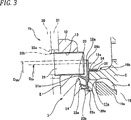
3 eine Ansicht ist, die der 2 entspricht und ein zweites Beispiel der Ausführungsform der vorliegenden Erfindung darstellt; 3 a view is that of 2 and represents a second example of the embodiment of the present invention;
4 eine Ansicht ist, die der 2 entspricht und ein drittes Beispiel darstellt; und 4 a view is that of 2 corresponds and represents a third example; and
5A und 5B Querschnittsansichten sind, die ein Beispiel eines konventionellen Aufbaus darstellen. 5A and 5B Are cross-sectional views illustrating an example of a conventional structure.
DETAILLIERTE BESCHREIBUNG DER ERFINDUNGDETAILED DESCRIPTION OF THE INVENTION
[Erstes Ausführungsbeispiel][First Embodiment]
1 und 2 zeigen ein erstes Ausführungsbeispiel der vorliegenden Erfindung. Eine radtragende Wälzlagereinheit 1a der vorliegenden Ausführungsform ist eine radtragende Wälzlagereinheit für angetriebene Räder eines üblichen Personenwagens, und umfasst einen Außenring 2, eine Nabe 3, mehrere Rollenelemente 4 und 4, mehrere Schrauben 29, einen Dichtungsring 16a und einen Kombinationsdichtungsring 28. Von diesen Elementen hat der Außenring 2 Doppelreihen-Außenringlaufflächen 5a und 5b, die auf der Innenumfangsfläche vorgesehen sind, einen stationärseitigen Flansch 6, der an dem axial in einer Zwischenposition liegenden Bereich der Außenumfangsfläche vorgesehen ist. Durchgangsbohrungen 7, durch die Schrauben zum Ankoppeln und Befestigen des Außenrings 2 an der Aufhängungseinrichtung eingeführt sind, sind an mehreren Positionen über den Umfang hinweg in dem radial in einer Zwischenposition angeordneten Bereich des stationärseitigen Flansches 6 vorgesehen. 1 and 2 show a first embodiment of the present invention. A wheel-bearing rolling bearing unit 1a In the present embodiment, a wheel-bearing rolling bearing unit for driven wheels of a conventional passenger car, and includes an outer ring 2 , a hub 3 , several rolling elements 4 and 4 , several screws 29 , a sealing ring 16a and a combination gasket 28 , Of these elements has the outer ring 2 Double-row outer ring raceways 5a and 5b provided on the inner circumferential surface, a stationary side flange 6 which is provided on the axially in an intermediate position lying portion of the outer peripheral surface. Through holes 7 , through the screws for coupling and securing the outer ring 2 are introduced at the suspension means are at a plurality of positions circumferentially in the radially arranged in an intermediate position portion of the stationary-side flange 6 intended.
Die Nabe 3 ist gebildet, indem ein Nabenhauptkörper 8 und ein Innenring 9 kombiniert werden, und sie ist auf der radial innenliegenden Seite des Außenrings 2 koaxial zu dem Außenring 2 angeordnet. Der Nabenhauptkörper 8 hat einen drehseitigen Flansch 10, der in einem Bereich der Außenumfangsflächen vorgesehen ist, die axial auf der Fahrzeugaußenseite von dem axial fahrzeugaußenseitig liegenden Ende des Außenrings 2 hervorstehen, und eine Innenringlauffläche 11a einer axial fahrzeugaußenseitigen Reihe, die in dem axial in Zwischenposition angeordneten Bereich gegenüberliegend zu der Außenringlauffläche 5a der axial fahrzeugaußenseitigen Reihe aus den Doppelreihen-Außenringlaufflächen 5a und 5a vorgesehen ist, und einen gestuften Bereich mit kleinem Durchmesser 12, der in dem axial fahrzeuginnenseitigen Ende vorgesehen ist. Schraubbohrungen 13 sind an mehreren Positionen in der Umfangsrichtung des radial in Zwischenposition angeordneten Bereichs des drehseitigen Flansches 10 vorgesehen. Ferner ist eine Keilbohrung 39 für einen keilförmigen Eingriff eines Keilschafts 38, der ein Gleichlaufgelenk 37 bildet, in dem zentralen Bereich des Nabenhauptkörpers 8 vorgesehen. Der Innenring 9 hat eine Innenringlauffläche 11b der axial fahrzeuginnenseitigen Reihe, die auf der Außenumfangsfläche davon vorgesehen ist, und ist außen an dem gestuften Bereich mit kleinem Durchmesser 12 durch Verpressen eingepasst und daran befestigt.The hub 3 is formed by a hub main body 8th and an inner ring 9 combined, and it is on the radially inner side of the outer ring 2 coaxial with the outer ring 2 arranged. The hub main body 8th has a rotating flange 10 which is provided in a portion of the outer peripheral surfaces axially on the vehicle outer side of the axially outer side of the outer ring of the outer ring 2 protrude, and an inner ring tread 11a an axially outboard-side row disposed in the axially intermediate position opposite to the outer ring raceway 5a the axially outboard row of the double row outer raceways 5a and 5a is provided, and a stepped portion of small diameter 12 which is provided in the axial vehicle inside end. screw holes 13 are at a plurality of positions in the circumferential direction of the radially intermediate portion of the rotating side flange 10 intended. Furthermore, a wedge hole 39 for a wedge-shaped engagement of a wedge shaft 38 , which is a constant velocity joint 37 forms, in the central area of the hub main body 8th intended. The inner ring 9 has an inner ring tread 11b the axially inside vehicle-side row, which is provided on the outer peripheral surface thereof, and is outside of the small-diameter stepped portion 12 fitted by pressing and attached to it.
Ferner sind mehrere Rollenelemente 4 und 4 drehbar für jede Doppelreihe so vorgesehen, dass sie zwischen den Doppelreihen-Außenringlaufflächen 5a und 5b und den Doppelreihen-Innenringlaufflächen 11a und 11b durch die Käfige bzw. Halterungen 14a und 14b gehalten werden. Im Falle des dargestellten Beispiels werden Kugeln als die Rollenelemente 4 und 4 verwendet, aber im Falle einer radtragenden Wälzlagereinheit für ein schweres Fahrzeug ist es auch möglich, eine konische Walze anstelle einer Kugel zu verwenden.Furthermore, several roller elements 4 and 4 rotatable for each double row so as to be between the double row outer ring raceways 5a and 5b and the double-row inner race treads 11a and 11b through the cages or mounts 14a and 14b being held. In the case of the illustrated example, balls are considered the roller elements 4 and 4 However, in the case of a wheel bearing rolling bearing unit for a heavy vehicle, it is also possible to use a conical roller instead of a ball.
Ferner ist jede der Schrauben 29 in der Schraubbohrung 13, die in dem drehseitigen Flansch 10 vorgesehen ist, von der axial liegenden Fahrzeugaußenseite in einem Zustand verschraubt, in welchem jede Schraube durch Befestigungsbohrungen 32a und 32b eingeführt sind, die in dem Rad 30, das das Rad bildet, und in einer Scheibe (oder einem Rotor) 31 vorgesehen sind, die als eine Bremsscheibe dient, wobei das Einführen von der axial äußeren Fahrzeugseite aus erfolgt. Bei einem derartigen Aufbau sind das Rad 30 und die Scheibe 31 an der axial fahrzeugaußenseitigen Fläche des drehseitigen Flansches 10 angekoppelt und befestigt. Im Falle dieses Beispiels stehen die Stirnbereiche (axial fahrzeuginnenseitigen Enden) der jeweiligen Schrauben 29 in der axial fahrzeuginnenseitigen Richtung aus axial fahrzeuginnenseitigen Fläche des drehseitigen Flansches hervor. Insbesondere ist die Größe des Überstands L29 der Stirnbereiche der Schrauben 29 aus der axial fahrzeuginnenseitigen Fläche des drehseitigen Flansches 10 auf 3 mm oder mehr und 5 mm oder weniger festgelegt. Jedoch kann die Größe des Überstands L29 abhängig von dem Gewicht des Fahrzeugs, dem Durchmesser (Außendurchmesser) der Räder und der Bremsscheibe und dergleichen in geeigneter Weise geändert werden. Im Falle dieses Beispiels sind als die Schrauben 29 Schrauben mit einer nominalen Größe M12 bis M14 (Außendurchmesser des Gewindebereichs beträgt 12 bis 14 mm) mit einem Feingewinde verwendet.Further, each of the screws 29 in the screw hole 13 that in the rotating flange 10 is provided bolted by the axially located vehicle outside in a state in which each screw through mounting holes 32a and 32b are introduced in the wheel 30 that forms the wheel, and in a disc (or a rotor) 31 are provided, which serves as a brake disc, wherein the insertion takes place from the axially outer side of the vehicle. In such a construction, the wheel 30 and the disc 31 on the axially vehicle outside surface of the rotating side flange 10 coupled and attached. In the case of this example, the end portions (axial vehicle inner side ends) of the respective screws are 29 in the axial direction in the vehicle inside direction from the inside of the vehicle inside surface of the rotating side flange out. In particular, the size of the protrusion L29 is the end portions of the screws 29 from the axially inside of the vehicle side surface of the rotating side flange 10 set to 3 mm or more and 5 mm or less. However, the size of the protrusion L29 may be appropriately changed depending on the weight of the vehicle, the diameter (outer diameter) of the wheels and the brake disk, and the like. In the case of this example are as the screws 29 Screws with a nominal size M12 to M14 (outer diameter of the threaded portion is 12 to 14 mm) with a fine thread used.
Der Dichtungsring 16a verschließt die Öffnung des axial fahrzeugaußenseitigen Endes des Innenraums 15, der zwischen der Innenumfangsfläche des Außenrings 2 und der Außenumfangsfläche der Nabe 3 besteht, und weist einen Metalleinsatz 17a und ein Dichtungselement 18a auf. Der Metalleinsatz 17a ist aus einer Metallplatte, etwa einer Platte aus unlegiertem Stahl bzw. Baustahl, hergestellt und hat einen Anschlusszylinderabschnitt 19a und einen Kreisringabschnitt 20a, der in radialer Richtung ausgehend von der axial fahrzeugaußenseitigen Endkante des Anschlusszylinderabschnitts 19a nach innen gebogen ist. Der Zylinderanschlussbereich 19a ist außen an der Außenumfangsfläche des axial fahrzeugaußenseitigen Endes des Außenrings 2 durch Einpressung eingepasst und daran befestigt, und die axial fahrzeuginnenseitige Fläche des radial äußeren halben Bereichs des Kreisringabschnitts 20a liegt an der axial fahrzeugaußenseitigen Stirnfläche des Außenrings 2 an. Von den Innenumfangsflächen des Anschlusszylinderabschnitts 19a in dem axial in Zwischenposition angeordneten Bereich oder einem Bereich, der näher an dem axial fahrzeuginnenseitigen Ende liegt, ist ein gestufter Bereich 35 zum Anliegen an einem Teil an einer Gießform vorgesehen, wenn das Dichtungselement 18a durch Spritzguss mit dem Metalleinsatz 17a verbunden wird.The sealing ring 16a closes the opening of the axially vehicle outside end of the interior 15 that is between the inner peripheral surface of the outer ring 2 and the outer peripheral surface of the hub 3 consists, and has a metal insert 17a and a sealing element 18a on. The metal insert 17a is made of a metal plate such as an unalloyed steel plate and has a terminal cylinder portion 19a and a circular ring section 20a in the radial direction, starting from the axial vehicle-side end edge of the terminal cylinder portion 19a bent inwards. The cylinder connection area 19a is outside of the outer peripheral surface of the axially outer side of the outer ring of the outer ring 2 fitted and fixed by press-fitting, and the axially inboard side surface of the radially outer half portion of the circular ring portion 20a lies on the axial vehicle outer side end face of the outer ring 2 at. From the inner peripheral surfaces of the terminal cylinder portion 19a in the axially intermediate portion or a region closer to the axially inboard end, is a stepped portion 35 intended to abut against a part on a casting mold when the sealing element 18a by injection molding with the metal insert 17a is connected.
Das Dichtungselement 18a ist aus einem elastischen Material, etwa einem Elastomer, etwa Gummi, hergestellt und ist durch Klebung an dem Metalleinsatz 17a durch Haftung mittels Vulkanisierung oder dergleichen befestigt und hat drei kontaktartige Dichtlippen 22a, 22b und 22c, eine Krempenlippe 33, einen überhöhten Abschnitt 26a und einen Dichtungsabschnitt 34. Von den Dichtlippen 22a bis 22c sind deren jeweiligen Stirnkanten mit der axial fahrzeuginnenseitigen Fläche des drehseitigen Flansches 10 oder der Außenumfangsfläche des in einer Zwischenposition liegenden Bereichs der Nabe 3 über den gesamten Umfang hinweg in Gleitkontakt.The sealing element 18a is made of an elastic material, such as an elastomer, such as rubber, and is adhered to the metal insert 17a attached by adhesion by vulcanization or the like and has three contact-like sealing lips 22a . 22b and 22c , a brim-lip 33 , an inflated section 26a and a sealing portion 34 , From the sealing lips 22a to 22c are their respective end edges with the axially inside of the vehicle side surface of the rotary side flange 10 or the outer peripheral surface of the intermediate position of the hub 3 in sliding contact over the entire circumference.
Die Krempenlippe 33 ist radial weiter außen zu der Dichtlippe 22a, die an der radial äußersten Seite vorgesehen ist, von den jeweiligen Dichtlippen 22a bis 22c vorgesehen und ist radial außen zu dem gestuften Bereich 24 angeordnet, der an dem Bereich nahe an dem Basisende (Bereich näher an der radial innenliegenden Seite) der axial fahrzeuginnenseitigen Fläche des drehseitigen Flansches 10 vorgesehen ist. Folglich sind der vordere halbe Teil (axial fahrzeugaußenseitige halbe Teil) der Krempenlippe 33 und der gestufte Bereich 24 so aufgebaut, dass sie in radialer Richtung überlappen. Ferner ist die Stirnkante (axial fahrzeugaußenseitige Endkante bzw. Stirnkante) der Kremperilippe 33 so gestaltet, dass sie mit kleinem Abstand der axial fahrzeuginnenseitigen Fläche des drehseitigen Flansches 10 zugewandt ist. Insbesondere ist der Abstand (der Abstand in der axialen Richtung) da zwischen der Stirnkante der Krempenlippe 33 und der axial fahrzeuginnenseitigen Fläche des drehseitigen Flansches 10 in dem Zustand, in welchem die Nabe sich nicht dreht, auf 0,5 mm oder mehr und 1,5 mm oder weniger festgelegt. In diesem Beispiel ändert sich während des Betriebs der radtragenden Wälzlagereinheit 1a (wenn sich Nabe 3 dreht) der Abstand da stark, da die Krempenlippe 33 radial außenseitig zu den jeweiligen Dichtlippen 22a bis 22c vorgesehen ist. Wenn der Abstand da kleiner als 0,5 mm ist, besteht die Möglichkeit, dass die Stirnkante der Krempenlippe 33 und die axial fahrzeuginnenseitige Fläche des drehseitigen Flansches 10 während des Betriebs der radtragenden Wälzlagereinheit 1a miteinander in Kontakt treten. Wenn andererseits der Abstand da größer als 1,5 mm ist, ist es nicht möglich, die Druckänderung, die mit einer Änderung im Luftstrom einhergeht, wenn die Außenumfangsfläche des Stirnbereichs jeder Schraube 29 vorbeiläuft, in ausreichender Weise zu erhöhen, und es besteht die Möglichkeit, dass es schwierig ist, die Wirkung des Auswerfens von Fremdmaterial, das in den radial innenliegenden Bereich der Krempenlippe 33 eindringt, in den Außenraum in ausreichender Weise zu erreichen. Die Stirnkante der Krempenlippe 33 ist so gestaltet, dass sie der axial fahrzeuginnenseitigen Fläche des drehseitigen Flansches 10 dichtliegend zugewandt ist, und somit ist eine Labyrinthdichtung 25a zwischen der Stirnkante der Krempenlippe 33 und der axial fahrzeuginnenseitigen Fläche des drehseitigen Flansches 10 vorgesehen. Der Abstand da kann in geeigneter Weise in Abhängigkeit von der axialen Abmessung der radtragenden Wälzlagereinheit 1 und dergleichen geändert werden. Es ist auch möglich, die gesamte Länge der Labyrinthdichtung 25a entsprechend zu gewährleisten, indem die Innenumfangsfläche des vorderen halben Bereichs der Krempenlippe 33 und der gestufte Bereich 24 nahe aneinander angeordnet werden. Ferner ist in diesem Beispiel die Stirnkante der Krempenlippe 33 dichtliegend der Außenumfangsfläche (der innere halbe Teil in radialer Richtung der radtragenden Wälzlagereinheit 1) eines Bereichs jeder der Schrauben 29 zugewandt, der aus der axial fahrzeuginnenseitigen Fläche des drehseitigen Flansches 10 hervorsteht. Insbesondere ist ein Abstand (Abstand in der radialen Richtung) dr zwischen der Stirnkante der Krempenlippe 33 und der Außenumfangsfläche jeder der Schrauben 29 in einem Zustand, in welchem die Nabe 3 sich nicht dreht, auf 1 mm oder größer und 3 mm oder kleiner festgelegt. Wenn der Abstand zwischen der Stirnkante der Krempenlippe 3 und der Außenumfangsfläche des Stirnbereichs jeder Schraube 29 auf kleiner als 1 mm festgelegt ist, besteht die Möglichkeit, dass die Stirnkante der Krempenlippe 33 zu der Seite der jeweiligen Schrauben 29 gezogen wird, sodass sie mit der Stirnfläche oder der Außenumfangsfläche des Stirnbereichs jeder Schraube 29 aufgrund der Druckänderung in Kontakt kommen kann, die mit einer Änderung des Luftstroms einhergeht beim Durchtritt durch die Stirnfläche und die Außenumfangsfläche des Stirnbereichs jeder Schraube 29. Wenn andererseits der Abstand zwischen der Stirnkante der Krempenlippe 33 und der Außenumfangsfläche des Stirnbereichs jeder Schraube 29 größer als 3 mm ist, ist es nicht möglich, die Druckänderung, die mit einer Änderung des Luftstroms beim Durchtritt durch die Stirnfläche und die Außenumfangsfläche des Stirnbereichs der Schraube 29 einhergeht, in ausreichender Weise zu erhöhen, und es besteht die Möglichkeit, dass es schwierig ist, die nachfolgend beschriebene Venturi-Wirkung zu erreichen. Jedoch kann der Abstand dr in geeigneter Weise in Abhängigkeit von dem Lochkreisdurchmesser jeder Schraube 29 (der Durchmesser eines Kreises, durch den der Mittelpunkt jeder Schraube 29 hindurchtritt), dem Material und dergleichen geeignet geändert werden.The brim lip 33 is radially further outward to the sealing lip 22a provided on the radially outermost side of the respective sealing lips 22a to 22c provided and is radially outward to the stepped portion 24 disposed at the area close to the base end (area closer to the radially inner side) of the axially inboard side surface of the rotating side flange 10 is provided. Consequently, the front half part (axial vehicle outer side half part) of the Krempenlippe 33 and the stepped area 24 designed so that they overlap in the radial direction. Furthermore, the front edge (axial vehicle outer side end edge or end edge) of the Kremperilippe 33 designed so that they with a small distance of the axially inside of the vehicle inside surface of the rotating side flange 10 is facing. In particular, the distance (the distance in the axial direction) is there between the end edge of the rim lip 33 and the axially inside of the vehicle side surface of the rotating side flange 10 in the state in which the hub does not rotate, set to 0.5 mm or more and 1.5 mm or less. In this example, during operation of the wheel-bearing rolling bearing unit changes 1a (if hub 3 turns) the distance there strong, since the Krempenlippe 33 radially outside to the respective sealing lips 22a to 22c is provided. If the distance is less than 0.5 mm, there is a possibility that the front edge of the Krempenlippe 33 and the axially inboard side surface of the rotating side flange 10 during operation of the wheel bearing rolling bearing unit 1a get in touch with each other. On the other hand, if the distance da is larger than 1.5 mm, it is not possible to have the pressure change accompanying a change in the air flow when the outer peripheral surface of the end portion of each screw 29 passes sufficiently to increase, and there is a possibility that it is difficult to eliminate the effect of ejecting foreign matter into the radially inner portion of the rim lip 33 penetrates to reach the outdoor space in a sufficient manner. The front edge of the brim lip 33 is designed so that it is the axial vehicle inside surface of the rotating side flange 10 is close-fitting, and thus is a labyrinth seal 25a between the front edge of the rim lip 33 and the axially inside of the vehicle side surface of the rotating side flange 10 intended. The distance da may suitably depend on the axial dimension of the wheel bearing rolling bearing unit 1 and the like are changed. It is also possible the entire length of the labyrinth seal 25a ensure accordingly by the inner peripheral surface of the front half region of the brim lip 33 and the stepped area 24 be arranged close to each other. Further, in this example, the front edge of the rim lip 33 close to the outer peripheral surface (the inner half part in the radial direction of the wheel-bearing rolling bearing unit 1 ) of a portion of each of the screws 29 facing, from the axially inside of the vehicle side surface of the rotating side flange 10 protrudes. In particular, a distance (distance in the radial direction) dr between the end edge of the Krempenlippe 33 and the outer circumferential surface of each of the screws 29 in a state in which the hub 3 does not rotate, set to 1 mm or larger and 3 mm or smaller. If the distance between the front edge of the rim lip 3 and the outer peripheral surface of the end portion of each screw 29 is set to less than 1 mm, there is a possibility that the front edge of the brim lip 33 to the side of the respective screws 29 is pulled so that it matches the end face or the outer peripheral surface of the end portion of each screw 29 may come into contact due to the change in pressure associated with a change in the air flow when passing through the end face and the outer peripheral surface of the end portion of each screw 29 , On the other hand, if the distance between the front edge of the Krempenlippe 33 and the outer peripheral surface of the end portion of each screw 29 greater than 3 mm, it is not possible to change the pressure with a change in the air flow when passing through the end face and the outer peripheral surface of the end portion of the screw 29 is accompanied by a sufficient increase, and there is the possibility that it is difficult to achieve the Venturi effect described below. However, the distance dr may suitably be dependent on the pitch circle diameter of each screw 29 (the diameter of a circle through which the center of each screw 29 passing), the material and the like are suitably changed.
Der überhöhte Abschnitt 26a geht nach außen in radialer Richtung aus dem axial fahrzeugaußenseitigen Ende des Außenrings 2 mit einem Bereich hervor, der sich radial nach außen von dem Basisende der Krempenlippe 33 in dem Dichtungselement 18a fortsetzt. Des Weiteren überlagern sich der überhöhte Abschnitt 26a und die Stirnflächen jeder Schraube 29 in der radtragenden Wälzlagereinheit (der innere halbe Teil in radialer Richtung der radtragenden Wälzlagereinheit 1) in der axialen Richtung einander überlagert, und die axial fahrzeugaußenseitige Fläche des überhöhten Abschnitts 26a und die Stirnflächen der jeweiligen Schrauben 29 sind dichtliegend einander zugewandt. Insbesondere ist der Abstand d26a zwischen der axial fahrzeugaußenseitigen Fläche des überhöhten Abschnitts 26a und der Stirnfläche jeder Schraube 29 auf 3 mm oder größer und 5 mm oder kleiner festgelegt. Wenn der Abstand d26a kleiner als 3 mm ist, dann treten die axial fahrzeugaußenseitige Fläche des überhöhten Abschnitts 26a und die Stirnflächen jeder Schraube 29 aufgrund der Druckänderung miteinander in Kontakt, die mit einer Änderung des Luftstroms beim Durchtritt durch die Stirnfläche und die Außenumfangsfläche des Stirnbereichs jeder Schraube 29 einhergeht, oder es wird ein ungewöhnliches Geräusch aufgrund der Schwingung des überhöhten Abschnitts 26a erzeugt. Wenn andererseits der Abstand d26a größer als 5 mm ist, kann die Druckänderung nicht in ausreichender Weise erhöht werden, und es besteht die Möglichkeit, dass es schwierig ist, die Venturi-Wirkung zu erreichen. Für dieses Beispiel verhindert (begrenzt) der überhöhte Abschnitt 26a, dass an der Außenumfangsfläche des Außenrings 2 anhaftende Feuchtigkeit in den Innenraum 15 entlang der Außenumfangsfläche des Außenrings 2 eindringt.The elevated section 26a goes outward in the radial direction from the axial vehicle outside end of the outer ring 2 with an area extending radially outwardly from the base end of the rim lip 33 in the sealing element 18a continues. Furthermore, the raised portion overlap 26a and the end faces of each screw 29 in the wheel bearing rolling bearing unit (the inner half part in the radial direction of the wheel bearing rolling bearing unit 1 ) are superposed on each other in the axial direction, and the axially vehicle outer side surface of the heightened portion 26a and the end faces of the respective screws 29 are close to each other. In particular, the distance d26a is between the axial vehicle outside surface of the over-elevated portion 26a and the end face of each screw 29 set to 3 mm or larger and 5 mm or smaller. If the distance d26a is smaller than 3 mm, then the axial vehicle outside-side surface of the heightened portion will enter 26a and the end faces of each screw 29 due to the pressure change in contact with each other, with a change in the air flow when passing through the end face and the outer peripheral surface of the end portion of each screw 29 is accompanied or it will be an unusual sound due to the vibration of the inflated section 26a generated. On the other hand, when the distance d26a is larger than 5 mm, the pressure change can not be sufficiently increased, and there is a possibility that it is difficult to achieve the venturi effect. For this example, the over-elevated portion prevents (limits) 26a in that on the outer peripheral surface of the outer ring 2 adhesive moisture in the interior 15 along the outer peripheral surface of the outer ring 2 penetrates.
Der Dichtungsabschnitt 34 ist so vorgesehen, dass er (die Außenumfangsfläche davon, die axial fahrzeuginnenseitige Stirnfläche und der gestufte Bereich 35) den Anschlusszylinderabschnitt 19a des Metalleinsatzes 17a mit dem Dichtungselement 18a abdeckt. Ein derartiger Dichtungsabschnitt 34 verhindert, dass an der Außenumfangsfläche des Außenrings 2 anhaftende Feuchtigkeit durch den Anschlussabschnitt zwischen der Innenumfangsfläche des Anschlusszylinderabschnitts 19a und die Außenumfangsfläche des axial äußeren Endes des Außenrings 2 in den Innenraum 15 eindringt.The sealing section 34 is provided so that it (the outer peripheral surface thereof, the axially inboard side end surface and the stepped portion 35 ) the connecting cylinder section 19a of the metal insert 17a with the sealing element 18a covers. Such a sealing portion 34 prevents on the outer peripheral surface of the outer ring 2 adhering moisture through the terminal portion between the inner peripheral surface of the terminal cylinder portion 19a and the outer peripheral surface of the axially outer end of the outer ring 2 in the interior 15 penetrates.
Ferner ist der Kombinationsdichtungsring 28 in einem Zustand vorgesehen, in welchem er die axial fahrzeuginnenseitige Endöffnung des Innenraums 15 verschließt. Further, the combination gasket ring 28 provided in a state in which he the axial vehicle inside end opening of the interior 15 closes.
Gemäß der radtragenden Wälzlagereinheit 1a des vorliegenden Beispiels, wie es zuvor beschrieben ist, ist es möglich, die Wirkung weiter zu verbessern, wonach das Eindringen von Fremdmaterial in den Innenraum 15, in welchem die Rollenelemente 4 und 4 montiert sind, verhindert wird, während die Gestaltungsfreiheit weiterhin gewährleistet ist.According to the wheel-bearing rolling bearing unit 1a of the present example, as described above, it is possible to further improve the effect, after which the intrusion of foreign matter into the interior space 15 in which the roller elements 4 and 4 are mounted, while the freedom of design is still guaranteed.
Zur Gewährleistung der Gestaltungsfreiheit werden die jeweiligen Schrauben 29 zum Halten und Fixieren des Rades 30 und der Scheibe 31 an dem drehseitigen Flansch 10 in den Schraubbohrungen 13 des drehseitigen Flansches 10 von der axial Fahrzeugaußenseite in dem Zustand verschraubt, in welchem sie durch die Befestigungsbohrungen 32a und 32b des Rades 30 und der Scheibe 31 eingeführt sind. Das heißt, in dem Fall dieses Beispiels sind die Stirnbereiche der jeweiligen Schrauben 29 so ausgebildet, dass sie ausgehend von der axial fahrzeuginnenseitigen Fläche des drehseitigen Flansches 10 axial nach innen hervorstehen. Jedoch wird wie bei dem in der JP-A-2009-132207 offenbarten Struktur verhindert, dass der Betrag des Überstands L29 kleiner ist als der Betrag des Überstands der jeweiligen Stifte in Bezug zu der axial fahrzeuginnenseitigen Fläche des drehseitigen Flansches in dem Aufbau, in welchem das Rad und die Bremsscheibe durch den Stift mit dem drehseitigen Flansch gekoppelt und an diesem befestigt sind. Daher ist es im Falle dieses Beispiels nicht erforderlich, die Stirnbereiche der jeweiligen Schrauben 29 und das axial fahrzeugaußenseitige Ende des Außenrings 2 so zu gestalten, dass sie in radialer Richtung überlappen. Da der Außendurchmesser der Stirnbereiche jeder Schraube 29 kleiner ist als der Außendurchmesser des Stiftes, kann der Außendurchmesser des axial fahrzeugaußenseitigen Endes des Außenrings 2 größer sein als derjenige des in JP-A-2009-132207 beschriebener Aufbaus, selbst wenn die Stirnbereiche der jeweiligen Schrauben 29 und das axial fahrzeugaußenseitige Ende des Außenrings 2 so hergestellt sind, dass sie in radialer Richtung überlappen. In jedem Falle kann gemäß der radtragenden Wälzlagereinheit 1a des vorliegenden Beispiels die Gestaltungsfreiheit verbessert und der Krümmungsradius der Außenringlauffläche 5a der axial fahrzeugaußenseitigen Reihe im Vergleich zu dem in JP-A-2009-132207 beschriebenen Aufbau vergrößert werden. Daher ist es möglich, die Lebensdauer im Hinblick auf Rollenermüdung und die Momentensteifigkeit zu verbessern. Da es unnötig ist, eine Auflagefläche bereitzustellen, um die axial fahrzeugaußenseitige Fläche des Kopfes des Stiftes mit der axial fahrzeuginnenseitigen Fläche des drehseitigen Flansches 10 in Kontakt zu bringen, ist es ferner in diesem Beispiel möglich, die radiale Dicke des radial in Zwischenposition angeordneten Bereichs des drehseitigen Flansches 10 zu vergrößern, und es ist möglich, die Festigkeit und die Steifigkeit des drehseitigen Flansches 10 zu verbessern.To ensure freedom of design, the respective screws 29 for holding and fixing the wheel 30 and the disc 31 on the rotating side flange 10 in the screw holes 13 the rotating flange 10 bolted from the axial vehicle outside in the state in which they through the mounting holes 32a and 32b of the wheel 30 and the disc 31 are introduced. That is, in the case of this example, the end portions of the respective screws 29 formed so that it starts from the axially inside of the vehicle side surface of the rotary side flange 10 protrude axially inward. However, like the one in the JP-A-2009-132207 disclosed structure prevents the amount of the protrusion L29 is smaller than the amount of protrusion of the respective pins with respect to the axially inboard side surface of the rotary side flange in the structure in which the wheel and the brake disc coupled by the pin with the rotating side flange and attached to this. Therefore, in the case of this example, it is not necessary to have the end portions of the respective screws 29 and the axial vehicle outside end of the outer ring 2 be designed so that they overlap in the radial direction. Because the outside diameter of the frontal areas of each screw 29 is smaller than the outer diameter of the pin, the outer diameter of the axially outer side of the outer ring of the outer ring 2 larger than that of the structure described in JP-A-2009-132207, even if the end portions of the respective screws 29 and the axial vehicle outside end of the outer ring 2 are made so that they overlap in the radial direction. In any case, according to the wheel-bearing rolling bearing unit 1a of the present example improves the freedom of design and the radius of curvature of the outer raceway surface 5a of the axial vehicle outside-side row are increased as compared with the structure described in JP-A-2009-132207. Therefore, it is possible to improve the life in terms of rolling fatigue and the torque rigidity. Since it is unnecessary to provide a bearing surface around the axially vehicle outer side surface of the head of the pin with the axially inboard side surface of the rotating side flange 10 Further, in this example, it is possible to adjust the radial thickness of the radially intermediate portion of the rotational side flange 10 To increase, and it is possible, the strength and rigidity of the rotating side flange 10 to improve.
Wenn die radtragende Wälzlagereinheit 1a in Betrieb ist, sind die jeweiligen Schrauben 29, die von dem drehseitigen Flansch 10 gehalten werden, in Drehung (im Umlauf) um die Mittelachse der Nabe 3 bei Drehung der Nabe 3. Wenn die Schrauben 29 in Drehung sind, wird ein Luftstrom zwischen den Stirnflächen und (dem inneren Halbteil in radialer Richtung der Nabe 3 davon), den Außenumfangsflächen des Stirnbereichs der Schrauben 29 und der axial fahrzeugaußenseitigen Fläche des überhöhten Abschnitts 26a und der Außenumfangsfläche der Krempenlippe 33 erzeugt. Wie sich aus dem Bernoullischen Theorem ergibt, wird Fremdmaterial, das an der Außenumfangsfläche der Krempenlippe 33 anhaftet, aufgrund des Luftstroms, der während der Fahrt des Fahrzeugs entsteht, eine hohe Geschwindigkeit und einen geringen Druck hat, zur Seite der jeweiligen Schrauben 29 hin angezogen und wird durch die Wirkung der Zentrifugalkraft in den Außenraum abgeführt. Wenn ferner die Stirnfläche und die Außenumfangsfläche des Stirnbereichs jeder Schraube 29 durch die axial fahrzeugaußenseitige Fläche des überhöhten Abschnitts 26a und die Außenumfangsfläche der Krempenlippe 33 treten, wird aufgrund des Venturi-Effekts der Luftstrom durch diesen Bereich (der Bereich, durch den die Stirnfläche und die Außenumfangsfläche des Stirnbereichs jeder Schraube 29 verlaufen) beschleunigt. Durch die Wirkung des beschleunigten Luftstroms wird das Fremdmaterial, das in den radial fahrzeuginnenseitigen Bereich (ein Ringraum zwischen der Innenumfangsfläche der Krempenlippe 33 und der Außenumfangsfläche der Dichtlippe 22a, die auf der äußersten Seite vorgesehen ist) der Krempenlippe 33 eingedrungen ist, in den Außenraum abgeführt. Folglich ist es möglich, die Wirkung zu verbessern, wonach das Eindringen von Fremdmaterial in den Innenraum 15 im Vergleich zu dem konventionellen Aufbau, der in 5A und 5B gezeigt und zuvor beschrieben ist, verhindert wird.When the wheel bearing rolling bearing unit 1a in operation, are the respective screws 29 from the rotating flange 10 held in rotation around the central axis of the hub 3 upon rotation of the hub 3 , If the screws 29 are in rotation, an air flow between the end faces and (the inner half part in the radial direction of the hub 3 thereof), the outer peripheral surfaces of the end portion of the screws 29 and the axially vehicle outside surface of the over-elevated portion 26a and the outer circumferential surface of the brim lip 33 generated. As can be seen from the Bernoulli theorem, foreign material is deposited on the outer peripheral surface of the brim lip 33 adheres due to the air flow generated during the running of the vehicle, a high speed and a low pressure, to the side of the respective screws 29 attracted and is dissipated by the action of centrifugal force in the outer space. Further, when the end surface and the outer peripheral surface of the end portion of each screw 29 through the axially vehicle outer side surface of the inflated portion 26a and the outer circumferential surface of the brim lip 33 due to the Venturi effect, the air flow through this area (the area through which the end face and the outer peripheral face of the end portion of each screw 29 run) accelerates. By the action of the accelerated air flow, the foreign matter entering into the radially inward vehicle area (an annular space between the inner peripheral surface of the rim lip 33 and the outer peripheral surface of the sealing lip 22a provided on the outermost side) of the brim lip 33 has penetrated, discharged into the outer space. Consequently, it is possible to improve the effect, according to which the intrusion of foreign material into the interior space 15 in comparison to the conventional construction, which in 5A and 5B shown and described above, is prevented.
Ferner kann bei der Umsetzung der vorliegenden Erfindung, wie in dem konventionellen Aufbau, der in 5A und 5B dargestellt ist, der Dichtungsring zum Verschließen der Öffnung an dem axial fahrzeugaußenseitigen Ende des Innenraums 15 so gebildet werden, dass der Anschlusszylinderabschnitt des Metalleinsatzes intern an die Innenumfangsfläche des axial fahrzeugaußenseitigen Endes des Außenrings durch Verpressung eingepasst und befestigt wird, und die axial fahrzeuginnenseitige Fläche des Kreisringabschnitts, der ausgehend von der axial fahrzeugaußenseitigen Endkante des Anschlusszylinderabschnitts radial nach außen gebogen ist, liegt an der axial fahrzeugaußenseitigen Stirnfläche des Außenrings an.Further, in the practice of the present invention, as in the conventional structure, shown in FIG 5A and 5B is shown, the sealing ring for closing the opening at the axially vehicle outside end of the interior 15 be formed so that the terminal cylinder portion of the metal insert is internally press fitted and fixed to the inner peripheral surface of the axially outer side end of the outer ring, and the axially inner side surface of the annular portion, the radially outwardly from the axially outer side end edge of the terminal cylinder portion is bent, abuts the axial vehicle outer side end face of the outer ring.
Des Weiteren kann die vorliegende Erfindung auch auf eine radtragende Wälzlagereinheit angewendet werden, in der eine Nabe für feste nicht angetriebene Räder verwendet wird, ohne auf die radtragende Wälzlagereinheit für ein angetriebenes Rad eingeschränkt zu sein, das mit einer Eingriffsbohrung, etwa einer Keilbohrung versehen ist, um mit einer Antriebswelle im Eingriff zu sein, die Teil eines Gleichlaufgelenks für den zentralen Bereich der Nabe ist, um Leistung zu übertragen. Wenn die vorliegende Erfindung auf die radtragende Wälzlagereinheit für ein nicht angetriebenes Rad angewendet wird, kann die Öffnung des axial fahrzeuginnenseitigen Endes des Innenraums, der zwischen der Innenumfangsfläche des Außenrings und der Außenumfangsfläche der Nabe besteht, auch so gestaltet sein, dass sie durch eine bodenseitige Zylinderabdeckung geschlossen ist, die an das axial fahrzeuginnenseitige Ende des Außenrings eingepasst und daran befestigt ist.Further, the present invention can also be applied to a wheel-supporting rolling bearing unit in which a hub for fixed non-driven wheels is used without being limited to the wheel-bearing driven-roller bearing unit provided with an engaging hole such as a tapered hole. to engage a drive shaft that is part of a constant velocity joint for the central area of the hub to transmit power. When the present invention is applied to the wheel-supporting non-driven-wheel rolling bearing unit, the opening of the axially inboard side end of the inner space existing between the inner peripheral surface of the outer race and the outer peripheral surface of the hub may also be configured to pass through a bottomed cylinder cover is closed, which is fitted to the axial vehicle inside end of the outer ring and attached thereto.
Des Weiteren ist die vorliegende Erfindung nicht auf den Aufbau beschränkt, in welchem die Lochkreisdurchmesser von Rollenelementen der beiden Reihen gleich sind, sondern die vorliegende Erfindung kann auch auf eine sogenannte asymmetrische radtragende Wälzlagereinheit angewendet werden, in der die Lochkreisdurchmesser der Rollenelemente beider Reihen unterschiedlich zueinander sind (die Lochkreisdurchmesser der Rollenelemente in der axial fahrzeugaußenseitigen Reihe sind größer oder kleiner als der Lochkreisdurchmesser der axial fahrzeuginnenseitigen Reihe).Furthermore, the present invention is not limited to the structure in which the pitch circle diameters of roller members of the two rows are the same, but the present invention can be applied to a so-called asymmetric wheel bearing rolling bearing unit in which the pitch circle diameters of the roller members of both rows are different from each other (The pitch circle diameter of the rolling elements in the axial vehicle outside-side row are larger or smaller than the pitch circle diameter of the axially inboard side row).
[Zweites Ausführungsbeispiel]Second Embodiment
3 zeigt ein zweites Ausführungsbeispiel der vorliegenden Erfindung. In der radtragenden Wälzlagereinheit 1b dieses Beispiels ist der Außendurchmesser D26b des überhöhten Abschnitts 26b des Dichtungsrings 16b zum Verschluss der Öffnung des axial fahrzeugaußenseitigen Endes des Innenraums 15 größer als der Lochkreisdurchmesser D29 der mehreren Schrauben 29 (D26b > D29). Gemäß diesem Beispiel kann, wie zuvor beschrieben ist, der Betrag der Beschleunigung (Betrag der Geschwindigkeitszunahme) des Luftstroms, wenn Stirnflächen der jeweiligen Schrauben 29 durch die axial fahrzeugaußenseitige Fläche des überhöhten Abschnitts 26a treten, größer sein als derjenige des Aufbaus des ersten zuvor genannten Ausführungsbeispiels, und es ist möglich, die ableitende Wirkung für Fremdmaterial aus dem radial innenliegenden Bereich der Krempenlippe 33 weiter zu verbessern. 3 shows a second embodiment of the present invention. In the wheel-bearing rolling bearing unit 1b This example is the outer diameter D26b of the over-elevated portion 26b of the sealing ring 16b for closing the opening of the axial vehicle outside end of the interior 15 larger than the pitch circle diameter D29 of the multiple screws 29 (D26b> D29). According to this example, as described above, the amount of acceleration (amount of speed increase) of the airflow when faces of the respective screws 29 through the axially vehicle outer side surface of the inflated portion 26a be greater than that of the structure of the first embodiment mentioned above, and it is possible, the discharging effect for foreign material from the radially inner region of the Krempenlippe 33 continue to improve.
Der Aufbau und die Funktionsweise der anderen Teile sind gleich zu jenen des ersten Ausführungsbeispiels.The structure and operation of the other parts are the same as those of the first embodiment.
[Drittes Ausführungsbeispiel][Third Embodiment]
4 zeigt ein drittes Beispiel der Ausführungsform der vorliegenden Erfindung. In einer radtragenden Wälzlagereinheit 1c dieses Beispiels ist der überhöhte Abschnitt 26c eines Dichtungsrings 16c, der die Öffnung des axial fahrzeugaußenseitigen Endes des Innenraums 15 verschließt, durch einen Teil des Metalleinsatzes 17b verstärkt. Das heißt, der Metalleinsatz 17b ist so ausgebildet, dass er einen Anschlusszylinderabschnitt 19b, einen axial fahrzeuginnenseitigen Kreisringabschnitt 36, der in radialer Richtung ausgehend von der axial fahrzeugaußenseitigen Stirnkante des Anschlusszylinderabschnitts 19b nach außen gebogen ist, und einen Kreisringabschnitt 20b aufweist, der in U-Form ausgehend von der radial äußeren Stirnkante des radial fahrzeuginnenseitigen Kreisringabschnitts 36 in Richtung der radial nach innen zeigenden Richtung zurückgefaltet ist. Der überhöhte Abschnitt 26c ist in einem Zustand vorgesehen, in welchem er den axial fahrzeuginnenseitigen Kreisringabschnitt 36 und das radial äußere Ende des Kreisringabschnitts 20b von der radial äußeren Seite und den beiden axialen Seiten her abdeckt. Der Dichtungsring 16c wird von dem Außenring 2 gehalten und ist an diesem befestigt derart, dass der Anschlusszylinderabschnitt 19b des Metalleinsatzes 17b durch Verpressung von außen an die Außenumfangsfläche des axial fahrzeugaußenseitigen Endes des Außenrings 2 angepasst und dort befestigt ist, und der radial in Zwischenposition angeordnete Bereich des Kreisringabschnitts 20b ist so gestaltet, dass er an der axial fahrzeugaußenseitigen Stirnfläche des Außenrings 2 anliegt. 4 shows a third example of the embodiment of the present invention. In a wheel-bearing rolling bearing unit 1c of this example is the raised portion 26c a sealing ring 16c that the opening of the axial vehicle outside end of the interior 15 closes, by a part of the metal insert 17b strengthened. That is, the metal insert 17b is formed so that it has a connecting cylinder section 19b , an axial inside of the vehicle circular ring section 36 in the radial direction, starting from the axial vehicle-side end edge of the terminal cylinder portion 19b bent outward, and a circular ring section 20b has, in U-shape, starting from the radially outer end edge of the radially inner side of the inner annular portion 36 folded back in the direction of the radially inward direction. The elevated section 26c is provided in a state in which it is the axial vehicle inner side annulus section 36 and the radially outer end of the annulus section 20b from the radially outer side and the two axial sides covers. The sealing ring 16c is from the outer ring 2 held and is attached to this such that the connecting cylinder section 19b of the metal insert 17b by compression from the outside to the outer peripheral surface of the axial vehicle outer side end of the outer ring 2 adapted and fixed there, and the radially arranged in intermediate position region of the circular ring section 20b is configured so that it on the axial vehicle outer side end face of the outer ring 2 is applied.
Gemäß diesem zuvor beschriebenen Beispiel ist es möglich, in zuverlässiger Weise eine Situation zu verhindern, in der aufgrund des Einflusses des Luftstroms, der während des Betriebs der radtragenden Wälzlagereinheit 1c erzeugt wird, der überhöhte Abschnitte 26c zu den mehreren Schrauben 29 gezogen wird, die von dem drehseitigen Flansch 10 gehalten werden, der überhöhte Abschnitt 26c und die Stirnflächen der jeweiligen Schrauben 29 miteinander in Kontakt treten, oder der überhöhte Abschnitt 26c in Schwingung gerät, sodass ungewöhnliche Geräusche erzeugt werden.According to this example described above, it is possible to reliably prevent a situation in which due to the influence of the air flow occurring during operation of the wheel-bearing rolling bearing unit 1c is generated, the elevated sections 26c to the several screws 29 being pulled, that of the rotating side flange 10 be held, the elevated section 26c and the end faces of the respective screws 29 contact each other, or the elevated portion 26c vibrates to produce unusual sounds.
Die Strukturen und Funktionen der anderen Teile sind gleich zu jenen des ersten und des zweiten zuvor genannten Ausführungsbeispiels.
Liste der BezugszeichenThe structures and functions of the other parts are the same as those of the first and second aforementioned embodiments.
List of reference numbers
ZITATE ENTHALTEN IN DER BESCHREIBUNG QUOTES INCLUDE IN THE DESCRIPTION
Diese Liste der vom Anmelder aufgeführten Dokumente wurde automatisiert erzeugt und ist ausschließlich zur besseren Information des Lesers aufgenommen. Die Liste ist nicht Bestandteil der deutschen Patent- bzw. Gebrauchsmusteranmeldung. Das DPMA übernimmt keinerlei Haftung für etwaige Fehler oder Auslassungen.This list of the documents listed by the applicant has been generated automatically and is included solely for the better information of the reader. The list is not part of the German patent or utility model application. The DPMA assumes no liability for any errors or omissions.
Zitierte PatentliteraturCited patent literature
-
JP 2009-132207 A [0002, 0024, 0043] JP 2009-132207 A [0002, 0024, 0043]
-
JP 2014-142054 A [0002, 0004, 0011] JP 2014-142054 A [0002, 0004, 0011]