Technisches GebietTechnical area
Die Erfindung bezieht sich auf Fremdkörpersammel- und Metrologievorrichtungen, sowie auf Teilchensammel- und Metrologiesysteme. Insbesondere bezieht sich die Erfindung auf Vorrichtungen und Systeme für die Entfernung von Fremdkörpern während und/oder nach Nanobearbeitungsprozessen. Außerdem können die erfindungsgemäßen Vorrichtungen und Systeme für das Entfernen von etwas beliebigem fremden von einem Substrat angewendet werden.The invention relates to foreign body collection and metrology devices, as well as particle collection and metrology systems. In particular, the invention relates to devices and systems for the removal of foreign bodies during and / or after nano-machining processes. In addition, the devices and systems of the invention can be used for the removal of any foreign matter from a substrate.
Hintergrundbackground
Die Nanobearbeitung beinhaltet definitionsgemäß ein mechanisches Entfernen von Materialvolumen im Nanometerbereich, beispielsweise von einer Fotolithografiemaske, einem Halbleitersubstrat/Wafer oder einer beliebigen Oberfläche, auf der die Rastersondenmikroskopie (SPM, im Englischen: „scanning probe microscopy“) durchgeführt werden kann. Für die Zwecke dieser Erörterung bezieht sich „Substrat“ auf ein beliebiges Objekt, an dem eine Nanobearbeitung durchgeführt werden kann.By definition, nano-processing includes the mechanical removal of material volumes in the nanometer range, for example from a photolithography mask, a semiconductor substrate / wafer or any surface on which scanning probe microscopy (SPM) can be carried out. For the purposes of this discussion, “substrate” refers to any object on which nano-machining can be performed.
Beispiele für Fotolithografiemasken umfassen: Standardfotomasken (193 nm Wellenlänge, mit oder ohne Immersion), Lithografiemasken der nächsten Generation (Prägelithografie, gerichtete Selbstassemblierung usw.), Fotomasken für die Extremultraviolettlithografie (EUV oder EUVL) und jede beliebige andere praktikable oder nützliche Maskentechnologie. Beispiele für andere Oberflächen, die als Substrate angesehen werden, sind Membranen, Pellikelfolien, mikroelektronische/nanoelektronische mechanische Systeme MEMS/NEMS. Die Verwendung der Begriffe „Maske“ oder „Substrat“ in der vorliegenden Offenbarung umfasst die obigen Beispiele, obwohl von den Fachleuten verstanden werden wird, dass auch andere Fotomasken oder Oberflächen verwendbar sein können.Examples of photolithography masks include: standard photomasks (193 nm wavelength, with or without immersion), next generation lithography masks (embossed lithography, directional self-assembly, etc.), photomasks for extreme ultraviolet lithography (EUV or EUVL), and any other practical or useful mask technology. Examples of other surfaces that are viewed as substrates are membranes, pellicle films, microelectronic / nanoelectronic mechanical systems MEMS / NEMS. The use of the terms “mask” or “substrate” in the present disclosure encompasses the above examples, although it will be understood by those skilled in the art that other photomasks or surfaces may also be used.
In der verwandten Technik kann die Nanobearbeitung durchgeführt werden, indem auf eine Oberfläche eines Substrats mit einer Spitze (beispielsweise einem Diamantfräser), die auf einem Cantileverarm eines Rasterkraftmikroskops (AFM, im Englischen: „atomic force microscope“) angeordnet ist, Kräfte ausgeübt werden. Insbesondere kann die Spitze zuerst in die Oberfläche des Substrats hineingesteckt werden, und dann kann die Spitze in einer Ebene, die parallel zur Oberfläche (d. h., der xy-Ebene) ist, durch das Substrat gezogen werden. Das führt zu einer Verlagerung und/oder einem Entfernen von Material vom Substrat, während die Spitze vorwärts gezogen wird.In the related art, nano-machining can be performed by applying forces to a surface of a substrate with a tip (e.g., a diamond cutter) placed on a cantilever arm of an atomic force microscope (AFM). In particular, the tip can first be stuck into the surface of the substrate and then the tip can be pulled through the substrate in a plane that is parallel to the surface (i.e., the xy plane). This results in displacement and / or removal of material from the substrate as the tip is pulled forward.
Als ein Resultat dieser Nanobearbeitung werden Fremdkörper (womit etwas beliebiges Fremdes auf der Oberfläche des Substrats umfasst ist) auf dem Substrat erzeugt. Insbesondere können sich während des Nanobearbeitungsprozesses kleine Teilchen bilden, wenn von dem Substrat Material entfernt wird. Diese Teilchen bleiben in manchen Fällen auf dem Substrat, sobald der Nanobearbeitungsprozess abgeschlossen ist. Solche Teilchen finden man oft beispielsweise in Gräben und/oder Hohlräumen, die auf dem Substrat vorhanden sind.As a result of this nano-processing, foreign objects (which includes anything foreign on the surface of the substrate) are generated on the substrate. In particular, small particles can form during the nano-machining process when material is removed from the substrate. In some cases, these particles remain on the substrate once the nano-machining process is complete. Such particles are often found, for example, in trenches and / or cavities that are present on the substrate.
Um Fremdkörper, Teilchen oder irgendetwas dem Substrat fremdes zu entfernen, wurden insbesondere für Strukturen von Fotolithografiemasken mit hohem Aspektverhältnis und elektronische Schaltungen Techniken der Nassreinigung verwendet. Insbesondere können die Anwendung von Chemikalien in einem flüssigen Zustand und/oder eine Agitation der gesamten Maske oder des gesamten Schaltkreises verwendet werden. Sowohl chemische Verfahren als auch Agitationsverfahren, wie beispielsweise die Megaschallagitation, können jedoch sowohl Strukturen mit hohem Aspektverhältnis als auch Elemente für die optische Nahbereichskorrektur (d. h., Elemente, die im Allgemeinen so klein sind, dass diese Elemente nicht abgebildet werden, sondern stattdessen Beugungsmuster erzeugen, die von Maskendesignern in vorteilhafter Weise für die Erzeugung von Mustern verwendet werden) nachteilig verändern oder zerstören.In order to remove foreign bodies, particles or anything foreign to the substrate, wet cleaning techniques have been used, particularly for structures of photolithography masks with a high aspect ratio and electronic circuits. In particular, the application of chemicals in a liquid state and / or agitation of the entire mask or the entire circuit can be used. Both chemical processes and agitation processes, such as megasonic agitation, can, however, both structures with a high aspect ratio and elements for optical close-range correction (i.e., elements that are generally so small that these elements are not imaged, but instead generate diffraction patterns, which are used by mask designers in an advantageous manner for the generation of patterns) disadvantageously change or destroy.
Um besser zu verstehen, warum Formen und Strukturen mit hohem Aspektverhältnis besonders anfällig dafür sind, durch Chemikalien und Agitation zerstört zu werden, muss man sich daran erinnern, dass solche Formen und Strukturen definitionsgemäß einen großen Oberflächeninhalt haben und deshalb thermodynamisch sehr instabil sind. Diese Formen und Strukturen sind als solche sehr anfällig für eine Ablösung und/oder andere Arten der Zerstörung, wenn chemische und/oder mechanische Energie angewendet wird.To better understand why shapes and structures with a high aspect ratio are particularly susceptible to being destroyed by chemicals and agitation, one must remember that such shapes and structures by definition have a large surface area and are therefore very thermodynamically unstable. As such, these shapes and structures are very susceptible to delamination and / or other types of destruction when chemical and / or mechanical energy is applied.
Es ist wichtig, zu erwähnen, dass es bei der Prägelithografie und der EUV (oder EUVL) derzeit nicht möglich ist, ein Pellikel zu verwenden, um Teilchen von der zu kopierenden Lithografiefläche fernzuhalten. Techniken, bei denen keine Pellikel verwendet werden können, sind im Allgemeinen anfälliger für Fehler, die durch eine Verunreinigung mit Teilchen verursacht werden, die die Möglichkeit, das Muster auf den Wafer zu übertragen, blockiert. Für EUV-Masken sind Pellikel in Entwicklung, aber die bisherige Erfahrung mit DUV-Pellikelmasken weist darauf hin, dass die Verwendung eines Pellikels das Fallen kritischer Teilchen und anderer Verunreinigungen auf die Oberfläche nur abschwächt (aber nicht vollständig verhindert) und jede anschließende Bestrahlung mit den hochenergetischen Photonen wird dazu neigen, diese Teilchen mit einem höheren Grad an Anhaftung an der Maskenoberfläche zu fixieren. Außerdem können diese Technologien mit kleineren Strukturgrößen (1 bis 300 nm) implementiert werden, wodurch sie für Beschädigungen während üblicher Nassreinigungsmethoden, die typischerweise angewendet werden können, anfälliger werden. In dem speziellen Fall der EUV oder EUVL kann die Technologie erfordern, dass sich das Substrat während der Verwendung und wahrscheinlich auch während der Aufbewahrung vor der Verwendung in einer Vakuumumgebung befindet. Um übliche Nassreinigungstechnologien zu verwenden, müsste dieses Vakuum aufgehoben werden, was leicht zu einer weiteren Verunreinigung mit Teilchen führen könnte.It is important to note that with embossing lithography and EUV (or EUVL) it is not currently possible to use a pellicle to keep particles away from the lithographic surface to be copied. Techniques that do not use pellicles are generally more prone to failure caused by particle contamination that blocks the ability to transfer the pattern onto the wafer. Pellicles are under development for EUV masks, but previous experience with DUV pellicle masks indicates that using a pellicle only mitigates (but does not completely prevent) the fall of critical particles and other contaminants onto the surface and any subsequent exposure to the high energy photons will tend to fix these particles to the mask surface with a higher degree of attachment. In addition, these technologies can be implemented with smaller feature sizes (1 to 300 nm), making them more susceptible to damage during common wet cleaning methods that can typically be used. In the specific case of the EUV or EUVL, the technology may require that the substrate be in a vacuum environment during use and probably also during storage prior to use. In order to use conventional wet cleaning technologies, this vacuum would have to be broken, which could easily lead to further contamination with particles.
In anderen derzeit verfügbaren Verfahren zum Entfernen von Verunreinigungen von einem Substrat werden kryogene Reinigungssysteme und -techniken verwendet. Beispielsweise kann das Substrat, das die Formen und/oder Strukturen mit hohem Aspektverhältnis enthält, in wirksamer Weise „sandgestrahlt“ werden, wobei anstelle von Sand Kohlendioxidteilchen verwendet werden.Other methods currently available for removing contaminants from a substrate use cryogenic cleaning systems and techniques. For example, the substrate containing the high aspect ratio shapes and / or structures can be effectively "sandblasted" using carbon dioxide particles instead of sand.
Es ist jedoch bekannt, dass sogar kryogene Reinigungssysteme und -prozesse gemäß der verwandten Technik Strukturelemente mit hohem Aspektverhältnis in nachteiliger Weise verändern oder zerstören können. Außerdem beeinflussen kryogene Reinigungsprozesse einen relativ großen Bereich eines Substrats (z. B. können die für die Säuberung von Verunreinigungen mit Abmessungen in der Größenordnung von Nanometern behandelten Flächen einen Durchmesser von ungefähr 10 Millimeter oder mehr haben). Infolgedessen werden Bereiche des Substrats, von denen möglicherweise keine Fremdkörper entfernt werden müssen, trotzdem dem kryogenen Reinigungsprozess und den damit verbundenen, möglicherweise die Strukturen zerstörenden Energien ausgesetzt. Es wird angemerkt, dass es zahlreiche physikalische Unterschiede zwischen dem Nano- und dem Mikrobereich gibt, und dass für die hiesigen Zwecke der Fokus auf den Unterschieden, die einen Bezug zu Reinigungsverfahren für Nanoteilchen haben, liegen wird. Es gibt viele Ähnlichkeiten zwischen Reinigungsprozessen im Nanobereich und im Makrobereich, aber auch viele kritische Unterschiede. Für die Zwecke dieser Offenbarung ist die allgemeine Definition des Nanobereichs von Nutzen: dieser definiert einen Größenbereich von 1 bis 100 nm. Dies ist ein verallgemeinerter Bereich, da viele der hier besprochenen Prozesse unterhalb dieses Bereichs (bis in den atomaren Bereich hinein) auftreten können, und dazu in der Lage sein können, Teilchen, die größer als dieser Bereich sind (bis in den Mikrobereich hinein) zu beeinflussen.However, it is known that even cryogenic cleaning systems and processes according to the related art can adversely alter or destroy structural elements with high aspect ratios. In addition, cryogenic cleaning processes affect a relatively large area of a substrate (e.g., the areas treated to clean contaminants with dimensions on the order of nanometers can be approximately 10 millimeters or more in diameter). As a result, areas of the substrate from which it is possible that no foreign bodies have to be removed are nevertheless exposed to the cryogenic cleaning process and the associated energies which may destroy the structures. It is noted that there are numerous physical differences between the nano and the micro range and that for purposes here the focus will be on the differences related to nanoparticle cleaning methods. There are many similarities between cleaning processes in the nano-range and in the macro-range, but also many critical differences. For the purposes of this disclosure, the general definition of the nanoscale is useful: it defines a size range from 1 to 100 nm. This is a generalized range as many of the processes discussed here can occur below this range (down to the atomic level), and may be able to influence particles that are larger than this range (down to the micro range).
Einige physikalische Unterschiede zwischen Reinigungsprozessen für Makro- und Nanoteilchen umfassen transportbezogene Eigenschaften, die den Flächeninhalt, die mittlere freie Weglänge, thermische und Feldeffekte umfassen. Die ersten beiden Elemente in dieser Liste sind eher für das thermisch-mechanisch-chemische Verhalten von Teilchen relevant, während das letzte eher für die Wechselwirkung von Teilchen mit elektromagnetischen Feldern von Bedeutung ist. Das Phänomen des thermischen Transports überschneidet insofern beide dieser Bereiche, als es auch die thermo-mechanische physikalische Chemie um die Teilchen herum und die Wechselwirkung von Teilchen mit elektromagnetischen Feldern im infraroten Wellenlängenbereich betrifft. Um einige dieser Unterschiede funktionell darzustellen, wird als ein Beispiel für ein Gedankenexperiment ein Nanoteilchen postuliert, das am Boden einer Linien- und Raumstruktur mit hohem Aspektverhältnis (70 nm tief und 40 nm breit ~ AR = 1,75) gefangen ist. Um dieses Teilchen mit Prozessen auf der Makroskala abzureinigen, ist die Energie, die benötigt wird, um das Teilchen zu entfernen, ungefähr gleich groß wie die Energie, die benötigt wird, um Strukturelemente oder Muster auf dem Substrat zu beschädigen, wodurch es unmöglich wird, die Linien- und Raumstruktur mit hohem Aspektverhältnis ohne Beschädigung zu reinigen. Bei Reinigungsprozessen auf der Makroskala (wässrig, Tensid, Schallagitation usw.) wird bei dem Energieniveau, bei dem das Nanoteilchen entfernt wird, auch das umgebende Strukturelement oder Muster beschädigt. Wenn man die technische Fähigkeit hat, nanoscharfe Strukturen (oder solche im Nanobereich) innerhalb von Nanoabständen zum Nanoteilchen genau zu manipulieren, kann man die Energie, die dafür notwendig ist, das Nanoteilchen abzureinigen, ausschließlich dem Nanoteilchen zuführen. Für Reinigungsprozesse im Nanobereich wird die Energie, die dafür notwendig ist, das Nanoteilchen zu entfernen, nur dem Nanoteilchen zugeführt und nicht den umgebenden Strukturelementen oder Mustern auf dem Substrat.Some physical differences between macro- and nano-particle cleaning processes include transport-related properties that include surface area, mean free path, thermal and field effects. The first two elements in this list are more relevant to the thermo-mechanical-chemical behavior of particles, while the last is more relevant to the interaction of particles with electromagnetic fields. The phenomenon of thermal transport overlaps both of these areas in that it also affects the thermo-mechanical physical chemistry around the particles and the interaction of particles with electromagnetic fields in the infrared wavelength range. In order to functionally illustrate some of these differences, a nanoparticle is postulated as an example of a thought experiment, which is trapped at the bottom of a line and space structure with a high aspect ratio (70 nm deep and 40 nm wide ~ AR = 1.75). In order to clean up this particle with processes on the macro scale, the energy required to remove the particle is roughly the same as the energy required to damage structural elements or patterns on the substrate, making it impossible to clean the line and spatial structure with a high aspect ratio without damaging it. In cleaning processes on the macro scale (aqueous, surfactant, sonic agitation, etc.), the surrounding structural element or pattern is also damaged at the energy level at which the nanoparticle is removed. If you have the technical ability to manipulate nano-sharp structures (or those in the nanoscale) precisely within nano-distances to the nanoparticle, the energy that is necessary to clean the nanoparticle can only be supplied to the nanoparticle. For cleaning processes in the nano range, the energy that is necessary to remove the nanoparticle is only fed to the nanoparticle and not to the surrounding structural elements or patterns on the substrate.
Zunächst gibt es, wenn man die Eigenschaften des Oberflächeninhalts von Teilchen betrachtet, mathematische Skalenunterschiede, die offensichtlich sind, wenn sich ein theoretisches Teilchen (das hier als eine perfekte Kugel modelliert wird) dem Nanomaßstab annähert. Die Eigenschaften großer Mengen von Materialien werden mit dem Volumen der Materialien gemessen, während die Oberfläche durch die äußere Fläche gemessen wird. Für ein hypothetisches Teilchen nimmt sein Volumen reziprok zur Kubikzahl (3. Potenz) ab, während der Oberflächeninhalt bezüglich dem Durchmesser des Teilchens quadratisch abnimmt. Dieser Unterschied bedeutet, dass Materialeigenschaften, die das Verhalten eines Teilchens bei Durchmessern im Makro- und sogar Mikrobereich dominieren, im Nanomaßstab (und kleiner) vernachlässigbar werden. Beispiele dieser Eigenschaften umfassen die Massen- und Trägheitseigenschaften des Teilchens, was für einige Reinigungstechniken wie der Schallagitation oder dem Laserschock eine kritische Überlegung ist.First, when looking at the surface area properties of particles, there are mathematical scale differences that are evident as a theoretical particle (here modeled as a perfect sphere) approaches the nanoscale. The properties of large quantities of materials are measured by the volume of the materials while the surface area is measured by the outer area. For a hypothetical particle, its volume increases reciprocally to the cube number ( 3 . Power), while the surface area decreases quadratically with respect to the diameter of the particle. This difference means that material properties that dominate the behavior of a particle at diameters in the macro and even micro range become negligible at the nanoscale (and smaller). Examples of these properties include the mass and inertia properties of the particle, whatever for some cleaning techniques like sonic agitation or laser shock is a critical consideration.
Die nächste Transporteigenschaft, die hier überprüft wird, ist die mittlere freie Weglänge. Im Makro- bis Mikromaßstab kann das Verhalten von Fluiden (sowohl in flüssigen, gasförmigen, als auch gemischten Zuständen) als eine kontinuierliche Strömung genau modelliert werden. Wenn man Oberflächen, wie beispielsweise die Oberfläche einer AFM-Spitze und eines Nanoteilchens, betrachtet, die voneinander durch Zwischenräume im Nanomaßstab oder kleiner getrennt sind, können diese Fluide nicht als Kontinuum angesehen werden. Das bedeutet, dass sich Fluide nicht gemäß klassischen Strömungsmodellen bewegen, sondern genauer mit der ballistischen Atombewegung eines verdünnten Gases oder sogar eines Vakuums in Beziehung gesetzt werden können. Für ein mittleres Atom oder Molekül (mit einem Durchmesser von ungefähr 0,3 nm) ist die berechnete mittlere freie Weglänge (d. h. die Distanz, die ein Molekül im Mittel geradlinig zurücklegt, bevor es mit einem anderen Atom oder Molekül zusammenprallt) in einem Gas bei Standardtemperatur und -druck ungefähr 94 nm, was für eine Rastersonde eines AFM ein großer Abstand ist. Da Fluide viel dichter als Gase sind, haben sie wesentlich kleinere mittlere freie Weglängen, aber es muss erwähnt werden, dass für jedes Fluid die mittlere freie Weglänge nicht kleiner als der Durchmesser eines Atoms oder Moleküls sein kann. Wenn wir den oben angegebenen angenommenen Atom- oder Moleküldurchmesser von 0,3 nm mit dem üblichen mittleren Trennungsabstand der Spitze zur Oberfläche im kontaktlosen Abtastungsmodus vergleichen, der bis zu 1 nm klein sein kann, verhält sich somit außer für die dichtesten Fluide die Fluidumgebung zwischen dem Scheitelpunkt der AFM-Spitze und der abgetasteten Oberfläche in einem Bereich von Fluideigenschaften vom verdünnten Gas bis zum Beinahe-Vakuum. Die Beobachtungen in der vorangehenden Übersicht sind entscheidend, um zu demonstrieren, dass sich Thermo-Fluid-Prozesse auf grundsätzlich unterschiedliche Weisen verhalten, wenn sie vom Makrobereich in den Nanobereich skaliert werden. Das beeinflusst die Mechanismen und die Kinetik von verschiedenen Aspekten von Prozessen wie chemischen Reaktionen, dem Entfernen von Produkten wie losen Teilchen in die Umgebung, die Aufladung oder Neutralisierung von Ladungen und den Transport von Hitze oder Wärmeenergie.The next transport property that is checked here is the mean free path. The behavior of fluids (both in liquid, gaseous and mixed states) as a continuous flow can be precisely modeled on a macro to micro scale. When considering surfaces, such as the surface of an AFM tip and a nanoparticle, that are separated from one another by gaps on the nanoscale or smaller, these fluids cannot be viewed as a continuum. This means that fluids do not move according to classical flow models, but can be more precisely related to the ballistic atomic movement of a dilute gas or even a vacuum. For a mean atom or molecule (about 0.3 nm in diameter) the calculated mean free path (i.e. the distance a molecule travels in a straight line on average before colliding with another atom or molecule) in a gas is at Standard temperature and pressure about 94 nm which is a long distance for a scanning probe of an AFM. Since fluids are much denser than gases, they have much smaller mean free paths, but it must be noted that for any fluid the mean free path cannot be less than the diameter of an atom or molecule. If we compare the assumed atomic or molecular diameter of 0.3 nm given above with the usual mean separation distance between the tip and the surface in the non-contact scanning mode, which can be as small as 1 nm, the fluid environment is thus between the two, except for the densest fluids The apex of the AFM tip and the scanned surface in a range of fluid properties from dilute gas to near vacuum. The observations in the previous review are critical to demonstrate that thermal fluid processes behave in fundamentally different ways when scaled from the macro to the nano range. This influences the mechanisms and the kinetics of various aspects of processes such as chemical reactions, the removal of products such as loose particles into the environment, the charging or neutralization of charges and the transport of heat or thermal energy.
Die bekannten Unterschiede des Wärmetransports zwischen dem Makrobereich und dem Nano- bis Subnanobereich wurden durch Untersuchungen festgestellt, bei denen die Rasterthermosondenmikroskopie verwendet wurde. Ein Unterschied, der früh beobachtet wurde, ist, dass die Transportrate der Wärmeenergie über Abstände im Nanobereich eine Größenordnung kleiner sein kann als im Makrobereich. Das ist der Grund, warum die Rasterthermosondenmikroskopie mit einer Nanosonde arbeiten kann, die relativ zu einer Oberfläche, die sie in einem berührungslosen Modus mit Abständen zwischen der Spitze und der Oberfläche, die so klein wie der Nano- oder Ångström-Bereich sind, abtastet, auf einen Temperaturunterschied von manchmal hunderten Grad erhitzt ist. Die Gründe für diesen geringeren Wärmetransport sind in dem vorhergehenden Abschnitt über die mittlere freie Weglänge in Fluiden angedeutet. Eine Art des Wärmetransports ist jedoch verstärkt, und das ist die Schwarzkörperstrahlung. Es wurde experimentell gezeigt, dass der Plank-Grenzwert für die spezifische spektrale Strahlungsdichte schwarzer Körper bei einer gegebenen Temperatur auf Abständen im Nanobereich überschritten werden kann. Deshalb nimmt nicht nur die Stärke des Wärmetransports ab, sondern es ändert sich auch die primäre Art des Transports von der Wärmeleitung/Konvektion zur Schwarzkörperstrahlung, was im Einklang mit dem Fluidverhalten von verdünnt bis Vakuum steht.The known differences in heat transfer between the macro range and the nano to subnano range have been established through investigations using scanning thermal probe microscopy. One difference that was observed early on is that the rate of transport of thermal energy over distances in the nano range can be an order of magnitude smaller than in the macro range. That is why scanning thermal probe microscopy can work with a nanoprobe relative to a surface that it scans in a non-contact mode with distances between the tip and the surface as small as the nano or angstrom range, is heated to a temperature difference of sometimes hundreds of degrees. The reasons for this lower heat transfer are indicated in the previous section on the mean free path in fluids. However, one way of transporting heat is enhanced, and that is blackbody radiation. It has been shown experimentally that the Plank limit value for the specific spectral radiation density of black bodies at a given temperature can be exceeded at distances in the nanoscale. Therefore, not only does the strength of the heat transport decrease, but also the primary type of transport changes from heat conduction / convection to blackbody radiation, which is consistent with the fluid behavior from dilute to vacuum.
Für die Zwecke in dieser Diskussion könnten Unterschiede in den Wechselwirkungen von Feldern (das hauptsächlich gemeinte Beispiel hier ist aufgrund seiner im Vergleich mit anderen möglichen Beispielen größeren Wellenlängen das elektromagnetische Feld) außerdem noch weiter in Effekte, die mit der Wellenlänge in Beziehung stehen, und in andere Quanteneffekte (insbesondere das Tunneln) unterteilt werden. Im Nanobereich unterliegt das Verhalten elektromagnetischer Felder zwischen einer Quelle (die hier als der Scheitelpunkt einer AFM-Spitze vergegenwärtigt wird, ob als die Primärquelle oder als eine Abwandlung einer relativ fernen Feldquelle) und einer Oberfläche nicht den wellenlängenabhängigen Beugungsbegrenzungen der Auflösung, die Fernfeldquellen erfahren. Dieses Verhalten, das allgemein als Nahfeldoptik bezeichnet wird, wurde mit großem Erfolg in Rastersondentechnologien wie der Nahfeld-Rasterlichtmikroskopie (NSOM, im Englischen: „near field scanning optical microscopy“) verwendet. Über Anwendungen in der Messtechnik hinaus kann das Nahfeldverhalten die elektromagnetische Wechselwirkung aller Objekte mit Größen im Nanobereich, die voneinander Abstände im Nanobereich haben, beeinflussen. Das nächste Nahfeldverhalten, das erwähnt wird, ist das quantenmechanische Tunneln, bei dem ein Teilchen, insbesondere ein Elektron, über eine Barriere, die es klassisch nicht durchdringen könnte, transportiert wird. Dieses Phänomen ermöglicht einen Energietransport mit einem Mittel, das im Makrobereich nicht beobachtet wird, und es wird bei der Rastertunnelmikroskopie (STM, im Englischen: „scanning tunneling microscopy“) und in manchen Bauelementen der Festkörperelektronik verwendet. Außerdem gibt es noch esoterischere Quanteneffekte, die oft bei elektromagnetischen Feldern im Nanobereich beobachtet werden (aber nicht hierauf beschränkt sind), wie beispielsweise die Anregung im Nahbereich und die Detektion von plasmonischen Resonanzen, wobei jedoch vom Fachmann verstanden wird, dass die vorliegende Diskussion eine ausreichende Demonstration der fundamentalen Unterschiede zwischen physikalischen Prozessen im Makrobereich und im Nanobereich bietet.For the purposes of this discussion, differences in the interactions of fields (the main example given here is the electromagnetic field due to its larger wavelengths compared to other possible examples) could also further translate into wavelength-related effects and in other quantum effects (especially tunneling) can be divided. At the nanoscale, the behavior of electromagnetic fields between a source (represented here as the apex of an AFM tip, whether as the primary source or as a modification of a relatively distant field source) and a surface is not subject to the wavelength-dependent diffraction limits of resolution experienced by far-field sources. This behavior, commonly referred to as near field optics, has been used with great success in scanning probe technologies such as near field scanning optical microscopy (NSOM). Beyond applications in measurement technology, the near-field behavior can influence the electromagnetic interaction of all objects with sizes in the nano range that are spaced apart in the nano range. The next near-field behavior that is mentioned is quantum mechanical tunneling, in which a particle, in particular an electron, is transported across a barrier that it classically could not penetrate. This phenomenon enables energy to be transported by a means that is not observed in the macro range, and it is used in scanning tunneling microscopy (STM) and in some solid-state electronics devices. There are also more esoteric quantum effects, which are often observed in electromagnetic fields in the nanoscale (but are not limited to), such as excitation at close range and detection of plasmonic resonances, although it is understood by those skilled in the art that the present discussion provides a sufficient demonstration of the fundamental differences between physical processes in the macro range and in the nano range.
Im Folgenden kann der Begriff „Oberflächenenergie“ verwendet werden, um auf die thermodynamischen Eigenschaften von Oberflächen zu verweisen, die zur Verfügung stehen, um Arbeit auszuüben (in diesem Fall die Adhäsionsarbeit von Fremdkörpern an Oberflächen des Substrats bzw. der Spitze). Eine Art, diese klassisch zu berechnen, ist die Gibb'sche freie Energie, die gegeben ist durch:
wobei:
- U = innere Energie;
- p = Druck;
- V = Volumen;
- T = Temperatur; und
- S = Entropie.
In the following, the term “surface energy” can be used to refer to the thermodynamic properties of surfaces that are available to carry out work (in this case the work of adhesion of foreign bodies to surfaces of the substrate or the tip). One way of calculating this classically is Gibb's free energy, which is given by: in which: - U = internal energy;
- p = pressure;
- V = volume;
- T = temperature; and
- S = entropy.
Da in der derzeitigen Praxis Druck, Volumen und Temperatur nicht verändert werden (obwohl dies nicht der Fall sein muss, da diese Parameter gleichermaßen manipuliert werden könnten, um ebenfalls die gewünschten Effekte zu erhalten), werden sie nicht im Detail diskutiert. Somit sind die einzigen Terme in der obigen Gleichung, die manipuliert werden, die innere Energie und die Entropie als treibende Mechanismen in den unten diskutierten Verfahren. Da beabsichtigt ist, dass die Oberfläche der Sondenspitze sauberer ist (d.h., ohne Fremdkörper oder unbeabsichtigte Oberflächenverunreinigungen) als das Substrat, das gereinigt wird, ist die Entropie natürlicherweise ein treibender thermodynamischer Mechanismus, um vorzugsweise die Oberfläche der Spitze über dem Substrat zu verunreinigen (und dann anschließend die saubere Palette aus weichem Material zu verunreinigen). Die innere Energie zwischen den Oberflächen der Palette, der Spitze, der Fremdkörper und des Substrats wird durch die thermodynamischen Eigenschaften manipuliert, die durch ihre jeweiligen Oberflächenenergien charakterisiert sind. Eine Art, die differenzielle Oberflächenenergie mit der Gibb'schen freien Energie in Beziehung zu setzen ist, die theoretischen Entwicklungen zu den Kriecheigenschaften technischer Materialien bei hohen Temperaturen (d. h., bei einem erheblichen Bruchteil ihrer Schmelzpunkttemperatur) für einen Zylinder mit Radius r und Länge I unter einer uniaxialen Spannung P zu betrachten:
wobei:
- γ = Oberflächenenergiedichte [J/m2]; und
- A = Oberflächeninhalt [m2].
Since in current practice pressure, volume and temperature are not changed (although this need not be the case as these parameters could equally be manipulated in order to also obtain the desired effects), they will not be discussed in detail. Thus, the only terms in the above equation that are manipulated are internal energy and entropy as the driving mechanisms in the methods discussed below. Since it is intended that the surface of the probe tip be cleaner (i.e., without debris or inadvertent surface contamination) than the substrate being cleaned, entropy is naturally a driving thermodynamic mechanism to preferentially contaminate the surface of the tip above the substrate (and then afterwards to contaminate the clean pallet made of soft material). The internal energy between the surfaces of the pallet, the tip, the foreign bodies and the substrate is manipulated by the thermodynamic properties, which are characterized by their respective surface energies. One way of relating the differential surface energy to Gibb's free energy is to take the theoretical developments on the creep properties of engineering materials at high temperatures (ie, at a significant fraction of their melting point temperature) for a cylinder with radius r and length I. to consider a uniaxial stress P: in which: - γ = surface energy density [J / m2]; and
- A = surface area [m2].
Die Beobachtung, dass die elastische Spannung und die extrinsische Oberflächenenergie eines Objekts Faktoren seiner Gibb'schen freien Energie sind, veranlasst einen zu glauben, dass diese Faktoren (zusätzlich zur Oberflächenenergiedichte γ) ebenfalls manipuliert werden könnten, um eine reversible bevorzugte Anhaftung der Fremdkörper an der Spitze (bezüglich dem Substrat) und anschließend an der weichen Palette durchzuführen. Mittel, um dies zu tun, umfassen eine angelegte elastische Spannung (ob extern oder intern angelegt) und die Temperatur. Es sollte erwähnt werden, dass beabsichtigt ist, dass der treibende Prozess immer zu einer Reihe von Oberflächenwechselwirkungen mit einem Netto-ΔG < 0 führt, um einen Gradienten der differentiellen Oberflächenenergie bereitzustellen, damit vorzugsweise das Substrat dekontaminiert und anschließend vorzugsweise die weiche Palette kontaminiert wird. Dies könnte analog zu einer Kugel, die vorzugsweise eine Steigung zu einem Zustand geringerer Energie hinabrollt, aufgefasst werden (abgesehen davon, dass hier die Steigung der thermodynamischen Oberflächenenergie auch die allgemeine Unordnung im gesamten System oder die Entropie umfasst). 6 zeigt eine mögliche Menge von Oberflächenwechselwirkungen, wobei das hier beschriebene Verfahren einen Gradienten der thermodynamischen Gibb'schen freien Energie in Bergabrichtung bereitstellen könnte, um eine Verunreinigung selektiv zu entfernen und sie selektiv auf einer weichen Stelle abzuladen. Diese Sequenz ist eine der theoretischen Mechanismen, die vermutlich für die Aspekte der derzeitigen Praxis, Fluorkohlenwasserstoffmaterialien mit niedriger Oberflächenenergie mit Spitzenmaterialien mit mittlerer bis geringer Oberflächenenergie wie beispielsweise Diamant zu verwenden, verantwortlich sind.The observation that the elastic tension and extrinsic surface energy of an object are factors of its Gibb's free energy leads one to believe that these factors (in addition to surface energy density γ) could also be manipulated in order to achieve a reversible preferential attachment of the foreign bodies to the Tip (with respect to the substrate) and then on the soft pallet. Means for doing this include an applied elastic tension (whether externally or internally) and temperature. It should be noted that the driving process is intended to always result in a series of surface interactions with a net ΔG <0 to provide a differential surface energy gradient so that preferably the substrate is decontaminated and then preferably the soft pallet is contaminated. This could be understood as analogous to a ball that preferably rolls down a slope to a state of lower energy (apart from the fact that here the slope of the thermodynamic surface energy also includes the general disorder in the entire system or the entropy). 6th Figure 11 shows one possible set of surface interactions where the method described herein could provide a downhill thermodynamic Gibb's free energy gradient to selectively remove a contaminant and selectively dump it on a soft spot. This sequence is one of the theoretical mechanisms believed to be responsible for aspects of current practice of using low surface energy fluorocarbon materials with tip medium to low surface energy materials such as diamond.
Überblickoverview
Zumindest im Hinblick auf das Obige ist eine Aufgabe der Erfindung, neue Vorrichtungen und Systeme zum Entfernen von Fremdkörpern, Verunreinigungen, Teilchen oder irgendetwas fremdem auf der Substratoberfläche bereitzustellen, insbesondere neue Vorrichtungen und Systeme, die dafür geeignet sind, Substrate mit Strukturen mit hohem Aspektverhältnis, Elemente für die optische Nahbereichskorrektur von Fotomasken usw. zu reinigen, ohne solche Strukturen und/oder Elemente im Nanobereich zu zerstören.At least in view of the above, it is an object of the invention to provide new devices and systems for removing foreign bodies, contaminants, particles or anything foreign on the substrate surface, in particular new devices and systems suitable for processing substrates with structures with high aspect ratio, To clean elements for the optical close-range correction of photomasks etc. without destroying such structures and / or elements in the nano range.
Erfindungsgemäß wird die Aufgabe durch eine Fremdkörpersammel- und Metrologievorrichtung gemäß Anspruch 1, ein Teilchensammel- und Metrologiesystem gemäß Anspruch 23 und eine Fremdkörpersammel- und Metrologievorrichtung gemäß Anspruch 35 gelöst.According to the invention, the object is achieved by a foreign body collection and metrology device according to claim 1, a particle collection and metrology system according to claim 23 and a foreign body collection and metrology device according to claim 35.
Ausführungsformen der Erfindung umfassen die in den abhängigen Ansprüchen definierten Merkmale.Embodiments of the invention comprise the features defined in the dependent claims.
Gemäß einem Aspekt der vorliegenden Offenbarung wird ein Metrologiesystem für den Nanobereich zum Detektieren von Verunreinigungen bereitgestellt. Das System umfasst eine Rastersondenmikroskopie-Spitze (SPM-Spitze, im Englischen: „scanning probe microscopy tip“), eine Strahlungsquelle, einen Strahlungsdetektor, einen Aktuator und eine Steuerung. Die Strahlungsquelle ist dafür ausgelegt und angeordnet, eine einfallende Strahlung auf die SPM-Spitze zu richten. Der Strahlungsdetektor ist dafür ausgelegt und angeordnet, eine Probenstrahlung von der SPM-Spitze zu empfangen, wobei die Probenstrahlung von der einfallenden Strahlung verursacht wird. Das Aktuatorsystem ist funktionell mit dem Metrologiesystem für den Nanobereich gekoppelt und dafür ausgelegt, eine Relativbewegung zwischen der SPM-Spitze und mindestens einem von der Strahlungsquelle und dem Strahlungsdetektor zu bewirken. Die Steuerung ist funktionell mit dem Aktuatorsystem und dem Strahlungsdetektor gekoppelt und die Steuerung ist dafür ausgelegt, ein erstes Signal, das auf einer ersten Antwort des Strahlungsdetektors auf die Probenstrahlung basiert, zu empfangen, und sie dafür ausgelegt, auf Grundlage des ersten Signals durch das Aktuatorsystem eine Relativbewegung zwischen der SPM-Spitze und mindestens einem von dem Strahlungsdetektor und der Strahlungsquelle zu bewirken.In accordance with one aspect of the present disclosure, a nano-scale metrology system for contaminant detection is provided. The system includes a scanning probe microscopy tip (SPM), a radiation source, a radiation detector, an actuator and a controller. The radiation source is designed and arranged to direct incident radiation onto the SPM tip. The radiation detector is designed and arranged to receive sample radiation from the SPM tip, the sample radiation being caused by the incident radiation. The actuator system is functionally coupled to the metrology system for the nano-range and is designed to effect a relative movement between the SPM tip and at least one of the radiation source and the radiation detector. The controller is operatively coupled to the actuator system and the radiation detector, and the controller is configured to receive a first signal based on a first response of the radiation detector to the sample radiation and to receive a first signal based on the first signal by the actuator system cause relative movement between the SPM tip and at least one of the radiation detector and the radiation source.
Gemäß einem Aspekt des Metrologiesystems für den Nanobereich in der vorliegenden Offenbarung ist das Aktuatorsystem funktionell mit der SPM-Spitze gekoppelt und umfasst das Aktuatorsystem einen Drehaktuator, der dafür ausgelegt ist, die SPM-Spitze um eine erste Achse zu drehen.According to one aspect of the nano-scale metrology system in the present disclosure, the actuator system is operatively coupled to the SPM tip and the actuator system includes a rotary actuator configured to rotate the SPM tip about a first axis.
Gemäß einem Aspekt des Metrologiesystems für den Nanobereich in der vorliegenden Offenbarung ist die Strahlungsquelle eine Röntgenstrahlungsquelle, ein Laser, eine Quelle für sichtbares Licht, eine Quelle für infrarotes Licht, eine Quelle für ultraviolettes Licht oder eine Elektronenstrahlquelle.According to one aspect of the nano-range metrology system in the present disclosure, the radiation source is an x-ray source, a laser, a visible light source, an infrared light source, an ultraviolet light source, or an electron beam source.
Gemäß einem Aspekt des Metrologiesystems für den Nanobereich in der vorliegenden Offenbarung ist die Steuerung außerdem dafür ausgelegt, auf Grundlage des ersten Signals ein erstes Frequenzspektrum der Probenstrahlung zu erzeugen, durch Subtrahieren eines Hintergrund-Frequenzspektrums von dem ersten Frequenzspektrum ein zweites Frequenzspektrum zu erzeugen und durch das Aktuatorsystem auf Grundlage des zweiten Frequenzspektrums eine Relativbewegung zwischen der SPM-Spitze und mindestens einem von dem Strahlungsdetektor und der Strahlungsquelle zu bewirken. Gemäß einem Aspekt des Metrologiesystems für den Nanobereich in der vorliegenden Offenbarung ist die Steuerung außerdem dafür ausgelegt, das Hintergrund-Frequenzspektrum auf Grundlage einer Antwort des Strahlungsdetektors auf eine Bestrahlung der SPM-Spitze, wenn die SPM-Spitze im Wesentlichen frei von Verunreinigungen ist, zu erzeugen.According to one aspect of the metrology system for the nano range in the present disclosure, the controller is also configured to generate a first frequency spectrum of the sample radiation based on the first signal, to generate a second frequency spectrum by subtracting a background frequency spectrum from the first frequency spectrum, and to generate a second frequency spectrum through the Actuator system to effect a relative movement between the SPM tip and at least one of the radiation detector and the radiation source based on the second frequency spectrum. According to one aspect of the nano-range metrology system in the present disclosure, the controller is also configured to measure the background frequency spectrum based on a response of the radiation detector to irradiation of the SPM tip when the SPM tip is substantially free of contaminants produce.
Gemäß einem Aspekt des Metrologiesystems für den Nanobereich in der vorliegenden Offenbarung ist die Steuerung außerdem dafür ausgelegt, ein zweites Signal, das auf einer zweiten Antwort des Strahlungsdetektors auf die Probenstrahlung basiert, zu empfangen und durch das Aktuatorsystem auf Grundlage einer Differenz zwischen dem ersten Signal und dem zweiten Signal eine Relativbewegung zwischen der SPM-Spitze und mindestens einem von dem Strahlungsdetektor und der Strahlungsquelle zu bewirken. Gemäß einem Aspekt des Metrologiesystems für den Nanobereich in der vorliegenden Offenbarung ist die Steuerung außerdem dafür ausgelegt, eine Größe der Relativbewegung zwischen der SPM-Spitze und mindestens einem von dem Strahlungsdetektor und der Strahlungsquelle auf Grundlage der Differenz zwischen dem ersten Signal und dem zweiten Signal zu bewirken.According to one aspect of the nano-range metrology system in the present disclosure, the controller is also configured to receive a second signal based on a second response of the radiation detector to the sample radiation and through the actuator system based on a difference between the first signal and the second signal to cause relative movement between the SPM tip and at least one of the radiation detector and the radiation source. According to one aspect of the nano-range metrology system in the present disclosure, the controller is also configured to determine an amount of relative movement between the SPM tip and at least one of the radiation detector and the radiation source based on the difference between the first signal and the second signal cause.
Gemäß einem Aspekt der vorliegenden Offenbarung wird ein Metrologiesystem mit einem Sammler bereitgestellt. Das Metrologiesystem umfasst einen Sammler, eine Strahlungsquelle, einen Strahlungsdetektor, eine Rastersondenmikroskopie-Spitze (SPM-Spitze) und ein Aktuatorsystem. Der Sammler kann eine erste Innenkante auf einer ersten Fläche des Sammlers, eine zweite Innenkante auf einer zweiten Fläche des Sammlers, wobei die zweite Fläche der ersten Fläche gegenüberliegt, und eine innere Fläche, die sich von der ersten Innenkante zur zweiten Innenkante erstreckt, umfassen, wobei die innere Fläche zumindest einen Teil einer Sammelaussparung oder eines Sammeldurchgangslochs darin definiert. Die Strahlungsquelle ist dafür ausgelegt und angeordnet, eine Probenstrahlung von der inneren Fläche des Sammlers zu empfangen, wobei die Probenstrahlung von der einfallenden Strahlung verursacht wird. Das Aktuatorsystem ist funktionell mit der SPM-Spitze gekoppelt und dafür ausgelegt, die SPM-Spitze relativ zu dem Sammler zu bewegen, um mindestens ein Teilchen oder Fremdkörper von der SPM-Spitze auf den Sammler zu übertragen.According to one aspect of the present disclosure, a metrology system having a collector is provided. The metrology system includes a collector, a radiation source, a radiation detector, a scanning probe microscopy (SPM) tip, and an actuator system. The header may include a first inner edge on a first surface of the header, a second inner edge on a second surface of the header, the second surface opposing the first surface, and an inner surface extending from the first inner edge to the second inner edge, wherein the inner surface defines at least a portion of a collection recess or through hole therein. The radiation source is designed and arranged to receive sample radiation from the inner surface of the collector, the sample radiation being caused by the incident radiation. The actuator system is operatively coupled to the SPM tip and is configured to move the SPM tip relative to the collector in order to transfer at least one particle or foreign body from the SPM tip to the collector.
Gemäß einem Aspekt des Metrologiesystems in der vorliegenden Offenbarung nimmt eine Breite des Sammeldurchgangslochs entlang einer Richtung durch den Sammler von der ersten Fläche zur zweiten Fläche hin zu.According to one aspect of the metrology system in the present disclosure, a Width of the collection through hole increases along a direction through the collector from the first surface to the second surface.
Gemäß einem Aspekt des Metrologiesystems in der vorliegenden Offenbarung definiert die erste Innenkante einen rechteckigen Umriss der Sammelaussparung oder des Sammeldurchgangslochs. Gemäß einem Aspekt der vorliegenden Offenbarung ist eine Länge von jedem Teilstück des rechteckigen Umrisses kleiner oder gleich 10 mm.According to one aspect of the metrology system in the present disclosure, the first inner edge defines a rectangular outline of the collection recess or the collection through hole. According to one aspect of the present disclosure, a length of each portion of the rectangular outline is less than or equal to 10 mm.
Gemäß einem Aspekt des Metrologiesystems in der vorliegenden Offenbarung definiert die erste Innenkante einen dreieckigen Umriss der Sammelaussparung oder des Sammeldurchgangslochs. Gemäß einem Aspekt der vorliegenden Offenbarung ist eine Länge von jedem Teilstück des dreieckigen Umrisses kleiner oder gleich 10 mm.According to one aspect of the metrology system in the present disclosure, the first inner edge defines a triangular outline of the collection recess or the collection through hole. According to one aspect of the present disclosure, a length of each portion of the triangular outline is less than or equal to 10 mm.
Gemäß einem Aspekt des Metrologiesystems in der vorliegenden Offenbarung definiert die erste Innenkante einen gebogenen Querschnitt der Sammelaussparung oder des Sammeldurchgangslochs und der gebogene Querschnitt ist ein kreisförmiger, elliptischer oder ovaler Umriss. Gemäß einem Aspekt der vorliegenden Offenbarung definiert die erste Innenkante einen kreisförmigen Umriss und ein Durchmesser des kreisförmigen Umrisses ist kleiner oder gleich 10 mm.According to one aspect of the metrology system in the present disclosure, the first inner edge defines a curved cross section of the collection recess or the collection through hole, and the curved cross section is a circular, elliptical, or oval outline. According to one aspect of the present disclosure, the first inner edge defines a circular outline and a diameter of the circular outline is less than or equal to 10 mm.
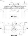
Gemäß einem Aspekt des Metrologiesystems in der vorliegenden Offenbarung umfasst das Metrologiesystem außerdem eine Steuerung, die funktionell mit dem Aktuatorsystem gekoppelt ist, wobei die Steuerung dafür ausgelegt ist, ein Teilchen von der SPM-Spitze auf die Sammelaussparung oder das Sammeldurchgangsloch des Sammlers zu übertragen, indem die SPM-Spitze gegen die erste Innenkante gezogen wird.In accordance with one aspect of the metrology system in the present disclosure, the metrology system further includes a controller operatively coupled to the actuator system, the controller configured to transmit a particle from the SPM tip to the collector recess or through hole of the collector by the SPM tip is pulled against the first inside edge.
Gemäß einem Aspekt des Metrologiesystems in der vorliegenden Offenbarung bildet die innere Fläche des Sammlers einen Durchgangsloch-Durchlass. Gemäß einem Aspekt der vorliegenden Offenbarung ist der Durchgangsloch-Durchlass ein tetraederstumpfförmiger Durchlass, ein kegelstumpfförmiger Durchlass, ein abgestumpft tetraedrischer Durchlass oder ein pyramidenstumpfförmiger Durchlass.In accordance with one aspect of the metrology system in the present disclosure, the interior surface of the header defines a through hole passage. According to one aspect of the present disclosure, the through hole passage is a truncated tetrahedral passage, a frustoconical passage, a truncated tetrahedral passage, or a truncated pyramidal passage.
Gemäß einem Aspekt des Metrologiesystems in der vorliegenden Offenbarung weist die SPM-Spitze eine Tetraederform, eine Kegelform oder eine Pyramidenform auf.According to one aspect of the metrology system in the present disclosure, the SPM tip has a tetrahedral shape, a cone shape, or a pyramid shape.
Gemäß einem Aspekt des Metrologiesystems in der vorliegenden Offenbarung ist die Sammelaussparung oder das Sammeldurchgangsloch abnehmbar an dem Metrologiesystem befestigt.According to one aspect of the metrology system in the present disclosure, the collection recess or the collection through hole is detachably attached to the metrology system.
Gemäß einem Aspekt der vorliegenden Offenbarung wird ein Teilchensammel- und Metrologiesystem bereitgestellt. Das Teilchensammel- und Metrologiesystem umfasst eine Rastersondenmikroskopie-Spitze (SPM-Spitze), eine Bühne, die dafür ausgelegt ist, ein Substrat zu halten, ein Aktuationssystem, eine Strahlungsquelle, einen Strahlungsdetektor und eine Steuerung. Das Aktuationssystem ist funktionell mit der Bühne und der SPM-Spitze gekoppelt, wobei das Aktuationssystem dafür ausgelegt ist, die SPM-Spitze relativ zu der Bühne zu bewegen. Die Strahlungsquelle befindet sich in optischer Kommunikation mit einem Messort und der Strahlungsdetektor befindet sich in optischer Kommunikation mit dem Messort. Die Steuerung ist funktionell mit dem Aktuationssystem, der Strahlungsquelle und dem Strahlungsdetektor gekoppelt. Die Steuerung ist außerdem dafür ausgelegt, die SPM-Spitze von einem Ort in der Nähe des Substrats zu dem Messort zu bewegen und ein erstes Signal von dem Strahlungsdetektor, das auf eine Antwort des Strahlungsdetektors auf eine erste Probenstrahlung von dem Messort hinweist, zu empfangen, wobei die erste Probenstrahlung durch eine erste einfallende Strahlung von der Strahlungsquelle verursacht wird.According to one aspect of the present disclosure, a particle collection and metrology system is provided. The particle collection and metrology system includes a scanning probe microscopy (SPM) tip, a stage designed to hold a substrate, an actuation system, a radiation source, a radiation detector, and a controller. The actuation system is operatively coupled to the stage and the SPM tip, the actuation system being designed to move the SPM tip relative to the stage. The radiation source is in optical communication with a measuring location and the radiation detector is in optical communication with the measuring location. The control is functionally coupled to the actuation system, the radiation source and the radiation detector. The controller is also designed to move the SPM tip from a location close to the substrate to the measurement location and to receive a first signal from the radiation detector indicative of a response of the radiation detector to a first sample radiation from the measurement location, wherein the first sample radiation is caused by a first incident radiation from the radiation source.
Gemäß einem Aspekt des Teilchensammel- und Metrologiesystems in der vorliegenden Offenbarung ist der Messort auf zumindest einem Teil der SPM-Spitze angeordnet und die Steuerung ist außerdem dafür ausgelegt, die erste Probenstrahlung zu verursachen, indem der Messort mit der ersten einfallenden Strahlung bestrahlt wird.According to one aspect of the particle collection and metrology system in the present disclosure, the measurement location is arranged on at least a part of the SPM tip and the controller is also configured to cause the first sample radiation by irradiating the measurement location with the first incident radiation.
Gemäß einem Aspekt des Teilchensammel- und Metrologiesystems in der vorliegenden Offenbarung umfasst das Teilchensammel- und Metrologiesystem außerdem einen Teilchensammler, wobei der Messort auf zumindest einem Teil des Teilchensammlers angeordnet ist. Die Steuerung ist außerdem dafür ausgelegt, die erste Probenstrahlung zu verursachen, indem der Messort mit der ersten einfallenden Strahlung bestrahlt wird.According to one aspect of the particle collection and metrology system in the present disclosure, the particle collection and metrology system further comprises a particle collector, wherein the measurement location is arranged on at least a part of the particle collector. The controller is also designed to cause the first sample radiation by irradiating the measurement location with the first incident radiation.
Gemäß einem Aspekt des Teilchensammel- und Metrologiesystems in der vorliegenden Offenbarung ist die Steuerung außerdem dafür ausgelegt, ein Teilchen von dem Substrat mit der SPM-Spitze zu dem Messort zu übertragen.According to one aspect of the particle collection and metrology system in the present disclosure, the controller is also configured to transfer a particle from the substrate with the SPM tip to the measurement location.
Gemäß einem Aspekt des Teilchensammel- und Metrologiesystems in der vorliegenden Offenbarung umfasst das Teilchensammel- und Metrologiesystem außerdem eine Stelle (im Englischen: „patch“) aus einem Material, wobei das Material eine Oberflächenenergie hat, die kleiner als eine Oberflächenenergie des Substrats ist, wobei die SPM-Spitze eine darauf vorhandene Beschichtung des Materials im Nanometermaßstab umfasst.According to one aspect of the particle collection and metrology system in the present disclosure, the particle collection and metrology system further comprises a patch of a material, the material having a surface energy that is less than a surface energy of the substrate, wherein the SPM tip includes a nanometer-scale coating of the material thereon.
Gemäß einem Aspekt des Teilchensammel- und Metrologiesystems in der vorliegenden Offenbarung ist die Steuerung außerdem dafür ausgelegt, einen Kontakt zwischen der SPM-Spitze und der Stelle zu bewirken, wodurch die SPM-Spitze mit dem Material beschichtet wird.In accordance with one aspect of the particle collection and metrology system in the present disclosure, the controller is also configured to effect contact between the SPM tip and the site, thereby coating the SPM tip with the material.
Gemäß einem Aspekt des Teilchensammel- und Metrologiesystems in der vorliegenden Offenbarung umfasst das Aktuationssystem ein Spitzenaktuationssystem, das funktionell mit der SPM-Spitze gekoppelt ist und ein Bühnenaktuationssystem, das funktionell mit der Bühne gekoppelt ist. Das Spitzenaktuationssystem ist dafür ausgelegt, die SPM-Spitze relativ zu einer Basis zu bewegen und das Bühnenaktuationssystem ist dafür ausgelegt, die Bühne relativ zu der Basis zu bewegen.In accordance with one aspect of the particle collection and metrology system in the present disclosure, the actuation system includes a tip actuation system operatively coupled to the SPM tip and a stage actuation system operatively coupled to the stage. The tip actuation system is designed to move the SPM tip relative to a base and the stage actuation system is designed to move the stage relative to the base.
Gemäß einem Aspekt des Teilchensammel- und Metrologiesystems in der vorliegenden Offenbarung ist der Teilchensammler eine Sammelaussparung oder ein Sammeldurchgangsloch. Der Teilchensammler umfasst mindestens eine erste Innenkante. Die mindestens eine erste Innenkante definiert eines von einem dreieckigen, rechteckigen, kreisförmigen, elliptischen oder ovalen Umriss. Gemäß einem Aspekt der vorliegenden Offenbarung definiert die erste Innenkante einen dreieckigen oder rechteckigen Umriss, wobei jedes Teilstück des dreieckigen oder rechteckigen Umrisses eine Länge kleiner oder gleich 10 mm aufweist. Gemäß einem Aspekt der vorliegenden Offenbarung definiert die erste Innenkante einen kreisförmigen Umriss und ist ein Durchmesser des kreisförmigen Umrisses kleiner oder gleich 10 mm.According to one aspect of the particle collection and metrology system in the present disclosure, the particle collector is a collection recess or a collection through hole. The particle collector includes at least a first inner edge. The at least one first inner edge defines one of a triangular, rectangular, circular, elliptical, or oval outline. According to one aspect of the present disclosure, the first inner edge defines a triangular or rectangular outline, each portion of the triangular or rectangular outline having a length less than or equal to 10 mm. According to one aspect of the present disclosure, the first inner edge defines a circular outline and a diameter of the circular outline is less than or equal to 10 mm.
Gemäß einem Aspekt des Teilchensammel- und Metrologiesystems in der vorliegenden Offenbarung umfasst der Teilchensammler eine erste Innenkante auf einer ersten Fläche des Sammlers, eine zweite Innenkante auf einer zweiten Fläche des Sammlers, wobei die zweite Fläche der ersten Fläche gegenüberliegt, und eine innere Fläche, die sich von der ersten Innenkante zur zweiten Innenkante erstreckt. Gemäß einem Aspekt der vorliegenden Offenbarung bildet die innere Fläche einen Durchgangsloch-Durchlass. Der Durchgangsloch-Durchlass ist ein tetraederstumpfförmiger Durchlass, ein kegelstumpfförmiger Durchlass oder ein pyramidenstumpfförmiger Durchlass.According to one aspect of the particle collection and metrology system in the present disclosure, the particle collector comprises a first inner edge on a first surface of the collector, a second inner edge on a second surface of the collector, the second surface facing the first surface, and an inner surface that extends from the first inner edge to the second inner edge. In accordance with one aspect of the present disclosure, the interior surface defines a through hole passage. The through-hole passage is a truncated tetrahedral passage, a frustoconical passage, or a truncated pyramidal passage.
Gemäß einem Aspekt des Teilchensammel- und Metrologiesystems in der vorliegenden Offenbarung weist die SPM-Spitze eine Tetraederform, eine Kegelform oder eine Pyramidenform auf.According to one aspect of the particle collection and metrology system in the present disclosure, the SPM tip has a tetrahedral shape, a cone shape, or a pyramid shape.
Gemäß einem Aspekt des Teilchensammel- und Metrologiesystems in der vorliegenden Offenbarung ist die Stelle abnehmbar an der Bühne befestigt. Gemäß einem Aspekt des Teilchensammel- und Metrologiesystems in der vorliegenden Offenbarung ist die Sammelaussparung oder das Sammeldurchgangsloch abnehmbar an der Bühne befestigt.According to one aspect of the particle collection and metrology system in the present disclosure, the site is removably attached to the stage. According to one aspect of the particle collection and metrology system in the present disclosure, the collection recess or the collection through hole is removably attached to the stage.
Als erläuterndes Beispiel für die Verwendung der Vorrichtungen und Systeme wird hierin ein Verfahren zum Bestimmen einer Zusammensetzung eines Teilchens unter Verwendung einer Rastersondenmikroskopie-Spitze (SPM-Spitze) beschrieben. Das Verfahren umfasst ein Übertragen des Teilchens auf die SPM-Spitze, eine Bestrahlung der SPM-Spitze mit einer ersten einfallenden Strahlung von einer Strahlungsquelle; ein Detektieren einer ersten Probenstrahlung, die durch die erste einfallende Strahlung verursacht wird, mit einem Strahlungsdetektor; und ein Bewirken einer Relativbewegung zwischen der SPM-Spitze und mindestens einem von der Strahlungsquelle und dem Strahlungsdetektor auf Grundlage eines ersten Signals von dem Strahlungsdetektor, das eine Antwort auf die erste Probenstrahlung ist.As an illustrative example of the use of the devices and systems, a method for determining a composition of a particle using a scanning probe microscopy (SPM) tip is described herein. The method includes transferring the particle to the SPM tip, irradiating the SPM tip with first incident radiation from a radiation source; detecting a first sample radiation caused by the first incident radiation with a radiation detector; and causing relative movement between the SPM tip and at least one of the radiation source and the radiation detector based on a first signal from the radiation detector that is a response to the first sample radiation.
Gemäß einem Aspekt des Verfahrens zum Bestimmen der Zusammensetzung des Teilchens auf der SPM-Spitze gemäß dem erläuternden Beispiel umfasst das Verfahren außerdem ein Erzeugen eines ersten Frequenzspektrums der ersten Probenstrahlung auf Grundlage des ersten Signals; ein Erzeugen eines zweiten Frequenzspektrums durch Subtrahieren eines Hintergrundfrequenzspektrums von dem ersten Frequenzspektrum; und ein Bewirken einer Relativbewegung zwischen der SPM-Spitze und mindestens einem von der Strahlungsquelle und dem Strahlungsdetektor auf Grundlage des zweiten Frequenzspektrums.According to one aspect of the method for determining the composition of the particle on the SPM tip according to the illustrative example, the method further comprises generating a first frequency spectrum of the first sample radiation based on the first signal; generating a second frequency spectrum by subtracting a background frequency spectrum from the first frequency spectrum; and causing relative movement between the SPM tip and at least one of the radiation source and the radiation detector based on the second frequency spectrum.
Gemäß einem Aspekt des Verfahrens zum Bestimmen der Zusammensetzung des Teilchens auf der SPM-Spitze gemäß dem erläuternden Beispiel umfasst das Verfahren außerdem ein Erzeugen des Hintergrundfrequenzspektrums auf Grundlage einer Antwort des Strahlungsdetektors auf eine Bestrahlung der SPM-Spitze, wenn die SPM-Spitze im Wesentlichen frei von Verunreinigungen ist.According to one aspect of the method for determining the composition of the particle on the SPM tip according to the illustrative example, the method further comprises generating the background frequency spectrum based on a response of the radiation detector to an irradiation of the SPM tip when the SPM tip is essentially free of impurities is.
Gemäß einem Aspekt des Verfahrens zum Bestimmen der Zusammensetzung des Teilchens auf der SPM-Spitze gemäß dem erläuternden Beispiel umfasst das Verfahren außerdem ein Bestrahlen der SPM-Spitze mit einer zweiten einfallenden Strahlung von der Bestrahlungsquelle; ein Detektieren einer zweiten Probenstrahlung, die von der zweiten einfallenden Strahlung verursacht wird, mit dem Strahlungsdetektor; und ein Bewirken einer Relativbewegung zwischen der SPM-Spitze und mindestens einem von der Strahlungsquelle und dem Strahlungsdetektor auf Grundlage eines zweiten Signals von dem Strahlungsdetektor, das eine Antwort auf die zweite Probenstrahlung ist.According to one aspect of the method for determining the composition of the particle on the SPM tip according to the illustrative example, the method further comprises irradiating the SPM tip with a second incident radiation from the irradiation source; detecting a second sample radiation caused by the second incident radiation with the radiation detector; and causing relative movement between the SPM tip and at least one of the radiation source and the radiation detector based on a second signal from the radiation detector that is a response to the second sample radiation.
Gemäß einem Aspekt des Verfahrens zum Bestimmen der Zusammensetzung des Teilchens auf der SPM-Spitze gemäß dem erläuternden Beispiel umfasst das Verfahren außerdem ein Bewirken einer Relativbewegung zwischen der SPM-Spitze und mindestens einem von der Strahlungsquelle und dem Strahlungsdetektor auf Grundlage einer Differenz zwischen dem zweiten Signal und dem ersten Signal.According to one aspect of the method for determining the composition of the particle on the SPM tip according to the illustrative example, the method further comprises causing relative movement between the SPM tip and at least one of the radiation source and the radiation detector based on a difference between the second signal and the first signal.
Gemäß einem Aspekt des Verfahrens zum Bestimmen der Zusammensetzung des Teilchens auf der SPM-Spitze gemäß dem erläuternden Beispiel ist die erste einfallende Strahlung von der Strahlungsquelle mindestens eines von Röntgenstrahlung, sichtbarem Licht, infrarotem Licht, ultraviolettem Licht, einem Elektronenstrahl und einem Laser. Gemäß einem Aspekt des Verfahrens zum Bestimmen der Zusammensetzung des Teilchens auf der SPM-Spitze gemäß dem erläuternden Beispiel ist die zweite einfallende Strahlung von der Strahlungsquelle mindestens eines von Röntgenstrahlung, sichtbarem Licht, infrarotem Licht, ultraviolettem Licht, einem Elektronenstrahl und einem Laser. Die zweite einfallende Strahlung ist eine andere Art von Strahlung als die erste einfallende Strahlung. In einem Aspekt wird die erste Probenstrahlung durch die Wechselwirkung der ersten einfallenden Strahlung mit der SPM-Spitze erzeugt. In einem Aspekt kann die Wechselwirkung eines oder mehrere davon umfassen, dass die erste einfallende Strahlung von der SPM-Spitze reflektiert, gebrochen oder absorbiert und reemittiert wird. In einem Aspekt wird die erste Probenstrahlung dadurch erzeugt, dass die erste einfallende Strahlung mit Fremdkörpern, die auf der SPM-Spitze angeordnet sind, wechselwirkt. In einem Aspekt kann die Wechselwirkung eines oder mehrere davon umfassen, dass die erste einfallende Strahlung von Fremdkörpern, die auf der SPM-Spitze angeordnet sind, reflektiert, gebrochen oder absorbiert und reemittiert wird.In one aspect of the method for determining the composition of the particle on the SPM tip according to the illustrative example, the first incident radiation from the radiation source is at least one of x-rays, visible light, infrared light, ultraviolet light, an electron beam, and a laser. In one aspect of the method for determining the composition of the particle on the SPM tip according to the illustrative example, the second incident radiation from the radiation source is at least one of x-rays, visible light, infrared light, ultraviolet light, an electron beam, and a laser. The second incident radiation is a different type of radiation than the first incident radiation. In one aspect, the first sample radiation is generated by the interaction of the first incident radiation with the SPM tip. In one aspect, the interaction may include one or more of the first incident radiation being reflected, refracted, or absorbed and re-emitted by the SPM tip. In one aspect, the first sample radiation is generated in that the first incident radiation interacts with foreign bodies which are arranged on the SPM tip. In one aspect, the interaction may include one or more of the fact that the first incident radiation is reflected, refracted, or absorbed and re-emitted by foreign bodies located on the SPM tip.
Gemäß einem Aspekt des Verfahrens zum Bestimmen der Zusammensetzung des Teilchens auf der SPM-Spitze gemäß dem erläuternden Beispiel umfasst das Verfahren außerdem ein Anpassen einer Intensität oder Frequenz der ersten einfallenden Strahlung von der Strahlungsquelle. In einem Aspekt umfasst das Verfahren gemäß dem erläuternden Beispiel außerdem ein Anpassen einer Intensität oder Frequenz der zweiten einfallenden Strahlung von der Strahlungsquelle.According to one aspect of the method for determining the composition of the particle on the SPM tip according to the illustrative example, the method further comprises adjusting an intensity or frequency of the first incident radiation from the radiation source. In one aspect, the method according to the illustrative example also comprises an adaptation of an intensity or frequency of the second incident radiation from the radiation source.
Als erläuterndes Beispiel für die Verwendung der Vorrichtungen und Systeme wird hierin ein Verfahren zum Bestimmen einer Zusammensetzung eines Teilchens, das von einem Substrat entfernt wurde, beschrieben. Das Verfahren umfasst ein Übertragen eines Teilchens von dem Substrat auf eine Rastersondenmikroskopie-Spitze (SPM-Spitze); ein Bestrahlen des Teilchens mit einer ersten einfallenden Strahlung von einer Strahlungsquelle; und ein Empfangen einer ersten Probenstrahlung von dem Teilchen an einem Strahlungsdetektor, wobei die erste Probenstrahlung durch die erste einfallende Strahlung verursacht wird.As an illustrative example of the use of the devices and systems, a method for determining a composition of a particle that has been removed from a substrate is described herein. The method includes transferring a particle from the substrate to a scanning probe microscopy (SPM) tip; irradiating the particle with a first incident radiation from a radiation source; and receiving a first sample radiation from the particle at a radiation detector, the first sample radiation being caused by the first incident radiation.
Gemäß einem Aspekt des Verfahrens zum Bestimmen der Zusammensetzung des von dem Substrat entfernten Teilchens gemäß dem erläuternden Beispiel wird die erste Probenstrahlung von dem Teilchen von dem Strahlungsdetektor empfangen, während das Teilchen auf der SPM-Spitze angeordnet ist.According to one aspect of the method for determining the composition of the particle removed from the substrate according to the illustrative example, the first sample radiation from the particle is received by the radiation detector while the particle is placed on the SPM tip.
Gemäß einem Aspekt des Verfahrens zum Bestimmen der Zusammensetzung des von dem Substrat entfernten Teilchens gemäß dem erläuternden Beispiel umfasst das Übertragen des Teilchens von dem Substrat auf die SPM-Spitze ein Kontaktieren der SPM-Spitze gegen das Substrat und ein Bewegen der SPM-Spitze relativ zu dem Substrat.According to one aspect of the method for determining the composition of the particle removed from the substrate according to the illustrative example, transferring the particle from the substrate to the SPM tip includes contacting the SPM tip against the substrate and moving the SPM tip relative to it the substrate.
Gemäß einem Aspekt des Verfahrens zum Bestimmen der Zusammensetzung des von dem Substrat entfernten Teilchens gemäß dem erläuternden Beispiel umfasst das Verfahren außerdem ein Übertragen des Teilchens zu einem Messort unter Verwendung der SPM-Spitze.According to one aspect of the method for determining the composition of the particle removed from the substrate according to the illustrative example, the method further comprises transmitting the particle to a measurement location using the SPM tip.
Gemäß einem Aspekt des Verfahrens zum Bestimmen der Zusammensetzung des von dem Substrat entfernten Teilchens gemäß dem erläuternden Beispiel umfasst das Verfahren außerdem ein Übertragen des Teilchens von der SPM-Spitze auf einen Teilchensammler mit einem auf dem Teilchensammler festgelegten Messort. Die erste Probenstrahlung von dem Teilchen wird von dem Strahlungsdetektor empfangen, während das Teilchen an dem Messort angeordnet ist. Die Übertragung des Teilchens von der SPM-Spitze auf den Teilchensammler umfasst ein Kontaktieren der SPM-Spitze gegen den Messort und ein Bewegen der SPM-Spitze relativ zum Messort.According to one aspect of the method for determining the composition of the particle removed from the substrate according to the illustrative example, the method further comprises transferring the particle from the SPM tip to a particle collector having a measurement location defined on the particle collector. The first sample radiation from the particle is received by the radiation detector while the particle is located at the measurement location. The transfer of the particle from the SPM tip to the particle collector includes contacting the SPM tip against the measurement location and moving the SPM tip relative to the measurement location.
Gemäß einem Aspekt des Verfahrens zum Bestimmen der Zusammensetzung des von dem Substrat entfernten Teilchens gemäß dem erläuternden Beispiel ist der Teilchensammler eine Sammelaussparung oder ein Sammeldurchgangsloch, die bzw. das mindestens eine Verunreinigungs-Sammelkante umfasst, und umfasst das Übertragen des Teilchens von der SPM-Spitze auf den Teilchensammler ein Manövrieren der SPM-Spitze, um sie gegen die Verunreinigungs-Sammelkante zu bürsten oder zu ziehen. Gemäß einem Aspekt umfasst das Manövrieren ein Bewegen der SPM-Spitze auf die mindestens eine Verunreinigungs-Sammelkante zu und dann von ihr weg. In einem Aspekt kann das Bewegen der SPM-Spitze eine kratzende und/oder wischende Bewegung umfassen. Gemäß einem Aspekt umfasst das Manövrieren ein Bewegen der SPM-Spitze nach oben an der mindestens einen Verunreinigungs-Sammelkante vorbei und umfasst das Manövrieren außerdem ein Bewegen der SPM-Spitze nach unten an der mindestens einen Verunreinigungs-Sammelkante vorbei. Gemäß einem Aspekt umfasst das Manövrieren ein Bewegen der SPM-Spitze nach oben und von einer Mitte des Teilchensammlers weg. Gemäß einem Aspekt umfasst das Manövrieren ein Bewegen des SPM nach unten und auf eine Mitte des Teilchensammlers zu. Gemäß einem Aspekt umfasst das Manövrieren ein Bewegen der SPM-Spitze auf einer parabelförmigen Bahn. Gemäß einem Aspekt umfasst das Manövrieren außerdem ein Drehen der SPM-Spitze, um eine Übertragung von Verunreinigungen, die auf einem anderen Teil der SPM-Spitze abgeladen sind, auf den Teilchensammler zu ermöglichen.According to one aspect of the method for determining the composition of the particle removed from the substrate according to the illustrative example, the particle collector is a collection recess or through hole that includes at least one contaminant collection edge and comprises transferring the particle from the SPM tip on the particle collector, maneuvering the SPM tip to brush or pull it against the debris collection edge. In one aspect, maneuvering includes moving the SPM tip toward and then away from the at least one contaminant collection edge. In one aspect, moving the SPM tip can be scratchy and / or include wiping motion. In one aspect, maneuvering includes moving the SPM tip up past the at least one contaminant collection edge, and the maneuvering further includes moving the SPM tip down past the at least one contaminant collection edge. In one aspect, maneuvering includes moving the SPM tip up and away from a center of the particle collector. In one aspect, maneuvering includes moving the SPM down and toward a center of the particle collector. In one aspect, maneuvering includes moving the SPM tip on a parabolic path. In one aspect, the maneuvering also includes rotating the SPM tip to allow contaminants dumped on a different part of the SPM tip to be transferred to the particle collector.
Gemäß einem Aspekt der vorliegenden Offenbarung umfasst ein Erzeugnis ein nichtflüchtiges maschinenlesbares Medium, auf dem Befehle codiert sind, um einen Prozessor dazu zu veranlassen, eine Zusammensetzung eines Teilchens auf einer Rastersondenmikroskopie (SPM) zu bestimmen. Die codierten Befehle des Erzeugnisses können dazu verwendet werden, um Schritte des Detektierens einer ersten Probenstrahlung mit einem Strahlungsdetektor, wobei die erste Probenstrahlung eine Antwort auf eine erste einfallende Strahlung von einer Strahlungsquelle ist; und eines Bewirkens einer Relativbewegung zwischen der SPM-Spitze und mindestens einem von der Strahlungsquelle und dem Strahlungsdetektor auf Grundlage eines ersten Signals von dem Strahlungsdetektor als Antwort auf die erste Probenstrahlung durchzuführen.In accordance with one aspect of the present disclosure, an article of manufacture includes a non-transitory machine readable medium having instructions encoded thereon to cause a processor to determine a composition of a particle on scanning probe microscopy (SPM). The encoded instructions of the article can be used to perform steps of detecting a first sample radiation with a radiation detector, the first sample radiation being a response to a first incident radiation from a radiation source; and causing relative movement between the SPM tip and at least one of the radiation source and the radiation detector based on a first signal from the radiation detector in response to the first sample radiation.
Es wurden somit gewisse Aspekte der Erfindung relativ breit kurz dargestellt, damit deren ausführliche Beschreibung hierin besser verstanden werden kann, und damit der vorliegende Beitrag zur Technik besser verstanden werden kann. Es gibt selbstverständlich zusätzliche Aspekte der Erfindung, die unten beschrieben werden, und die den Gegenstand der hier angehängten Ansprüche bilden.Thus, certain aspects of the invention have been briefly presented in a relatively broad manner in order that the detailed description thereof may be better understood, and so that the present contribution to the art may be better understood. There are, of course, additional aspects of the invention which are described below and which form the subject of the claims appended hereto.
In dieser Hinsicht muss, bevor die verschiedenen Aspekte der vorliegenden Offenbarung ausführlicher erklärt werden, verstanden werden, dass die Erfindung in ihrer Anwendung nicht auf die in der folgenden Beschreibung dargelegten oder in den Zeichnungen gezeigten Details der Konstruktion und der Anordnungen der Komponenten beschränkt ist. Die Erfindung ist zusätzlich zu den beschriebenen Ausführungsformen auch für andere geeignet, und sie ist dafür geeignet, auf verschiedene Arten ausgeübt und ausgeführt zu werden. Es muss auch verstanden werden, dass die hierin verwendete Ausdrucksweise und Terminologie sowie die Zusammenfassung zum Zweck der Beschreibung dienen und nicht als einschränkend angesehen werden sollten.In this regard, before the various aspects of the present disclosure are explained in more detail, it must be understood that the invention is not limited in its application to the details of construction and component arrangements set forth in the following description or shown in the drawings. The invention is capable of others, in addition to the described embodiments, and is capable of being practiced and carried out in various ways. It is also to be understood that the language, terminology and abstract used herein are for purposes of description and should not be viewed as limiting.
Die Fachleute werden verstehen, dass die Idee, auf der diese Offenbarung basiert, ohne Weiteres als Grundlage für die Gestaltung anderer Strukturen und Systeme für die Ausführung der verschiedenen Zwecke der vorliegenden Offenbarung verwendet werden kann.Those skilled in the art will understand that the idea on which this disclosure is based can be readily used as a basis in designing other structures and systems for carrying out the various purposes of the present disclosure.
FigurenlisteFigure list
-
1A bis 1C zeigen Querschnittsansichten eines Teils einer Fremdkörperentfernungsvorrichtung während einer Abfolge von Interaktionen mit einer Oberfläche gemäß Aspekten der vorliegenden Offenbarung. 1A to 1C Figure 10 shows cross-sectional views of a portion of a debris removal device during a sequence of interactions with a surface in accordance with aspects of the present disclosure.
-
2 zeigt eine Querschnittsansicht eines Teils einer Fremdkörperentfernungsvorrichtung gemäß Aspekten der vorliegenden Offenbarung. 2 FIG. 13 shows a cross-sectional view of a portion of a foreign object removal device in accordance with aspects of the present disclosure.
-
3 zeigt eine Querschnittsansicht eines anderen Teils der in 2 gezeigten Fremdkörperentfernu ngsvorrichtung. 3 FIG. 13 shows a cross-sectional view of another part of FIG 2 foreign body removal device shown.
-
4 zeigt eine Querschnittsansicht des in 2 gezeigten Teils der Fremdkörperentfernungsvorrichtung, wobei Teilchen in die Stelle oder das Reservoir aus dem Material mit niedriger Energie eingebettet werden. 4th FIG. 11 shows a cross-sectional view of the FIG 2 portion of the debris removal device shown, wherein particles are embedded in the site or reservoir of the low energy material.
-
5 zeigt eine Querschnittsansicht des in 4 gezeigten Teils der Fremdkörperentfernungsvorrichtung, wobei sich die Spitze nicht mehr in Kontakt mit der Stelle oder dem Reservoir aus Material mit niedriger Energie befindet. 5 FIG. 11 shows a cross-sectional view of the FIG 4th portion of the foreign body removal device shown with the tip no longer in contact with the site or reservoir of low energy material.
-
6 zeigt eine Querschnittsansicht einer Spitze mit Borsten oder Fibrillen gemäß Aspekten der vorliegenden Offenbarung. 6th Figure 12 shows a cross-sectional view of a tip having bristles or fibrils in accordance with aspects of the present disclosure.
-
7A und 7B zeigen die allgemeinen Unterschiede zwischen einer steifen Fibrille und einer einwickelnden Fibrille gemäß Aspekten der vorliegenden Offenbarung. 7A and 7B show the general differences between a rigid fibril and a wrapping fibril in accordance with aspects of the present disclosure.
-
8A bis 8C zeigen einen Prozess des Lösens und Entfernens eines Nanoteilchens von einem Zielsubstrat unter Verwendung einer einzelnen steifen Fibrille gemäß Aspekten der vorliegenden Offenbarung. 8A to 8C show a process of detaching and removing a nanoparticle from a target substrate using a single rigid fibril in accordance with aspects of the present disclosure.
-
9A bis 9C zeigen einen Prozess des Lösens und Entfernens eines Nanoteilchens von einem Zielsubstrat unter Verwendung von mehreren steifen Fibrillen gemäß Aspekten der vorliegenden Offenbarung. 9A to 9C show a process of detaching and removing a nanoparticle from a target substrate using multiple rigid fibrils in accordance with aspects of the present disclosure.
-
10A bis 10C zeigen einen Prozess des Entfernens eines Nanoteilchens von einem Zielsubstrat unter Verwendung einer einzelnen einwickelnden Fibrille gemäß Aspekten der vorliegenden Offenbarung. 10A to 10C show a process of removing a nanoparticle from a target substrate using a single wrapping fibril in accordance with aspects of the present disclosure.
-
11A bis 11D zeigen einen Prozess des Entfernens eines Nanoteilchens von einem Zielsubstrat unter Verwendung von mehreren einwickelnden Fibrillen gemäß Aspekten der vorliegenden Offenbarung. 11A to 11D show a process of removing a nanoparticle from a target substrate using multiple wrapping fibrils in accordance with aspects of the present disclosure.
-
12 zeigt eine Perspektivansicht einer Fremdkörpersammelvorrichtung gemäß Aspekten der vorliegenden Offenbarung, die mindestens eine Stelle umfasst. 12 FIG. 13 shows a perspective view of a foreign object collection device in accordance with aspects of the present disclosure including at least one location.
-
13 zeigt eine Perspektivansicht einer Fremdkörpersammelvorrichtung gemäß Aspekten der vorliegenden Offenbarung, die mindestens zwei Stellen umfasst. 13 FIG. 10 shows a perspective view of a foreign object collection device in accordance with aspects of the present disclosure including at least two locations.
-
14 zeigt eine Perspektivansicht einer Fremdkörpersammelvorrichtung gemäß Aspekten der vorliegenden Offenbarung, die eine Steuerung umfasst. 14th FIG. 13 shows a perspective view of a foreign object collection device including a controller in accordance with aspects of the present disclosure.
-
15 zeigt eine Perspektivansicht einer Fremdkörpersammelvorrichtung gemäß Aspekten der vorliegenden Offenbarung, die ein Metrologiesystem umfasst. 15th FIG. 13 shows a perspective view of a foreign object collection device including a metrology system in accordance with aspects of the present disclosure.
-
16 zeigt eine Perspektivansicht einer Fremdkörpersammelvorrichtung gemäß Aspekten der vorliegenden Offenbarung, die ein Metrologiesystem und eine Steuerung umfasst. 16 FIG. 10 is a perspective view of a foreign object collection device, including a metrology system and a controller, in accordance with aspects of the present disclosure.
-
17A und 17B zeigen eine Draufsicht bzw. eine Seitenansicht einer Fremdkörpersammelvorrichtung gemäß Aspekten der vorliegenden Offenbarung, die eine Metrologievorrichtung umfasst. 17A and 17B 10 show a top view and a side view, respectively, of a foreign object collection device, in accordance with aspects of the present disclosure, including a metrology device.
-
18A und 18B zeigen eine Draufsicht bzw. eine Seitenansicht einer Fremdkörpersammelvorrichtung gemäß Aspekten der vorliegenden Offenbarung, die eine Metrologievorrichtung und eine Steuerung umfasst. 18A and 18B 12 show a top view and a side view, respectively, of a foreign object collection device, in accordance with aspects of the present disclosure, including a metrology device and a controller.
-
19A und 19B zeigen eine Draufsicht bzw. eine Seitenansicht einer Fremdkörpersammelvorrichtung gemäß Aspekten der vorliegenden Offenbarung, die eine Metrologievorrichtung und mehrere Stellen und/oder Fremdkörpersammler umfasst. 19A and 19B 10 shows a top view and a side view, respectively, of a debris collection device, in accordance with aspects of the present disclosure, including a metrology device and multiple sites and / or debris collectors.
-
20A und 20B zeigen eine Draufsicht bzw. eine Seitenansicht einer Fremdkörpersammelvorrichtung gemäß Aspekten der vorliegenden Offenbarung, die eine Metrologievorrichtung mit einer Steuerung und mehreren Stellen und/oder Fremdkörpersammlern umfasst. 20A and 20B 10 shows a top view and a side view, respectively, of a debris collection device in accordance with aspects of the present disclosure, including a metrology device with a controller and multiple locations and / or debris collectors.
-
21A und 21B zeigen eine Draufsicht bzw. eine Seitenansicht einer Fremdkörpersammelvorrichtung gemäß Aspekten der vorliegenden Offenbarung, die einen Roboterarm umfasst. 21A and 21B 13 show a top view and a side view, respectively, of a foreign object collection device including a robotic arm, according to aspects of the present disclosure.
-
22A und 22B zeigen eine Draufsicht bzw. eine Seitenansicht der Fremdkörpersammelvorrichtung gemäß 21A und 21B, in der sich der Roboterarm in einer zweiten Position befindet. 22A and 22B show a plan view and a side view of the foreign body collecting device according to FIG 21A and 21B in which the robot arm is in a second position.
-
23A und 23B zeigen eine Draufsicht bzw. eine Seitenansicht einer Spitzenhalteanordnung gemäß Aspekten der vorliegenden Offenbarung. 23A and 23B 10 illustrate a top view and a side view, respectively, of a tip holder assembly in accordance with aspects of the present disclosure.
-
24A und 24B zeigen eine Untersicht bzw. eine Seitenansicht eines Metrologiesystems gemäß Aspekten der vorliegenden Offenbarung, das mit einer tetraederförmigen Spitze verwendbar ist. 24A and 24B 10 show a bottom view and a side view, respectively, of a metrology system in accordance with aspects of the present disclosure that is usable with a tetrahedral tip.
-
25A und 25B zeigen eine Untersicht bzw. eine Seitenansicht des Metrologiesystems der 24A und 24B, in dem Fremdkörper an der tetraederförmigen Spitze anhaften. 25A and 25B show a bottom view and a side view of the metrology system of FIG 24A and 24B , in which foreign matter adheres to the tetrahedral tip.
-
26A und 26B zeigen eine Untersicht bzw. eine Seitenansicht eines Metrologiesystems gemäß Aspekten der vorliegenden Offenbarung, das mit einer kreiskegelförmigen Spitze verwendbar ist. 26A and 26B 10 show a bottom view and a side view, respectively, of a metrology system in accordance with aspects of the present disclosure that is usable with a circular conical tip.
-
27A und 27B zeigen eine Untersicht bzw. eine Seitenansicht des Metrologiesystems der 26A und 26B, in dem Fremdkörper an der kreiskegelförmigen Spitze anhaften. 27A and 27B show a bottom view and a side view of the metrology system of FIG 26A and 26B , in which foreign matter adheres to the circular cone-shaped tip.
-
28A und 28B zeigen eine Untersicht bzw. eine Seitenansicht eines Metrologiesystem gemäß Aspekten der vorliegenden Offenbarung, das mit einer pyramidenförmigen Spitze verwendbar ist. 28A and 28B 10 show a bottom view and a side view, respectively, of a metrology system in accordance with aspects of the present disclosure that is usable with a pyramidal tip.
-
29A und 29B zeigen eine Untersicht bzw. eine Seitenansicht des Metrologiesystems der 28A und 28B, in dem Fremdkörper an der pyramidenförmigen Spitze anhaften. 29A and 29B show a bottom view and a side view of the metrology system of FIG 28A and 28B , in which foreign matter adheres to the pyramidal tip.
-
30A und 30B zeigen eine seitliche Querschnittsansicht bzw. eine Draufsicht eines Verunreinigungssammlers gemäß Aspekten der vorliegenden Offenbarung mit einer Sammelaussparung, die einen dreieckigen Grundriss hat. 30A and 30B 13 show a side cross-sectional view and a top view, respectively, of a contaminant collector in accordance with aspects of the present disclosure having a collection recess that is triangular in plan.
-
31A und 31B zeigen eine seitliche Querschnittsansicht bzw. eine Draufsicht eines Verunreinigungssammlers gemäß Aspekten der vorliegenden Offenbarung mit einer Sammelaussparung, die einen kreisförmigen Grundriss hat. 31A and 31B 13 show a side cross-sectional view and a top view, respectively, of a contaminant collector in accordance with aspects of the present disclosure having a collection recess that is circular in plan.
-
32A und 32B zeigen eine seitliche Querschnittsansicht bzw. eine Draufsicht eines Verunreinigungssammlers gemäß Aspekten der vorliegenden Offenbarung mit einer Sammelaussparung, die einen quadratischen Grundriss hat. 32A and 32B 13 show a side cross-sectional view and a top view, respectively, of a contaminant collector in accordance with aspects of the present disclosure having a collection recess that is square in plan.
-
33A bis 33C zeigen einen beispielhaften Fremdkörpersammelprozess gemäß Aspekten der vorliegenden Offenbarung, bei dem ein Verunreinigungssammler mit einer Sammelaussparung verwendet wird. 33A to 33C show an exemplary foreign object collection process in accordance with aspects of the present disclosure in which a Contamination collector is used with a collection recess.
-
34A bis 34C zeigen einen anderen beispielhaften Fremdkörpersammelprozess gemäß Aspekten der vorliegenden Offenbarung, bei dem ein Verunreinigungssammler mit einer Sammelaussparung verwendet wird. 34A to 34C 13 depict another exemplary foreign matter collection process in accordance with aspects of the present disclosure that utilizes a contaminant collector with a collection recess.
-
35A und 35B zeigen eine seitliche Querschnittsansicht bzw. eine Draufsicht eines Verunreinigungssammlers gemäß Aspekten der vorliegenden Offenbarung mit einem Sammeldurchgangsloch, das einen tetraederstumpfförmigen Durchlass definiert. 35A and 35B 13 show a side cross-sectional view and a top view, respectively, of a contaminant collector in accordance with aspects of the present disclosure having a collection through hole defining a frusto-tetrahedral passage.
-
36A und 36B zeigen eine seitliche Querschnittsansicht bzw. eine Draufsicht eines Verunreinigungssammlers gemäß Aspekten der vorliegenden Offenbarung mit einem Sammeldurchgangsloch, das einen kegelstumpfförmigen Durchlass definiert. 36A and 36B 13 show a side cross-sectional view and a top view, respectively, of a contaminant collector in accordance with aspects of the present disclosure having a collection through hole defining a frustoconical passage.
-
37A und 37B zeigen eine seitliche Querschnittsansicht bzw. eine Draufsicht eines Verunreinigungssammlers gemäß Aspekten der vorliegenden Offenbarung mit einem Sammeldurchgangsloch, das einen pyramidenstumpfförmigen Durchlass definiert. 37A and 37B 13 show a side cross-sectional view and a top view, respectively, of a contaminant collector in accordance with aspects of the present disclosure having a collection through hole defining a frusto-pyramidal passage.
-
38 zeigt eine seitliche Querschnittsansicht eines Verunreinigungssammlers mit einem Sammeldurchgangsloch und eines Metrologiesystems gemäß Aspekten der vorliegenden Offenbarung. 38 FIG. 13 shows a side cross-sectional view of a contaminant collector with a collection through hole and a metrology system in accordance with aspects of the present disclosure.
Ausführliche BeschreibungDetailed description
Die erfinderischen Aspekte werden nun mit Bezug auf die Zeichnungsfiguren beschrieben, in denen durchgängig gleiche Bezugszeichen auf gleiche Teile verweisen.The inventive aspects will now be described with reference to the drawing figures, in which like reference characters refer to like parts throughout.
Mit Bezug auf die 1A, 1B, 1C, 2, 3, 4 und 5 wird nun eine beispielhafte Vorrichtung zum Entfernen von Teilchen von einem Substrat und für ihre Übertragung auf ein Stelle beschrieben. 1A bis 1C zeigen Querschnittsansichten eines Teils einer Fremdkörperentfernungsvorrichtung 1 während einer Abfolge von Interaktionen mit einer Oberfläche gemäß Aspekten der vorliegenden Offenbarung. Eine mögliche Abfolge von Interaktionen mit einer Oberfläche, mit denen selektiv ein Teilchen 2 von einem Substrat 3 festgehalten und anschließend an einer weichen Stelle 4 abgesetzt werden könnte, ist in den Figuren gezeigt (Bewegung von links nach rechts). In 1A verunreinigt ein Teilchen 2 ein Substrat 3 mit einer (relativ) hohen Oberflächenenergie, wodurch seine Oberflächenenergie verringert wird und die Entropie des Gesamtsystems zunimmt. Als Nächstes wird in 1 B eine Spitze 5 mit einer diffusiv beweglichen Beschichtung mit niedriger Oberflächenenergie angetrieben, um das Substrat 3, das die (wiederum relativ) höhere Oberflächenenergie hat und das Teilchen 2 zu beschichten, wodurch sie voneinander abgelöst werden. Anschließend kann die Verminderung des Materials mit niedriger Oberflächenenergie die Oberflächenenergie der Spitze 5 leicht erhöht haben (näher an ihrem normalen, unbeschichteten Wert), so dass ein Energiegradient vorhanden ist, um das nun abgelöste Teilchen 2 an einer Oberfläche der Spitze 6 festzuhalten (außerdem haben Materialien wie Fluorkohlenwasserstoffe üblicherweise eine gute Kohäsion). Diese Wechselwirkungen sollten auch die Entropie des Systems erhöhen, vor allem, wenn die Spitzenoberfläche 6 sauberer als das Substrat ist. Schließlich wird in 1C das Teilchen 2 mechanisch in dem Material der weichen Stelle 4 deponiert und durch diesen mechanischen Vorgang wird auch die Spitzenoberfläche 6 wieder mit dem Material mit niedriger Oberflächenenergie beschichtet, wodurch sowohl die Energie des Systems verringert als auch seine Entropie erhöht werden sollte.With reference to the 1A , 1B , 1C , 2 , 3 , 4th and 5 An exemplary apparatus for removing particles from a substrate and transferring them to a site will now be described. 1A to 1C Figure 11 shows cross-sectional views of part of a foreign matter removal device 1 during a sequence of interactions with a surface in accordance with aspects of the present disclosure. A possible sequence of interactions with a surface that selectively use a particle 2 from a substrate 3 held and then on a soft spot 4th could be deposited, is shown in the figures (movement from left to right). In 1A contaminates a particle 2 a substrate 3 with a (relatively) high surface energy, whereby its surface energy is reduced and the entropy of the entire system increases. Next, in 1 B a peak 5 powered with a diffusively moving low surface energy coating to the substrate 3 , which has the (again relatively) higher surface energy and the particle 2 to coat, whereby they are separated from each other. Subsequently, the lower surface energy material can decrease the surface energy of the tip 5 slightly increased (closer to their normal, uncoated value) so that there is an energy gradient around the now detached particle 2 on one surface of the tip 6th (in addition, materials like fluorocarbons usually have good cohesion). These interactions should also increase the entropy of the system, especially if the tip surface 6th cleaner than the substrate. Finally, in 1C the particle 2 mechanically in the soft spot material 4th deposited and through this mechanical process also the tip surface 6th recoated with the low surface energy material, which should both decrease the energy of the system and increase its entropy.
2 zeigt eine Querschnittsansicht eines Teils einer Fremdkörperentfernungsvorrichtung 10 gemäß einer Ausführungsform der vorliegenden Offenbarung. Die Vorrichtung 10 umfasst eine Spitze 12 im Nanometermaßstab, die neben einer Stelle oder einem Reservoir 14 aus einem Material mit niedriger Oberflächenenergie angeordnet ist. Das Material mit niedriger Oberflächenenergie in dem Reservoir kann fest, flüssig, halbflüssig oder halbfest sein. 2 Fig. 13 shows a cross-sectional view of part of a foreign matter removal device 10 according to an embodiment of the present disclosure. The device 10 includes a tip 12 at the nanometer scale, next to a body or reservoir 14th is arranged from a material with low surface energy. The low surface energy material in the reservoir can be solid, liquid, semi-liquid, or semi-solid.
Auf der Spitze 12 ist eine Beschichtung 16 gebildet. Vor dem Bilden der Beschichtung 16 kann die Spitze 12 vorbeschichtet werden oder ihre Oberfläche kann in anderer Weise behandelt werden, um die Oberflächenenergie der Spitze 12 zu verändern (z. B. um die Kapillar-, Benetzungs- und/oder Oberflächenspannungseffekte zu verändern). Wenn sie geeignet ausgewählt ist, ermöglicht die Beschichtung 16, dass die Spitze 12 während eines längeren Zeitraums schärfer bleibt als eine unbeschichtete Spitze. Beispielsweise kann eine PTFE-beschichtete Diamantspitze eine längere Lebensdauer haben als eine unbeschichtete Diamantspitze.On the top 12 is a coating 16 educated. Before forming the coating 16 can the top 12 be precoated or their surface can be treated in some other way to reduce the surface energy of the tip 12 to change (e.g. to change the capillary, wetting and / or surface tension effects). When properly selected, the coating enables 16 that the top 12 remains sharper than an uncoated tip for an extended period of time. For example, a PTFE-coated diamond tip can have a longer service life than an uncoated diamond tip.
Gemäß gewissen Aspekten der vorliegenden Offenbarung kann die Beschichtung 16 das gleiche Material mit niedriger Oberflächenenergie enthalten, das auch an der Stelle oder in dem Reservoir aus dem Material 14 mit niedriger Energie vorhanden ist. Außerdem kann sich gemäß gewissen Aspekten der vorliegenden Offenbarung die Spitze 12 in direktem Kontakt mit der Stelle oder dem Reservoir aus Material 14 mit niedriger Energie befinden und die Beschichtung 16 kann auf der Oberfläche der Spitze 12 gebildet (oder ergänzt) werden, indem die Spitze 12 gegen die Stelle oder das Reservoir aus dem Material 14 mit niedriger Energie gerieben oder damit in Kontakt gebracht wird. Außerdem kann das Reiben der Spitze 12 gegen die Stelle oder das Reservoir aus dem Material mit niedriger Energie und/oder das Kratzen an der Stelle 14 die Oberflächendiffusion des Materials mit niedriger Oberflächenenergie über die Oberfläche der Spitze 12 verstärken.In accordance with certain aspects of the present disclosure, the coating can 16 contain the same low surface energy material that is present on the site or in the reservoir of the material 14th with low energy is present. Additionally, in accordance with certain aspects of the present disclosure, the tip 12 in direct contact with the site or reservoir of material 14th with low energy and the coating 16 can be on the surface of the tip 12 formed (or supplemented) by the tip 12 against the site or reservoir of the material 14th rubbed or brought into contact with low energy. Also, rubbing can the top 12 against the site or reservoir of the low energy material and / or scratching the site 14th the surface diffusion of the low surface energy material across the surface of the tip 12 amplify.
Gemäß gewissen Aspekten der vorliegenden Offenbarung können die Beschichtung 16 und die Stelle oder das Reservoir aus dem Material 14 mit niedriger Energie beide aus chlorierten und fluorierten kohlenstoffhaltigen Molekülen, wie beispielsweise Polytetrafluorethylen (PTFE) oder anderen ähnlichen Materialien, wie beispielsweise fluoriertem Ethylenpropylen (FEP), bestehen oder diese zumindest enthalten. Gemäß anderen Aspekten der vorliegenden Offenbarung kann zwischen der Oberfläche der Spitze 12 und der Beschichtung 16 aus dem Material mit niedriger Oberflächenenergie eine Zwischenschicht 15 aus einem metallischen Material, einem Oxid, einem Metalloxid oder einem anderen Material mit hoher Oberflächenenergie angeordnet sein. Einige repräsentative Beispiele für die Zwischenschicht umfassen, ohne darauf beschränkt zu sein, Cäsium (Cs), Iridium (Ir) und deren Oxide (sowie Chloride, Fluoride usw.). Diese zwei beispielhaften elementaren Metalle sind relativ weiche Materialien mit niedriger bzw. hoher Oberflächenenergie und somit repräsentieren sie die Optimierung eines Gradienten der Oberflächenenergie, der für eine gegebene Verunreinigung, ein gegebenes Substrat und eine gegebene Umgebung optimal ist. Zusätzlich oder alternativ kann die Oberfläche der Spitze 12 aufgeraut oder dotiert sein. Das Material mit hoher Oberflächenenergie oder die Behandlung der Spitze hat typischerweise die Wirkung, die Beschichtung 16 aus dem Material mit niedriger Oberflächenenergie stärker an die Spitze 12 zu binden. Da auch die Form der Spitze lokalisierte Variationen der Oberflächenenergiedichte beeinflusst (d. h., eine Schärfe im Nanobereich wird die Oberflächenenergiedichte direkt am Scheitelpunkt stark vergrößern), kann auch die Form der Spitze 12 verändert werden, um eine erhöhte selektive Haftung von Teilchen an der Spitze bereitzustellen. Auch eine Aufrauhung einer Spitzenoberfläche 13 der Spitze 12 kann wegen der Vergrößerung der Oberfläche, die sich im Kontakt mit dem Teilchen befindet und der Anzahl möglicher Bindungsstellen (dA) ebenfalls eine stärkere Anhaftung bereitstellen. Die Spitzenoberfläche 13 kann auch behandelt werden (möglicherweise durch chemische Prozesse oder Plasmaprozesse), so dass die Spitzenoberfläche 13 hochgradig instabile und chemisch aktive freie Bindungen enthält, die mit einem Teilchen oder einer dazwischen liegenden Beschichtung reagieren können, um die Anhaftung zu verstärken. Die Spitzenoberfläche 13 kann auch mit einem Material mit hohem Oberflächeninhalt wie Kohlenstoff hoher Dichte (HDC, im Englischen: „high density carbon“) oder diamantartigem Kohlenstoff (DLC, im Englischen: „diamond like carbon“) beschichtet sein, um den Oberflächeninhalt der mit einem Teilchen wechselwirkenden Spitze 12 zu erhöhen.According to certain aspects of the present disclosure, the coating 16 and the site or reservoir of the material 14th low energy both consist of or at least contain chlorinated and fluorinated carbonaceous molecules such as polytetrafluoroethylene (PTFE) or other similar materials such as fluorinated ethylene propylene (FEP). According to other aspects of the present disclosure, between the surface of the tip 12 and the coating 16 an intermediate layer of the material with low surface energy 15th made of a metallic material, an oxide, a metal oxide or some other material with high surface energy. Some representative examples of the intermediate layer include, but are not limited to, cesium (Cs), iridium (Ir) and their oxides (as well as chlorides, fluorides, etc.). These two exemplary elemental metals are relatively soft, low and high surface energy materials, respectively, and thus represent the optimization of a surface energy gradient that is optimal for a given contaminant, substrate, and environment. Additionally or alternatively, the surface of the tip 12 be roughened or spiked. The high surface energy material or tip treatment typically has the effect of coating 16 from the material with low surface energy stronger to the tip 12 to tie. Since the shape of the tip also influences localized variations in surface energy density (ie, a sharpness in the nanoscale will greatly increase the surface energy density directly at the apex), the shape of the tip can also 12 can be modified to provide increased selective adherence of particles to the tip. Also a roughening of a lace surface 13 the top 12 can also provide greater adhesion because of the increase in surface area in contact with the particle and the number of possible binding sites (dA). The top surface 13 can also be treated (possibly by chemical processes or plasma processes) so that the tip surface 13 contains highly unstable and chemically active dangling bonds that can react with a particle or an intervening coating to increase adhesion. The top surface 13 can also be coated with a material with a high surface area such as high density carbon (HDC) or diamond-like carbon (DLC) to reduce the surface area of the particles interacting with top 12 to increase.
Gemäß bestimmten Aspekten der vorliegenden Offenbarung wird eine Vorbehandlung mit hoher Oberflächenenergie ohne eine Beschichtung 16 mit niedriger Oberflächenenergie verwendet. In solchen Aspekten können die unten diskutierten Teilchen 20 unter Verwendung von ähnlichen Verfahren wie den hierin diskutierten in einige andere weiche Ziele (z. B. Au, AI) eingebettet werden, oder die Spitze 12 kann ein Verbrauchsmaterial sein. Es können auch andere physikalische Parameter und/oder Umgebungsparameter verändert werden (z. B. Temperatur, Druck, Chemie, Feuchtigkeit), um die Behandlung der Spitze und/oder das Aufnehmen/Ablegen von Teilchen zu verbessern, was vom Fachmann angesichts der vorliegenden Offenbarung verstanden werden wird.In accordance with certain aspects of the present disclosure, a high surface energy pretreatment is provided without a coating 16 used with low surface energy. In such aspects, the particles discussed below 20th embedded in some other soft target (e.g. Au, Al), or the tip, using procedures similar to those discussed herein 12 can be a consumable. Other physical and / or environmental parameters can also be changed (e.g., temperature, pressure, chemistry, humidity) to improve tip handling and / or particle pick-up / deposition, which will be appreciated by those skilled in the art in light of the present disclosure will be understood.
Gemäß gewissen Aspekten der vorliegenden Offenbarung sind alle der in 2 und 3 gezeigten Komponenten in einem AFM enthalten. In einigen solchen Ausgestaltungen ist die Stelle oder das Reservoir aus dem Material 14 mit niedriger Energie im Wesentlichen flach und an einer Bühne befestigt, die das Substrat 18 hält. Außerdem ist gemäß gewissen Aspekten der vorliegenden Offenbarung die Stelle oder das Reservoir aus dem Material 14 mit niedriger Energie von der Bühne entfernbar und kann leicht ersetzt werden oder leicht wiederauffüllbar sein. Beispielsweise kann die Stelle oder das Reservoir aus dem Material 14 mit niedriger Energie an dem AFM mit einer leicht lösbaren Klemmvorrichtung oder magnetischen Halterung (nicht gezeigt) befestigt sein.In accordance with certain aspects of the present disclosure, all of the in 2 and 3 components shown contained in an AFM. In some such configurations, the site or reservoir is made of the material 14th low energy essentially flat and attached to a stage holding the substrate 18th holds. Additionally, in accordance with certain aspects of the present disclosure, the site or reservoir is made of the material 14th Removable from the stage with low energy and can be easily replaced or easily refilled. For example, the site or the reservoir can be made from the material 14th low energy attached to the AFM with an easily releasable clamp or magnetic bracket (not shown).
3 zeigt eine Querschnittsansicht eines anderen Teils der in 2 gezeigten Fremdkörperentfernungsvorrichtung 10. In 3 ist ein Substrat 18 gezeigt, das typischerweise neben der Stelle oder dem Reservoir aus dem Material 14 mit niedriger Energie, das in 2 gezeigt ist, angeordnet ist. Außerdem sind in 3 mehrere Teilchen 20 gezeigt, die in einem Graben 22 anwesend sein können, der auf der Oberfläche des Substrats 18 gebildet ist. Die Teilchen 20 haften typischerweise aufgrund von kurzreichweitigen Van-der-Waals-Kräften an den Oberflächen des Grabens 22. In 3 kann die Spitze 12 bewegt und zu dem Substrat 18 benachbart positioniert werden, um die Teilchen 20 physikalisch an die Spitze 12 zu binden. Um den Boden des Grabens 22 zu erreichen, kann die Spitze 12, wie in den 2 und 3 gezeigt, eine Spitze mit einem hohen Aspektverhältnis sein. Obwohl in 3 ein Graben 22 gezeigt ist, können die Teilchen 20 auch an anderen zu reinigenden Strukturen anhaften oder vorhanden sein. 3 FIG. 13 shows a cross-sectional view of another part of FIG 2 foreign matter removal device shown 10 . In 3 is a substrate 18th shown, typically next to the site or reservoir from the material 14th low energy that is in 2 is shown, is arranged. In addition, in 3 several particles 20th shown working in a trench 22nd may be present on the surface of the substrate 18th is formed. The particles 20th typically adhere to the surfaces of the trench due to short-range Van der Waals forces 22nd . In 3 can the top 12 moved and to the substrate 18th positioned adjacent to the particles 20th physically to the top 12 to tie. Around the bottom of the trench 22nd can reach the top 12 as in the 2 and 3 shown to be a tip with a high aspect ratio. Although in 3 a ditch 22nd shown, the particles can 20th also adhere to or be present on other structures to be cleaned.
4 zeigt eine Querschnittsansicht des in 2 gezeigten Teils der Fremdkörperentfernungsvorrichtung 10, wobei die Teilchen 20 von der Spitze übertragen und in die Stelle oder das Reservoir aus dem Material 14 mit niedriger Energie eingebettet werden können, indem die Spitze in oder gegen eine Oberfläche der Stelle oder des Reservoirs aus dem Material 14 mit niedriger Energie ausgefahren wird. Anschließend kann, wie in der Querschnittsansicht der 5 gezeigt, die Spitze 12 zurückgezogen werden, so dass sich die Spitze 12 nicht mehr in Kontakt mit der Stelle oder dem Reservoir aus dem Material 14 mit niedriger Energie befindet. Wenn die Spitze 12 von der Stelle oder dem Reservoir aus dem Materials 14 mit niedriger Energie zurückgefahren oder zurückgezogen wird, verbleiben die Teilchen 20, die zuvor auf der Spitze 12 waren, an der Stelle oder dem Reservoir aus dem Material 14 mit niedriger Energie. 4th FIG. 11 shows a cross-sectional view of the FIG 2 shown part of the foreign matter removal device 10 , where the particles 20th transferred from the tip and into the site or reservoir of the material 14th Low energy can be embedded by placing the tip in or against a surface of the site or reservoir of the material 14th is extended with low energy. Then, as in the cross-sectional view of the 5 shown the top 12 be withdrawn so that the tip 12 no longer in contact with the site or the reservoir of the material 14th with low energy. When the top 12 from the site or reservoir from the material 14th is retracted or withdrawn with low energy, the particles remain 20th that previously on the top 12 were, at the point or the reservoir from the material 14th with low energy.
Gemäß gewissen Aspekten der vorliegenden Offenbarung kann die in den 2-5 gezeigte Vorrichtung 10 verwendet werden, um ein Verfahren zum Entfernen von Fremdkörpern zu implementieren. Es sollte erwähnt werden, dass gewisse Aspekte der vorliegenden Offenbarung in Verbindung mit anderen Prozessen zur Reinigung von Teilchen verwendet werden können, entweder vor oder nach den hierin diskutierten Verfahren. Außerdem sollte erwähnt werden, dass die Begriffe Teilchen, Fremdkörper oder Verunreinigung austauschbar verwendet werden können, um etwas beliebiges Fremdes auf der Substratoberfläche zu beschreiben. Es sollte auch erwähnt werden, dass, obwohl nur eine Spitze 12 in den Figuren diskutiert und dargestellt wird, mehrere Spitzen gleichzeitig verwendet werden können, um gleichzeitig Teilchen von mehreren Strukturen zu entfernen. Außerdem könnten in den hierin diskutierten Verfahren mehrere Spitzen parallel und gleichzeitig verwendet werden.In accordance with certain aspects of the present disclosure, the 2-5 shown device 10 can be used to implement a foreign object removal method. It should be noted that certain aspects of the present disclosure can be used in conjunction with other processes for cleaning particles, either before or after the methods discussed herein. It should also be noted that the terms particulate, foreign body, or impurity can be used interchangeably to describe anything foreign on the substrate surface. It should also be mentioned that although only a tip 12 As discussed and illustrated in the figures, multiple tips can be used simultaneously to simultaneously remove particles from multiple structures. Additionally, multiple tips could be used in parallel and simultaneously in the methods discussed herein.
Das oben erwähnte Fremdkörperverfahren kann ein Positionieren der Spitze 12 neben einem oder mehreren der Teilchen 20 (d. h. der Fremdkörperstücke), die in 3 als auf dem Substrat 18 befindlich gezeigt sind, umfassen. Das Verfahren kann außerdem ein physikalisches Festhalten (im Gegensatz zu einem elektrostatischen Festhalten) der Teilchen 20 auf der Spitze 12 umfassen, wie ebenfalls in 3 gezeigt, sowie einige mögliche sich wiederholende Bewegungen der Spitze 12, wenn diese sich in Kontakt mit dem oder den Teilchen 20 und den diese umgebenden Oberflächen befindet. Nach dem physikalischen Festhalten der Teilchen 20 an der Spitze 12 kann das Verfahren ein Entfernen der Teilchen 20 von dem Substrat 18 durch Bewegen und/oder Zurückziehen der Spitze 12 von dem Substrat 18 weg und ein Bewegen der Spitze 12 mit den Teilchen 20 zu der Stelle oder dem Reservoir aus dem Material 14 mit niedriger Energie umfassen, wie in 4 gezeigt.The foreign matter method mentioned above may include tip positioning 12 next to one or more of the particles 20th (i.e. the foreign body pieces) that are in 3 than on the substrate 18th located include. The method can also physically hold (as opposed to electrostatically hold) the particles 20th on the top 12 as also in 3 shown, as well as some possible repetitive tip movements 12 when this is in contact with the particle or particles 20th and the surfaces surrounding them. After the physical retention of the particles 20th at the top 12 the process can involve removing the particles 20th from the substrate 18th by moving and / or retracting the tip 12 from the substrate 18th away and moving the top 12 with the particles 20th to the site or reservoir of the material 14th with low energy, as in 4th shown.
Beispielsweise kann das Verfahren das Bilden der Beschichtung 16 auf zumindest einem Teil der Spitze 12 umfassen. In gewissen Aspekten der vorliegenden Offenbarung kann die Beschichtung 16 ein Beschichtungsmaterial umfassen, das eine Oberflächenenergie hat, die kleiner als eine Oberflächenenergie des Substrats 18 ist. Zusätzlich oder alternativ kann die Beschichtung 16 ein Beschichtungsmaterial umfassen, das einen Oberflächeninhalt hat, der größer als der Oberflächeninhalt des Teilchens 20 ist, das sich in Kontakt mit dem Substrat 18 befindet.For example, the method can include forming the coating 16 on at least part of the top 12 include. In certain aspects of the present disclosure, the coating can 16 comprise a coating material having a surface energy that is less than a surface energy of the substrate 18th is. Additionally or alternatively, the coating can 16 comprise a coating material having a surface area greater than the surface area of the particle 20th is that is in contact with the substrate 18th is located.
Zusätzlich zu dem Obigen können manche Aspekte des Verfahrens außerdem ein Bewegen der Spitze 12 zumindest zu einem zweiten Ort des Substrats umfassen, so dass sich die Spitze 12 neben anderen Stücken von Teilchen oder Fremdkörpern (nicht gezeigt) befindet, so dass die anderen Stücke von Teilchen oder Fremdkörpern physikalisch an der Spitze 12 festgehalten werden. Die anderen Stücke von Teilchen Fremdkörpern können dann von dem Substrat 18 entfernt werden, indem die Spitze 12 auf eine Weise, die zu der in 4 gezeigten analog ist, von dem Substrat 18 wegbewegt wird.In addition to the above, some aspects of the method may also include moving the tip 12 at least to include a second location of the substrate so that the tip 12 located next to other pieces of particles or foreign objects (not shown) so that the other pieces of particles or foreign objects are physically on top 12 be held. The other pieces of particles can then debris from the substrate 18th removed by the tip 12 in a way that is consistent with the in 4th is analogous to that shown, from the substrate 18th is moved away.
Sobald Fremdkörper (z. B. die oben diskutierten Teilchen 20) von dem Substrat 18 entfernt wurden, können manche Beispiele von Verfahren einen Schritt des Abladens des Fremdkörperstücks in einem Stück aus Material, das von dem Substrat entfernt platziert ist (z. B. der oben diskutierten Stelle oder dem Reservoir aus dem Material 14 mit niedriger Energie) umfassen.As soon as foreign bodies (e.g. the particles discussed above 20th ) from the substrate 18th removed, some examples of methods may include a step of dumping the debris into a piece of material placed remote from the substrate (e.g., the location discussed above or the reservoir of the material 14th with low energy).
Da die Spitze 12 wiederholt verwendet werden kann, um große Menge von Fremdkörpern zu entfernen, kann das Verfahren beispielsweise ein Ergänzen der Beschichtung 16 durch Stechen der Spitze 12 in die Stelle oder das Reservoir aus dem Material 14 mit niedriger Energie umfassen. Das Material mit niedriger Oberflächenenergie aus der Stelle oder dem Reservoir aus dem Material mit niedriger Energie kann alle Löcher oder Lücken, die sich möglicherweise im Laufe der Zeit in der Beschichtung 16 der Spitze 12 gebildet haben, beschichten. Diese Ergänzung kann eines oder mehrere von einem seitlichen Bewegen der Spitze 12 in der Stelle oder dem Reservoir aus dem Material 14 mit niedriger Energie nach dem Einstechen der Spitze 12 in die Stelle oder das Reservoir aus dem Material 14 mit niedriger Energie, ein Reiben einer Oberfläche der Spitze 12, oder ein Ändern eines physikalischen Parameters (z. B. der Temperatur) der Spitze 12 und/oder der Stelle oder des Reservoirs aus dem Material 14 mit niedriger Energie beinhalten.Because the top 12 can be used repeatedly to remove large amounts of foreign matter, the method can, for example, a replenishment of the coating 16 by pricking the tip 12 into the site or reservoir of the material 14th include low energy. The low surface energy material from the site or reservoir made from the low energy material can contain any holes or gaps that may appear in the coating over time 16 the top 12 have formed coat. This addition can be one or more of a sideways movement of the tip 12 in the site or reservoir of the material 14th with low energy after piercing the tip 12 into the site or reservoir of the material 14th low energy, rubbing a surface of the tip 12 , or changing a physical parameter (e.g. temperature) of the tip 12 and / or the site or reservoir of the material 14th contain low energy.
Es sollte erwähnt werden, dass gewisse Beispiele von Verfahren ein Aussetzen eines kleinen Gebiets um einen Defekt oder ein Teilchen an ein Material mit niedriger Oberflächenenergie, das vor einer Reparatur durchgeführt wird, umfassen können, um die Wahrscheinlichkeit, dass sich das entfernte Material nach Abschluss der Reparatur verklumpt und wieder stark an dem Substrat haftet, zu verringern. Beispielsweise können gemäß gewissen Aspekten der vorliegenden Offenbarung ein Defekt/Teilchen und ein ungefähr 1-2 Mikrometer großes Gebiet um den Defekt herum mit PTFE oder FEP vorbeschichtet werden. In solchen Fällen kann eine Spitze 12, die mit einem Material mit niedriger Oberflächenenergie beschichtet ist oder daraus aufgebaut ist (z. B. eine Spitze aus PTFE oder FEP) verwendet werden, um einem Reparaturgebiet eine sehr großzügige Menge des Materials mit niedriger Oberflächenenergie zuzuführen, auch wenn andere Reparaturwerkzeuge (Laser, Elektronenstrahl) verwendet werden. Zusätzlich zu der Beschichtung 16 auf der Spitze 12 kann ein Teil der Spitze 12 oder die gesamte Spitze 12 ein Material mit niedriger Energie wie beispielsweise, ohne jedoch darauf beschränkt zu sein, chlorierte und fluorierte kohlenstoffhaltige Moleküle umfassen. Beispiele solcher Materialien können PTFE oder FEP umfassen. Zusätzlich oder alternativ können andere Materialien wie beispielsweise Metalle und ihre Verbindungen verwendet werden. Einige repräsentative Beispiele umfassen Cs, Ir und deren Oxide (sowie Chloride, Fluoride usw.). Diese beiden beispielhaften elementaren Metalle sind relativ weiche Metalle mit niedriger bzw. hoher Oberflächenenergie, und somit repräsentieren sie die Optimierung eines Gradienten der Oberflächenenergie, der für eine gegebene Verunreinigung, ein gegebenes Substrat und eine gegebene Umgebung optimal ist. Zusätzlich oder alternativ können andere Verbindungen auf Kohlenstoffbasis verwendet werden. Einige repräsentative Beispiele umfassen HDC oder DLC.It should be noted that certain examples of methods may include exposing a small area around a defect or particle to a low surface energy material prior to a repair to reduce the likelihood that the removed material will be removed after completion of the repair Repair clumps and re-adheres strongly to the substrate, diminishing. For example, in accordance with certain aspects of the present disclosure, a defect / particle and an area approximately 1-2 micrometers around the defect can be precoated with PTFE or FEP. In such cases it can be a tip 12 coated or made up of a low surface energy material (e.g. a tip made of PTFE or FEP) can be used to deliver a very generous amount of the low surface energy material to a repair area, even if other repair tools (laser, Electron beam) can be used. In addition to the coating 16 on the top 12 can be part of the top 12 or the entire top 12 a low energy material such as, but not limited to, chlorinated and fluorinated carbonaceous molecules. Examples of such materials can include PTFE or FEP. Additionally or alternatively, other materials such as metals and their compounds can be used. Some representative examples include Cs, Ir and their oxides (as well as chlorides, fluorides, etc.). These two exemplary elemental metals are relatively soft, low and high surface energy metals, respectively, and thus represent optimizing a surface energy gradient that is optimal for a given contaminant, substrate and environment. Additionally or alternatively, other carbon-based compounds can be used. Some representative examples include HDC or DLC.
Das Verfahren kann beispielsweise ein Verwenden der Stelle oder des Reservoirs aus dem Material 14 mit niedriger Energie, um die Teilchen von einem Scheitelpunkt der Spitze 12 weg und auf einen AFM-Cantileverarm (nicht dargestellt), der die Spitze 12 oberhalb des Scheitelpunkts hält, zu zu schieben, umfassen. Ein solches Hochschieben der Teilchen 20 kann Platz in der Nähe des Scheitelpunkts der Spitze 12 freimachen, damit mehr Teilchen 20 physikalisch festgehalten werden können.The method can, for example, use the site or the reservoir from the material 14th low energy to the particle from an apex of the apex 12 away and onto an AFM cantilever arm (not shown) that spans the tip 12 above the apex holds, to push, embrace. Such a pushing up of the particles 20th can place near the apex of the top 12 free up so more particles 20th can be physically recorded.
Gemäß gewissen Aspekten der vorliegenden Offenbarung wird die Spitze 12 verwendet, um von Strukturen mit hohem Aspektverhältnis wie beispielsweise dem Graben 22 des Substrats 18 Fremdkörper aus der Nanobearbeitung zu entfernen, indem abwechselnd die Spitze 12 in eine Palette aus weichem Material, die an der Stelle oder dem Reservoir aus Material 14 mit niedriger Energie vorhanden sein kann, eingetaucht, eingeführt und/oder eingerückt wird. In ausgewählten Aspekten kann das weiche Material der Stelle oder des Reservoirs aus dem Material 14 mit niedriger Energie eine teigartige oder plastische Konsistenz haben. Dieses weiche Material kann im Allgemeinen eine stärkere Haftung an dem Material der Spitze 12 und/oder der Fremdkörper (z. B. der Teilchen 20) haben, als an sich selbst. Das weiche Material kann auch so ausgewählt sein, dass es polare Eigenschaften hat, um die Fremdkörperteilchen 20 aus der Nanobearbeitung elektrostatisch zu der Spitze 12 zu ziehen. Beispielsweise kann die Stelle oder das Reservoir aus dem Material 14 mit niedriger Energie ein bewegliches Tensid umfassen.In accordance with certain aspects of the present disclosure, the tip 12 used to of high aspect ratio structures such as the trench 22nd of the substrate 18th Remove foreign bodies from the nano-machining by alternating the tip 12 in a pallet made of soft material that is in place or the reservoir made of material 14th low energy, immersed, inserted and / or indented. In selected aspects, the soft material of the site or reservoir can be made from the material 14th have a dough-like or plastic consistency with low energy. This soft material can generally have a stronger adhesion to the material of the tip 12 and / or the foreign body (e.g. the particle 20th ) than on itself. The soft material can also be selected so that it has polar properties to the foreign body particles 20th from nano machining electrostatically to the tip 12 to pull. For example, the site or the reservoir can be made from the material 14th low energy include a mobile surfactant.
Zusätzlich zu dem Obigen kann gemäß gewissen Aspekten der vorliegenden Offenbarung die Spitze 12 eine oder mehrere dielektrische Oberflächen (d. h. elektrisch isolierte Oberflächen) umfassen. Diese Oberflächen können unter bestimmten Umweltbedingungen (z. B. geringe Feuchtigkeit) an einer ähnlich dielektrischen Oberfläche gerieben werden, um durch eine elektrostatische Aufladung der Oberfläche das Aufsammeln von Teilchen zu erleichtern. Auch kann gemäß gewissen Aspekten der vorliegenden Offenbarung die Beschichtung 16 Teilchen durch irgendeinen anderen kurzreichweitigen Mechanismus anziehen, der Wasserstoffbrückenbindungen, eine chemische Reaktion, eine erhöhte Oberflächendiffusion umfassen kann, aber nicht darauf beschränkt ist.In addition to the above, in accordance with certain aspects of the present disclosure, the tip 12 comprise one or more dielectric surfaces (ie, electrically isolated surfaces). Under certain environmental conditions (e.g. low humidity), these surfaces can be rubbed against a similar dielectric surface in order to facilitate the collection of particles by means of an electrostatic charge on the surface. In accordance with certain aspects of the present disclosure, the coating can also 16 Attracting particles by any other short range mechanism which may include, but is not limited to, hydrogen bonds, chemical reaction, increased surface diffusion.
Mit Bezug auf die 6-11 werden nun beispielhafte Aspekte der Spitze zum Entfernen von Fremdkörpern beschrieben. Jede Spitze, die stark und steif genug ist, um in das weiche Palettenmaterial der Stelle oder des Reservoirs aus dem Material 14 mit niedriger Energie einzudringen (d. h. einzurücken) kann verwendet werden. Somit liegen Spitzengeometrien mit sehr hohem Aspektverhältnis (größer als 1:1) im Bereich der vorliegenden Offenbarung. Wenn die Spitze nur steif genug ist, um in das weiche (möglicherweise klebrige) Material einzudringen, werden im Allgemeinen Spitzen mit hohem Aspektverhältnis, die stark und flexibel sind, gegenüber Spitzen, die schwächer und/oder weniger flexibel sind, bevorzugt. Somit kann gemäß gewissen Aspekten der vorliegenden Offenbarung die Spitze an den Seiten und Ecken des reparierten Grabens 22 des Substrats 18 gerieben werden, ohne den Graben 22 oder das Substrat 18 zu beschädigen oder zu verändern. Eine grobe Analogie zu diesem Vorgang im Makrobereich ist eine steife Borste, die in einem tiefen inneren Durchmesser bewegt wird. Es sollte auch erwähnt werden, dass gemäß gewissen Aspekten der vorliegenden Offenbarung die Spitze 12 mehrere unnachgiebige oder steife Nanofibrillen-Borsten umfassen kann, was unten genauer beschrieben wird. In einem Aspekt kann sich, wie in 6 gezeigt, jede Borste der mehreren unnachgiebigen oder steifen Nanofibrillen-Borsten 30 linear von der Spitze 12 weg erstrecken. In einem Aspekt können die mehreren unnachgiebigen oder steifen Nanofibrillen-Borsten 30 mit Kohlenstoff-Nanoröhrchen, Metallwhiskern usw. gebildet werden. Die Spitze 12 kann zusätzlich oder alternativ mehrere flexible oder einwickelnde Nanofibrillen umfassen, was unten genauer beschrieben wird. Die mehreren flexiblen oder einwickelnden Nanofibrillen können beispielsweise unter Verwendung von Polymermaterialien auf der Spitze 12 gebildet werden. Andere Materialien und Strukturen werden selbstverständlich in Betracht gezogen.With reference to the 6-11 Exemplary aspects of the debris removal tip will now be described. Any tip that is strong and stiff enough to slide into the soft pallet material of the body or reservoir of the material 14th low energy penetration (ie, indenting) can be used. Thus, tip geometries with a very high aspect ratio (greater than 1: 1) are within the scope of the present disclosure. Generally, if the tip is stiff enough to penetrate the soft (possibly sticky) material, high aspect ratio tips that are strong and flexible are preferred over tips that are weaker and / or less flexible. Thus, in accordance with certain aspects of the present disclosure, the tip can be at the sides and corners of the repaired trench 22nd of the substrate 18th be rubbed without digging 22nd or the substrate 18th to damage or alter. A rough analogy to this process in the macro range is a stiff bristle that is moved in a deep inner diameter. It should also be noted that in accordance with certain aspects of the present disclosure, the tip 12 may comprise a plurality of rigid or rigid nanofibril bristles, which is described in more detail below. In one aspect, as in 6th shown each bristle of the multiple rigid or rigid nanofibril bristles 30th linear from the top 12 extend away. In one aspect, the plurality of rigid or rigid nanofibril bristles can be 30th formed with carbon nanotubes, metal whiskers, etc. The summit 12 may additionally or alternatively comprise multiple flexible or wrapping nanofibrils, which is described in more detail below. The multiple flexible or wrapping Nanofibrils, for example, can be made using polymer materials on the tip 12 are formed. Other materials and structures are of course contemplated.
Gemäß gewissen Aspekten der vorliegenden Offenbarung kann die Detektion, ob ein oder mehrere Teilchen aufgesammelt wurden, unter Verwendung einer berührungslosen AFM-Abtastung des Gebiets von Interesse (ROI, im Englischen: „region of interest“) zum Detektieren von Teilchen durchgeführt werden. Die Spitze 12 kann dann von dem Substrat 18 zurückgezogen werden, ohne dass bis nach der Behandlung des Ziels eine erneute Abtastung durchgeführt wird. Die gesamte von der Spitze 12 aufgesammelte Masse des Fremdkörpermaterials kann jedoch auch durch relative Verschiebungen in der Resonanzfrequenz der Spitze überwacht werden. Zusätzlich können für die gleiche Funktion andere Dynamiken verwendet werden.In accordance with certain aspects of the present disclosure, the detection of whether one or more particles have been collected may be performed using a non-contact AFM region of interest (ROI) scan to detect particles. The summit 12 can then from the substrate 18th can be withdrawn without resampling until after the target has been treated. The entire from the top 12 However, the accumulated mass of the foreign body material can also be monitored by relative shifts in the resonance frequency of the tip. In addition, other dynamics can be used for the same function.
Anstatt sie, wie oben diskutiert und in 5 gezeigt, zum Entfernen von Teilchen 20 in ein weiches Material einzurücken, kann die Spitze 12 auch gerichtet in die Stelle oder das Reservoir aus dem Material 14 mit niedriger Energie eingebracht werden, um die Teilchen 20 zu entfernen. Wenn also die Spitze unabsichtlich ein Teilchen 20 aufsammelt, kann das Teilchen 20 durch eine weitere Reparatur entfernt werden. Insbesondere kann, wenn zum Abladen der Teilchen 20 durch gerichtetes Einbringen ein anderes Material verwendet wird, ein weiches Material wie beispielsweise eine Goldfolie verwendet werden.Instead of using them as discussed above and in 5 shown for removing particles 20th indenting in a soft material, the tip can 12 also directed into the site or reservoir of the material 14th with low energy introduced to the particles 20th to remove. So if the tip is accidentally a particle 20th collects, the particle can 20th removed by another repair. In particular, when to dump the particles 20th another material is used by directed introduction, a soft material such as gold foil can be used.
Zusätzlich zu dem Obigen kann ein durch ultraviolettes Licht (UV-Licht) härtbares Material oder in ähnlicher Weise irgendein anderes Material, das für eine nicht reversible chemische Reaktion empfänglich ist, verwendet werden, um die Spitze 12 zu beschichten und die Beschichtung 16 zu bilden. Vor der UV-Härtung sammelt das Material Teilchen 20 von dem Substrat 18 auf. Sobald die Spitze 12 von dem Substrat 18 entfernt wurde, kann die Spitze 12 einer UV-Quelle ausgesetzt werden, wodurch die Eigenschaften des Materials verändert würden, damit die Teilchen 20 weniger an der Spitze 12 anhaften und stärker an dem Material an der Stelle oder in dem Reservoir aus dem Material 14 mit niedriger Energie haften, wo die Teilchen 20 anschließend von der Spitze 12 entfernt und an der Stelle oder in dem Reservoir aus dem Material 14 mit niedriger Energie abgeladen werden können. Andere nicht reversible Prozesse, mit denen die Selektivität des Aufsammelns und Entfernens von Teilchen weiter verbessert oder ermöglicht wird, werden selbstverständlich in Betracht gezogen.In addition to the above, an ultraviolet (UV) light curable material, or similarly any other material susceptible to a non-reversible chemical reaction, can be used to form the tip 12 to coat and the coating 16 to build. The material collects particles before UV curing 20th from the substrate 18th on. Once the top 12 from the substrate 18th removed, the tip can 12 exposed to a UV source, which would change the properties of the material, so the particles 20th less at the top 12 adhere and more strongly to the material at the site or in the reservoir of the material 14th with low energy stick where the particles 20th then from the top 12 removed and in place or in the reservoir from the material 14th can be discharged with low energy. Other non-reversible processes which further improve or enable the selectivity of the collection and removal of particles are of course envisaged.
Gewisse Aspekte der vorliegenden Offenbarung stellen eine Vielfalt von Vorteilen bereit. Beispielsweise ermöglichen gewisse Aspekte der vorliegenden Offenbarung das aktive Entfernen von Fremdkörpern aus Grabenstrukturen mit hohem Aspektverhältnis unter Verwendung von AFM-Spitzengeometrien mit sehr hohem Aspektverhältnis (größer als 1:1). Außerdem können gewisse Aspekte der vorliegenden Offenbarung relativ leicht durch Anbringen einer Palette mit einem Material, das eine niedrige Oberflächenenergie hat oder ein weiches Material ist, an einem AFM, in Kombination mit der Verwendung einer Spitze mit sehr hohem Aspektverhältnis und einer Durchführung relativ geringer Anpassungen an den derzeit von AFM-Bedienern verwendeten Software-Reparatursequenzen implementiert werden. Außerdem kann gemäß gewissen Aspekten der vorliegenden Offenbarung ein neues Nanobearbeitungs-Werkzeug implementiert werden, das (wie eine Nano-Pinzette) dazu verwendet werden könnte, selektiv Teilchen von der Oberfläche einer Maske, die mit keinem anderen Verfahren gereinigt werden könnte, zu entfernen. Dies kann mit einer traditionelleren Reparatur kombiniert werden, bei der die Fremdkörper zuerst mit einer unbeschichteten Spitze von der Oberfläche abgelöst und dann mit einer beschichteten Spitze aufgesammelt würden.Certain aspects of the present disclosure provide a variety of advantages. For example, certain aspects of the present disclosure enable the active removal of debris from high aspect ratio trench structures using very high aspect ratio AFM tip geometries (greater than 1: 1). In addition, certain aspects of the present disclosure can be relatively easily applied by attaching a pallet of a material that has a low surface energy or is a soft material to an AFM, in combination with the use of a very high aspect ratio tip and making relatively minor adjustments the software repair sequences currently used by AFM operators. Additionally, in accordance with certain aspects of the present disclosure, a new nano-machining tool can be implemented that could be used (such as nano-tweezers) to selectively remove particles from the surface of a mask that could not be cleaned by any other method. This can be combined with a more traditional repair, where the debris would first be peeled off the surface with an uncoated tip and then picked up with a coated tip.
Allgemein sollte erwähnt werden, dass, obwohl in den oben diskutierten Verfahren zur lokalen Reinigung ein Material mit niedriger Oberflächenenergie verwendet wird, auch andere mögliche Varianten im Bereich der vorliegenden Offenbarung liegen. Typischerweise wird in diesen Varianten ein Gradient der Oberflächenenergie (d. h. ein Gradient der Gibb'schen freien Energie) erzeugt, der das Teilchen 20 zu der Spitze 12 zieht und danach durch irgendeine andere Behandlung umgekehrt werden kann, um die Teilchen 20 von der Spitze 12 zu lösen.In general, it should be mentioned that although a material with low surface energy is used in the local cleaning methods discussed above, other possible variants are also within the scope of the present disclosure. Typically, in these variants, a surface energy gradient (ie a gradient of Gibb's free energy) is generated, which the particle 20th to the top 12 draws and then by some other treatment can be reversed to the particles 20th from the top 12 to solve.
Ein Aspekt der vorliegenden Offenbarung beinhaltet das Anbringen von mindestens einer Nanofibrille an dem Arbeitsende einer AFM-Spitze, um in Strukturen mit hohem Aspektverhältnis eine verbesserte Leistungsfähigkeit bereitzustellen, während auch Prozesse, die weniger mechanisch aggressiv gegen das darunterliegende Substrat sind, ermöglicht werden. Diese Fibrillen können anhand ihrer mechanischen Eigenschaften und ihrer Anwendung bei der Nanopartikel-Reinigung durch zwei Bezeichnungen klassifiziert werden, nämlich „steife“ Fibrillen und „einwickelnde“ Fibrillen. Zum Verständnis dieser Unterschiede zeigen die 7A und 7B Unterschiede zwischen diesen beiden Arten von Fibrillen, der an einer Spitze 710 angebrachten steifen Fibrille 700 und der an einer Spitze 760 angebrachten einwickelnden Fibrille 750. Außerdem müssen wir zuerst die zwei bei der BitClean-Teilchenreinigung erforderlichen kritischen Prozesse verstehen: Lösen des Nanoteilchens sowie Binden und Wegnehmen des Nanoteilchens von der kontaminierten Oberfläche. Wenn diese kritischsten Schritte definiert sind, sind die funktionellen Unterschiede zwischen den beiden verschiedenen Fibrillen folgendermaßen gegeben.One aspect of the present disclosure includes attaching at least one nanofibril to the working end of an AFM tip to provide improved performance in high aspect ratio structures while also enabling processes that are less mechanically aggressive to the underlying substrate. These fibrils can be classified by two terms based on their mechanical properties and their application in nanoparticle cleaning, namely “stiff” fibrils and “wrapping” fibrils. To understand these differences, the 7A and 7B Differences between these two types of fibrils that are at a tip 710 attached stiff fibril 700 and the one at a tip 760 attached wrapping fibril 750 . We also need to first understand the two critical processes involved in BitClean particle cleaning: loosening the nanoparticle, and binding and removing the nanoparticle from the contaminated surface. When these most critical steps are defined the functional differences between the two different fibrils are given as follows.
Bezugnehmend auf die 7A verlässt man sich bei der steifen Fibrille 700 mehr auf die mechanische Wirkung und mechanische Stärke der Fibrille selbst, um das Nanoteilchen zu lösen. Somit verlässt man sich auch auf die Scherfestigkeit, Biegefestigkeit und Elastizitätsmoduln, um das Lösen erfolgreich und ohne Bruch durchzuführen. Das bedeutet, dass es sehr wenige Materialien gibt, die die Festigkeit und Steifheit (üblicherweise als seine Härte bezeichnet) von einkristallinem Diamant überschreiten oder auch nur erreichen könnten. Unter diesen befinden sich Kohlenstoff-Nanoröhren und Graphen, da beide die interatomaren sp3-Hybridorbital-Atombindungen zwischen Kohlenstoff und Kohlenstoff (eine der stärksten bekannten) verwenden, die auch in Diamant vorhanden sind. Andere in Betracht gezogenen Materialien umfassen gewissen Phasen borhaltiger Chemikalien, die Eigenschaften haben, die möglicherweise die mechanische Stärke und Steifheit von Diamant überschreiten könnten, so dass auch diese Materialien verwendet werden könnten. Im Allgemeinen können viele Materialien (einschließlich Diamant) inhärent stärker und steifer werden, wenn ihre Dimensionen verringert werden (wobei die Steifheit abnimmt, wenn sich die Struktur atomaren Skalen nähert und ihre Form durch thermisches Diffusionsverhalten bestimmt wird). Dies ist ein Materialphänomen, das zuerst in nanokristallinen Materialien beobachtet wurde, aber es wurde auch durch Molekularsimulation und einige Experimente bestätigt, dass es auch bei einkristallinen Nanosäulen auftritt. Eine führende Hypothese zu diesem Verhalten führt zu dem Fehlerdiffusionsmechanismus der plastischen Deformation. Auf größeren Skalen diffundieren und wechselwirken die Kristalldefekte (Lücken, Versetzungen usw.) mit einer von den Eigenschaften des massiven Materials dominierten Kinetik. Man glaubt, dass auf kleineren Skalen (wenn alles gleich ist, beispielsweise Material und Temperatur) diese Bewegungen der Defekte durch die Kinetik der Diffusion an der Oberfläche, die sehr viel stärker als im Volumen des Kristalls ist, dominiert werden. Wenn sie im Rahmen einer Näherung durch ein kontinuierliches Material betrachtet wird, übersetzt sich diese größere Diffusionsrate an der Oberfläche in eine plastische Deformation (auch als Fließen bezeichnet) und sogar einen Bruch von Materialien bei niedrigeren Niveaus elastischer Spannungen. Beispielsweise wurde für Nanosäulen aus einkristallinem Ti gezeigt, dass die Fließspannung mit abnehmender Breite des Querschnitts bis in einen Bereich um 8 bis 14 nm zunimmt (teilweise abhängig von der Richtung der elastischen Spannung und der kristallografischen Orientierung der Nanosäule), während unterhalb dieses Bereichs das Verhalten einen Wendepunkt hat, ab dem die Fließspannung tatsächlich mit abnehmender Breite des Querschnitts abnimmt.Referring to the 7A one relies on the stiff fibril 700 more on the mechanical action and mechanical strength of the fibril itself to loosen the nanoparticle. Thus, one also relies on the shear strength, flexural strength and modulus of elasticity to perform the loosening successfully and without breakage. This means that there are very few materials that exceed or even match the strength and stiffness (commonly referred to as its hardness) of single crystal diamond. Among these are carbon nanotubes and graphene, as both use the sp3 interatomic hybrid orbital atomic bonds between carbon and carbon (one of the strongest known) that are also present in diamond. Other materials contemplated include certain phases of boron-containing chemicals that have properties that could potentially exceed the mechanical strength and stiffness of diamond, so these materials could also be used. In general, many materials (including diamond) can inherently become stronger and stiffer as their dimensions are reduced (with stiffness decreasing as the structure approaches atomic scales and its shape is determined by thermal diffusion behavior). This is a material phenomenon that was first observed in nanocrystalline materials, but it has also been confirmed by molecular simulation and some experiments that it also occurs in single crystal nanopillars. A leading hypothesis on this behavior leads to the error diffusion mechanism of plastic deformation. On larger scales, the crystal defects (gaps, dislocations, etc.) diffuse and interact with kinetics that are dominated by the properties of the solid material. It is believed that on smaller scales (when everything is the same, for example material and temperature) these movements of the defects are dominated by the kinetics of diffusion on the surface, which is much stronger than in the volume of the crystal. When viewed in the context of an approximation through a continuous material, this greater rate of diffusion at the surface translates into plastic deformation (also known as flow) and even fracture of materials at lower levels of elastic stress. For example, it has been shown for nanopillars made of monocrystalline Ti that the yield stress increases with decreasing width of the cross section up to a range of 8 to 14 nm (partly depending on the direction of the elastic stress and the crystallographic orientation of the nanopillar), while below this range the behavior has a point of inflection from which the yield stress actually decreases as the width of the cross-section decreases.
8A bis 8C zeigen einen beispielhaften Prozess des Lösens und Entfernens eines Nanoteilchens von einer Zieloberfläche unter Verwendung einer einzelnen steifen Fibrille 800, die an oder in der Nähe des Scheitelpunkts einer AFM-Spitze 810 angebracht ist. Die Spitze 810 nähert sich der Oberfläche und tastet sie unter Verwendung der gleichen Prinzipien ab wie bei einer AFM-Abtastung ohne die steife Fibrille. Es wird von einem Fachmann verstanden werden, dass im Hinblick auf die am Scheitelpunkt der Spitze 810 befestigte steife Fibrille 800 andere Betriebsparameter angewendet werden können. Sobald das Teilchen lokalisiert ist, wird die Spitze 810 auf eine Oberfläche 830 zu bewegt und die steife Fibrille 800 elastisch deformiert, wie allgemein in 8B gezeigt. In einem Aspekt kann die Deformation der steifen Fibrille 800 eine Druckdeformation, eine Scherdeformation, eine Biegedeformation, eine Zugdeformation oder eine Kombination davon sein, und sie kann auch dazu verwendet werden, das Nanoteilchen 820 mechanisch von der Oberfläche 830 abzulösen. Sobald das Nanoteilchen 820 abgelöst ist, hängt es von den Differenzen der Oberflächenenergie und des Oberflächeninhalts zwischen der steifen Fibrille 800, dem Substrat 840 und dem Nanoteilchen 820 ab, ob das Nanoteilchen 820 an der steifen Fibrille 800 haftet, wenn es anschließend von der Substratoberfläche 830 weggenommen wird. 8A to 8C show an exemplary process of detaching and removing a nanoparticle from a target surface using a single rigid fibril 800 that are at or near the apex of an AFM tip 810 is appropriate. The summit 810 approaches the surface and scans it using the same principles as an AFM scan without the stiff fibril. It will be understood by one skilled in the art that in terms of the apex of the apex 810 attached stiff fibril 800 other operating parameters can be applied. Once the particle is located, it becomes the tip 810 on a surface 830 too moved and the stiff fibril 800 elastically deformed, as generally in 8B shown. In one aspect, the deformation can be the stiff fibril 800 a compressive deformation, a shear deformation, a bending deformation, a tensile deformation, or a combination thereof, and it can also be used to make the nanoparticle 820 mechanically from the surface 830 to replace. Once the nanoparticle 820 is detached, it depends on the differences in surface energy and surface area between the stiff fibril 800 , the substrate 840 and the nanoparticle 820 from whether the nanoparticle 820 on the stiff fibril 800 if it adheres subsequently from the substrate surface 830 is taken away.
Eine Ausnahme hiervon, die eine Besonderheit des Nanoteilchen-Reinigungsprozesses mit steifen Fibrillen ist, ist, wenn an der Oberfläche der Spitze zwei oder mehr steife Fibrillen in einem Abstand, der kleiner als der Durchmesser des Nanoteilchens ist (aber nicht kleiner als die Grenze der elastischen Verformbarkeit der steifen Fibrillen, die durch ihre Schub- und/oder Biegemoduln sowie ihr Verhältnis von Länge zu Breite bestimmt ist), fest befestigt sind, wie in 9A bis 9C gezeigt. Gemäß Aspekten, in denen zwei oder mehr steife Fibrillen 900a, 900b an der Spitze 910 in einem Abstand, der kleiner als der Durchmesser der Nanoteilchen ist, angebracht sind, ist die Abfolge sehr ähnlich zu der oben mit Bezug auf die 8A bis 8C diskutierten einzelnen steifen Fibrille. Die Unterschiede beginnen mit der Beobachtung, dass sich mehr gedehnte oder deformierte steife Fibrillen 900a, 900b um das Nanoteilchen 920 herum befinden, wodurch die Wahrscheinlichkeit erhöht wird, dass eine oder mehrere steife Fibrillen 900a, 900b genauso (Kraft und Winkel der ausgeübten Kraft) auf das Nanoteilchen 920 auftreffen, wie es bei einem vorgegebenen Reinigungsszenario erforderlich ist, um ein Nanoteilchen 920 zu lösen, wie allgemein in 9B gezeigt. Nach dem Schritt des Ablösens kann die Spitze 910 mit mehreren Fibrillen einen größeren Flächeninhalt haben, an den das Teilchen 920 möglicherweise anhaften (d. h., den es benetzen) kann. Wenn die Spitze 910 von dem Substrat zurückgezogen wird, wie allgemein in 9C gezeigt, tritt ein anderer Unterschied zu Tage, wenn die Länge und der Abstand der Fibrillen im richtigen Bereich liegen. An exception to this, which is a peculiarity of the nanoparticle cleaning process with rigid fibrils, is when on the surface of the tip two or more rigid fibrils are spaced apart smaller than the diameter of the nanoparticle (but not smaller than the limit of the elastic Deformability of the stiff fibrils, which is determined by their shear and / or flexural moduli and their ratio of length to width), are firmly attached, as in 9A to 9C shown. According to aspects in which two or more rigid fibrils 900a , 900b at the top 910 at a distance smaller than the diameter of the nanoparticles, the sequence is very similar to that above with reference to FIG 8A to 8C discussed single stiff fibril. The differences begin with the observation that there are more stretched or deformed stiff fibrils 900a , 900b around the nanoparticle 920 around, making it more likely that one or more stiff fibrils 900a , 900b likewise (force and angle of the exerted force) on the nanoparticle 920 impinge on a nanoparticle, as is required in a given cleaning scenario 920 to solve, as generally in 9B shown. After the peeling step, the tip can 910 with several fibrils have a larger surface area to which the particle 920 possibly cling (ie it wet). When the top 910 is withdrawn from the substrate, as generally in FIG 9C shown, another difference occurs to days when the length and spacing of the fibrils are in the correct range.
In diesem Aufbau besteht die Möglichkeit, dass das Nanoteilchen 920 mechanisch in den Räumen zwischen den steifen Nanofibrillen 900a, 900b gefangen wird, was zu einer größeren Haftung an den mehreren Fibrillen 900a, 900b und einer größeren Wahrscheinlichkeit, dass das Nanoteilchen 920 von der Substratoberfläche 930 weggenommen wird, führen kann. Außerdem kann, wenn es gewünscht ist, das Nanoteilchen 920 auf einer anderen Oberfläche abzuladen, die Spitze 910 wieder einer Oberfläche angenähert werden und die steifen Fibrillen 900a, 900b können wiederum elastisch verspannt werden, um ihren mechanischen Einschluss des Nanoteilchens 920 zu lockern, wodurch die Wahrscheinlichkeit, dass das Nanoteilchen 920 an dem gewünschten Ort der Oberfläche abgeladen wird, erhöht wird. Wie zuvor dargelegt, wird dabei angenommen, dass die Länge und der Abstand der Fibrillen 900a, 900b im richtigen Bereich liegen, wobei in einem Modell erster Näherung diese Bereiche einen Abstand zwischen den Fibrillen umfassen, der kleiner als die minimale Breite des Nanoteilchens 920 ist (unter der Annahme, dass ein festes Nanoteilchen vorliegt, das nicht zerbröselt), aber groß genug ist, dass die Fibrillen 900a, 900b nicht über ihre Scherfestigkeits- und Biegefestigkeitsgrenzen hinaus gebogen werden (was auch durch die relative Länge der Fibrillen bestimmt wird, und es wird angenommen, dass beim Festhalten der Fibrillen die Stärke der Haftung nicht kleiner als diese Grenze ist), wie von den Fachleuten angesichts der vorliegenden Offenbarung verstanden werden wird. In ausgewählten Aspekten können die zwei oder mehr steifen Fibrillen verschiedene und ungleiche Längen haben.In this structure there is the possibility that the nanoparticle 920 mechanically in the spaces between the stiff nanofibrils 900a , 900b becomes trapped, resulting in greater adhesion to the multiple fibrils 900a , 900b and a greater likelihood that the nanoparticle 920 from the substrate surface 930 is taken away, can lead. In addition, if desired, the nanoparticle 920 to dump on another surface, the tip 910 be approached again to a surface and the stiff fibrils 900a , 900b can in turn be elastically tensioned to their mechanical inclusion of the nanoparticle 920 to loosen, increasing the likelihood of the nanoparticle 920 is dumped at the desired location on the surface, is increased. As stated above, it is assumed that the length and the spacing of the fibrils 900a , 900b lie in the correct range, wherein in a model of first approximation these ranges comprise a distance between the fibrils which is smaller than the minimum width of the nanoparticle 920 is (assuming there is a solid nanoparticle that will not crumble) but is large enough that the fibrils 900a , 900b are not flexed beyond their shear strength and flexural strength limits (which is also determined by the relative length of the fibrils, and it is believed that when the fibrils are held in place, the strength of the bond is no less than this limit) as those skilled in the art in view of present disclosure will be understood. In selected aspects, the two or more rigid fibrils can be different and unequal lengths.
Um zu definieren, was eine steife Fibrille (im Gegensatz zu einer einwickelnden Fibrille) ist, muss man dazu in der Lage sein, die anisotropen Federkonstanten (die mit den effektiven Schub- und Biegemodulen verwandt sind) für ein bestimmtes Material und eine bestimmte Nanostruktur zu definieren. Da dies in der Praxis sehr schwierig ist, wird für die hiesigen Zwecke angenommen, dass diese Eigenschaften ungefähr proportional zum elastischen Zugmodul (auch Young'scher Modul genannt) und der Zugfestigkeit sind. Der Zugmodul ist ein mögliches Maß für die Steifheit eines Materials in einem Spannungsbereich, in dem es elastische (d. h., federartige) mechanische Eigenschaften hat. Er ist durch die elastische Spannung geteilt durch die Dehnung gegeben, wodurch sich ergibt, dass er die gleiche Einheit hat wie die elastische Spannung (da die Dehnung als das Deformationsverhältnis zwischen der endgültigen und der anfänglichen Abmessung definiert ist). Obwohl sie nicht speziell die Steifheit definiert, ist auch die Zugfestigkeit wichtig, da die Fibrille dazu in der Lage sein muss, eine ausreichende Kraft zum Lösen eines Nanoteilchens auszuüben, ohne selbst abzubrechen und dadurch eine zusätzliche Verunreinigung der Substratoberfläche zu verursachen. Die Festigkeit ist ebenfalls in der Einheit der Spannung (Pascal) gegeben. Bei Diamant liegt der intrinsische Zugmodul in der Größenordnung von 1,22 Tera-Pascal (TPa) mit einer Zugfestigkeit im Bereich von 8,7 bis 16,5 Giga-Pascal (GPa) und stellt hier unser allgemeines Referenzmaß für die Steifheit und Festigkeit dar (Annäherung an den Wert für Wolfram von 0,5 TPa für den elastischen Zugmodul oder eine Überschreitung dieser Werte). Da Kohlenstoffnanoröhren aufgrund ihrer Natur keine intrinsischen Einheiten sind, sind ihre Zugmoduln für das einzelne Molekül und seine Eigenschaften spezifisch (z. B. einwandig, SWNT bzw. mehrwandig, MWNT, Chiralität usw.). Bei SWNTs kann ihr elastischer Zugmodul im Bereich von 1 bis 5 TPa mit einer Zugfestigkeit im Bereich von 13 bis 53 GPa liegen. Zum Vergleich mit einer anderen Klasse von Materialien in diesem Bereich hat BxNy (Bornitridverbindungen mit verschiedener Stöchiometrie) einen elastischen Zugmodul im Bereich von 0,4 bis 0,9 TPa. Für den Zweck, zwischen einer einwickelnden Fibrille und einer steifen Fibrille zu unterscheiden und die Grenze zwischen ihnen festzulegen, ist die am meisten relevante und am besten anwendbare mechanische Standardeigenschaft die Fließspannung. Eine steife Fibrille wird hier als ein beliebiges Material mit einer Fließspannung größer oder gleich 0,5 GPa (1 GPa = 1 x 10⁹ N/m2) definiert. Somit würde durch Ausschluss jedes Material mit einer Fließspannung kleiner als 0,5 GPa als eine einwickelnde Fibrille angesehen. Es sollte erwähnt werden, dass insbesondere im Nanobereich viele Materialien anisotropische mechanische Eigenschaften aufweisen können, so dass es wichtig ist, dass die Fließspannung für Schubspannungen (oder äquivalent für Biegespannungen) quer zu der Hauptdimension (d. h., der längsten Dimension) der Fibrille spezifiziert wird.To define what a stiff fibril (as opposed to a wrapping fibril) is, one needs to be able to apply the anisotropic spring constants (which are related to the effective modulus of shear and flexure) for a given material and nanostructure define. Since this is very difficult in practice, it is assumed for the purposes here that these properties are roughly proportional to the elastic tensile modulus (also called Young's modulus) and the tensile strength. The tensile modulus is a possible measure of the stiffness of a material in a stress range in which it has elastic (ie, spring-like) mechanical properties. It is given by the elastic stress divided by the elongation, which means that it has the same unit as the elastic stress (since elongation is defined as the deformation ratio between the final and initial dimensions). Although it does not specifically define stiffness, tensile strength is also important because the fibril must be able to exert sufficient force to loosen a nanoparticle without breaking itself off and thereby causing additional contamination of the substrate surface. The strength is also given in the unit of tension (Pascal). For diamond, the intrinsic tensile modulus is in the order of 1.22 Tera-Pascal (TPa) with a tensile strength in the range from 8.7 to 16.5 Giga-Pascal (GPa) and represents our general reference measure for stiffness and strength (Approaching the value for tungsten of 0.5 TPa for the elastic tensile modulus or exceeding these values). Since carbon nanotubes are not intrinsic units due to their nature, their tensile moduli are specific for the individual molecule and its properties (e.g. single-walled, SWNT or multi-walled, MWNT, chirality, etc.). For SWNTs, their tensile elastic modulus can be in the range of 1 to 5 TPa with a tensile strength in the range of 13 to 53 GPa. For comparison with another class of materials in this range, B x N y (boron nitride compounds with different stoichiometry) has an elastic tensile modulus in the range from 0.4 to 0.9 TPa. For the purpose of distinguishing between a wrapping fibril and a stiff fibril and establishing the boundary between them, the most relevant and most applicable standard mechanical property is yield stress. A stiff fibril is defined here as any material with a yield stress greater than or equal to 0.5 GPa (1 GPa = 1 × 10 9 N / m 2 ). Thus, by excluding any material with a yield stress less than 0.5 GPa would be considered a wrapping fibril. It should be noted that many materials, especially at the nano-scale, can exhibit anisotropic mechanical properties, so it is important that the yield stress is specified for shear stresses (or, equivalently, bending stresses) across the main dimension (i.e., the longest dimension) of the fibril.
Eine einwickelnde Fibrille hat im Gegensatz zu einer steifen Fibrille viel niedrigere Federkonstanten (hier als elastische Zugmodulen spezifiziert) mit einer ausreichend hohen (vergleichbaren) Zugfestigkeit. Im Fall einwickelnder Fibrillen steht aufgrund der Unterschiede in der Art, wie sie angewendet werden, die Zugfestigkeit direkt im Zusammenhang mit ihrer Leistungsfähigkeit, da eine Zugkraft sowohl zum Lösen als auch zum Wegnehmen des Nanoteilchens von der Substratoberfläche angewendet wird. Es sollte jedoch erwähnt werden, dass die meisten in der Literatur angegebenen mechanischen Eigenschaften für das massive Material gelten, was im Prinzip beinahe vollständig ohne Bezug zu den Zugeigenschaften für monomolekulare Fibrillen (oder Fibrillen im Nanobereich, die sich monomolekularen Skalen nähern) sein sollte. Beispielsweise wird bei PTFE üblicherweise angegeben, dass das massive Material einen sehr kleinen elastische Zugmodul und eine sehr kleine Zugfestigkeit (0,5 GPa bzw. vielleicht << 20 MPa) hat, aber da das Backbone des Moleküls aus chemischen Kohlenstoff-Kohlenstoff-Bindungen mit sp-Hybridorbitalen besteht, sollte seine monomolekulare Zugfestigkeit eher mit Diamant als mit vielen anderen Materialien, sowie mit C-Nanoröhren und Graphen (die alle die gleiche Art chemischer Bindungen enthalten) vergleichbar sein. Da die mechanischen Eigenschaften des massiven Materials eher mit dem Vorgang der Wechselwirkung einzelner Molekülstränge mit ihren Nachbarn zusammenhängen, sollten sie besser mit dem Kohäsionsmodul und den monomolekularen Biege- und Schubmodulen vergleichbar sein. Da diese Arten von Materialien (Polymere) beispielhaft die mechanischen Eigenschaften, die mit der plastischen Deformation verknüpft sind, zeigen, wird erwartet, dass sich ihre Moleküle eher gemäß diffusiv-thermischen Verhaltensweisen deformieren, die eine hohe Flexibilität aufweisen. Wenn die makroskopische Allegorie für eine steife Fibrille ein Glassplitter ist, wäre die vergleichbare Allegorie für die einwickelnde Fibrille eine dünne Carbonfaser (die letztere kann im Makrobereich sehr flexibel erscheinen, mit einer hohen Zugfestigkeit).In contrast to a stiff fibril, a wrapping fibril has much lower spring constants (specified here as elastic tensile modules) with a sufficiently high (comparable) tensile strength. In the case of wrapping fibrils, because of the differences in how they are applied, tensile strength is directly related to their performance, as a tensile force is applied to both loosen and remove the nanoparticle from the substrate surface. It should be noted, however, that most of the mechanical properties reported in the literature apply to the solid material, which in principle is almost completely unrelated to the tensile properties for monomolecular fibrils (or fibrils in the nanoscale approaching monomolecular scales) should be. For example, with PTFE it is usually stated that the solid material has a very small elastic modulus and a very low tensile strength (0.5 GPa or maybe << 20 MPa), but because the backbone of the molecule is made up of chemical carbon-carbon bonds sp hybrid orbitals, its monomolecular tensile strength should be comparable to diamond rather than many other materials, as well as C nanotubes and graphene (which all contain the same type of chemical bonds). Since the mechanical properties of the solid material are more related to the process of the interaction of individual molecular strands with their neighbors, they should be better comparable with the cohesion module and the monomolecular bending and shear modules. Since these types of materials (polymers) exemplarily show the mechanical properties that are linked to plastic deformation, it is expected that their molecules tend to deform according to diffusive-thermal behaviors that have a high degree of flexibility. If the macroscopic allegory for a stiff fibril is a fragment of glass, the comparable allegory for the wrapping fibril would be a thin carbon fiber (the latter can appear very flexible in the macro range, with a high tensile strength).
10A bis 10C zeigen einen Nanopartikel-Reinigungsablauf, bei dem eine einwickelnde (flexible) Nanofibrille 1000, die an einer AFM-Spitze 1010 in der Nähe des Scheitelpunkts oder an diesem angebracht ist, verwendet wird. Da keine Druckspannung erforderlich ist, um die Fibrille 1000 vom einwickelnden Typ zu deformieren, wird die Spitze 1010 nahe an die Oberfläche 1030 gebracht, um die Fibrille 1000 nahe genug an der Oberfläche des Nanopartikels zu bringen, dass kurzreichweitige Oberflächenenergiekräfte der Fibrille 1000 ermöglichen, an ihm zu haften. Da die relativen Oberflächenenergien der Fibrille 1000, des Nanoteilchens 1020 und der Substratoberflächen 1030 so abgestimmt sind, dass die Fibrille vorzugsweise an der Oberfläche des Nanoteilchens haften würde, sobald die Fibrille 1000 damit mit genügend Spiel für die gegebene Länge der Fibrille in Kontakt gebracht wird, werden nur Zeit und angewandte Agitationsenergien (möglicherweise mechanisch und/oder thermisch) benötigt, um der Fibrille 1000 zu ermöglichen, dass sie sich um das Teilchen 1020 wickelt. Es ist möglich, dass mechanische Energien (ob durch die Spitze 1010 mit den daran angebrachten Fibrillen 1000 oder eine andere Spitze in einem früheren Verarbeitungsdurchgang) von einer festeren Spitze angewendet werden könnten, um das Teilchen 1120 anfänglich zu lösen. Sobald die Fibrille 1000 ausreichend um das Nanoteilchen 1020 gewickelt ist, wie allgemein in 10B gezeigt, wird die Spitze von der Substratoberfläche 1030 weggenommen. Während dieser Phase wird das Nanoteilchen 1020 mit der Spitze 1010 von dem Substrat 1040 weggenommen, wie allgemein in 10C gezeigt, wenn die Haftung der Fibrillen 1000 an dem Nanoteilchen 1020 (die umso mehr erhöht wird, je mehr sie um das Nanoteilchen gewickelt ist und sich verfängt), die Zugfestigkeit der Fibrille 1000 und ihre Haftung an der AFM-Spitze 1010 alle größer als die Haftung des Nanoteilchens 1020 an dem Substrat 1040 sind. 10A to 10C show a nanoparticle cleaning process in which a wrapping (flexible) nanofibril 1000 attached to an AFM tip 1010 near or attached to the vertex. Because no compressive stress is required to the fibril 1000 deforming of the wrapping type becomes the top 1010 close to the surface 1030 brought to the fibril 1000 close enough to the surface of the nanoparticle that short-range surface energy forces the fibril 1000 enable to adhere to it. As the relative surface energies of the fibril 1000 , the nanoparticle 1020 and the substrate surfaces 1030 are tuned so that the fibril would preferentially adhere to the surface of the nanoparticle once the fibril 1000 in order for the fibril to be brought into contact with enough play for the given length, only time and applied agitation energies (possibly mechanical and / or thermal) are required to move the fibril 1000 to allow them to take care of the particle 1020 wraps. It is possible that mechanical energies (whether through the tip 1010 with the fibrils attached 1000 or another tip in an earlier processing run) from a more rigid tip could be applied to the particle 1120 to solve initially. Once the fibril 1000 enough around the nanoparticle 1020 is wrapped, as generally in 10B shown, the tip is from the substrate surface 1030 taken away. During this phase the nanoparticle becomes 1020 with the tip 1010 from the substrate 1040 taken away, as generally in 10C shown when the adhesion of the fibrils 1000 on the nanoparticle 1020 (which is increased the more it is wrapped around the nanoparticle and caught), the tensile strength of the fibril 1000 and their adhesion to the AFM tip 1010 all greater than the adhesion of the nanoparticle 1020 on the substrate 1040 are.
Einige Beispiele für mögliche Materialien, die dafür verwendet werden können, um einwickelnde Fibrillen im Nanomaßstab (oder molekularen Maßstab) herzustellen, umfassen: RNA/DNA, Aktin, Amyloid-Nanostrukturen und lonomere. RNA (Ribonukleinsäure) und DNA (Desoxyribonukleinsäure) werden zusammen beschrieben, da sie für ähnliche Chemien und ähnliche Prozesse bei der Vorbereitung und Handhabung stehen. Kürzlich wurden mit der umgangssprachlich als „DNA-Origami“ bekannten Technik, die eine genaue chemische Manipulation der Art und Weise, in der sich DNA-Moleküle miteinander verbinden, ermöglicht, erhebliche Fortschritte gemacht. Man glaubt, dass ähnliche Prozesse, wenn sie auf diese oder ähnliche Chemien angewandt werden, es ermöglichen könnten, dass sich lange Polymerkettenmoleküle der Reihe nach ablösen und miteinander verbinden könnten. Bei dem am weitesten verbreiteten Prozesses würden spezifische DNA-Sequenzen aus den wohlbekannten einzelsträngigen viralen DNA-Sequenzen chemisch erzeugt oder kommerziell erhalten, und eine AFM-Spitze 1110, die geeignet chemisch funktionalisiert ist (wie es in Anwendungen in der chemischen Kraftmikroskopie geschieht), wird in die wässrige Lösung eingetaucht oder in einem AFM-Kontakt mit einer Oberfläche platziert, die die DNA-Sequenzen enthält, so dass sich die letzteren wie geplant binden. Die Spitze kann dann für das Entfernen von Teilchen von einer Substratoberfläche 1130, wie in den 11A bis 11D gezeigt, funktionalisiert sein. Bewegt man sich in den Figuren von links nach rechts, kann die funktionalisierte Spitze 1110 so bewegt oder angetrieben werden, dass sie sich dem Teilchen 1120 und den Substratoberflächen 1130 nahe (näher als die Länge der DNA-Stränge 1100) annähert, wie in 11A dargestellt. Es kann eine höhere Temperatur (möglicherweise -90 °C) in Verbindung mit einer aktivierenden Chemie (entweder DNA-Hilfsstränge, die ebenfalls kommerziell erhältlich sind, oder ein beliebiger anderer ionischer Aktivator, wie beispielsweise ein Magnesiumsalz) angewendet werden, während sich die Spitze 1110, wie in 11B dargestellt, in der Nähe des abgelösten Teilchens 1120 befindet. Dann kann die Umgebung abgekühlt werden (möglicherweise auf -20 °C), wodurch den Zielsequenzen in den Strängen 1100 ermöglicht wird, sich wie in 11C gezeigt zu verbinden (die sich verbindenden Stränge 1100 befinden sich an den gegenüberliegenden freien Enden der Moleküle). Sobald sich die DNA-Beschichtung 1100 bis zu dem Punkt verfestigt hat, dass das Nanoteilchen 1120 sicher befestigt ist, kann die Spitze 1110, wie in 11D gezeigt, von der Substratoberfläche 1130 weggenommen werden. Bei diesen kleinen Größenordnungen ist es möglich, die Verbindung zwischen dem Nanoteilchen und der Spitze als mechanisch zu beschreiben, jedoch könnte sie auch als eine sterische Bindung beschrieben werden, wenn das Teilchen von einer molekularen Größenordnung ist. Sterische Effekte können durch die atomare Abstoßung bei genügender Nähe erzeugt werden. Wenn ein Atom oder Molekül in allen möglichen Diffusionsrichtungen von Atomen umgeben ist, wird es gewissermaßen eingefangen und ist nicht dazu in der Lage, chemisch oder physikalisch mit irgendwelchen anderen Atomen oder Molekülen in seiner Umgebung zu wechselwirken. RNA kann in ähnlicher Weise manipuliert werden, wie von den Fachleuten angesichts der vorliegenden Offenbarung verstanden werden wird.Some examples of possible materials that can be used to create nanoscale (or molecular) enveloping fibrils include: RNA / DNA, actin, amyloid nanostructures, and ionomers. RNA (ribonucleic acid) and DNA (deoxyribonucleic acid) are described together as they represent similar chemistries and similar processes in preparation and handling. Significant advances have recently been made in the technique known colloquially as "DNA origami," which allows the precise chemical manipulation of the way in which DNA molecules bind together. It is believed that similar processes, when applied to this or similar chemistries, could allow long polymer chain molecules to peel off and bond together in sequence. In the most common process, specific DNA sequences would be chemically generated or obtained commercially from the well-known single-stranded viral DNA sequences, and an AFM tip 1110 suitably chemically functionalized (as is done in chemical force microscopy applications) is immersed in the aqueous solution or placed in AFM contact with a surface containing the DNA sequences so that the latter bind as planned . The tip can then be used for removing particles from a substrate surface 1130 as in the 11A to 11D shown to be functionalized. If you move from left to right in the figures, the functionalized tip 1110 moved or driven in such a way that they become attached to the particle 1120 and the substrate surfaces 1130 near (closer than the length of the DNA strands 1100 ) approximates, as in 11A shown. A higher temperature (possibly -90 ° C) in conjunction with activating chemistry (either auxiliary DNA strands, which are also commercially available, or any other ionic activator, such as a magnesium salt) can be applied while the tip is moving 1110 , as in 11B shown in the vicinity of the detached particle 1120 is located. Then the environment can be cooled down (possibly to -20 ° C), creating the target sequences in the strands 1100 as in 11C shown to connect (the connecting strands 1100 are at the opposite free ends of the molecules). Once the DNA is coated 1100 to the point that the nanoparticle has solidified 1120 is securely attached, the top 1110 , as in 11D shown from the substrate surface 1130 be taken away. At these small orders of magnitude it is possible to describe the connection between the nanoparticle and the tip as mechanical, but it could also be described as a steric bond if the particle is of a molecular order of magnitude. Steric effects can be generated by the atomic repulsion in sufficient proximity. When an atom or molecule is surrounded by atoms in all possible directions of diffusion, it is to a certain extent trapped and is unable to interact chemically or physically with any other atoms or molecules in its vicinity. RNA can be manipulated in a similar manner as will be understood by those skilled in the art in light of the present disclosure.
Der nächste mögliche Kandidat für einwickelnde Nanofibrillen ist eine Familie ähnlicher globulärer Multifunktionsproteine, die in eukaryotischen Zellen Filamente bilden, und von denen eines als Aktin bekannt ist. Aktin wird in Zellen als Gerüst, Verankerung, mechanische Halterung und Verbindung verwendet, was darauf hindeuten würde, dass es sich um ein hochgradig anpassungsfähiges und ausreichend starkes Proteinfilament handelt. Es würde in Verfahren, die den oben diskutierten, mit dem DNA-Origami verwandten Prozessen sehr ähnlich sind, angewendet und verwendet werden. Experimente weisen darauf hin, dass dieses Protein zu einem Molekül mit Abmessungen von 6,7 x 4,0, x 3,7 nm kristallisiert werden kann.The next possible candidate for wrapping nanofibrils is a family of similar globular multifunctional proteins that form filaments in eukaryotic cells, one of which is known as actin. Actin is used in cells as a scaffold, anchor, mechanical support, and connection, which would suggest that it is a highly adaptable and sufficiently strong protein filament. It would be applied and used in procedures very similar to the DNA origami-related processes discussed above. Experiments indicate that this protein can be crystallized into a molecule with dimensions of 6.7 x 4.0 x 3.7 nm.
Die Forschung nach den Mechanismen, mit denen sich bestimmte Meeresorganismen (Seepocken, Algen, marine Plattwürmer usw.) mit einem großen Bereich von Substratmaterialien fest verbinden können, stellt biomimetisch (oder direkt) einen anderen Kandidaten für einwickelnde Fibrillen zur Verfügung. Diese Meeresorganismen scheiden eine Substanz aus, die allgemein durch die Abkürzung DOPA (3,4-Dihydroxyphenylalanin) bezeichnet wird, und die sich an die Substratoberflächen mit funktionellen Amyloid-Nanostrukturen bindet. Die Hafteigenschaften von Amyloidmolekülen kommen durch β-Stränge zustande, die senkrecht zur Achse der Fibrille orientiert sind und durch ein dichtes Netzwerk von Wasserstoffbrückenbindungen verbunden sind. Dieses Netzwerk führt zu supramolekularen β-Faltblättern, die sich oft durchgängig über Tausende von molekularen Einheiten erstrecken. Fibrilläre Nanostrukturen wie diese haben einige Vorteile, die Folgendes umfassen: Haftung unter Wasser, Toleranz gegenüber einer Verschlechterung der Umgebung, Selbstheilung von der Selbst-Polymerisation und einen großen Oberflächeninhalt der Fibrillen. Wie zuvor diskutiert, verbessert ein großer Oberflächeninhalt der Fibrillen die Haftung, indem die Kontaktfläche in den Haftplatten von Seepocken erhöht wird. Amyloid-Nanostrukturen haben möglicherweise auch mechanische Vorteile wie beispielsweise die Kohäsionsfestigkeit, die mit der allgemeinen intramolekularen β-Faltblatt-Struktur des Amyloids verknüpft ist, sowie die Haftfestigkeit im Zusammenhang mit klebrigen Resten außerhalb des Amyloidkerns. Diese Eigenschaften machen Amyloidstrukturen zu einer Grundlage für eine vielversprechende neue Generation biologisch inspirierter Klebstoffe für einen weiten Bereich von Anwendungen. Vorteile bei der Verwendung der molekularen Selbstorganisation haben es ermöglicht, synthetische Amyloidklebstoffe und Amyloid-analoge Klebstoffe für nanotechnologische Anwendungen zu erzeugen, obwohl ein vollständig rationales Design noch nicht experimentell gezeigt wurde, teilweise aufgrund von Grenzen des Verständnisses der zugrundeliegenden biologischen Designprinzipien.Research into the mechanisms by which certain marine organisms (barnacles, algae, marine flatworms, etc.) can bind tightly to a wide range of substrate materials biomimetically (or directly) provides another candidate for enveloping fibrils. These marine organisms secrete a substance which is generally referred to by the abbreviation DOPA (3,4-dihydroxyphenylalanine) and which binds to the substrate surface with functional amyloid nanostructures. The adhesive properties of amyloid molecules come about through β-strands, which are oriented perpendicular to the axis of the fibril and are connected by a dense network of hydrogen bonds. This network leads to supramolecular β-sheets, which often extend continuously over thousands of molecular units. Fibrillar nanostructures like this have several advantages, including: adhesion underwater, tolerance to environmental degradation, self-healing from self-polymerization, and a large surface area of the fibrils. As previously discussed, a large surface area of the fibrils improves adhesion by increasing the contact area in the barnacles' adhesive plates. Amyloid nanostructures may also have mechanical advantages such as the cohesive strength associated with the general intramolecular β-sheet structure of the amyloid, as well as the adhesive strength associated with sticky residues outside of the amyloid core. These properties make amyloid structures a basis for a promising new generation of biologically inspired adhesives for a wide range of applications. Advantages in using molecular self-assembly have made it possible to create synthetic amyloid adhesives and amyloid-analog adhesives for nanotechnology applications, although a fully rational design has not yet been shown experimentally, in part due to limitations in understanding the underlying biological design principles.
Das abschließende Beispiel für ein Material für einwickelnde Fibrillen ist eine Klasse von Polymeren, die als lonomere bekannt sind. Kurz gesagt sind dies lange thermoplastische Polymermoleküle, die stark an ionisch geladene Zielstellen entlang der Molekülkette binden. Ein gängiges Beispiel für eine lonomerchemie ist Poly(ethylen-co-methacrylsäure). Gemäß einem Aspekt der vorliegenden Offenbarung kann die Oberfläche einer thermischen Rastersonde mit dem lonomer funktionalisiert werden. Der Prozess für die Reinigung von einem Nanoteilchen wäre dann sehr ähnlich zu dem, der für den oben diskutierten DNA-Origami-Prozess gezeigt wurde, abgesehen davon, dass nicht unbedingt eine wässrige Umgebung benötigt würde, insbesondere, wenn er mit einer thermischen Rastersonde verwendet würde. Eine Funktionalisierungsbeschichtung aus lonomeren kann auch mit einem ionischen Tensid kombiniert werden, damit in einer wässrigen Umgebung (oder einem ähnlichen Lösungsmittel) vorzugsweise eine konjugierte Bindung auftritt. Es sollte erwähnt werden, dass diese Beispiele (insbesondere DNA/RNA und Aktin) für das Entfernen und die Manipulation von Nanoteilchen-Einheiten innerhalb von lebenden Strukturen wie beispielsweise Zellen hochgradig biokompatibel sind.The final example of a wrapping fibril material is a class of polymers known as ionomers. In short, these are long thermoplastic polymer molecules that bind strongly to ionically charged target sites along the molecular chain. A common example of ionomer chemistry is poly (ethylene-co-methacrylic acid). According to one aspect of the present disclosure, the surface of a thermal scanning probe can be functionalized with the ionomer. The process for purifying a nanoparticle would then be very similar to that shown for the DNA origami process discussed above, except that an aqueous environment would not necessarily be required, especially when used with a thermal scanning probe . A functionalization coating of ionomers can also be combined with an ionic surfactant so that conjugate bonding preferentially occurs in an aqueous environment (or similar solvent). It should be noted that these examples (particularly DNA / RNA and actin) are highly biocompatible for the removal and manipulation of nanoparticle units within living structures such as cells.
Beispielsweise umfasst eine Variante, die verwendet werden kann, eine Beschichtung der Spitze mit einer hohen Oberflächenenergie. Eine andere Variante umfasst eine Vorbehandlung der Teilchen mit einem Material mit niedriger Oberflächenenergie, um die Teilchen abzulösen und dann die Teilchen mit einer Spitzenbeschichtung mit einer hohen Oberflächenenergie (die sich manchmal auf einer anderen Spitze befindet) zu kontaktieren. Noch eine andere Variante umfasst die Verwendung eines chemischen Energiegradienten, der einer chemischen Reaktion entspricht, die zwischen einer Beschichtung der Spitzenoberfläche und der Oberfläche des Teilchens stattfindet, um die beiden aneinander zu binden. Dies kann entweder durchgeführt werden, bis eine Spitze verbraucht ist, oder sie kann mit einer anderen Behandlung rückgängig gemacht werden.For example, one variant that can be used comprises coating the tip with a high surface energy. Another variation involves pretreating the particles with a low surface energy material to dislodge the particles and then contacting the particles with a high surface energy tip coating (sometimes on a different tip). Yet another variation involves the use of a chemical energy gradient, corresponding to a chemical reaction that takes place between a coating on the tip surface and the surface of the particle, to bring the two together tie. This can either be done until a tip is used up or it can be reversed with another treatment.
Gemäß noch weiteren Aspekten der vorliegenden Offenbarung werden Klebstoffe oder klebrige Beschichtungen in Kombination mit einem oder mehreren der oben aufgelisteten Faktoren verwendet. Außerdem kann die Oberflächenrauigkeit oder eine kleinskalige (beispielsweise im Nanometermaßstab) Textur manipuliert werden, um die Effizienz des Prozesses zum Reinigen von Teilchen zu maximieren.According to still further aspects of the present disclosure, adhesives or tacky coatings are used in combination with one or more of the factors listed above. In addition, surface roughness or a small-scale (e.g., nanometer-scale) texture can be manipulated to maximize the efficiency of the particle cleaning process.
Zusätzlich zu dem Obigen kann eine mechanische Verbindung verwendet werden, üblicherweise wenn die Spitze 12 Fibrillen umfasst, in denen sich, analog zu einem Mopp, die Teilchen 20 mechanisch verfangen können. Das mechanische Verfangen wird gemäß gewissen Aspekten der vorliegenden Offenbarung durch die Oberflächenenergie oder chemische Veränderungen beim Kontakt oder in der Umgebung angetrieben und/oder verstärkt.In addition to the above, a mechanical connection can be used, usually when the tip 12 Fibrils comprise, in which, analogous to a mop, the particles 20th can get caught mechanically. Mechanical entanglement, in accordance with certain aspects of the present disclosure, is driven and / or enhanced by surface energy or chemical changes upon contact or in the environment.
Gemäß noch weiteren Aspekten der vorliegenden Offenbarung kann die Spitze 12 mit einer molekularen Pinzette (d. h., molekularen Klemmen) beschichtet sein. Diese Pinzette kann nicht zyklische Verbindungen mit offenen Hohlräumen umfassen, die dazu in der Lage sind, Gäste (z. B. die oben diskutierten Teilchen 20) zu binden. Der offene Hohlraum der Pinzette bindet typischerweise Gäste mit einer nicht-kovalenten Bindung, einschließlich einer Wasserstoffbrückenbindung, einer Metallkoordination, hydrophoben Kräften, Van-der-Waals-Kräften, π-π-Interaktionen und/oder elektrostatischen Effekten. Diese Pinzetten sind manchmal analog zu makrozyklischen molekularen Rezeptoren, abgesehen davon, dass die beiden Arme, die die Gastmoleküle binden, typischerweise nur an einem Ende verbunden sind.In accordance with still further aspects of the present disclosure, the tip 12 be coated with molecular tweezers (ie, molecular clamps). These tweezers may include open-cavity, non-cyclic compounds capable of guest (e.g., the particles discussed above 20th ) to bind. The open cavity of the tweezers typically binds guests with a non-covalent bond, including a hydrogen bond, metal coordination, hydrophobic forces, van der Waals forces, π-π interactions, and / or electrostatic effects. These tweezers are sometimes analogous to macrocyclic molecular receptors, except that the two arms that bind the guest molecules are typically only connected at one end.
Zusätzlich zu dem Obigen können die Teilchen 20 mit der Spitze unter Verwendung einer Diffusionsverbindung oder von Casimir-Effekten entfernt werden. Außerdem können, wie in den in 6 gezeigten Aspekten des Vorliegenden, Borsten oder Fibrillen 30 an dem Ende der Spitze 12 angebracht sein. Egal, ob diese strategisch oder zufällig angeordnet sind, können diese Borsten oder Fibrillen 30 die lokale Reinigung auf verschiedene Arten verbessern. Beispielsweise kann eine damit verbundene Vergrößerung des Oberflächeninhalts für die (kurzreichweitige) Bindung der Teilchen an die Oberfläche verwendet werden.In addition to the above, the particles 20th removed with the tip using a diffusion bond or Casimir effects. In addition, as in the 6th Aspects of the present shown, bristles or fibrils 30th at the end of the tip 12 to be appropriate. Whether these are strategically or randomly arranged, these can be bristles or fibrils 30th improve local cleaning in several ways. For example, an associated increase in the surface area can be used for the (short-range) binding of the particles to the surface.
Gemäß einigen der Aspekte der vorliegenden Offenbarung sind die Fibrillen 30 so konstruiert, dass sie Moleküle sind, die sich selektiv (z. B. entweder durch die Oberfläche oder die Umgebung) um ein Teilchen 20 herum aufwickeln und sich mit diesem verfangen, wodurch der Oberflächenkontakt maximiert wird. Außerdem findet gemäß gewissen Aspekten der vorliegenden Offenbarung eine Ablösung der Teilchen 20 statt, typischerweise wenn an der Spitze 12 steife Borsten 30 befestigt sind. Die Fibrillen 30 können sich jedoch auch mit einem Teilchen 20 verfangen und das Teilchen 20 mechanisch ablösen, indem sie an dem Teilchen 20 ziehen. Im Gegensatz dazu ermöglichen es relativ starre Borsten 30 typischerweise, dass sich die Spitze in schwer zu erreichende Spalten erstreckt. Dann kann durch eine Stoßverformungsbeanspruchung der Borsten 30, durch eine Oberflächenveränderung der Spitze 12 zum Abstoßen von Teilchen 20, oder durch eine Kombination davon, das Teilchen 20 abgelöst werden. Zusätzlich werden in gewissen Aspekten der vorliegenden Offenbarung die Teilchen 20 mechanisch an die Spitze 12 gebunden. Wenn sich auf der Spitze 12 Fibrillen befinden, können sich eine oder mehrere von entweder den gesamten oder ausgefransten Fibrillen verfangen. Wenn sich auf der Spitze 12 Borsten befinden, kann das Teilchen 20 zwischen (elastisch) verspannten Borsten eingekeilt sein.In accordance with some of the aspects of the present disclosure, the fibrils are 30th constructed so that they are molecules that move selectively (e.g., through either the surface or the environment) around a particle 20th wrap around and become entangled in it, maximizing surface contact. In addition, in accordance with certain aspects of the present disclosure, there is separation of the particles 20th instead, typically when on top 12 stiff bristles 30th are attached. The fibrils 30th however, it can also deal with a particle 20th get caught and the particle 20th mechanically detach by sticking to the particle 20th pull. In contrast, relatively rigid bristles make it possible 30th typically that the tip extends into hard-to-reach crevices. Then the bristles can be subjected to shock deformation 30th by changing the surface of the tip 12 to repel particles 20th , or by a combination thereof, the particle 20th be replaced. Additionally, in certain aspects of the present disclosure, the particles 20th mechanically to the top 12 bound. When on the top 12 Fibrils, one or more of either all of the fibrils or frayed fibrils may become entangled. When on the top 12 Bristles are located, the particle can 20th wedged between (elastically) tensioned bristles.
Des weiteren können Verfahren zum Entfernen von Fremdkörpern eine Veränderung der Umgebung zum Erleichtern einer lokalen Reinigung umfassen. Beispielsweise können gasförmige oder flüssige Medien eingebracht werden, oder die Chemie und/oder physikalische Eigenschaften (z. B. Druck, Temperatur und Feuchtigkeit) können verändert werden.Furthermore, methods of removing foreign bodies can include changing the environment to facilitate local cleaning. For example, gaseous or liquid media can be introduced, or the chemistry and / or physical properties (e.g. pressure, temperature and humidity) can be changed.
Zusätzlich zu den oben diskutierten Komponenten umfassen gewisse Aspekte der vorliegenden Offenbarung ein Bilderkennungssystem, das zu entfernende Fremdkörper identifiziert. Als solche fällt auch eine automatische Fremdkörperentfernungsvorrichtung in den Umfang der vorliegenden Offenbarung.In addition to the components discussed above, certain aspects of the present disclosure include an image recognition system that identifies foreign objects to be removed. As such, an automatic foreign matter removal device also falls within the scope of the present disclosure.
Gemäß gewissen Aspekten der vorliegenden Offenbarung wird eine relativ weiche Reinigungsspitze verwendet, um eine unerwünschte Beschädigung von inneren Konturen, Wänden und/oder dem Boden einer komplexen Form zu vermeiden. Falls angebracht, wird eine stärkere Kraft angewendet, um die relativ weiche Spitze in einen wesentlich stärkeren Kontakt mit der Oberfläche zu bringen, während zusätzlich die Abtastgeschwindigkeit erhöht wird.In accordance with certain aspects of the present disclosure, a relatively soft cleaning tip is used to avoid undesirable damage to internal contours, walls, and / or the floor of a complex shape. If appropriate, a stronger force is applied to bring the relatively soft tip into much stronger contact with the surface, while additionally increasing the scanning speed.
Es sollte auch erwähnt werden, dass eine Spitze, die einem Material mit niedriger Oberflächenenergie ausgesetzt ist und/oder mit diesem beschichtet ist, außer für das Entfernen von Fremdkörpern (Reinigen) von Strukturen auf Nanometerniveau auch für andere Zwecke verwendet werden kann. Beispielsweise können solche Spitzen gemäß gewissen Aspekten der vorliegenden Offenbarung auch dafür verwendet werden, Vorrichtungen auf Mikrometerniveau oder kleiner (wie MEMS/NEMS) periodisch zu schmieren, um chemische Reaktionen einzugrenzen.It should also be noted that a tip exposed to and / or coated with a low surface energy material can be used for other purposes besides removing debris (cleaning) from structures at the nanometer level. For example, in accordance with certain aspects of the present disclosure, such tips can also be used to periodically drive micrometer-level or smaller devices (such as MEMS / NEMS) to lubricate to limit chemical reactions.
Dieses Verfahren kann gemäß den Anforderungen der Anwendung, und um die unterschiedliche Haftung des Teilchens von der Substratoberfläche bis zu der Stelle oder dem Reservoir aus dem Material mit niedriger Energie weiter zu verbessern, in einer Vielzahl von Umgebungen durchgeführt werden. Diese Umgebungen können, ohne darauf beschränkt zu sein, ein Vakuum, Schutzgase mit unterschiedlicher Zusammensetzung und unterschiedlichem Druck und Fluide mit variabler Zusammensetzung (einschließlich Fluiden mit verschiedenen Ionenstärken und/oder pH-Werten) umfassen.This method can be performed in a variety of environments according to the requirements of the application and to further enhance the differential adhesion of the particle from the substrate surface to the location or reservoir of the low energy material. These environments can include, but are not limited to, a vacuum, shielding gases of different compositions and pressures, and fluids of variable composition (including fluids with different ionic strengths and / or pH values).
Da es viele andere Faktoren gibt, die die Gradienten der Gibb'schen freien Energie zwischen dem Substrat, der Spitze, den Fremdkörpern und der weichen Stelle beeinflussen, können auch diese anderen Faktoren manipuliert werden, um einen Abwärtsgradienten zum Bewegen von Teilchen vom Substrat zur weichen Stelle zu erzeugen. Ein Faktor ist die Temperatur. Es wäre möglich, eine thermische Rastersonde in Verbindung mit der Temperatur des Substrats und des Materials der weichen Stelle zu verwenden, um einen gewünschten Gradienten zu erzeugen. Die Grundgleichung für die Gibb'sche freie Energie zeigt, dass dann, wenn der Fremdkörper nacheinander von Oberflächen mit größerer relativer Temperatur kontaktiert wird, eine mögliche treibende Kraft mit ΔG < 0 bereitgestellt werden kann (da der T*S-Term in der Gleichung negativ ist). Aus der Gleichung für ΔG eines verformten Stabs bei hoher Temperatur können wir auch sehen, dass ein weiterer Faktor, der möglicherweise die Haftung von Fremdkörpern erhöhen würde, eine an die Spitze angelegte elastische Spannung ist. Dies könnte durch externe Hardware (d. h. Biomaterialstreifen mit unterschiedlichen thermischen Ausdehnungskoeffizienten) oder durch eine Kompression oder Scherung, bei der sich das Substrat unterhalb der Schwelle für eine Nanobearbeitung oder einen Bruch der Spitze befindet, durchgeführt werden. Die Deformation des Materials der Spitze kann auch einen Mechanismus für ein mechanisches Einfangen der Fremdkörper bereitstellen, insbesondere wenn es aufgeraut (oder mit Nano-Borsten bedeckt) ist und/oder wenn es eine hohe Dichte von Mikrostrukturdefekten (d. h. Hohlräumen) an der Oberfläche aufweist. Der letzte Faktor, der diskutiert wird, ist die chemische potenzielle Energie. Es ist möglich, den chemischen Zustand der Oberflächen der Spitze und/oder der weichen Stelle zu modifizieren, um begünstigte chemische Reaktionen zum Verbinden des Materials der Fremdkörper mit der Spitze zu erzeugen. Diese chemischen Bindungen können kovalenter oder ionischer Natur sein (wobei die kovalente sp3-Hybridorbitalbindung die stärkste ist). Die Fremdkörper können mit einer Komponente eines gezielt bereitgestellten, sich nach dem Prinzip von Schloss und Schlüssel chemisch bindenden Paars von Chemikalien beschichtet werden. Die Spitze (oder eine andere Spitze) kann mit der anderen Chemikalie beschichtet werden und mit der Oberfläche des Fremdkörpers in Kontakt gebracht werden, um ihn an die Spitze zu binden. Ein nicht beschränkendes Beispiel eines Paars von Chemikalien nach dem Prinzip von Schloss und Schlüssel sind Streptavidin und Biotin, die oft in Experimenten mit der chemischen Kraftmikroskopie (CFM, im Englischen: „Chemical Force Microscopy“) verwendet werden. Ein anderes Beispiel, bei dem eine lonenbindung verwendet wird, wären zwei polare molekulare Tensidchemikalien, bei denen die freiliegenden polaren Enden der Moleküle auf den Fremdkörpern und der Oberfläche der Spitze entgegengesetzte Ladungen haben. Es gibt weitere verwandte Aspekte der Haftmechanismen durch eine oberflächenchemische Wechselwirkung, die eine verminderte Solvatisierung und sterisch wechselwirkende Beschichtungen oder Oberflächen umfassen. Chemische Veränderungen an der Oberfläche der Spitze würden auch gezielte Veränderungen ihrer Oberflächenenergie sowie Phasenänderungen (insbesondere von fluid zu fest) ermöglichen, die den Fremdkörper an der Spitzenoberfläche umgeben (um den Oberflächeninhalt dA zu maximieren) und ihn mechanisch einfangen können, um ihn zu binden. Diese chemischen Veränderungen (ob von der Oberfläche des Spitzenmaterials oder irgendeiner dazwischenliegenden Beschichtung) können durch externe Energiequellen wie z. B. Hitze (Temperatur), ultraviolettes Licht und geladene Teilchenstrahlen katalysiert werden.Since there are many other factors that affect the Gibbs free energy gradients between the substrate, tip, debris and soft spot, these other factors can also be manipulated to create a downward gradient for moving particles from the substrate to the soft Place to generate. One factor is temperature. It would be possible to use a scanning thermal probe in conjunction with the temperature of the substrate and soft spot material to create a desired gradient. The basic equation for Gibb's free energy shows that when the foreign body is contacted successively by surfaces with a higher relative temperature, a possible driving force with ΔG <0 can be provided (since the T * S term in the equation is negative is). From the equation for ΔG of a deformed rod at high temperature, we can also see that another factor that would potentially increase the adhesion of foreign objects is elastic stress applied to the tip. This could be done by external hardware (i.e. biomaterial strips with different coefficients of thermal expansion) or by compression or shear where the substrate is below the threshold for nano-machining or tip fracture. The deformation of the material of the tip can also provide a mechanism for mechanical trapping of the foreign bodies, especially if it is roughened (or covered with nano-bristles) and / or if it has a high density of microstructure defects (i.e. voids) on the surface. The last factor to be discussed is chemical potential energy. It is possible to modify the chemical state of the surfaces of the tip and / or the soft spot in order to generate favorable chemical reactions for bonding the material of the foreign bodies to the tip. These chemical bonds can be covalent or ionic in nature (the sp3 hybrid covalent orbital bond being the strongest). The foreign bodies can be coated with a component of a specifically provided chemical pair of chemicals that binds itself chemically according to the lock and key principle. The tip (or other tip) can be coated with the other chemical and brought into contact with the surface of the foreign body to bind it to the tip. A non-limiting example of a lock-and-key pair of chemicals are streptavidin and biotin, which are often used in chemical force microscopy (CFM) experiments. Another example where ionic bonding is used would be two polar surfactant molecular chemicals where the exposed polar ends of the molecules on the foreign body and the surface of the tip have opposite charges. There are other related aspects of the adhesion mechanisms through surface chemical interaction which include decreased solvation and sterically interacting coatings or surfaces. Chemical changes on the surface of the tip would also enable targeted changes in its surface energy as well as phase changes (especially from fluid to solid) that surround the foreign body on the tip surface (to maximize the surface area dA) and mechanically trap it in order to bind it. These chemical changes (whether from the surface of the tip material or any intermediate coating) can be caused by external energy sources such as e.g. B. heat (temperature), ultraviolet light and charged particle beams are catalyzed.
Uns den 12-38 zuwendend, werden nun beispielhafte Aspekte von Systemen zum Detektieren und Sammeln von Fremdkörpern diskutiert. 12 zeigt eine Perspektivansicht einer Fremdkörpersammelvorrichtung 100 zum Wegnehmen von Fremdkörpern 20 von einem Substrat 18 gemäß einem Aspekt der Offenbarung. Die Vorrichtung 100 umfasst eine Substrathalteanordnung 102 und eine Spitzenhalteanordnung 104, von denen jede von einer Basis 106 gehalten wird oder mit dieser verbunden ist. Die Basis 106 kann eine einheitliche Platte wie zum Beispiel eine einheitliche Metallplatte, eine einheitliche Steinplatte, eine einheitliche Betonplatte oder eine beliebige andere in der Technik bekannte einheitliche Plattenstruktur sein. Alternativ kann die Basis 106 mehrere Platten umfassen, die relativ zueinander befestigt sind. Die mehreren Platten können eine Metallplatte, eine Steinplatte, eine Betonplatte oder Kombinationen davon, oder eine beliebige andere in der Technik bekannte Plattenanordnung umfassen. Gemäß einem Aspekt der Offenbarung kann die Platte 106 eine einheitliche Steinplatte wie z. B. eine einheitliche Granitplatte oder eine einheitliche Marmorplatte sein.Us the 12-38 Turning now to exemplary aspects of systems for detecting and collecting foreign objects are discussed. 12 Fig. 13 is a perspective view of a foreign matter collecting device 100 for removing foreign objects 20th from a substrate 18th according to one aspect of the disclosure. The device 100 comprises a substrate holding arrangement 102 and a tip holding arrangement 104 , each of which from a base 106 is held or is connected to it. The base 106 may be a unitary slab such as a unitary metal sheet, unitary stone sheet, unitary concrete sheet, or any other unitary sheet structure known in the art. Alternatively, the base 106 comprise a plurality of plates which are fixed relative to one another. The plurality of slabs may comprise a metal slab, a stone slab, a concrete slab, or combinations thereof, or any other panel arrangement known in the art. According to one aspect of the disclosure, the plate can 106 a uniform stone slab such as B. be a uniform granite slab or a uniform marble slab.
Die Substrathalteanordnung 102 kann eine Halterung 108 umfassen, die dafür ausgelegt ist, das Substrat 18 zu halten, das Substrat 18 an der Substrathalteanordnung 102 zu befestigen oder beides. Die Substrathalteanordnung 102 kann außerdem eine Substratbühnenanordnung 110 umfassen, die dafür ausgelegt ist, die Halterung 108 relativ zu der Basis 106 zu bewegen. Die Substratbühnenanordnung 110 kann eine oder mehrere Bewegungsbühnen umfassen, wie beispielsweise lineare Translationsbühnen, Rotationsbewegungsbühnen, Kombinationen davon, oder irgendeine andere in der Technik bekannte Bewegungsbühne. Beispielsweise kann die Substratbühnenanordnung 110 dafür ausgelegt sein, die Halterung 108 relativ zu der Basis 106 in einer Translationsbewegung entlang einer x-Richtung 112, in einer Translationsbewegung entlang einer y-Richtung 114, in einer Translationsbewegung entlang einer z-Richtung 116, in einer Rotationsbewegung um die x-Richtung 112, in einer Rotationsbewegung um die y-Richtung 114, in einer Rotationsbewegung um die z-Richtung 116 oder Kombinationen davon zu bewegen. Die x-Richtung 112, die y-Richtung 114 und die z-Richtung 116 können gegenseitig orthogonal zueinander sein, wobei jedoch verstanden werden wird, dass die x-Richtung 112, die y-Richtung 114 und die z-Richtung 116 nicht gegenseitig orthogonal zueinander sein müssen.The substrate holding arrangement 102 can be a bracket 108 that is designed to include the substrate 18th to hold the substrate 18th on the substrate holding arrangement 102 to attach or both. The substrate holding arrangement 102 can also include a substrate stage assembly 110 include, which is designed to hold the bracket 108 relative to the base 106 to move. The substrate stage arrangement 110 may include one or more motion stages, such as linear translation stages, rotary motion stages, combinations thereof, or any other motion stage known in the art. For example, the substrate stage arrangement 110 be designed for the bracket 108 relative to the base 106 in a translational movement along an x-direction 112 , in a translational motion along a y-direction 114 , in a translational motion along a z-direction 116 , in a rotational movement around the x-direction 112 , in a rotational movement around the y-direction 114 , in a rotational movement around the z-direction 116 or combinations thereof. The x direction 112 , the y direction 114 and the z direction 116 can be mutually orthogonal to one another, it being understood, however, that the x-direction 112 , the y direction 114 and the z direction 116 do not have to be mutually orthogonal to one another.
Die ein oder mehreren Bewegungsbühnen der Substratbühnenanordnung 110 können einen oder mehrere Aktuatoren 118 umfassen, die dafür ausgelegt sind, eine gewünschte Relativbewegung zwischen der Halterung 108 und der Basis 106 zu bewirken. Beispielsweise können die ein oder mehreren Aktuatoren 118 einen Rotationsmotor, der über eine Gewindestange oder ein Schneckengetriebe mit der Substratbühnenanordnung 110 gekoppelt ist, einen Servomotor, einen magnetischen Aktuator, der dafür ausgelegt ist, auf die Substratbühnenanordnung 110 über ein magnetisches Feld eine Kraft auszuüben, einen pneumatischen oder hydraulischen Kolben, der über eine Kolbenstange mit der Substratbühnenanordnung 110 gekoppelt ist, einen piezoelektrischen Aktuator oder einen beliebigen anderen in der Technik bekannten Bewegungsaktuator umfassen. Der eine oder die mehreren Aktuatoren 118 können an der Basis 106 befestigt sein.The one or more moving stages of the substrate stage assembly 110 can have one or more actuators 118 include, which are designed to achieve a desired relative movement between the bracket 108 and the base 106 to effect. For example, the one or more actuators 118 a rotary motor, which is connected to the substrate stage arrangement via a threaded rod or a worm gear 110 is coupled, a servo motor, a magnetic actuator, which is designed to act on the substrate stage assembly 110 To exert a force via a magnetic field, a pneumatic or hydraulic piston, which is connected to the substrate stage arrangement via a piston rod 110 is coupled, a piezoelectric actuator or any other motion actuator known in the art. The one or more actuators 118 can at the base 106 be attached.
Gemäß einem Aspekt der Offenbarung kann die Substratbühnenanordnung 110 eine erste Bühne 120 und eine zweite Bühne 122 umfassen, wobei die erste Bühne 120 dafür ausgelegt ist, die Halterung 108 mittels eines ersten Aktuators 124 relativ zu der zweiten Bühne 122 zu bewegen und die zweite Bühne dafür ausgelegt ist, die erste Bühne 120 mittels eines zweiten Aktuators 126 relativ zu der Basis zu bewegen. Der erste Aktuator 124 kann dafür ausgelegt sein, eine Translationsbewegung der ersten Bühne 120 entlang der x-Richtung 112 durchzuführen und der zweite Aktuator 126 kann dafür ausgelegt sein, eine Translationsbewegung der zweiten Bühne 122 entlang der y-Richtung 114 durchzuführen. Es wird jedoch verstanden werden, dass die erste Bühne 120 und die zweite Bühne 122 dafür ausgelegt sein können, sich relativ zu der Basis 106 in einer Translationsbewegung entlang oder einer Rotationsbewegung um andere Achsen zu bewegen, um sich für andere Anwendungen zu eignen.According to one aspect of the disclosure, the substrate stage arrangement can 110 a first stage 120 and a second stage 122 include, the first stage 120 is designed to hold the bracket 108 by means of a first actuator 124 relative to the second stage 122 to move and the second stage is designed to be the first stage 120 by means of a second actuator 126 move relative to the base. The first actuator 124 can be designed to translate the first stage 120 along the x direction 112 perform and the second actuator 126 can be designed to translate the second stage 122 along the y direction 114 perform. It will be understood, however, that the first stage 120 and the second stage 122 Can be designed to be relative to the base 106 to move in a translational motion along or a rotational motion about other axes to suit other applications.
Die Spitzenhalteanordnung 104 kann eine Spitze 12 umfassen, die über einen Spitzencantilever 132 mit einer Spitzenbühnenanordnung 130 gekoppelt ist. Die Spitze 12 kann eine Rastersondenmikroskopie-Spitze (SPM-Spitze) sein, wie beispielsweise eine Spitze für eine AFM oder eine Rastertunnelmikroskopie (STM, im Englischen: „scanning tunneling microscopy“). Es wird verstanden werden, dass die in 12 gezeigte Spitze 12 jede der hierin zuvor diskutierten Strukturen oder Merkmale von Spitzen verkörpern kann. Somit kann die Spitzenbühnenanordnung 130 eine SPM-Scanneranordnung sein. Die Spitzenbühnenanordnung 130 kann an der Basis 106 befestigt sein und dafür ausgelegt sein, die Spitze 12 relativ zu der Basis 106 in einer Translationsbewegung entlang der x-Richtung 112, in einer Translationsbewegung entlang der y-Richtung 114, in einer Translationsbewegung entlang der z-Richtung 116, in einer Rotationsbewegung um die x-Richtung 112, in einer Rotationsbewegung um die y-Richtung 114, in einer Rotationsbewegung um die z-Richtung 116 oder in Kombinationen davon zu bewegen.The tip holding arrangement 104 can be a tip 12 Include that have a top cantilever 132 with a top stage arrangement 130 is coupled. The summit 12 may be a scanning probe microscopy (SPM) tip, such as a tip for an AFM or a scanning tunneling microscopy (STM). It will be understood that the in 12 shown tip 12 may embody any of the tip structures or features discussed hereinbefore. Thus, the top stage arrangement 130 be an SPM scanner assembly. The top stage arrangement 130 can at the base 106 be attached and designed to be the top 12 relative to the base 106 in a translational movement along the x-direction 112 , in a translational motion along the y-direction 114 , in a translational motion along the z-direction 116 , in a rotational movement around the x-direction 112 , in a rotational movement around the y-direction 114 , in a rotational movement around the z-direction 116 or to move in combinations thereof.
Ähnlich wie die Substratbühnenanordnung 110 kann die Spitzenbühnenanordnung 130 einen oder mehrere Aktuatoren 134 umfassen, um eine gewünschte Bewegung der Spitze 12 relativ zu der Basis 106 zu bewirken. Gemäß einem Aspekt der Offenbarung können der eine oder die mehreren Aktuatoren ein Rotationsaktuatorsystem umfassen, das funktionell mit der Spitze 12 gekoppelt ist, um die Spitze 12 um eine erste Achse zu drehen. Gemäß einem Aspekt der Offenbarung können die ein oder mehreren Aktuatoren 134 einen oder mehrere piezoelektrische Aktuatoren umfassen, wobei jedoch verstanden werden wird, dass für die ein oder mehreren Aktuatoren 134 auch andere Aktuatorstrukturen verwendet werden können, um den Bedürfnissen einer bestimmten Anwendung zu entsprechen, ohne vom Umfang der vorliegenden Offenbarung abzuweichen.Similar to the substrate stage arrangement 110 can the top stage arrangement 130 one or more actuators 134 include to make a desired movement of the tip 12 relative to the base 106 to effect. According to one aspect of the disclosure, the one or more actuators may include a rotary actuator system that is operable with the tip 12 is coupled to the top 12 to rotate a first axis. According to one aspect of the disclosure, the one or more actuators 134 comprise one or more piezoelectric actuators, it being understood, however, that for the one or more actuators 134 other actuator structures can be used to meet the needs of a particular application without departing from the scope of the present disclosure.
Die Substratbühnenanordnung 110 kann dafür ausgelegt sein, Bewegungen von größerem Ausmaß und mit niedrigerer Genauigkeit zu bewirken als die von der Spitzenbühnenanordnung 130 bewirkten Bewegungen. Somit kann die Substratbühnenanordnung 110 dafür angepasst sein, eine grobe Relativbewegung zwischen der Halterung 108 und der Spitze 12 zu bewirken und die Spitzenbühnenanordnung 130 kann dafür angepasst sein, eine genauere Relativbewegung zwischen der Halterung 108 und der Spitze 12 zu bewirken.The substrate stage arrangement 110 can be designed to cause movements of greater magnitude and less accuracy than that of the top stage assembly 130 caused movements. Thus, the substrate stage arrangement 110 to be adapted to a rough Relative movement between the bracket 108 and the top 12 effect and the top stage arrangement 130 can be adapted for a more precise relative movement between the bracket 108 and the top 12 to effect.
Gemäß einem Aspekt kann die Vorrichtung 100 der 12 eine erstes Stelle 142 umfassen, die auf der Substratbühnenanordnung 102, der Basis 106 oder beiden angeordnet ist. Gemäß einem anderen Aspekt kann die Vorrichtung 100, wie in 13 gezeigt, eine erste Stelle 142 und eine zweite Stelle 144 umfassen, die auf der Substratbühnenanordnung 102, der Basis 106 oder beiden angeordnet sind. Die erste Stelle 142, die zweite Stelle 144 oder beide können jede der zuvor diskutierten Strukturen, Materialien oder Eigenschaften der Stelle 14 verkörpern. Gemäß einem Aspekt der Offenbarung kann die zweite Stelle 144 Strukturen und Materialien verkörpern, die im Wesentlichen gleich oder identisch zu denen der ersten Stelle 142 sind, wobei die zweite Stelle 144 hauptsächlich dafür verwendet wird, Fremdkörper 20, die mittels der Spitze 12 von dem Substrat 18 aufgesammelt wurden, aufzunehmen und festzuhalten, und die erste Stelle hauptsächlich dafür verwendet wird, die Spitze 12 für das nachfolgende Aufsammeln von Fremdkörpern 20 von dem Substrat 18 zu behandeln oder vorzubereiten. Alternativ kann die zweite Stelle 144 Strukturen oder Materialien verkörpern, die von der ersten Stelle 142 verschieden sind, so dass die erste Stelle 142 besser dafür angepasst sein kann, die Spitze 12 vor dem Aufsammeln von Fremdkörpern 20 von dem Substrat 18 zu behandeln, und die zweite Stelle 144 besser dafür angepasst sein kann, die mit der Spitze 12 von dem Substrat 18 aufgesammelten und auf der zweiten Stelle 144 abgeladenen Fremdkörper aufzunehmen und festzuhalten.According to one aspect, the device 100 the 12 a first place 142 include those on the substrate stage assembly 102 , the base 106 or both. In another aspect, the device 100 , as in 13 shown a first place 142 and a second digit 144 include those on the substrate stage assembly 102 , the base 106 or both are arranged. The first place 142 , the second digit 144 or both can include any of the structures, materials, or properties of the site discussed above 14th embody. According to one aspect of the disclosure, the second location 144 Embody structures and materials that are substantially the same or identical to those of the first digit 142 are, with the second digit 144 mainly used for foreign bodies 20th that means the tip 12 from the substrate 18th were picked up, picked up and held on, and the first place is mainly used for the tip 12 for the subsequent collection of foreign objects 20th from the substrate 18th to treat or prepare. Alternatively, the second digit 144 Structures or materials embody that from the first place 142 are different, so the first digit 142 can be better adapted for this, the tip 12 before picking up foreign objects 20th from the substrate 18th to deal with, and the second digit 144 may be better adapted for that with the tip 12 from the substrate 18th collected and on the second place 144 pick up and hold on to any foreign bodies dumped.
In einem Aspekt kann die zweite Stelle 144 als eine Sammelaussparung oder als eine Sammeldurchgangsbohrung zum Sammeln von Fremdkörpern oder Verunreinigungen von der Spitze 12 ausgelegt sein, so wie dies mit Bezug auf die 30-37 genauer beschrieben werden wird. Es wird jedoch verstanden werden, dass entweder die erste Stelle 142 oder die zweite Stelle 144 allein sowohl dafür verwendet werden kann, die Spitze 12 vor dem Sammeln von Fremdkörpern vom Substrat 18 zu behandeln, als auch um Fremdkörper 20, die unter Verwendung der Spitze 12 von dem Substrat 18 aufgesammelt wurden, aufzunehmen und festzuhalten. Wie in 13 gezeigt, kann die zweite Stelle 144 auf der ersten Bühne 120 gegenüber der ersten Stelle 142 angeordnet oder angebracht sein. Die zweite Stelle 144 kann jedoch neben der ersten Stelle 142 angeordnet sein oder an jedem beliebigen anderen Ort der ersten Bühne 120 oder der Fremdkörpersammelvorrichtung 100 angeordnet sein, um das Einfangen von Fremdkörpern zu unterstützen, wenn sie als eine Sammelaussparung oder als ein Sammeldurchgangsloch ausgelegt ist.In one aspect, the second position 144 as a collection recess or as a collection through hole for collecting foreign matter or contaminants from the tip 12 be construed as this with respect to the 30-37 will be described in more detail. However, it will be understood that either the first digit 142 or the second digit 144 both alone can be used for the tip 12 before collecting foreign objects from the substrate 18th treat as well as foreign objects 20th that using the tip 12 from the substrate 18th were picked up, picked up and held. As in 13 shown, the second digit 144 on the first stage 120 compared to the first digit 142 be arranged or attached. The second place 144 can, however, next to the first digit 142 be arranged or at any other location on the first stage 120 or the foreign matter collecting device 100 be arranged to assist in the trapping of foreign matter when it is designed as a collection recess or as a collection through hole.
Gemäß Aspekten der Offenbarung können, wie in 14 gezeigt, einige oder alle der Aktuatoren 118 für die Substratbühnenanordnung und der Aktuatoren 134 für die Spitzenbühnenanordnung der Fremdkörpersammelvorrichtung 100 gemäß 12 bzw. 13 für ihre Steuerung funktionell mit einer Steuerung 136 gekoppelt sein. Somit kann die Steuerung 136 durch eine Steuerung der Aktuatoren 118 bzw. 134 eine Relativbewegung zwischen der Halterung 108 und der Basis 106 bzw. zwischen der Spitze 12 und der Basis 106 bewirken. Im Gegenzug kann die Steuerung 136 durch eine Steuerung der Aktuatoren 118, 134 eine Relativbewegung zwischen der Spitze 12 und der Halterung 108 bewirken.According to aspects of the disclosure, as in 14th shown some or all of the actuators 118 for the substrate stage arrangement and the actuators 134 for the tip stage arrangement of the foreign matter collecting device 100 according to 12 or. 13 for their control functionally with one control 136 be coupled. Thus, the controller 136 by controlling the actuators 118 or. 134 a relative movement between the bracket 108 and the base 106 or between the tip 12 and the base 106 cause. In return, the controller can 136 by controlling the actuators 118 , 134 a relative movement between the tip 12 and the bracket 108 cause.
Außerdem kann die Steuerung 136 die Relativbewegung zwischen der Halterung 108 und der Basis 106 als Antwort auf manuelle Benutzereingaben 138, in einen Speicher 140 der Steuerung 136 vorprogrammierte Prozeduren oder Algorithmen, Kombinationen davon, oder beliebige andere in der Technik bekannte Steuerungseingaben bewirken. Es wird verstanden werden, dass vorprogrammierte Steuerungsalgorithmen für die Steuerung 136 Algorithmen mit einem geschlossenen Regelkreis, Algorithmen mit einem offenen Regelkreis oder beides umfassen können.The controller can also 136 the relative movement between the bracket 108 and the base 106 in response to manual user input 138 , in a memory 140 the control 136 pre-programmed procedures or algorithms, combinations thereof, or any other control input known in the art. It will be understood that there are preprogrammed control algorithms for the control 136 Closed loop algorithms, open loop algorithms, or both.
15 zeigt eine Perspektivansicht einer Fremdkörpersammel- und Metrologievorrichtung 200 zum Wegnehmen von Fremdkörpern 10 von einem Substrat 18 und zum Untersuchen von Eigenschaften der Fremdkörper 20 gemäß einem Aspekt der Offenbarung. Ähnlich wie die Fremdkörpersammelvorrichtung 100 gemäß 12 umfasst die Fremdkörpersammel- und Metrologievorrichtung 200 eine Substrathalteanordnung 102, eine Spitzenhalteanordnung 104 und eine Basis 106. Die Fremdkörpersammel- und Metrologievorrichtung 200 umfasst jedoch außerdem ein Metrologiesystem 202. Gemäß Aspekten der vorliegenden Offenbarung kann das Metrologiesystem 202 ein Metrologiesystem für den Nanobereich sein. 15th Figure 10 shows a perspective view of a foreign object collection and metrology device 200 for removing foreign objects 10 from a substrate 18th and for examining properties of the foreign bodies 20th according to one aspect of the disclosure. Similar to the foreign object collecting device 100 according to 12 includes the foreign object collection and metrology device 200 a substrate holding arrangement 102 , a tip holding arrangement 104 and a base 106 . The foreign body collection and metrology device 200 but also includes a metrology system 202 . In accordance with aspects of the present disclosure, the metrology system can 202 be a metrology system for the nanoscale.
Das Metrologiesystem 202 kann eine Energiequelle 204 und einen Energiedetektor 206 umfassen. Die Energiequelle 204 kann eine Röntgenstrahlungsquelle, eine Quelle für sichtbares Licht, eine Quelle für infrarotes Licht, eine Quelle für ultraviolettes Licht, eine Elektronenstrahlquelle, eine Laserquelle, Kombinationen davon, oder eine beliebige andere in der Technik bekannte Quelle für elektromagnetische Energie sein. Es wird verstanden werden, dass Quellen für sichtbares Licht einen Laser für sichtbares Licht, Quellen für infrarotes Licht einen infraroten Laser und Quellen für ultraviolettes Licht einen ultravioletten Laser umfassen können.The metrology system 202 can be an energy source 204 and an energy detector 206 include. The energy source 204 may be an x-ray source, a visible light source, an infrared light source, an ultraviolet light source, an electron beam source, a laser source, combinations thereof, or any other source of electromagnetic energy known in the art. It will be understood that visible light sources may include a visible light laser, infrared light sources may include an infrared laser, and ultraviolet light sources may include an ultraviolet laser.
Die Energiequelle 204 kann auf die Spitze 12 zu gerichtet sein und auf diese zielen, so dass ein von der Energiequelle 204 erzeugter einfallender Energiestrahl 208 auf die Spitze 12 einfällt. Zumindest ein Teil des einfallenden Energiestrahls 208 kann von der Spitze 12 oder auf der Spitze 12 angeordneten Fremdkörpern 20 reflektiert, gebrochen oder absorbiert und reemittiert werden. Gemäß einem Aspekt der Offenbarung kann die Energiequelle 204 eine Strahlungsquelle sein, die dafür ausgelegt und angeordnet ist, eine einfallende Strahlung auf die Spitze 12 wie beispielsweise eine SPM-Spitze zu richten, und der Energiedetektor 206 kann ein Strahlungsdetektor sein, der dafür ausgelegt und angeordnet ist, eine Probenstrahlung von der Spitze 12 zu empfangen, wobei die Probenstrahlung als eine Folge davon, dass die einfallende Strahlung zugeführt und von der Spitze 12 oder auf der Spitze 12 angeordneten Fremdkörpern 20 reflektiert, gebrochen oder absorbiert und reemittiert wird, erzeugt wird.The energy source 204 can to the extreme 12 to be directed and aim at this so that a from the energy source 204 generated incident energy beam 208 on top 12 occurs. At least part of the incident energy beam 208 can from the top 12 or on the top 12 arranged foreign bodies 20th be reflected, refracted or absorbed and re-emitted. According to one aspect of the disclosure, the energy source can 204 a radiation source designed and arranged to direct incident radiation onto the tip 12 how to set up an SPM tip and the energy detector 206 may be a radiation detector designed and arranged to detect sample radiation from the tip 12 to receive the sample radiation as a result of the incident radiation being fed to and from the tip 12 or on the top 12 arranged foreign bodies 20th reflected, refracted or absorbed and re-emitted is generated.
Der Energiedetektor 206 kann ebenfalls auf die Spitze 12 zu gerichtet sein und auf diese zielen, so dass der Probenenergiestrahl 210 auf den Energiedetektor 206 einfällt. Der Probenenergiestrahl 210 kann Beiträge von dem einfallenden Energiestrahl 208 umfassen, die von der Spitze 12 oder auf der Spitze 12 angeordneten Fremdkörpern 20 reflektiert werden, von der Spitze 12 oder auf der Spitze 12 angeordneten Fremdkörpern 20 gebrochen werden, oder von der Spitze 12 oder den auf der Spitze 12 angeordneten Fremdkörpern 20 absorbiert und reemittiert werden, sowie Kombinationen davon oder einen beliebigen anderen Energiestrahl, der auf eine Wechselwirkung zwischen dem einfallenden Energiestrahl 208 und entweder der Spitze 12 oder den auf der Spitze 12 angeordneten Fremdkörpern zurückzuführen ist. Dementsprechend kann der Energiedetektor 206 ein Lichtdetektor wie beispielsweise eine Fotomultiplier-Röhre oder eine Fotodiode, ein Röntgenstrahlungsdetektor, ein Elektronenstrahldetektor, Kombinationen davon oder ein beliebiger anderer in der Technik bekannter Detektor für elektromagnetische Strahlung sein.The energy detector 206 can also take it to the extreme 12 to be directed and aimed at this so that the sample energy beam 210 on the energy detector 206 occurs. The sample energy beam 210 can make contributions from the incident energy beam 208 embrace that from the top 12 or on the top 12 arranged foreign bodies 20th be reflected from the top 12 or on the top 12 arranged foreign bodies 20th be broken, or from the top 12 or the one on the top 12 arranged foreign bodies 20th be absorbed and re-emitted, as well as combinations thereof or any other energy beam that responds to an interaction between the incident energy beam 208 and either the top 12 or the one on the top 12 arranged foreign bodies. Accordingly, the energy detector 206 a light detector such as a photomultiplier tube or photodiode, an x-ray detector, an electron beam detector, combinations thereof, or any other electromagnetic radiation detector known in the art.
Gemäß einem Aspekt der Offenbarung umfasst die Energiequelle 204 eine Elektronenstrahlquelle und umfasst der Energiedetektor 206 einen Röntgenstrahlungsdetektor. Gemäß einem anderen Aspekt der Offenbarung umfasst die Energiequelle 204 eine Röntgenstrahlungsquelle und umfasst der Energiedetektor 206 einen Elektronenstrahldetektor. Gemäß einem anderen Aspekt der Offenbarung umfasst die Energiequelle 204 eine Lichtquelle, die sichtbares und infrarotes Licht umfasst, aber nicht hierauf beschränkt ist.According to one aspect of the disclosure, the energy source comprises 204 an electron beam source and comprises the energy detector 206 an X-ray detector. According to another aspect of the disclosure, the energy source comprises 204 an x-ray source and comprises the energy detector 206 an electron beam detector. According to another aspect of the disclosure, the energy source comprises 204 a light source that includes, but is not limited to, visible and infrared light.
Der Energiedetektor 206 kann dafür ausgelegt sein, auf Grundlage einer Intensität des Probenenergiestrahls 210, einer Frequenz des Probenenergiestrahls 210, Kombinationen davon, oder einer beliebigen anderen in der Technik bekannten Eigenschaft elektromagnetischer Strahlung des Probenenergiestrahls 210 ein Ausgangssignal zu erzeugen. Außerdem kann gemäß Aspekten der vorliegenden Offenbarung der Energiedetektor 206 wie in 16 gezeigt, mit der Steuerung 136 gekoppelt sein, so dass die Steuerung 136 das Ausgangssignal von dem Energiedetektor 206, das eine Antwort auf den Probenenergiestrahl ist, empfängt. Somit kann, wie hierin später beschrieben, die Steuerung 136 dafür ausgelegt sein, das Ausgangssignal von dem Energiedetektor 206, das eine Antwort auf den Probenenergiestrahl 210 ist, zu analysieren und eine oder mehrere Materialeigenschaften der Spitze oder der auf der Spitze 12 angeordneten Fremdkörper 20 zu identifizieren. Optional kann die Energiequelle 204 funktionell mit der Steuerung 136 der 16 gekoppelt sein, so dass die Steuerung 136 Eigenschaften des einfallenden Energiestrahls 208, der von der Energiequelle 204 erzeugt wird, wie beispielsweise, jedoch ohne darauf beschränkt zu sein, eine Intensität des einfallenden Energiestrahls 208, eine Frequenz des einfallenden Energiestrahls 208 oder beides zu steuern. In einem Aspekt kann als Antwort auf das Ausgangssignal von dem Energiedetektor 206 eine Richtung der Energiequelle 204, des Probenenergiestrahls 210 und/oder des Energiedetektors 206 angepasst werden.The energy detector 206 can be designed based on an intensity of the sample energy beam 210 , a frequency of the sample energy beam 210 , Combinations thereof, or any other electromagnetic radiation property of the sample energy beam known in the art 210 generate an output signal. Additionally, in accordance with aspects of the present disclosure, the energy detector 206 as in 16 shown with the controller 136 be coupled so that the controller 136 the output from the energy detector 206 which is a response to the sample energy beam. Thus, as described later herein, the controller 136 be designed to receive the output from the energy detector 206 , which is a response to the sample energy beam 210 is to analyze and one or more material properties of the tip or the one on the tip 12 arranged foreign bodies 20th to identify. Optionally, the energy source 204 functional with the controller 136 the 16 be coupled so that the controller 136 Properties of the incident energy beam 208 coming from the energy source 204 is generated, such as, but not limited to, an intensity of the incident energy beam 208 , a frequency of the incident energy beam 208 or to control both. In one aspect, in response to the output signal from the energy detector 206 a direction of the energy source 204 , the sample energy beam 210 and / or the energy detector 206 be adjusted.
Gemäß einem Aspekt der Offenbarung kann die Steuerung 136 funktionell mit einem Aktuatorsystem gekoppelt sein, das die ein oder mehreren Aktuatoren 134 und den Energiedetektor 206 umfasst, wobei die Steuerung 136 dafür ausgelegt ist, ein erstes Signal, das auf einer ersten Antwort des Energiedetektors auf eine Probenstrahlung wie beispielsweise den Probenenergiestrahl 210 basiert, zu empfangen, und dafür ausgelegt ist, auf Grundlage des ersten Signals mit den ein oder mehreren Aktuatoren 134 eine Relativbewegung zwischen der Spitze 12 und dem mindestens einen Energiedetektor 206 zu bewirken. In einem Aspekt kann die Steuerung 136 dafür ausgelegt sein, auf Grundlage einer ersten Antwort des Strahlungsdetektors auf die Probenstrahlung ein erstes Frequenzspektrum der Probenstrahlung zu erzeugen und durch Subtrahieren eines Hintergrund-Frequenzspektrums von dem ersten Frequenzspektrum ein zweites Frequenzspektrum zu erzeugen. Als Antwort auf das zweite Frequenzspektrum kann die Steuerung 136 mit den ein oder mehreren Aktuatoren 134 eine Relativbewegung zwischen der Spitze 12 und mindestens einem von der Energiequelle 204 und dem Energiedetektor 206 bewirken. In einem Aspekt kann die Steuerung 136 außerdem dafür ausgelegt sein, auf Grundlage einer Antwort des Energiedetektors 206 auf die Spitze 12, wenn die Spitze 12 frei oder im Wesentlichen frei von Verunreinigungen ist, das Hintergrund-Frequenzspektrum zu erzeugen. In einem Aspekt kann die Steuerung 136 dafür ausgelegt sein, ein zweites Signal, das auf einer zweiten Antwort des Energiedetektors 206 auf die Probenstrahlung basiert, zu empfangen und die Steuerung 136 kann dafür ausgelegt sein, auf Grundlage einer Differenz zwischen dem ersten Signal und dem zweiten Signal mit den ein oder mehreren Aktuatoren 134 eine Relativbewegung zwischen der Spitze 12 und mindestens einem von dem Energiedetektor 206 und der Energiequelle 204 zu bewirken. In einem Aspekt ist die Steuerung 136 dafür ausgelegt, auf Grundlage einer Differenz zwischen dem ersten Signal und dem zweiten Signal eine Größe der Relativbewegung zwischen der Spitze 12 und mindestens einem von dem Energiedetektor 206 und der Energiequelle 204 zu bewirken.According to one aspect of the disclosure, the controller can 136 be functionally coupled to an actuator system, the one or more actuators 134 and the energy detector 206 includes, the controller 136 is designed to generate a first signal based on a first response of the energy detector to a sample radiation such as the sample energy beam 210 based, to receive, and is adapted to be based on the first signal with the one or more actuators 134 a relative movement between the tip 12 and the at least one energy detector 206 to effect. In one aspect, the controller can 136 be designed to generate a first frequency spectrum of the sample radiation based on a first response of the radiation detector to the sample radiation and to generate a second frequency spectrum by subtracting a background frequency spectrum from the first frequency spectrum. In response to the second frequency spectrum, the controller can 136 with the one or more actuators 134 a relative movement between the tip 12 and at least one of the power source 204 and the energy detector 206 cause. In one aspect, the controller can 136 also be designed based on a response from the energy detector 206 on top 12 when the top 12 is free or essentially free of impurities to generate the background frequency spectrum. In one aspect, the controller can 136 be designed to receive a second signal based on a second response from the energy detector 206 on the Sample radiation based, receive and control 136 may be configured based on a difference between the first signal and the second signal with the one or more actuators 134 a relative movement between the tip 12 and at least one of the energy detector 206 and the energy source 204 to effect. In one aspect there is control 136 designed to determine, based on a difference between the first signal and the second signal, an amount of relative movement between the tip 12 and at least one of the energy detector 206 and the energy source 204 to effect.
Nun auf die 17A, 17B, 18A und 18B Bezug nehmend, wird verstanden werden, dass die 17A und 18A Draufsichten einer Fremdkörpersammel- und Metrologievorrichtung 250 zeigen und die 17B und 18B Seitenansichten einer Fremdkörpersammel- und Metrologievorrichtung 250 gemäß Aspekten der Offenbarung zeigen. Ähnlich wie die in den 15 bzw. 16 gezeigte Fremdkörpersammel- und Metrologievorrichtung 200 kann die Fremdkörpersammel- und Metrologievorrichtung 250 eine Substrathalteanordnung 102, eine Spitzenhalteanordnung 104, eine Basis 106 und ein Metrologiesystem 202 umfassen. In der Fremdkörpersammel- und Metrologievorrichtung 250 kann jedoch jede von der Energiequelle 204 und dem Energiedetektor 206 anstatt auf die Spitze 12 auf eine Stelle 252 gerichtet sein und auf diese zielen. Now for that 17A , 17B , 18A and 18B By reference, it will be understood that the 17A and 18A Top views of a foreign object collection and metrology device 250 show and the 17B and 18B Side views of a foreign object collection and metrology device 250 according to aspects of the disclosure. Similar to the ones in the 15th or. 16 Foreign body collection and metrology device shown 200 can the foreign body collection and metrology device 250 a substrate holding arrangement 102 , a tip holding arrangement 104 , One Base 106 and a metrology system 202 include. In the foreign object collection and metrology device 250 however, can be any of the energy source 204 and the energy detector 206 instead of on top 12 in one place 252 be directed and aim at them.
Die Stelle 252 kann jede der zuvor diskutierten Strukturen oder Eigenschaften der ersten Stelle 142 oder der zweiten Stelle 144 verkörpern, oder die Stelle 252 kann eine Sammelaussparung oder ein Sammeldurchgangsloch zum Sammeln von Fremdkörpern oder Verunreinigungen von der Spitze 12, so wie es mit Bezug auf die 30-37 genauer beschrieben werden wird, umfassen oder als solche bzw. solches ausgestaltet sein. Somit kann die Fremdkörpersammel- und Metrologievorrichtung 250 dafür ausgelegt sein, eine Materialeigenschaft der Stelle 252, der auf der Stelle 252 angeordneten Fremdkörper 20 oder von Kombinationen davon unter Verwendung des Metrologiesystems 202 zu analysieren.The spot 252 may include any of the structures or properties discussed above in the first place 142 or the second digit 144 embody, or the body 252 may be a collection recess or a collection through hole for collecting foreign objects or contaminants from the tip 12 as it is with respect to the 30-37 will be described in more detail, include or be designed as such or such. Thus, the foreign matter collection and metrology device 250 be designed to be a material property of the body 252 who on the spot 252 arranged foreign bodies 20th or combinations thereof using the metrology system 202 analyze.
Ein Antrieb und/oder eine Anpassung der Substratbühnenanordnung 110, der Spitzenbühnenanordnung 130 oder von beiden kann unter Verwendung der Fremdkörpersammel- und Metrologievorrichtung 250 mindestens drei Prozeduren bewirken. Während einer ersten Prozedur bewirkt ein Antrieb und/oder eine Bewegung der Substratbühnenanordnung 110, der Spitzenbühnenanordnung 130 oder von beiden einen Kontakt zwischen der Spitze 12 und einem Substrat, das auf der Halterung 108 angeordnet ist, so dass Fremdkörper 20 von dem Substrat 18 auf die Spitze 12 übertragen werden. Während einer zweiten Prozedur bewirkt ein Antrieb und/oder eine Bewegung der Substratbühnenanordnung 110, der Spitzenbühnenanordnung 130 oder von beiden einen Kontakt zwischen der Spitze 12 und der Stelle 152, um Fremdkörper 20 von der Spitze 12 auf die Stelle 252 zu übertragen. Während einer dritten Prozedur wird durch einen Antrieb und/oder eine Bewegung der Substratbühnenanordnung 110 jede von der Energiequelle 204 und dem Energiedetektor 206 auf die Stelle 252 gerichtet und gezielt, so dass ein einfallender Energiestrahl 208 von der Energiequelle 204 auf die Stelle 252 einfällt und ein von der Stelle 252 ausgehender Probenenergiestrahl 210 auf den Energiedetektor 206 einfällt.A drive and / or an adaptation of the substrate stage arrangement 110 , the top stage arrangement 130 or both can using the foreign object collection and metrology device 250 effect at least three procedures. During a first procedure, the substrate stage arrangement is driven and / or moved 110 , the top stage arrangement 130 or both a contact between the tip 12 and a substrate resting on the mount 108 is arranged so that foreign objects 20th from the substrate 18th on top 12 be transmitted. During a second procedure, the substrate stage arrangement is driven and / or moved 110 , the top stage arrangement 130 or both a contact between the tip 12 and the place 152 to foreign objects 20th from the top 12 on the spot 252 transferred to. During a third procedure, a drive and / or movement of the substrate stage arrangement 110 each from the energy source 204 and the energy detector 206 on the spot 252 directed and targeted so that an incident beam of energy 208 from the energy source 204 on the spot 252 occurs and one of the place 252 outgoing sample energy beam 210 on the energy detector 206 occurs.
Wie in den 18A und 18B gezeigt, kann der Energiedetektor 206 mit der Steuerung 136 gekoppelt sein, so dass die Steuerung 136 ein Ausgangssignal von dem Energiedetektor 206, das eine Antwort auf den Probenenergiestrahl ist, empfängt. Dementsprechend kann, wie hierin später beschrieben, die Steuerung 136 dafür ausgelegt sein, das Ausgangssignal von dem Energiedetektor 206, das eine Antwort auf den Probenenergiestrahl 210 ist, zu analysieren und eine oder mehrere Materialeigenschaften der Stelle 252 oder an auf der Stelle 252 angeordneten Fremdkörpern 20 zu identifizieren. Optional kann die Energiequelle 204 funktionell mit der Steuerung 136 der 18A und 18B gekoppelt sein, so dass die Steuerung 136 Eigenschaften des einfallenden Energiestrahls 208, der von der Energiequelle 204 erzeugt wird, wie beispielsweise, jedoch ohne darauf beschränkt zu sein, eine Intensität des einfallenden Energiestrahls 208, eine Frequenz des einfallenden Energiestrahls 208 oder beides steuern kann. In einem Aspekt können eine Richtung der Energiequelle 204, des Probenenergiestrahls 210 und/oder des Energiedetektors 206 als Antwort auf das Ausgangssignal von dem Energiedetektor 206 angepasst werden.As in the 18A and 18B shown, the energy detector 206 with the controller 136 be coupled so that the controller 136 an output from the energy detector 206 which is a response to the sample energy beam. Accordingly, as described later herein, the controller 136 be designed to receive the output from the energy detector 206 , which is a response to the sample energy beam 210 is to analyze and one or more material properties of the body 252 or on the spot 252 arranged foreign bodies 20th to identify. Optionally, the energy source 204 functional with the controller 136 the 18A and 18B be coupled so that the controller 136 Properties of the incident energy beam 208 coming from the energy source 204 is generated, such as, but not limited to, an intensity of the incident energy beam 208 , a frequency of the incident energy beam 208 or can control both. In one aspect it can be a direction of the energy source 204 , the sample energy beam 210 and / or the energy detector 206 in response to the output from the energy detector 206 be adjusted.
Nun auf die 19A, 19B, 20A und 20B Bezug nehmend, wird verstanden werden, dass die 19A und 20A Draufsichten einer Fremdkörpersammel- und Metrologievorrichtung 250 zeigen und die 19B und 20B Seitenansichten einer Fremdkörpersammel- und Metrologievorrichtung 250 gemäß Aspekten der Offenbarung zeigen. Ähnlich wie die Fremdkörpersammel- und Metrologievorrichtungen 250 der 17A, 17B, 18A und 18B kann die Fremdkörpersammel- und Metrologievorrichtung 250 eine Substrathalteanordnung 102, eine Spitzenhalteanordnung 104, eine Basis 106, ein Metrologiesystem 202, eine Energiequelle 204 und einen Energiedetektor 206 umfassen. Die Fremdkörpersammel- und Metrologievorrichtung 250 der 17A, 17B, 18A und 18B kann außerdem eine erste Stelle 252 und eine zweite Stelle 254 umfassen. In einem Aspekt können die erste Stelle 252 und die zweite Stelle 254 auf gegenüberliegenden Seiten des Substrats 18 angeordnet sein und an der Halterung 108 befestigt sein. Die Energiequelle 204 und der Energiedetektor 206 können jeweils auf mindestens eines von der ersten Stelle 252 und der zweiten Stelle 254 zu gerichtet sein und darauf zielen. Die erste Stelle 252 und die zweite Stelle 254 können jede der zuvor beschriebenen Strukturen oder Eigenschaften verkörpern. Zusätzlich oder alternativ können die erste Stelle 252 und die zweite Stelle 254 eine Sammelausnehmung oder ein Sammeldurchgangsloch zum Sammeln von Fremdkörpern oder Verunreinigungen von der Spitze 12 umfassen oder als eine solche bzw. ein solches ausgestaltet sein, was mit Bezug auf die 30-37 genauer beschrieben wird. Beispielsweise kann in der Fremdkörpersammel- und Metrologievorrichtung 250 jede von der Energiequelle 204 und dem Energiedetektor 206 auf die Sammelaussparung oder das Sammeldurchgangsloch gerichtet sein, um unter Verwendung des Metrologiesystems 202 eine Materialeigenschaft von Fremdkörpern oder Verunreinigungen 20, die auf der Sammelaussparung oder dem Sammeldurchgangsloch gesammelt wurden, zu analysieren.Now for that 19A , 19B , 20A and 20B By reference, it will be understood that the 19A and 20A Top views of a foreign object collection and metrology device 250 show and the 19B and 20B Side views of a foreign object collection and metrology device 250 according to aspects of the disclosure. Similar to the foreign object collection and metrology devices 250 the 17A , 17B , 18A and 18B can the foreign body collection and metrology device 250 a substrate holding arrangement 102 , a tip holding arrangement 104 , One Base 106 , a metrology system 202 , a source of energy 204 and an energy detector 206 include. The foreign body collection and metrology device 250 the 17A , 17B , 18A and 18B can also have a first position 252 and a second digit 254 include. In one aspect can be the first 252 and the second digit 254 on opposite sides of the substrate 18th be arranged and on the bracket 108 be attached. The energy source 204 and the energy detector 206 can each point to at least one from the first position 252 and the second digit 254 to be directed and aim at. The first place 252 and the second digit 254 can embody any of the structures or properties described above. Additionally or alternatively, the first digit 252 and the second digit 254 a collection recess or a collection through hole for collecting foreign matter or impurities from the tip 12 include or be designed as such or such, what with reference to the 30-37 is described in more detail. For example, in the foreign body collection and metrology device 250 each from the energy source 204 and the energy detector 206 be directed to the collection recess or the collection through hole in order to use the metrology system 202 a material property of foreign bodies or impurities 20th collected on the collection recess or the collection through hole.
Durch einen Antrieb und/oder eine Anpassung der Substratbühnenanordnung 110, der Spitzenbühnenanordnung 130 oder von beiden ist es möglich, mindestens drei Prozeduren durchzuführen, bei denen die Fremdkörpersammel- und Metrologievorrichtung 250 verwendet wird. Gemäß einem Aspekt der vorliegenden Offenbarung können von dem Substrat 18 Fremdkörper entfernt und unter Verwendung von einer Sammelaussparung oder einem Sammeldurchgangsloch, die bzw. das unten genauer beschrieben wird, gesammelt werden. Die Sammelaussparung oder das Sammeldurchgangsloch kann Teil der ersten Stelle 252 und der zweiten Stelle 254 sein oder an einem Ort der ersten Stelle 252 und der zweiten Stelle 254 befestigt oder angeordnet sein.By a drive and / or an adaptation of the substrate platform arrangement 110 , the top stage arrangement 130 or both, it is possible to perform at least three procedures in which the foreign object collection and metrology device 250 is used. According to one aspect of the present disclosure, the substrate 18th Foreign matter can be removed and collected using a collection recess or through hole which will be described in more detail below. The collecting recess or the collecting through hole can be part of the first position 252 and the second digit 254 be or in a place in the first place 252 and the second digit 254 be attached or arranged.
Während einer ersten Prozedur bewirkt ein Antrieb und/oder eine Bewegung der Substratbühnenanordnung 110, der Spitzenbühnenanordnung 130 oder von beiden einen Kontakt zwischen der Spitze 12 und einem Substrat 18, das auf der Halterung 108 angeordnet ist, so dass Fremdkörper 20 von dem Substrat 18 auf die Spitze 12 übertragen werden. Während einer zweiten Prozedur bewirkt ein Antrieb und/oder eine Bewegung der Substratbühnenanordnung 110, der Spitzenbühnenanordnung 130 oder von beiden einen Kontakt zwischen der Spitze 12 und der Sammelaussparung oder dem Sammeldurchgangsloch der ersten Stelle 252, wodurch Fremdkörper 20 von der Spitze 12 auf die Sammelaussparung oder das Sammeldurchgangsloch der ersten Stelle 252 übertragen werden. In einem Aspekt kann der Antrieb und/oder die Bewegung der Spitze 12 relativ zu der Sammelaussparung oder dem Sammeldurchgangsloch der ersten Stelle 252 einer vorbestimmten Bahn folgen, was unten mit Bezug auf die 33 und 34 genauer beschrieben wird. Während einer dritten Prozedur wird durch einen Antrieb und/oder eine Bewegung der Substratbühnenanordnung 110 jede von der Energiequelle 204 und dem Energiedetektor 206 auf das Sammeldurchgangsloch der ersten Stelle 252 gerichtet und gezielt, so dass ein einfallender Energiestrahl 208 von der Energiequelle 204 auf die Stelle 252 einfällt und ein von der Stelle 252 ausgehender Probenenergiestrahl 210 auf den Energiedetektor 206 einfällt.During a first procedure, the substrate stage arrangement is driven and / or moved 110 , the top stage arrangement 130 or both a contact between the tip 12 and a substrate 18th that is on the bracket 108 is arranged so that foreign objects 20th from the substrate 18th on top 12 be transmitted. During a second procedure, the substrate stage arrangement is driven and / or moved 110 , the top stage arrangement 130 or both a contact between the tip 12 and the collecting recess or the collecting through hole of the first location 252 , eliminating foreign bodies 20th from the top 12 on the collecting recess or the collecting through hole of the first position 252 be transmitted. In one aspect, the drive and / or the movement of the tip 12 relative to the collection recess or the collection through hole of the first location 252 follow a predetermined path, which is described below with respect to the 33 and 34 is described in more detail. During a third procedure, a drive and / or movement of the substrate stage arrangement 110 each from the energy source 204 and the energy detector 206 on the collecting through hole of the first position 252 directed and targeted so that an incident beam of energy 208 from the energy source 204 on the spot 252 occurs and one of the place 252 outgoing sample energy beam 210 on the energy detector 206 occurs.
Wenden wir uns zu den 20A und 20B; der Energiedetektor 206 kann so mit der Steuerung 136 gekoppelt sein, dass die Steuerung 136 das Ausgangssignal von dem Energiedetektor 206, das eine Antwort auf den Probenenergiestrahl ist, empfängt. Die Steuerung 136 kann dafür ausgelegt sein, das Ausgangssignal von dem Energiedetektor 206, das eine Antwort auf den Probenenergiestrahl 210 ist, zu analysieren und eine oder mehrere Materialeigenschaften der Sammelaussparung oder des Sammeldurchgangslochs der ersten Stelle 252, oder von Fremdkörpern, die auf der Sammelaussparung oder dem Sammeldurchgangsloch der ersten Stelle 252 angeordnet sind, zu identifizieren. Optional kann die Energiequelle 204 funktionell mit der Steuerung 136 der 20A und 20B gekoppelt sein, so dass die Steuerung 136 Eigenschaften des einfallenden Energiestrahls 208, der von der Energiequelle 204 erzeugt wird, wie beispielsweise, jedoch ohne darauf beschränkt zu sein, eine Intensität des einfallenden Energiestrahls 208, eine Frequenz des einfallenden Energiestrahls 208 oder beides steuern kann. In einem Aspekt können eine Richtung der Energiequelle 204, des Probenenergiestrahls 210 und/oder des Energiedetektors 206 als Antwort auf das Ausgangssignal von dem Energiedetektor 206 angepasst werden.Let's turn to the 20A and 20B ; the energy detector 206 can so with the controller 136 be coupled to that controller 136 the output from the energy detector 206 which is a response to the sample energy beam. The control 136 can be designed to use the output from the energy detector 206 , which is a response to the sample energy beam 210 is to analyze and one or more material properties of the collecting recess or the collecting through hole of the first location 252 , or foreign objects on the collecting recess or the collecting through hole of the first place 252 are arranged to identify. Optionally, the energy source 204 functional with the controller 136 the 20A and 20B be coupled so that the controller 136 Properties of the incident energy beam 208 coming from the energy source 204 is generated, such as, but not limited to, an intensity of the incident energy beam 208 , a frequency of the incident energy beam 208 or can control both. In one aspect it can be a direction of the energy source 204 , the sample energy beam 210 and / or the energy detector 206 in response to the output from the energy detector 206 be adjusted.
Nun auf die 21A und 21B Bezug nehmend wird verstanden werden, dass die 21A eine Draufsicht auf eine Fremdkörpersammel- und Metrologievorrichtung 260 gemäß einem Aspekt der Offenbarung zeigt und die 21B eine Seitenansicht einer Fremdkörpersammel- und Metrologievorrichtung 260 gemäß einem Aspekt der Offenbarung zeigt. Ähnlich wie die in den 15-20 gezeigten Fremdkörpersammel- und Metrologievorrichtungen 200 und 250 umfasst die Fremdkörpersammel- und Metrologievorrichtung 260 eine Substratträgeranordnung 102, eine Spitzenträgeranordnung 104, eine Basis 106 und ein Metrologiesystem 202. In der Fremdkörpersammel- und Metrologievorrichtung 260 umfasst die Spitzenhalteanordnung 104 jedoch außerdem einen Roboter 262.Now for that 21A and 21B By reference, it will be understood that the 21A a top view of a foreign body collection and metrology device 260 shows according to one aspect of the disclosure and the 21B Figure 3 is a side view of a foreign body collection and metrology device 260 according to one aspect of the disclosure. Similar to the ones in the 15-20 Debris collection and metrology devices shown 200 and 250 includes the foreign object collection and metrology device 260 a substrate support assembly 102 , a top support assembly 104 , One Base 106 and a metrology system 202 . In the foreign object collection and metrology device 260 includes the tip holder assembly 104 but also a robot 262 .
Der Roboter 262 kann einen Motor 264 und einen Roboterarm 266 umfassen. Ein proximales Ende des Roboterarms 266 kann über einen Motor 264 funktionell mit der Basis 206 gekoppelt sein und die Spitzenbühnenanordnung 130 kann funktionell mit einem distalen Ende des Roboterarms 266 gekoppelt sein, so dass der Betrieb des Motors 264 eine Relativbewegung zwischen der Spitze 12 und der Basis 106 bewirkt. Gemäß einem Aspekt der Offenbarung bewirkt der Betrieb des Motors 264 eine Rotationsbewegung der Spitze 12 relativ zur Basis 106 um eine Rotationsachse 268 des Roboters 262.The robot 262 can a motor 264 and a robotic arm 266 include. A proximal end of the robotic arm 266 can have a motor 264 functional with the base 206 be coupled and the top stage arrangement 130 can be functional with a distal end of the robotic arm 266 be coupled so that the operation of the engine 264 a relative movement between the tip 12 and the base 106 causes. According to one aspect of the disclosure, the engine operates 264 a rotational movement of the tip 12 relative to the base 106 around an axis of rotation 268 of the robot 262 .
Das Metrologiesystem 202 umfasst eine Stelle 252 und es kann eine Metrologiebühnenanordnung 270 umfassen, um die Stelle 252 zu halten. Alternativ kann die Stelle 252 in Abwesenheit einer Metrologiebühnenanordnung 270 direkt auf oder von der Basis 106 gehalten werden. Die Metrologiebühnenanordnung 270 kann dafür ausgelegt sein, eine Relativbewegung zwischen der Stelle 252 und der Basis 106 in einer Translationsbewegung entlang der x-Richtung 112, in einer Translationsbewegung entlang der y-Richtung 114, in einer Translationsbewegung entlang der z-Richtung 116, in einer Rotationsbewegung um die x-Richtung 112, in einer Rotationsbewegung um die y-Richtung 114, in einer Rotationsbewegung um die z-Richtung 116, oder in Kombinationen davon, oder eine beliebige andere in der Technik bekannte Relativbewegung zu bewirken. Außerdem kann die Metrologiebühnenanordnung 270 jede der zuvor für die Substratbühnenanordnung 110, die Spitzenbühnenanordnung 130 oder beide beschriebenen Strukturen oder Attribute verkörpern.The metrology system 202 includes a position 252 and it can be a metrology stage arrangement 270 embrace to the spot 252 to keep. Alternatively, the position 252 in the absence of a metrology stage arrangement 270 directly on or from the base 106 being held. The metrology stage arrangement 270 can be designed to have a relative movement between the point 252 and the base 106 in a translational movement along the x-direction 112 , in a translational motion along the y-direction 114 , in a translational motion along the z-direction 116 , in a rotational movement around the x-direction 112 , in a rotational movement around the y-direction 114 , in a rotational movement around the z-direction 116 , or combinations thereof, or any other relative movement known in the art. In addition, the metrology stage arrangement 270 each of the above for the substrate stage assembly 110 , the top stage arrangement 130 or embody both structures or attributes described.
In den 21A und 21B ist der Roboterarm 266 in einer ersten Position gezeigt, so dass sich die Spitze 12 in der Nähe der Halterung 108 befindet. Wenn sich der Roboterarm 266 in der ersten Position befindet, ist eine Bewegung der Substratbühnenanordnung 110, der Spitzenbühnenanordnung 130 oder von beiden ausreichend, um einen Kontakt zwischen der Spitze 12 und einem an der Halterung 108 befestigten Substrat 18 zu bewirken. Dementsprechend kann die Fremdkörpersammel- und Metrologievorrichtung 260 eine Übertragung von Fremdkörpern 20 vom Substrat 18 auf die Spitze 12 bewirken, wenn sich der Roboterarm 266 in seiner ersten Position befindet.In the 21A and 21B is the robotic arm 266 Shown in a first position, so that the tip 12 near the bracket 108 is located. When the robot arm 266 is in the first position, there is movement of the substrate stage assembly 110 , the top stage arrangement 130 or both sufficient to allow contact between the tip 12 and one on the bracket 108 attached substrate 18th to effect. Accordingly, the foreign matter collection and metrology device 260 a transfer of foreign objects 20th from the substrate 18th on top 12 cause when the robot arm 266 is in its first position.
In den 22A und 22B ist der Roboterarm 266 in einer zweiten Position gezeigt, so dass sich die Spitze 12 in der Nähe eines Metrologiesystems 202 befindet. Wenn sich der Roboterarm 266 in seiner zweiten Position befindet, ist eine Bewegung der Spitzenbühnenanordnung 130 oder eine kombinierte Bewegung der Spitzenbühnenanordnung 130 und der Metrologiebühnenanordnung 270 ausreichend, um einen Kontakt zwischen der Spitze 12 und der Stelle 252 zu bewirken. Dementsprechend kann die Fremdkörpersammel- und Metrologievorrichtung 270 eine Übertragung von Fremdkörpern 20 von der Spitze 12 zur Stelle 252 bewirken, wenn sich der Roboterarm 266 in der zweiten Position befindet. Gemäß einem Aspekt der vorliegenden Offenbarung kann die Stelle 252 eine Sammelaussparung oder ein Sammeldurchgangsloch zum Sammeln von Fremdkörpern oder Verunreinigungen von der Spitze 12 umfassen oder als eine solche bzw. ein solches ausgebildet sein, was mit Bezug auf die 30-37 genauer beschrieben wird. Obwohl dies in den 21A und 21B nicht gezeigt ist, kann die Fremdkörpersammel- und Metrologievorrichtung 270 eine Energiequelle 204 und einen Energiedetektor 206 umfassen, die den in 17A und 17B gezeigten ähnlich sind oder mit diesen identisch sind, und die auf die Stelle 252 gerichtet sind und auf diese zielen, um eine Metrologieanalyse der Stelle 252, der auf der Stelle 152 angeordneten Fremdkörper 20 oder von beiden durchzuführen.In the 22A and 22B is the robotic arm 266 Shown in a second position so that the tip 12 near a metrology system 202 is located. When the robot arm 266 is in its second position, there is movement of the tip stage assembly 130 or combined movement of the tip stage assembly 130 and the metrology stage arrangement 270 sufficient to make contact between the tip 12 and the place 252 to effect. Accordingly, the foreign matter collection and metrology device 270 a transfer of foreign objects 20th from the top 12 on the spot 252 cause when the robot arm 266 is in the second position. According to one aspect of the present disclosure, the site may 252 a collection recess or a collection through hole for collecting foreign matter or impurities from the tip 12 include or be designed as such or such, what with reference to the 30-37 is described in more detail. Although this is in the 21A and 21B is not shown, the foreign object collection and metrology device 270 a source of energy 204 and an energy detector 206 include the in 17A and 17B shown are similar to or identical to, and those on the spot 252 are directed and aimed at this to perform a metrology analysis of the body 252 who on the spot 152 arranged foreign bodies 20th or both.
Gemäß einem Aspekt der Offenbarung können eines oder mehrere von dem Roboter 262, der Substratbühnenanordnung 110, der Spitzenbühnenanordnung 130 und der Metrologiebühnenanordnung 270 in der Fremdkörpersammel- und Metrologievorrichtung 260 zum Zweck ihrer Steuerung funktionell mit der Steuerung 136 gekoppelt sein. Dementsprechend kann die Steuerung 136 dafür ausgelegt sein, den Roboter 262 in Bewegung zu setzen, um die Anordnung zwischen der oben erwähnten, in den 21A und 21B dargestellten ersten Position und der in den 22A und 22B gezeigten zweiten Position umzuschalten.According to one aspect of the disclosure, one or more of the robot 262 , the substrate stage arrangement 110 , the top stage arrangement 130 and the metrology stage arrangement 270 in the foreign object collection and metrology device 260 for the purpose of their control functionally with the control 136 be coupled. Accordingly, the controller 136 be designed to use the robot 262 to set in motion the arrangement between the above, in the 21A and 21B shown first position and in the 22A and 22B second position shown.
Nun auf die 23A und 23B Bezug nehmend, wird verstanden werden, dass die 23A eine Untersicht einer Spitzenhalteanordnung 104 gemäß einem Aspekt der Offenbarung zeigt und die 23B eine partielle seitliche Querschnittsansicht einer Spitzenträgeranordnung 104 gemäß einem Aspekt der Offenbarung entlang der Schnittlinie 23B-23B zeigt. Die in den 23A und 23B gezeigte Spitzenträgeranordnung 104 kann besonders geeignet für die Integration in den Roboterarm 266 sein, wie in den 21A, 21B, 22A und 22B gezeigt. Es wird jedoch verstanden werden, dass die Spitzenträgeranordnung 104 zweckmäßigerweise in andere Fremdkörpersammel- und/oder Metrologiesysteme integriert werden kann, um besondere Bedürfnisse zu erfüllen, was vom Fachmann angesichts der vorliegenden Offenbarung verstanden werden wird.Now for that 23A and 23B By reference, it will be understood that the 23A a bottom view of a tip holder assembly 104 shows according to one aspect of the disclosure and the 23B Figure 3 is a partial side cross-sectional view of a tip support assembly 104 according to one aspect of the disclosure along the section line 23B-23B shows. The ones in the 23A and 23B tip support arrangement shown 104 can be particularly suitable for integration in the robot arm 266 be like in the 21A , 21B , 22A and 22B shown. It will be understood, however, that the tip support assembly 104 can expediently be integrated into other foreign body collection and / or metrology systems to meet special needs, which will be understood by those skilled in the art in light of the present disclosure.
Die in den 23A und 23B gezeigte Spitzenhalteanordnung 104 umfasst einen z-Aktuator 280, eine Kamera 282 oder beides, wobei jedoch verstanden werden wird, dass die Spitzenhalteanordnung 104 jede andere der zuvor für Spitzenhalteanordnungen diskutierten Strukturen oder Eigenschaften verkörpern kann, welche nicht auf Mittel für eine Translationsbewegung entlang der x-Richtung 112 oder der y-Richtung 114 sowie eine Rotationsbewegung um jede beliebige der x-Richtung 112, der y-Richtung 114 und der z-Richtung 116 beschränkt sind.The ones in the 23A and 23B tip holding arrangement shown 104 includes a z-actuator 280 , a camera 282 or both, but it will be understood that the tip holding assembly 104 may embody any of the other structures or properties previously discussed for tip support assemblies that do not rely on means for translational movement along the x-direction 112 or the y-direction 114 as well as a Rotational movement about any of the x-directions 112 , the y direction 114 and the z-direction 116 are limited.
Ein proximales Ende des z-Aktuators 280 kann funktionell mit dem Roboterarm 266 gekoppelt sein und ein distales Ende des z-Aktuators 280 kann über den Spitzencantilever 132, die Kamera 282 oder beides funktionell mit der Spitze 12 gekoppelt sein. Dementsprechend bewirkt der Betrieb des z-Aktuators 280 eine Relativbewegung zwischen der Spitze 12, der Kamera 282 oder beidem entlang der z-Richtung 116. Der z-Aktuator 280 kann einen Rotationsmotor und eine Schraubenstruktur, eine lineare Servomotorstruktur, eine pneumatische oder hydraulische Kolbenstruktur, eine piezoelektrische Struktur oder jede beliebige andere in der Technik bekannte lineare Aktuatorstruktur umfassen.A proximal end of the z-actuator 280 can be functional with the robotic arm 266 be coupled and a distal end of the z-actuator 280 can about the top cantilever 132 , the camera 282 or both functional with the tip 12 be coupled. Accordingly, the z-actuator operates 280 a relative movement between the tip 12 , the camera 282 or both along the z-direction 116 . The z-actuator 280 may include a rotary motor and screw structure, a linear servo motor structure, a pneumatic or hydraulic piston structure, a piezoelectric structure, or any other linear actuator structure known in the art.
Es wird verstanden werden, dass der z-Aktuator 280 funktionell mit der Steuerung 136 gekoppelt sein kann, um eine Relativbewegung zwischen dem Roboterarm 266 und der Spitze 12, der Kamera 282 oder beidem zu steuern. Außerdem kann auch die Kamera 282 mit der Steuerung 136 gekoppelt sein, um Bilder eines Substrats in der Nähe der Spitze 12 einem Benutzerbildschirm, einem Algorithmus für maschinelles Sehen zur Steuerung der Spitze 12 oder beidem zur Verfügung zu stellen.It will be understood that the z actuator 280 functional with the controller 136 can be coupled to a relative movement between the robot arm 266 and the top 12 , the camera 282 or to control both. The camera can also 282 with the controller 136 coupled to images of a substrate near the top 12 a user screen, a machine vision algorithm to control the tip 12 or to provide both.
Nun auf die 24A und 24B Bezug nehmend, wird verstanden werden, dass die 24A eine Untersicht eines Metrologiesystems 202 zeigt, das das gleiche wie das zuvor mit Bezug auf die 15-20 beschriebene Metrologiesystem 202 sein oder diesem ähnlich sein kann, obwohl vom Fachmann verstanden werden wird, dass das Metrologiesystem 202 der 24A und 24B repräsentativ für andere Systeme sein kann, die zumindest eine Spitze 12, eine Spitzenbühnenanordnung 13, eine Energiequelle 204 und einen Energiedetektor 206 umfassen. Die 24B zeigt eine Seitenansicht eines Metrologiesystems 202 gemäß einem Aspekt der Offenbarung. Die Struktur des in den 24A und 24B gezeigten Metrologiesystems 202 kann für die in den 15 und 16 gezeigte Fremdkörpersammel- und Metrologievorrichtung 200 anwendbar sein, in der Metrologieprozeduren direkt an der Spitze 12, den an der Spitze 12 angeordneten Fremdkörpern 20 oder beiden durchgeführt werden. Es wird jedoch verstanden werden, dass das in den 24A und 24B gezeigte Metrologiesystem 202 vorteilhafterweise in anderen Metrologiesystemen und -vorrichtungen anwendbar ist. In einem Aspekt kann die in den 24A und 24B gezeigte spezielle Spitze 12 eine Tetraederform haben. Wie in den 24A und 24B gezeigt, ist die Spitze 12 mit der Tetraederform frei von jedem Fremdkörper 20. Dementsprechend kann das Metrologiesystem 202 dafür verwendet werden, Eigenschaften der Spitze in Abwesenheit von jedem an der Spitze 12 anhaftenden Fremdkörper 20 zu analysieren.Now for that 24A and 24B By reference, it will be understood that the 24A a bottom view of a metrology system 202 shows the same as that previously with reference to the 15-20 described metrology system 202 may be or similar, although it will be understood by those skilled in the art that the metrology system 202 the 24A and 24B may be representative of other systems that have at least one tip 12 , a top stage arrangement 13 , a source of energy 204 and an energy detector 206 include. The 24B Figure 3 shows a side view of a metrology system 202 according to one aspect of the disclosure. The structure of the 24A and 24B shown metrology system 202 can for those in the 15th and 16 Foreign body collection and metrology device shown 200 be applicable in metrology procedures right at the top 12 who at the top 12 arranged foreign bodies 20th or both. However, it will be understood that in the 24A and 24B Metrology system shown 202 is advantageously applicable in other metrology systems and devices. In one aspect, the 24A and 24B shown special tip 12 have a tetrahedral shape. As in the 24A and 24B shown is the top 12 with the tetrahedral shape free of any foreign matter 20th . Accordingly, the metrology system 202 used for this, properties of the tip in the absence of anyone on top 12 adhering foreign bodies 20th analyze.
Die Energiequelle 204 kann auf die Spitze 12 zu gerichtet sein und auf diese zielen, so dass ein von der Energiequelle 204 erzeugter einfallender Energiestrahl 208 auf die Spitze 12 einfällt und der Energiedetektor 206 kann auf die Spitze 12 zu gerichtet sein und auf diese zielen, so dass ein Probenenergiestrahl 210, der als Antwort auf den auf die Spitze 12 einfallenden Energiestrahl 208 erzeugt wird, von dem Energiedetektor 206 empfangen wird. Die Spitzenbühnenanordnung 130 kann funktionell mit der Spitze 12 gekoppelt sein, so dass die Spitzenbühnenanordnung 130 die Spitze 12 relativ zu der Energiequelle 204, dem Energiedetektor 206 oder beiden in einer Translationsbewegung entlang oder einer Rotationsbewegung um jede beliebige von der x-Richtung 112, der y-Richtung 114 und der z-Richtung 116 bewegen kann. Gemäß einem Aspekt der Offenbarung ist die Spitzenbühnenanordnung 130 dafür ausgelegt, zumindest die Spitze 12 um eine Längsachse 284 der Spitze, die sich durch die Spitze 12 erstreckt, zu drehen. Gemäß einem Aspekt der vorliegenden Offenbarung weist die in den 24A und 24B gezeigte spezielle Spitze 12 eine Tetraederform auf.The energy source 204 can to the extreme 12 to be directed and aim at this so that one is from the source of energy 204 generated incident energy beam 208 on top 12 comes in and the energy detector 206 can to the extreme 12 to be directed and aimed at this so that a sample energy beam 210 that in response to the on top 12 incident energy beam 208 is generated by the energy detector 206 Will be received. The top stage arrangement 130 can be functional with the tip 12 be coupled so that the top stage assembly 130 the summit 12 relative to the energy source 204 , the energy detector 206 or both in translation along or rotational about any of the x-direction 112 , the y direction 114 and the z-direction 116 can move. According to one aspect of the disclosure, the top stage assembly is 130 designed, at least the top 12 around a longitudinal axis 284 the top that extends through the top 12 extends to rotate. According to one aspect of the present disclosure, the 24A and 24B shown special tip 12 a tetrahedral shape.
Die Spitzenbühnenanordnung 130, die Energiequelle 204, der Energiedetektor 206 oder Kombinationen davon können zu ihrer Steuerung funktionell mit der Steuerung 136 gekoppelt sein. Dementsprechend kann die Steuerung 136 selektiv den einfallenden Energiestrahl 208 auf verschiedene Oberflächen der Spitze 12 richten, indem die Spitzenbühnenanordnung 130 angetrieben wird, und die Steuerung 136 kann ein oder mehrere Signale von dem Energiedetektor 206 empfangen, die auf eine Eigenschaft des resultierenden Probenenergiestrahls 210 hinweisen. Wie in den 24A und 24B gezeigt, kann die Spitze 12 frei von jedem Fremdkörper 20 sein. Dementsprechend kann das Metrologiesystem 202 dafür verwendet werden, Eigenschaften der Spitze 12 in Abwesenheit von jedem an der Spitze 20 anhängenden Fremdkörper 20 zu analysieren.The top stage arrangement 130 , the energy source 204 , the energy detector 206 or combinations thereof can be used to control them functionally with the controller 136 be coupled. Accordingly, the controller 136 selectively the incident energy beam 208 on different surfaces of the tip 12 align by the top stage assembly 130 is driven, and the controller 136 can have one or more signals from the energy detector 206 received based on a property of the resulting sample energy beam 210 Clues. As in the 24A and 24B shown can the top 12 free of any foreign matter 20th be. Accordingly, the metrology system 202 used for this properties of the tip 12 in the absence of anyone at the top 20th attached foreign body 20th analyze.
Nun auf die 25A und 25B Bezug nehmend, wird verstanden werden, dass die 25A eine Untersicht eines Metrologiesystems 202 zeigt und die 25B eine Seitenansicht eines Metrologiesystems 202 gemäß einem Aspekt der Offenbarung zeigt. Das in den 25A und 25B gezeigte Metrologiesystem kann jede der für das in den 15-20, 24A und 24B gezeigte Metrologiesystem 202 beschriebenen Strukturen oder Eigenschaften verkörpern. Das in den 25A und 25B gezeigte Metrologiesystem 202 weist jedoch Fremdkörper 20 auf, die an der Spitze 12 mit der Tetraederform anhängen. Dementsprechend kann das Metrologiesystem 202 dafür verwendet werden, Eigenschaften der Spitze 12, der an der Spitze 12 anhängenden Fremdkörper 20 oder von beiden zu analysieren.Now for that 25A and 25B By reference, it will be understood that the 25A a bottom view of a metrology system 202 shows and the 25B a side view of a metrology system 202 according to one aspect of the disclosure. That in the 25A and 25B The metrology system shown can be any of the for the 15-20 , 24A and 24B Metrology system shown 202 embody the structures or properties described. That in the 25A and 25B Metrology system shown 202 however, has foreign bodies 20th on that at the top 12 with the tetrahedral shape. Accordingly, the metrology system 202 used for this properties of the tip 12 who is at the top 12 attached foreign body 20th or to analyze both.
Nun auf die 26A und 26B Bezug nehmend, wird verstanden werden, dass die 26A eine Untersicht eines Metrologiesystems 202 zeigt und die 26B eine Seitenansicht eines Metrologiesystems 202 gemäß einem Aspekt der Offenbarung zeigt. Das in den 26A und 26B gezeigte Metrologiesystem 202 kann jede beliebige der Strukturen oder Eigenschaften des in den 24A und 24B gezeigten Metrologiesystems 202 verkörpern. Anders als in den 24A und 24B hat die in den 26A und 26B gezeigte spezielle Spitze 12 eine Kreiskegelform. Wie in den 26A und 26B gezeigt, ist die Spitze 12 mit der Kreiskegelform frei von jedem Fremdkörper 20. Dementsprechend kann das Metrologiesystem 202 dafür verwendet werden, Eigenschaften der Spitze 12 in Abwesenheit von jedem an der Spitze 12 anhängenden Fremdkörper 20 zu analysieren.Now for that 26A and 26B By reference, it will be understood that the 26A a bottom view of a metrology system 202 shows and the 26B a side view of a metrology system 202 according to one aspect of the disclosure. That in the 26A and 26B Metrology system shown 202 can be any of the structures or properties of the 24A and 24B shown metrology system 202 embody. Unlike in the 24A and 24B has the in the 26A and 26B shown special tip 12 a circular cone shape. As in the 26A and 26B shown is the top 12 with the circular cone shape free of any foreign matter 20th . Accordingly, the metrology system 202 used for this properties of the tip 12 in the absence of anyone at the top 12 attached foreign body 20th analyze.
Nun auf die 27A und 27B Bezug nehmend, wird verstanden werden, dass die 27A eine Untersicht eines Metrologiesystems 202 zeigt und die 27B eine Seitenansicht eines Metrologiesystems 202 gemäß einem Aspekt der Offenbarung zeigt. Das in den 27A und 27B gezeigte Metrologiesystem 202 kann jede beliebige der für das in den 26A und 26B gezeigte Metrologiesystem 202 beschriebenen Strukturen oder Eigenschaften verkörpern. Das in den 27A und 27B gezeigte Metrologiesystem 202 weist jedoch Fremdkörper 20 auf, die an der Spitze 12 mit der Kreiskegelform anhängen. Dementsprechend kann das Metrologiesystem 202 dafür verwendet werden, Eigenschaften der Spitze 12, der an der Spitze 12 anhängenden Fremdkörper 20 oder von beiden zu analysieren.Now for that 27A and 27B By reference, it will be understood that the 27A a bottom view of a metrology system 202 shows and the 27B a side view of a metrology system 202 according to one aspect of the disclosure. That in the 27A and 27B Metrology system shown 202 can be any of the for the in the 26A and 26B Metrology system shown 202 embody the structures or properties described. That in the 27A and 27B Metrology system shown 202 however, has foreign bodies 20th on that at the top 12 with the circular cone shape. Accordingly, the metrology system 202 used for this properties of the tip 12 who is at the top 12 attached foreign body 20th or to analyze both.
Nun auf die 28A und 28B Bezug nehmend, wird verstanden werden, dass die 28A eine Untersicht eines Metrologiesystems 202 gemäß einem Aspekt der Offenbarung zeigt und 28B eine Seitenansicht eines Metrologiesystems 202 gemäß einem Aspekt der Offenbarung zeigt. Das in den 28A und 28B gezeigte Metrologiesystem 202 kann jede der Strukturen oder Eigenschaften des in den 24A und 24B gezeigten Metrologiesystems 202 verkörpern. Anders als in den 24A und 24B hat die in den 28A und 28B gezeigte spezielle Spitze 12 eine Pyramidenform. Wie in den 28A und 28B gezeigt, ist die Spitze 12 mit der Pyramidenform frei von jedem Fremdkörper 20. Dementsprechend kann das Metrologiesystem 202 dafür verwendet werden, Eigenschaften der Spitze 12 in Abwesenheit von jedem an der Spitze 12 anhängenden Fremdkörper 20 zu analysieren.Now for that 28A and 28B By reference, it will be understood that the 28A a bottom view of a metrology system 202 according to one aspect of the disclosure shows and 28B a side view of a metrology system 202 according to one aspect of the disclosure. That in the 28A and 28B Metrology system shown 202 can be any of the structures or properties of the in the 24A and 24B shown metrology system 202 embody. Unlike in the 24A and 24B has the in the 28A and 28B shown special tip 12 a pyramid shape. As in the 28A and 28B shown is the top 12 with the pyramid shape free of any foreign matter 20th . Accordingly, the metrology system 202 used for this properties of the tip 12 in the absence of anyone at the top 12 attached foreign body 20th analyze.
Nun auf die 29A und 29B Bezug nehmend, wird verstanden werden, dass die 29A eine Untersicht eines Metrologiesystems 202 gemäß einem Aspekt der Offenbarung zeigt und die 29B eine Seitenansicht eines Metrologiesystems 202 gemäß einem Aspekt der Offenbarung zeigt. Das in den 29A und 29B gezeigte Metrologiesystem 202 kann jede beliebige der Strukturen oder Eigenschaften, die für das in den 28A und 29B gezeigte Metrologiesystem 202 beschrieben wurden, verkörpern. Das in den 29A und 29B gezeigte Metrologiesystem 202 weist jedoch Fremdkörper 20 auf, die an der Spitze 12 mit der Pyramidenform anhaften. Dementsprechend kann das Metrologiesystem 202 dafür verwendet werden, Eigenschaften der Spitze 12, der an der Spitze 12 anhängenden Fremdkörper 20 oder von beiden zu analysieren.Now for that 29A and 29B By reference, it will be understood that the 29A a bottom view of a metrology system 202 shows according to one aspect of the disclosure and the 29B a side view of a metrology system 202 according to one aspect of the disclosure. That in the 29A and 29B Metrology system shown 202 can be any of the structures or properties required for the in the 28A and 29B Metrology system shown 202 embody. That in the 29A and 29B Metrology system shown 202 however, has foreign bodies 20th on that at the top 12 adhere with the pyramid shape. Accordingly, the metrology system 202 used for this properties of the tip 12 who is at the top 12 attached foreign body 20th or to analyze both.
Uns zu den 30-37 wendend, werden nun beispielhafte Verunreinigungssammler mit einer Sammelaussparung oder einem Sammeldurchgangsloch beschrieben. Es wird nun auf die 30A und 30B Bezug genommen; 30A zeigt eine seitliche Querschnittsansicht (bei 30A-30A in 30B) eines Verunreinigungssammlers 30 zum Sammeln von Verunreinigungsproben 33 von einer Spitze 12, und die Spitze 12 kann die gleiche oder eine ähnliche sein wie die zuvor mit Bezug auf beispielhafte Systeme zum Detektieren und Sammeln von Fremdkörpern beschriebenen. Die Verunreinigungsproben 33 können ein oder mehrere Stücke der oben beschriebenen Fremdkörper oder Teilchen 20 umfassen. Der Verunreinigungssammler 30 kann eine Sammelaussparung 32 definieren, die mindestens drei Seitenwände 34 umfasst, die sich von einer ersten oberen Fläche 36 zu einer zweiten oberen Fläche 38 erstrecken. Die Höhe (h) der Seitenwände 34 kann so gewählt werden, dass zumindest ein Teil der Spitze 12 in eine Tiefe der Sammelaussparung 32 eingeführt werden kann. In einem Aspekt kann die Höhe (h) der Seitenwände 34, die die Tiefe der Sammelaussparung 32 definiert, zwischen 25 % und 200 % einer Länge (L) der Spitze 12 liegen. In einem Aspekt kann die Höhe (h) der Seitenwände so gewählt werden, dass sie die Lichtbrechung für die Spektroskopie zum Analysieren der Verunreinigungsproben 33, die in oder auf dem Verunreinigungssammler 30 abgeladen werden können, fördert.Us to the 30-37 Turning to this, exemplary contaminant collectors having a collection recess or a collection through hole will now be described. It is now on the 30A and 30B Referenced; 30A FIG. 10 shows a side cross-sectional view (at 30A-30A in FIG 30B) an impurity collector 30th for collecting contamination samples 33 from a tip 12 , and the top 12 may be the same or similar to those previously described with respect to example systems for foreign object detection and collection. The contamination samples 33 can be one or more pieces of the above-described foreign bodies or particles 20th include. The pollution collector 30th can be a collective recess 32 define the at least three side walls 34 includes extending from a first top surface 36 to a second upper surface 38 extend. The height (h) of the side walls 34 can be chosen so that at least part of the top 12 in a depth of the collective recess 32 can be introduced. In one aspect, the height (h) of the side walls 34 that is the depth of the collective recess 32 defined, between 25% and 200% of a length (L) of the tip 12 lie. In one aspect, the height (h) of the sidewalls can be selected to provide the refraction of light for spectroscopy to analyze the contaminant samples 33 that are in or on the contamination collector 30th can be dumped promotes.
In einem Aspekt bildet eine Schnittlinie zwischen der ersten oberen Fläche 36 und den Seitenwänden 34 eine erste Menge von Innenkanten und eine Schnittlinie zwischen der zweiten oberen Fläche 38 und den Seitenwänden 34 bildet eine zweite Menge von Innenkanten. Die Seitenwände 34 können mindestens eine innere Fläche definieren, die sich von der ersten oberen Fläche 36 zur zweiten oberen Fläche 38 erstreckt. In einem Aspekt kann eine Strahlungsquelle wie beispielsweise die oben beschriebene Energiequelle 204 dafür ausgelegt und angeordnet sein, eine einfallende Strahlung auf die innere Fläche oder die inneren Flächen des Verunreinigungssammlers 30 zu richten. In einem Aspekt kann ein Strahlungsdetektor wie beispielsweise der oben beschriebene Energiedetektor 206 dafür ausgelegt und angeordnet sein, eine Probenstrahlung von den ein oder mehr inneren Flächen des Verunreinigungssammlers 30 zu empfangen, wobei die Probenstrahlung dadurch erzeugt wird, dass die einfallende Strahlung auf die eine innere Fläche oder die mehreren inneren Flächen des Verunreinigungssammlers gerichtet und davon zurückreflektiert wird.In one aspect, forms a line of intersection between the first top surface 36 and the side walls 34 a first set of inside edges and a line of intersection between the second top surface 38 and the side walls 34 forms a second set of inner edges. The side walls 34 may define at least one interior surface that extends from the first top surface 36 to the second upper surface 38 extends. In one aspect, a radiation source such as the energy source described above can be used 204 designed and be arranged, an incident radiation on the inner surface or the inner surfaces of the contamination collector 30th to judge. In one aspect, a radiation detector such as the energy detector described above can be used 206 be designed and arranged to receive sample radiation from the one or more interior surfaces of the contaminant collector 30th to receive, wherein the sample radiation is generated in that the incident radiation is directed onto the one or more inner surfaces of the contaminant collector and is reflected back therefrom.
Wie in 30B dargestellt, können die drei Seitenwände 34 und die entsprechende erste Innenkante in der Ansicht von oben einen Umriss in Form eines gleichseitigen Dreiecks bilden. Jede Menge von benachbarten Seitenwänden 34 kann eine Menge von Verunreinigungssammelkanten 35 bilden. In einem Aspekt kann mit dem Verunreinigungssammler 30 der 30A und 30B eine Spitze 12 mit einer Tetraederform verwendet werden. Eine oder mehrere Kanten 13 der Spitze 12 können in die Nähe oder neben die ein oder mehr Verunreinigungssammelkanten 35 der Sammelaussparung 32 manövriert, dagegen gebürstet oder dagegen gezogen werden, so dass die Verunreinigungsproben 33 von der Spitze 12 auf die Sammelaussparung 32 übertragen werden können. In ausgewählten Aspekten kann der Verunreinigungssammler 30 drei Seitenwände umfassen, die in der Ansicht von oben einen Umriss in Form eines nicht gleichseitigen Dreiecks (z. B. eines gleichschenkligen, ungleichseitigen, spitzwinkligen, rechtwinkligen oder stumpfwinkligen Dreiecks) bilden. Der nicht gleichseitige dreieckige Querschnitt definiert die Verunreinigungssammelkanten 35, die ungleich sind, und kann deshalb dafür ausgelegt sein, Verunreinigungsproben 33 von Spitzen verschiedener Größen und/oder Formen wegzunehmen, wie von dem Fachmann angesichts der vorliegenden Offenbarung verstanden werden wird. In einem Aspekt kann jede Kante der Verunreinigungssammelkanten 35 eine Länge kleiner oder gleich 10 mm haben, um die Länge des Wegs, der von der Spitze 12 zurückgelegt werden muss, um Verunreinigungsproben 33 auf die Sammelaussparung 32 zu übertragen, zu verringern, insbesondere, wenn die Verunreinigungsproben 33 Strukturen auf Nanometerniveau sind.As in 30B shown, the three side walls 34 and the corresponding first inner edge in the view from above form an outline in the form of an equilateral triangle. Loads of adjacent sidewalls 34 can have a lot of debris collecting edges 35 form. In one aspect, the contaminant collector 30th the 30A and 30B a peak 12 with a tetrahedral shape can be used. One or more edges 13 the top 12 can be in the vicinity of or next to one or more dirt collecting edges 35 the collective recess 32 maneuvered against it, brushed against it, or pulled against it, leaving the contamination samples 33 from the top 12 on the collective recess 32 can be transferred. In selected aspects, the contaminant collector 30th comprise three side walls which, when viewed from above, form an outline in the form of a non-equilateral triangle (e.g. an isosceles, non-equilateral, acute-angled, right-angled or obtuse-angled triangle). The non-equilateral triangular cross-section defines the debris collecting edges 35 that are unequal and can therefore be designed to sample contamination 33 from tips of various sizes and / or shapes as will be understood by those skilled in the art in light of the present disclosure. In one aspect, each edge of the contaminant collecting edges 35 have a length less than or equal to 10 mm, the length of the path leading from the top 12 must be returned to contamination samples 33 on the collective recess 32 to transfer, decrease, especially when the contamination samples 33 Are structures at the nanometer level.
Es wird nun auf die 31A und 31B Bezug genommen; 31A zeigt eine seitliche Querschnittsansicht (bei 31A-31A der 31 B) eines Verunreinigungssammlers 30 zum Sammeln von Verunreinigungsproben 33 von einer Spitze 12, und die Spitze 12 kann eine gleiche oder ähnliche wie die zuvor mit Bezug auf die beispielhaften Systeme zum Detektieren und Sammeln von Fremdkörpern beschriebenen sein. Der Verunreinigungssammler 30 kann eine Sammelaussparung 32 definieren, die Seitenwände 34 umfasst, die sich von einer ersten oberen Fläche 36 zu einer zweiten oberen Fläche 38 erstrecken. Die Höhe (h) der Seitenwände 34 kann so gewählt werden, dass zumindest ein Teil der Spitze 12 in eine Tiefe der Sammelaussparung 32 eingeführt werden kann. In einem Aspekt kann die Höhe (h) der Seitenwände 34, die die Tiefe der Sammelaussparung festlegt, zwischen 25 % und 200 % einer Länge (L) der Spitze 12 liegen. In einem Aspekt kann die Höhe (h) der Seitenwände so gewählt werden, dass sie die Lichtbrechung für die Spektroskopie zum Analysieren der Verunreinigungsproben 33, die in oder auf dem Verunreinigungssammler 30 abgeladen werden können, fördert.It is now on the 31A and 31B Referenced; 31A FIG. 13 shows a side cross-sectional view (at 31A-31A of FIG 31 B) an impurity collector 30th for collecting contamination samples 33 from a tip 12 , and the top 12 may be the same as or similar to those previously described with respect to the example foreign matter detection and collection systems. The pollution collector 30th can be a collective recess 32 define the side walls 34 includes extending from a first top surface 36 to a second upper surface 38 extend. The height (h) of the side walls 34 can be chosen so that at least part of the top 12 in a depth of the collective recess 32 can be introduced. In one aspect, the height (h) of the side walls 34 which defines the depth of the collecting recess, between 25% and 200% of a length (L) of the tip 12 lie. In one aspect, the height (h) of the sidewalls can be selected to provide the refraction of light for spectroscopy to analyze the contaminant samples 33 that are in or on the contamination collector 30th can be dumped promotes.
In einem Aspekt kann der Verunreinigungssammler 30, wie in 31B dargestellt, eine zylindrische Seitenwand 34 umfassen, die in der Ansicht von oben einen kreisförmigen Umriss bildet. An einer Schnittlinie zwischen der ersten oberen Fläche 36 und der Seitenwand 34 kann eine Innenkante 35 zum Sammeln von Verunreinigungen gebildet werden. In einem Aspekt kann zusammen mit dem Verunreinigungssammler 30 der 31A und 31B eine Spitze 12 mit einer Kreiskegelform verwendet werden. Eine Oberfläche der kegelförmigen Spitze 12 kann in die Nähe der oder neben die Verunreinigungssammelkante 35 der Sammelaussparung 32 manövriert oder gegen diese gebürstet oder gegen diese gezogen werden, so dass Verunreinigungsproben 33 von der Spitze 12 auf die Sammelaussparung 32 übertragen werden. In ausgewählten Aspekten kann der Verunreinigungssammler 30 eine Seitenwand 34 umfassen, die in der Ansicht von oben einen ovalen oder elliptischen Umriss definiert, und kann deshalb dafür ausgelegt sein, Verunreinigungsproben 33 von Spitzen mit verschiedenen Formen und/oder Größen zu entnehmen, wie vom Fachmann angesichts der vorliegenden Offenbarung verstanden werden wird. In einem Aspekt kann ein Durchmesser der Verunreinigungssammelkante 35 weniger als 10 mm breit sein. In ausgewählten Aspekten kann der Durchmesser der Verunreinigungssammelkante 35 eine Größe kleiner oder gleich 500 Mikrometer haben, um die Länge des Wegs, den die Spitze 12 zurücklegen muss, um Verunreinigungsproben 33 auf die Sammelaussparung 32 zu übertragen, zu verringern, insbesondere wenn die Verunreinigungsproben 33 Strukturen auf Nanometerniveau sind.In one aspect, the contaminant collector 30th , as in 31B shown, a cylindrical side wall 34 include, which forms a circular outline when viewed from above. At an intersection between the first top surface 36 and the side wall 34 can be an inside edge 35 to collect contaminants. In one aspect, it can work with the contaminant collector 30th the 31A and 31B a peak 12 with a circular cone shape can be used. A surface of the conical tip 12 can be near or next to the debris collecting edge 35 the collective recess 32 maneuvered or brushed against or pulled against them, so that contamination samples 33 from the top 12 on the collective recess 32 be transmitted. In selected aspects, the contaminant collector 30th a side wall 34 which defines an oval or elliptical outline when viewed from above, and therefore may be designed to include contaminant samples 33 of tips of various shapes and / or sizes as will be understood by those skilled in the art in light of the present disclosure. In one aspect, a diameter of the contaminant collecting edge 35 be less than 10 mm wide. In selected aspects, the diameter of the contaminant collecting edge 35 Have a size less than or equal to 500 microns to be the length of the path the tip takes 12 must travel to contamination samples 33 on the collective recess 32 to transfer, decrease, especially when the contamination samples 33 Are structures at the nanometer level.
Es wird nun auf die 32A und 32B Bezug genommen; 32A zeigt eine seitliche Querschnittsansicht (bei 32A-32A in 32B) eines Verunreinigungssammlers 30 zum Sammeln von Verunreinigungsproben 33 von einer Spitze 12, und die Spitze 12 kann eine gleiche oder eine ähnliche wie die zuvor mit Bezug auf beispielhafte Systeme zum Detektieren und Sammeln von Fremdkörpern beschriebenen sein. Der Verunreinigungssammler 30 kann eine Sammelaussparung 32 definieren, die Seitenwände 34 umfasst, die sich von ersten oberen Fläche 36 zu einer zweiten oberen Fläche 38 erstrecken. Die Höhe (h) der Seitenwände 34 kann so gewählt werden, dass zumindest ein Teil der Spitze 12 in eine Tiefe der Sammelaussparung 32 eingeführt werden kann. In einem Aspekt kann die Höhe (h) der Seitenwände 34, die die Tiefe der Sammelaussparung festlegt, zwischen 25 % und 200 % einer Länge (L) der Spitze 12 liegen. In einem Aspekt kann die Höhe (h) der Seitenwände so gewählt werden, dass sie die Lichtbrechung für die Spektroskopie zum Analysieren der Verunreinigungsproben 33, die in oder auf dem Verunreinigungssammler 30 abgeladen werden können, fördert.It is now on the 32A and 32B Referenced; 32A Figure 11 shows a side cross-sectional view (at 32A-32A in 32B) an impurity collector 30th for collecting contamination samples 33 from a tip 12 , and the top 12 may be the same or similar to that previously described with respect to example systems for foreign object detection and collection. The pollution collector 30th can be a collective recess 32 define the side walls 34 includes that extends from first upper area 36 to a second upper surface 38 extend. The height (h) of the side walls 34 can be chosen so that at least part of the top 12 in a depth of the collective recess 32 can be introduced. In one aspect, the height (h) of the side walls 34 which defines the depth of the collecting recess, between 25% and 200% of a length (L) of the tip 12 lie. In one aspect, the height (h) of the sidewalls can be selected to provide the refraction of light for spectroscopy to analyze the contaminant samples 33 that are in or on the contamination collector 30th can be dumped promotes.
In einem Aspekt kann der Verunreinigungssammler 30, wie in 32B dargestellt, vier Seitenwände 34 umfassen, die in der Ansicht von oben einen rechteckigen oder quadratischen Umriss bilden. Jede Menge benachbarter Seitenwände 34 kann eine Innenkante 35 zum Sammeln von Verunreinigungen bilden. In einem Aspekt kann zusammen mit dem Verunreinigungssammler 30 der 32A und 32B eine Spitze mit einer Pyramidenform verwendet werden. Eine oder mehrere Kanten 13 der Spitze 12 können in die Nähe von oder neben die ein oder mehr Sammelinnenkanten 35 der Sammelaussparung 32 manövriert werden oder gegen diese gebürstet oder gegen diese gezogen werden, so dass Verunreinigungsproben 33 von der Spitze 12 auf die Sammelaussparung 32 übertragen werden können. In einem Aspekt kann jede Kante der Verunreinigungssammelkanten 35 eine Länge kleiner oder gleich 10 mm haben, um die Länge des Wegs, den die Spitze 12 zurücklegen muss, um Verunreinigungsproben 33 auf die Sammelaussparung 32 zu übertragen, zu verringern, insbesondere wenn die Verunreinigungsproben 33 Strukturen auf Nanometerniveau sind.In one aspect, the contaminant collector 30th , as in 32B shown, four side walls 34 which form a rectangular or square outline when viewed from above. Loads of adjacent sidewalls 34 can be an inside edge 35 to collect contaminants. In one aspect, it can work with the contaminant collector 30th the 32A and 32B a tip with a pyramid shape can be used. One or more edges 13 the top 12 can be placed near or next to one or more inner collecting edges 35 the collective recess 32 be maneuvered or brushed against or pulled against them, so that contamination samples 33 from the top 12 on the collective recess 32 can be transferred. In one aspect, each edge of the contaminant collecting edges 35 have a length less than or equal to 10 mm, the length of the path taken by the tip 12 must travel to contamination samples 33 on the collective recess 32 to transfer, decrease, especially when the contamination samples 33 Are structures at the nanometer level.
Obwohl oben mit Bezug auf die 30A, 30B, 31A, 31B, 32A und 32B bestimmte Paare der Formen von Spitze und Sammelaussparung 32 diskutiert wurden, wird verstanden werden, dass jede beliebige Kombination der Formen von Spitzen 12 und Sammelaussparungen 32 zusammen oder austauschbar verwendet werden kann. Beispielsweise kann die konische Spitze 12 der 31A und 31B zusammen mit der dreieckigen Sammelaussparung 32 der 30A und 30B verwendet werden. Außerdem können, obwohl in den 30-32 beispielhafte dreieckige, rechteckige und kreisförmige Verunreinigungssammler dargestellt sind, auch Verunreinigungssammler mit fünf oder mehr Seitenwänden verwendet werden.Although above with reference to the 30A , 30B , 31A , 31B , 32A and 32B certain pairs of the shapes of tip and collection recess 32 discussed, it will be understood that any combination of the shapes of spikes 12 and collective recesses 32 can be used together or interchangeably. For example, the conical tip 12 the 31A and 31B together with the triangular collective recess 32 the 30A and 30B be used. Also, although in the 30-32 For example, triangular, rectangular, and circular contaminant collectors are shown, contaminant collectors having five or more sidewalls can also be used.
Uns zu den 33A bis 33C wendend, wird nun ein beispielhafter Prozess des Manövrierens der Spitze 12 und des Übertragens von Verunreinigungsproben 33 von einer Spitze 12 zu dem Verunreinigungssammler 30, wie etwa dem oben mit Bezug auf die 30-32 beschriebenen, beschrieben. Es wird verstanden werden, dass ähnliche Schritte auch zum Übertragen von Verunreinigungsproben zu einem Verunreinigungssammler 40 verwendet werden können, wie allgemein mit Bezug auf die 35-37 beschrieben. Wie in 33A dargestellt, kann eine Spitze 12 zuerst in den x- und y-Richtungen in der Mitte oberhalb einer Öffnung der Sammelaussparung 32 positioniert werden. Dann kann die Spitze 12 zumindest teilweise in der z-Richtung in die Sammelaussparung 32 abgesenkt werden, ohne dass sie die Seitenwände 34 der Sammelaussparung 32 berührt. Als Nächstes kann, wie in 33B dargestellt, die Spitze 12 dann in der x- und/oder y-Richtung auf eine der Seitenwände 34 zu manövriert werden. Die Spitze 12 kann gleichzeitig in der z-Richtung nach oben manövriert werden, so dass Verunreinigungsproben 33 gegen eine Verunreinigungssammelkante 35 der Sammelaussparung 32 gebürstet werden können oder damit in engen Kontakt kommen können, wodurch Verunreinigungsproben 33 von der Spitze 12 auf mindestens einen Seitenteil der Verunreinigungssammelkante 35 übertragen werden können.Us to the 33A to 33C Turning now becomes an exemplary process of maneuvering the tip 12 and transferring contamination samples 33 from a tip 12 to the pollution collector 30th such as the one above with reference to the 30-32 described, described. It will be understood that similar steps can be used to transfer contaminant samples to a contaminant collector 40 can be used as generally with reference to the 35-37 described. As in 33A shown, can be a tip 12 first in the x and y directions in the center above an opening of the collecting recess 32 be positioned. Then the top can 12 at least partially in the z-direction into the collecting recess 32 be lowered without touching the side walls 34 the collective recess 32 touched. Next, as in 33B shown the top 12 then in the x and / or y direction onto one of the side walls 34 to be maneuvered. The summit 12 can be maneuvered up in the z-direction at the same time, so that contamination samples 33 against a dirt collecting edge 35 the collective recess 32 Can be brushed or come in close contact with it, creating contaminant samples 33 from the top 12 on at least one side part of the debris collecting edge 35 can be transferred.
In einem Aspekt kann der Weg der Spitze 12 von der in der 33A dargestellten Position zu der in 33B durch eine quadratische Funktion definiert werden, so dass sich die Spitze in einer parabolischen Bahn, einer kratzenden Bewegung und/oder einer wischenden Bewegung auf die Verunreinigungssammelkante 35 zu und an dieser vorbei bewegt. Die Spitze 12 kann damit fortfahren, sich von der in 33B gezeigten Position nach oben und zur Rechten der Verunreinigungssammelkante 35 zu bewegen, bevor sie zurück zu einer Startposition wie der in 33A gezeigten manövriert wird. In einem Aspekt kann der Weg der Spitze 12 abhängig von der Form und Größe der Spitze 12 und der Sammelaussparung 32 durch eine lineare Funktion definiert werden. Andere Bahnen und Wegpfade für die Spitze 12 werden von den Fachleuten angesichts der vorliegenden Offenbarung verstanden werden.In one aspect, the path can be the top 12 of the in the 33A position shown in 33B can be defined by a quadratic function, so that the tip moves in a parabolic path, a scratching motion and / or a wiping motion on the debris collecting edge 35 moved to and past this. The summit 12 can continue to move away from the in 33B position shown above and to the right of the debris collecting edge 35 before moving back to a starting position like the one in 33A shown is maneuvered. In one aspect, the path can be the top 12 depending on the shape and size of the tip 12 and the collective recess 32 can be defined by a linear function. Other lanes and trails for the top 12 will be understood by those skilled in the art in light of the present disclosure.
Zusätzlich oder alternativ kann die Spitze 12, wie in 34A bis 34C gezeigt, anfänglich oberhalb und in den x- und y-Richtungen von einer Mitte der Sammelaussparung 32 versetzt positioniert werden. Die Spitze 12 kann dann in der z-Richtung nach unten bewegt werden, während sie auch in der x- und/oder y-Richtung auf die Mitte der Sammelaussparung 32 zu bewegt wird, bis sich zumindest ein Teil der Spitze 12 zumindest teilweise innerhalb der Sammelaussparung 32 befindet. Beim Bewegen der Spitze 12 in die Sammelaussparung 32 hinein können Verunreinigungsproben 33 gegen die Verunreinigungssammelkante 35 der Sammelaussparung 32 bürsten oder mit dieser in engen Kontakt kommen, wodurch Verunreinigungsproben 33 von der Spitze 12 auf zumindest einen oberen Teil der Verunreinigungssammelkante 35 übertragen werden.Additionally or alternatively, the tip 12 , as in 34A to 34C shown initially above and in the x and y directions from a center of the collection recess 32 be positioned offset. The summit 12 can then be moved downwards in the z-direction, while it is also in the x- and / or y-direction towards the center of the collecting recess 32 to move until at least part of the tip is 12 at least partially within the collective recess 32 is located. When moving the tip 12 into the collective recess 32 contamination samples can enter into it 33 against the dirt collecting edge 35 the collective recess 32 brush or come in close contact with it, thereby contaminating samples 33 from the top 12 on at least an upper part of the contaminant collecting edge 35 be transmitted.
In einem Aspekt kann der Weg der Spitze 12 von der in 34A gezeigten Position zu der in 34C durch eine quadratische Funktion definiert werden, so dass sich die Spitze 12 in einer parabolischen Bahn, einer kratzenden Bewegung und/oder einer wischenden Bewegung auf die Verunreinigungssammelkante 35 zu und an dieser vorbei bewegt. In einem Aspekt kann der Weg der Spitze 12 abhängig von der Größe und Form der Spitze 12 und der Sammelaussparung 32 durch eine lineare Funktion definiert werden. Andere Bahnen und Wegpfade für die Spitze 12 werden von den Fachleuten angesichts der vorliegenden Offenbarung verstanden werden.In one aspect, the path can be the top 12 from the in 34A position shown in 34C be defined by a quadratic function so that the tip 12 in a parabolic trajectory, a scraping motion and / or a wiping motion onto the debris collecting edge 35 moved to and past this. In one aspect, the path can be the top 12 depending on the size and shape of the tip 12 and the collective recess 32 can be defined by a linear function. Other lanes and trails for the top 12 will be understood by those skilled in the art in light of the present disclosure.
Gemäß einem Aspekt der Offenbarung können die obigen Spitzenmanöver der 33A-33C und/oder 34A-34C wiederholt werden, so dass die Spitze 12 mit verschiedenen Teilen der Verunreinigungssammelkante 35 in Kontakt kommt. Beispielsweise kann, wenn die Verunreinigungssammelkante 35 wie oben mit Bezug auf die 31A und 31 B beschrieben, eine kreisförmige Geometrie hat, die Spitze 12 so manövriert werden, dass sie die 12-Uhr-Position und die 6-Uhr-Position der Verunreinigungssammelkante 35 (auf Grundlage der in 31 B gezeigten Orientierung in der Draufsicht) kontaktiert, um Verunreinigungsproben 33 von verschiedenen entsprechenden Teilen der Spitze 12 zu übertragen. Angesichts der vorliegenden Offenbarung wird vom Fachmann verstanden werden, dass das Spitzenmanöver wiederholt werden kann, um zusätzliche Teile oder alle Teile der Verunreinigungssammelkante 35 zu kontaktieren. In einem Aspekt kann die Spitze 12 manövriert werden, um Verunreinigungsproben 33 von der Spitze 12 auf die Verunreinigungssammelkante 35 zu übertragen, in dem sie an der 12-Uhr-Position, der 3-Uhr-Position, der 6-Uhr-Position und der 9-Uhr-Position gegen die Verunreinigungssammelkante 35 gebürstet wird oder mit dieser in engen Kontakt gebracht wird. Durch das Sammeln von Verunreinigungsproben 33 an verschiedenen Positionen der Verunreinigungssammelkante 35 können Zusammensetzungen gesammelter Verunreinigungsproben, die von verschiedenen Teilen der Spitze 12 stammen, bestimmt werden, indem die Metrologieposition an verschiedenen entsprechenden Teilen der Verunreinigungssammelkante 35 festgelegt wird.In accordance with one aspect of the disclosure, the above peak maneuvers may include the 33A-33C and / or 34A-34C are repeated so that the tip 12 with different parts of the debris collecting edge 35 comes into contact. For example, if the debris collecting edge 35 as above with reference to the 31A and 31 B described has a circular geometry, the tip 12 maneuvered so that they are at the 12 o'clock position and the 6 o'clock position of the debris collecting edge 35 (based on the in 31 B orientation shown in plan view) contacted to impurity samples 33 from different corresponding parts of the top 12 transferred to. In view of the present disclosure, it will be understood by those skilled in the art that the tip maneuver can be repeated to remove additional parts or all parts of the debris collecting edge 35 to contact. In one aspect the tip can 12 be maneuvered to contaminate samples 33 from the top 12 on the dirt collecting edge 35 by placing them at the 12 o'clock position, the 3 o'clock position, the 6 o'clock position and the 9 o'clock position against the debris collecting edge 35 being brushed or brought into close contact with it. By collecting contamination samples 33 at different positions of the contaminant collecting edge 35 can be compositions of collected contaminant samples from different parts of the tip 12 originate, can be determined by the metrology position on different corresponding parts of the contamination collecting edge 35 is determined.
Gemäß einem Aspekt der Offenbarung können die obigen Spitzenmanöver der 33A-33C und/oder 34A-34C wiederholt werden, so dass verschiedene Teile der Spitze 12 die gleiche Position der Kontaminationssammelkante 35 kontaktieren oder mit dieser in engen Kontakt kommen können, wodurch alle oder die meisten der Verunreinigungsproben 33 von der Spitze 12 an der gleichen Position der Verunreinigungssammelkante 35 abgeladen werden. Beispielsweise kann die Spitze 12 nach dem Übertragen von Verunreinigungsproben 33 auf die Verunreinigungssammelkante 35 um die z-Achse gedreht werden, wie in den 33B oder 34B gezeigt, und nacheinander so manövriert werden, dass sie eine gleiche gemeinsame Position auf der Verunreinigungssammelkante 35 passiert. Zusätzlich oder alternativ kann die Verunreinigungssammelkante 35, wie in den 33B oder 34B gezeigt, nach dem Übertragen von Verunreinigungsproben 33 von der Spitze 12 auf die Verunreinigungssammelkante 35 um die z-Achse gedreht werden. Außerdem kann außer den Sammelaussparungen 32 und Sammeldurchgangslöchern 46, die in den vorliegende Offenbarung beschrieben werden (die Sammelkanten haben, die eine Spitze 12 vollständig umranden), eine Sammelkante oder eine Menge von Sammelkanten verwendet werden, die die Spitze 12 nicht vollständig umranden. Beispielsweise kann die Sammelkante aus einer einzelnen linearen Kante oder einer einzelnen C-förmigen Kante bestehen. In einem Aspekt, in dem eine Menge von Sammelkanten verwendet wird, können die Sammelkanten zusammen weniger als 75 % der Spitze 12 umranden und in ausgewählten Aspekten können die Sammelkanten zusammen weniger als 50 % der Spitze umranden. Durch das Sammeln von Verunreinigungsproben 33 an der gleichen gemeinsamen Position auf der Verunreinigungssammelkante 35 kann eine Gesamtzusammensetzung der gesammelten Verunreinigungsproben 33 von der Spitze 12 bestimmt werden, indem die gemeinsame Position auf der Verunreinigungssammelkante 35 als der Messort definiert wird.In accordance with one aspect of the disclosure, the above peak maneuvers may include the 33A-33C and / or 34A-34C are repeated so that different parts of the tip 12 the same position of the contamination collecting edge 35 contact or come in close contact with it, thereby eliminating all or most of the contaminant samples 33 from the top 12 at the same position of the contaminant collecting edge 35 be dumped. For example, the tip 12 after transferring contamination samples 33 on the dirt collecting edge 35 rotated about the z-axis, as in the 33B or 34B and maneuvered one after the other so that they have an equal common position on the debris collecting edge 35 happens. Additionally or alternatively, the contamination collecting edge 35 as in the 33B or 34B shown after transferring contamination samples 33 from the top 12 on the dirt collecting edge 35 rotated about the z-axis. In addition to the collective recesses 32 and collecting vias 46 that are described in the present disclosure (that have gathered edges that have a tip 12 completely surround), a gathering edge or a set of gathering edges can be used to form the tip 12 do not completely border. For example, the collecting edge can consist of a single linear edge or a single C-shaped edge. In one aspect where a multitude of tapered edges are used, the tiled edges combined may be less than 75% of the tip 12 and, in selected aspects, the collecting edges combined may encircle less than 50% of the tip. By collecting contamination samples 33 at the same common position on the contaminant collecting edge 35 can be an overall composition of the contaminant samples collected 33 from the top 12 be determined by the common position on the contaminant collecting edge 35 is defined as the measurement location.
In einem Aspekt können die obigen Spitzenmanöver der 33A-33C und/oder 34A-34C kombiniert und nacheinander verwendet werden, so dass auf eine Bewegung nach oben und seitlich nach außen eine Bewegung nach unten und seitlich nach innen folgen kann oder umgekehrt, damit Verunreinigungsproben 33 von der Spitze 12 auf die Verunreinigungssammelkante 35 übertragen werden. Die aufeinanderfolgenden Bewegungen können dabei helfen, die Geschwindigkeit des Sammelns von Verunreinigungsproben 33 von der Spitze 12 zu verbessern.In one aspect, the above peak maneuvers may include the 33A-33C and / or 34A-34C can be combined and used sequentially so that an upward and sideways outward movement can be followed by a downward and laterally inward movement, or vice versa, to allow contamination samples 33 from the top 12 on the dirt collecting edge 35 be transmitted. The successive movements can help reduce the speed of collection of contaminant samples 33 from the top 12 to improve.
Uns zu den 35-37 wendend, werden nun beispielhafte Verunreinigungssammler mit einem Sammeldurchgangsloch beschrieben. Wir nehmen nun Bezug auf die 35A und 35B; 35A zeigt eine Querschnittsansicht (bei 35A-35A in 35B) eines Verunreinigungssammlers 40 zum Sammeln von Verunreinigungsproben 33 von einer Spitze 12, und die Spitze 12 kann die gleiche oder eine ähnliche wie die zuvor mit Bezug auf die beispielhaften Systeme zum Detektieren und Sammeln von Fremdkörpern der vorliegenden Offenbarung beschriebenen sein. Der Verunreinigungssammler 40 kann zumindest einen Ständer 42 und eine Plattform 44 umfassen und die Plattform 44 kann einen Innenausschnitt mit einer Seitenwand 45 zum Festlegen eines Sammeldurchgangslochs 46 aufweisen. In einem Aspekt kann die Plattform 44 eine obere Fläche 47 und eine untere Fläche 48 umfassen und die Seitenwand 45 kann sich von der oberen Fläche 47 zur unteren Fläche 48 erstrecken. An einer Schnittlinie zwischen der Seitenwand 45 und der oberen Oberfläche 47 kann eine Sammelrandkante 49 definiert sein. Der Ständer 42 und die Plattform 44 können aneinander befestigt sein, oder sie können als separate Komponenten bereitgestellt werden.Us to the 35-37 Turning to this, exemplary contaminant collectors having a collection through hole will now be described. We now refer to the 35A and 35B ; 35A Figure 13 shows a cross-sectional view (at 35A-35A in 35B) an impurity collector 40 for collecting contamination samples 33 from a tip 12 , and the top 12 may be the same or similar to those previously described with respect to the exemplary foreign object detection and collection systems of the present disclosure. The pollution collector 40 can at least have a stand 42 and a platform 44 include and the platform 44 can one Interior cutout with a side panel 45 to define a collection through hole 46 exhibit. In one aspect, the platform can 44 an upper surface 47 and a lower surface 48 include and the side wall 45 may differ from the top surface 47 to the lower surface 48 extend. At an intersection between the side wall 45 and the top surface 47 can be a collecting margin 49 be defined. The stand 42 and the platform 44 can be attached to one another, or they can be provided as separate components.
In einem Aspekt kann der Verunreinigungssammler 40 von einem Ort an einen anderen transportiert werden, insbesondere wenn die Sammel- und Metrologiesysteme separate Einheiten sind, nicht miteinander integriert sind und/oder sich nicht am gleichen Ort befinden. Der Verunreinigungssammler 40 oder allein die Plattform 44 kann für die Analyse der gesammelten Verunreinigungsproben 33 von dem Sammelsystem zu dem Metrologiesystem bewegt werden.In one aspect, the contaminant collector 40 be transported from one place to another, especially if the collection and metrology systems are separate units, are not integrated with one another and / or are not in the same place. The pollution collector 40 or the platform alone 44 can be used for analysis of the collected contamination samples 33 be moved from the collection system to the metrology system.
Wie in den 35A und 35B gezeigt, kann die Seitenwand 45 des Verunreinigungssammlers abgeschrägt sein, so dass sich das Sammeldurchgangsloch 46 in einer Richtung zu einer Eintrittsstelle für die Spitze verengt. Gemäß einem Aspekt der vorliegenden Offenbarung kann die Seitenwand 45 abgeschrägt sein, so dass das Durchgangsloch 46 einen Durchlass in Form eines Tetraederstumpfs mit einem in der Ansicht von oben allgemein dreieckigen Umriss definiert, wie in 35B dargestellt. Im Betrieb kann, wie in 35A und 35B dargestellt, eine tetraederförmige Spitze 12 so positioniert werden, dass sie von oben in der z-Richtung in das Sammeldurchgangsloch 46 des Verunreinigungssammlers 40 eintritt. Die Spitze 12 kann zumindest in der z-Richtung nach unten manövriert werden, so dass sie in das Sammeldurchgangsloch 46 eintritt. Sobald zumindest ein Teil der Spitze 12 in das Durchgangsloch 46 eingetreten ist, kann die Spitze 12 dann lateral in einer x- und/oder y-Richtung auf die Seitenwand 45 und die Sammelrandkante 49 des Verunreinigungssammlers 40 zu bewegt werden. Während sie sich seitlich bewegt, kann die Spitze 12 gleichzeitig nach oben in der z-Richtung manövriert werden, so dass Verunreinigungsproben 33 gegen die Sammelrandkante 49 und/oder die Seitenwand gebürstet werden oder mit dieser in engen Kontakt kommen, wodurch Verunreinigungsproben 33 von der Spitze 12 auf die Sammelrandkante 49 und/oder die Seitenwand 45 übertragen werden. Die Bahn und der Weg der Spitze 12 können die gleichen wie die oben mit Bezug auf die 33A-33C beschriebenen sein oder diesen ähnlich sein.As in the 35A and 35B shown can the side wall 45 of the contaminant collector must be beveled so that the collection through hole 46 narrowed in one direction to an entry point for the tip. According to one aspect of the present disclosure, the side wall 45 be beveled so that the through hole 46 defines a passage in the form of a truncated tetrahedron having a generally triangular outline when viewed from above, as in FIG 35B shown. In operation, as in 35A and 35B shown, a tetrahedral tip 12 positioned so that they enter the collection through hole from above in the z-direction 46 of the contamination collector 40 entry. The summit 12 can be maneuvered down at least in the z-direction so that they are in the collection through hole 46 entry. Once at least part of the top 12 into the through hole 46 has occurred, the top can 12 then laterally in an x and / or y direction onto the side wall 45 and the collecting margin 49 of the contamination collector 40 to be moved. As it moves sideways, the tip can 12 simultaneously maneuvered up in the z-direction, leaving contamination samples 33 against the collecting margin 49 and / or the side wall can be brushed or come in close contact with it, creating contaminant samples 33 from the top 12 on the collecting edge 49 and / or the side wall 45 be transmitted. The path and the path to the top 12 can be the same as the above with respect to that 33A-33C or be similar to these.
Zusätzlich oder alternativ können Verunreinigungsproben 33 von der Spitze 12 entfernt werden, indem die Spitze 12 anfänglich in der z-Richtung oberhalb des Sammeldurchgangslochs 46 des Verunreinigungssammlers 40 und in den x- und/oder y-Richtungen von einer Mitte des Durchgangslochs 46 versetzt positioniert wird. Die Spitze 12 kann dann in der z-Richtung nach unten bewegt werden, während sie sich auch in den x- und/oder y-Richtungen auf die Mitte des Durchgangslochs 46 zu bewegt wird, bis sich zumindest ein Teil der Spitze 12 zumindest teilweise innerhalb des Durchgangslochs 46 befindet. Beim Bewegen der Spitze 12 in dem Durchgangsloch 46 können Verunreinigungsproben 33 gegen die Sammelrandkante 49 des Durchgangslochs 46 gebürstet werden oder mit dieser in engen Kontakt kommen, wodurch Verunreinigungsproben 33 von der Spitze 12 auf zumindest einen oberen Teil der Sammelrandkante 49 übertragen werden. Die Bahn und der Weg der Spitze 12 können die gleichen wie die oben mit Bezug auf die 34A-34C beschriebenen sein oder diesen ähnlich sein.Additionally or alternatively, contamination samples can be used 33 from the top 12 removed by the tip 12 initially in the z-direction above the collection through hole 46 of the contamination collector 40 and in the x and / or y directions from a center of the through hole 46 is positioned offset. The summit 12 can then be moved downward in the z-direction while also moving in the x- and / or y-directions to the center of the through hole 46 to move until at least part of the tip is 12 at least partially within the through hole 46 is located. When moving the tip 12 in the through hole 46 can contaminate samples 33 against the collecting margin 49 of the through hole 46 be brushed or come in close contact with it, creating contamination samples 33 from the top 12 on at least an upper part of the collecting edge 49 be transmitted. The path and the path to the top 12 can be the same as the above with respect to that 34A-34C or be similar to these.
Ähnlich wie in den 35A und 35B kann der Verunreinigungssammler 40 der 36A und 36B zumindest einen Ständer 42 und eine Plattform 44 umfassen. Anders als in den 35A und 35B, in denen die Seitenwände 45 ein Durchgangsloch 46 mit einem tetraederstumpfförmigen Durchlass definieren, umfasst die Plattform 44 der 36A und 36B einen inneren Ausschnitt mit einer Seitenwand 45, die einen kegelstumpfförmigen Durchlass definiert, einschließlich kreisförmiger, ovaler und elliptischer kegelförmiger Durchlässe. Im Betrieb würde beim Entfernen von Verunreinigungsproben 33 von der Spitze 12 die gleiche Prozedur wie die oben mit Bezug auf die 35A und 35B beschriebene durchgeführt werden, wobei das Durchgangsloch 46 durch den kegelstumpfförmigen Durchlass ersetzt wird.Similar to the 35A and 35B can the pollution collector 40 the 36A and 36B at least one stand 42 and a platform 44 include. Unlike in the 35A and 35B in which the side walls 45 a through hole 46 defining with a frusto-tetrahedral passage includes the platform 44 the 36A and 36B an inner cutout with a side wall 45 that defines a frusto-conical passage including circular, oval, and elliptical conical passages. In operation, this would help remove contaminant samples 33 from the top 12 the same procedure as the one above with reference to the 35A and 35B are performed with the through hole 46 is replaced by the frustoconical passage.
Ähnlich wie in 36A und 36B kann der Verunreinigungssammler 40 der 37A und 37B zumindest einen Ständer 42 und eine Plattform 44 umfassen. Anders als in den 36A und 36B, in denen die Seitenwand 45 ein Durchgangsloch 46 mit einem kegelstumpfförmigen Durchlass definiert, umfasst die Plattform 44 der 37A und 37B einen inneren Ausschnitt mit mehreren Seitenwänden 45, um ein Sammeldurchgangsloch 46 zu definieren. Gemäß einem Aspekt der vorliegenden Offenbarung kann die Plattform 44 mit vier Seitenwänden 45 bereitgestellt werden, um ein Durchgangsloch 46 mit einem pyramidenstumpfförmigen Durchlass zu definieren. Im Betrieb würde beim Entfernen von Verunreinigungsproben 33 von der Spitze 12 die gleiche Prozedur wie die oben mit Bezug auf die 35A und 35B beschriebene durchgeführt werden, wobei das Durchgangsloch 46 durch den pyramidenstumpfförmigen Durchlass ersetzt wird.Similar to in 36A and 36B can the pollution collector 40 the 37A and 37B at least one stand 42 and a platform 44 include. Unlike in the 36A and 36B in which the side wall 45 a through hole 46 defined with a frusto-conical passage includes the platform 44 the 37A and 37B an inner cutout with several side walls 45 to make a collection through hole 46 define. In accordance with one aspect of the present disclosure, the platform 44 with four side walls 45 provided to be a through hole 46 to define with a truncated pyramidal passage. In operation, this would help remove contaminant samples 33 from the top 12 the same procedure as the one above with reference to the 35A and 35B are performed with the through hole 46 is replaced by the truncated pyramidal passage.
Obwohl oben mit Bezug auf die 35-37 ein tetraederstumpfförmiger Durchlass, kegelstumpfförmige Durchlässe und pyramidenstumpfförmige Durchlässe beschrieben wurden, werden für das Durchgangsloch 46 andere Durchlassformen in Betracht gezogen und die Durchlassformen können auf Grundlage einer entsprechenden Form der Spitze 12 ausgewählt werden, einschließlich ungleichförmiger Formen und solcher, bei denen das Durchgangsloch drei oder mehr Seitenwände hat. Selbstverständlich wäre es für den Fachmann ersichtlich, dass mit den Verunreinigungssammlern 40 der 35-37 andere Formen und Größen der Spitzen verwendet werden können.Although above with reference to the 35-37 a truncated tetrahedral passage, frusto-conical passages, and frusto-pyramidal passages are described for the through hole 46 other passage shapes are considered and the passage shapes can be based on a corresponding shape of the tip 12 can be selected including irregular shapes and those in which the through hole has three or more side walls. Of course, it would be apparent to those skilled in the art that with the contaminant collectors 40 the 35-37 other shapes and sizes of tips can be used.
Die Sammelaussparungen 32 der 30-32 und/oder die Verunreinigungssammler 40 der 35-37 können zusammen mit der oben beschriebenen Fremdkörpersammelvorrichtung 100 der 12-23 verwendbar sein, oder sie können unter Verwendung eines Verunreinigungsanalysesystems 500 gemäß 38 getrennt von der Spitze 12 und den zugeordneten Antriebs- und Steuerungsmechanismen untersucht werden. Die Sammelaussparungen 32 der 30-32 und/oder die Verunreinigungssammler 40 der 35-37 können verwendet werden, um Fremdkörper zu sammeln, während sie an einem ersten Ort befestigt sind, und sie können entfernt, zu einem zweiten Ort transportiert, bei einem Fremdkörperdetektionsprozess analysiert, gereinigt und wiederverwendet werden, wie vom Fachmann angesichts der vorliegenden Offenbarung verstanden werden wird.The collective recesses 32 the 30-32 and / or the contaminant collectors 40 the 35-37 can be used together with the foreign matter collecting device described above 100 the 12-23 be useful, or they can be using a contamination analysis system 500 according to 38 separated from the top 12 and the associated drive and control mechanisms are examined. The collective recesses 32 the 30-32 and / or the contaminant collectors 40 the 35-37 can be used to collect foreign objects while attached to a first location, and can be removed, transported to a second location, analyzed in a foreign object detection process, cleaned, and reused, as will be understood by those skilled in the art in light of the present disclosure.
Wie in 38 gezeigt, kann das Verunreinigungsanalysesystem 500 eine Energiequelle 50 und einen Energiedetektor 52 umfassen. Wenn ein Verunreinigungssammler 40 dafür bereit ist, untersucht oder analysiert zu werden, kann der Verunreinigungssammler 40 auf dem Ständer 42 platziert oder befestigt werden. Die Energiequelle 50 und der Energiedetektor 52 können zusammen in einer einzelnen Einheit angeordnet sein, oder sie können in separaten Einheiten bereitgestellt werden. Jede von der Energiequelle 50 und dem Energiedetektor 52 kann mit einem oder mehreren Aktuatoren gekoppelt sein, um die Energiequelle 50 und den Energiedetektor 52 in eine oder mehrere von den x-, y- und z-Richtungen zu bewegen und/oder um die Energiequelle 50 und den Energiedetektor 52 um die x-, y- und z-Richtungen zu drehen. Die Energiequelle 50 und der Energiedetektor 52 können oberhalb, unterhalb oder Seite an Seite mit dem Verunreinigungssammler 40 angeordnet sein, so dass die Energiequelle 50 und der Energiedetektor 52 so betrieben werden können, dass sie auf die Sammelrandkante 49 oder die Seitenwand 45 des Verunreinigungssammlers 40 zielen.As in 38 shown, the contamination analysis system 500 a source of energy 50 and an energy detector 52 include. If a pollution collector 40 ready to be examined or analyzed, the contaminant collector can 40 on the stand 42 placed or attached. The energy source 50 and the energy detector 52 can be arranged together in a single unit, or they can be provided in separate units. Each from the source of energy 50 and the energy detector 52 can be coupled to one or more actuators to the energy source 50 and the energy detector 52 move in one or more of the x, y and z directions and / or around the energy source 50 and the energy detector 52 to rotate the x, y, and z directions. The energy source 50 and the energy detector 52 can be above, below or side by side with the pollution collector 40 be arranged so that the energy source 50 and the energy detector 52 can be operated so that they are on the collecting edge 49 or the side wall 45 of the contamination collector 40 aim.
Während oder nach einem Verunreinigungssammelprozess, bei dem Verunreinigungsproben 33 auf der Sammelrandkante 49 und/oder der Seitenwand 45 des Verunreinigungssammlers 40 gesammelt werden, kann die Energiequelle 50 auf die Sammelrandkante 49 und/oder die Seitenwand 45 gerichtet sein und auf diese zielen, so dass ein einfallender Energiestrahl 51, der von der Energiequelle 50 erzeugt wird, auf die Randkante 49 und/oder die Seitenwand 45 trifft, und der Energiedetektor 52 kann auf die Randkante 49 und/oder die Seitenwand 45 gerichtet sein und auf diese zielen, so dass ein Probenenergiestrahl 53, der als Antwort auf den auf die Randkante 49 und/oder die Seitenwand 45 einfallenden Energiestrahl 51 erzeugt wird, von dem Energiedetektor 52 empfangen wird.During or after a contaminant collection process in which contaminant sampling 33 on the collecting margin 49 and / or the side wall 45 of the contamination collector 40 can be collected, the energy source 50 on the collecting edge 49 and / or the side wall 45 be directed and aim at this so that an incident beam of energy 51 coming from the energy source 50 is generated on the edge 49 and / or the side wall 45 hits, and the energy detector 52 can on the edge 49 and / or the side wall 45 be directed and aim at this so that a sample energy beam 53 , the answer to the on the edge 49 and / or the side wall 45 incident energy beam 51 is generated by the energy detector 52 Will be received.
Gemäß Aspekten der Offenbarung können die Energiequelle 50, der Energiedetektor 52 oder Kombinationen davon für ihre Steuerung funktionell mit einer Steuerung 56 gekoppelt sein. Dementsprechend kann die Steuerung 56 durch einen oder mehrere Aktuatoren, die der Energiequelle 50 zugeordnet sind, den einfallenden Energiestrahl 51 von der Energiequelle 50 selektiv auf verschiedene Flächen der Randkante 49 und/oder der Seitenwand 45 zielen und richten. Die Steuerung 56 kann außerdem mit dem Energiedetektor 52 selektiv auf die verschiedenen Oberflächen, die dem einfallenden Energiestrahl 51 ausgesetzt sind, zielen, um den als Antwort auf den einfallenden Energiestrahl 51 erzeugten Probenenergiestrahl 53 zu empfangen. Die Steuerung 56 kann von dem Energiedetektor 52 ein oder mehrere Signale empfangen, die auf eine Eigenschaft des sich ergebenden Probenenergiestrahl 53 hinweisen.According to aspects of the disclosure, the energy source 50 , the energy detector 52 or combinations thereof for their control functionally with a control 56 be coupled. Accordingly, the controller 56 by one or more actuators that control the energy source 50 are assigned to the incident energy beam 51 from the energy source 50 selectively on different surfaces of the edge 49 and / or the side wall 45 aim and aim. The control 56 can also use the energy detector 52 selectively on the various surfaces exposed to the incident energy beam 51 are exposed to aim in response to the incident beam of energy 51 generated sample energy beam 53 to recieve. The control 56 can from the energy detector 52 receive one or more signals indicative of a property of the resulting sample energy beam 53 Clues.
Die vielen Merkmale und Vorteile der vorliegenden Offenbarung sind anhand der ausführlichen Spezifikation ersichtlich. Es wird verstanden, dass die verschiedenen Aspekte der vorliegenden Offenbarung kombiniert und zusammen verwendet werden können. Außerdem wird nicht gewünscht, die Erfindung auf die genaue Konstruktion und die genaue Arbeitsweise, die gezeigt und beschrieben werden, zu beschränken, da zahlreiche Abwandlungen und Varianten den Fachleuten angesichts der vorliegenden Offenbarung sofort ersichtlich sind, und somit kann man auf alle geeigneten Abwandlungen und Äquivalente zurückgreifen, die in den Bereich der Erfindung fallen.The many features and advantages of the present disclosure can be seen from the detailed specification. It is understood that the various aspects of the present disclosure can be combined and used together. Furthermore, there is no wish to limit the invention to the precise construction and mode of operation shown and described, since numerous modifications and variations will be apparent to those skilled in the art in light of the present disclosure and thus all suitable modifications and equivalents can be drawn upon fall within the scope of the invention.