DE202008009895U1 - Electrical connector - Google Patents
Electrical connector Download PDFInfo
- Publication number
- DE202008009895U1 DE202008009895U1 DE202008009895U DE202008009895U DE202008009895U1 DE 202008009895 U1 DE202008009895 U1 DE 202008009895U1 DE 202008009895 U DE202008009895 U DE 202008009895U DE 202008009895 U DE202008009895 U DE 202008009895U DE 202008009895 U1 DE202008009895 U1 DE 202008009895U1
- Authority
- DE
- Germany
- Prior art keywords
- plastic inner
- electrical connector
- inner part
- locking
- connector according
- Prior art date
- Legal status (The legal status is an assumption and is not a legal conclusion. Google has not performed a legal analysis and makes no representation as to the accuracy of the status listed.)
- Expired - Lifetime
Links
- XEEYBQQBJWHFJM-UHFFFAOYSA-N Iron Chemical compound [Fe] XEEYBQQBJWHFJM-UHFFFAOYSA-N 0.000 claims description 44
- 229910052742 iron Inorganic materials 0.000 claims description 22
- 238000010276 construction Methods 0.000 description 3
- 230000007423 decrease Effects 0.000 description 2
- 239000011810 insulating material Substances 0.000 description 2
- BUHVIAUBTBOHAG-FOYDDCNASA-N (2r,3r,4s,5r)-2-[6-[[2-(3,5-dimethoxyphenyl)-2-(2-methylphenyl)ethyl]amino]purin-9-yl]-5-(hydroxymethyl)oxolane-3,4-diol Chemical compound COC1=CC(OC)=CC(C(CNC=2C=3N=CN(C=3N=CN=2)[C@H]2[C@@H]([C@H](O)[C@@H](CO)O2)O)C=2C(=CC=CC=2)C)=C1 BUHVIAUBTBOHAG-FOYDDCNASA-N 0.000 description 1
- 238000006073 displacement reaction Methods 0.000 description 1
- 239000002655 kraft paper Substances 0.000 description 1
- 239000002184 metal Substances 0.000 description 1
- 229910052751 metal Inorganic materials 0.000 description 1
- 238000000034 method Methods 0.000 description 1
- 238000012986 modification Methods 0.000 description 1
- 230000004048 modification Effects 0.000 description 1
Classifications
-
- H—ELECTRICITY
- H01—ELECTRIC ELEMENTS
- H01R—ELECTRICALLY-CONDUCTIVE CONNECTIONS; STRUCTURAL ASSOCIATIONS OF A PLURALITY OF MUTUALLY-INSULATED ELECTRICAL CONNECTING ELEMENTS; COUPLING DEVICES; CURRENT COLLECTORS
- H01R13/00—Details of coupling devices of the kinds covered by groups H01R12/70 or H01R24/00 - H01R33/00
- H01R13/46—Bases; Cases
- H01R13/502—Bases; Cases composed of different pieces
- H01R13/506—Bases; Cases composed of different pieces assembled by snap action of the parts
-
- H—ELECTRICITY
- H01—ELECTRIC ELEMENTS
- H01R—ELECTRICALLY-CONDUCTIVE CONNECTIONS; STRUCTURAL ASSOCIATIONS OF A PLURALITY OF MUTUALLY-INSULATED ELECTRICAL CONNECTING ELEMENTS; COUPLING DEVICES; CURRENT COLLECTORS
- H01R13/00—Details of coupling devices of the kinds covered by groups H01R12/70 or H01R24/00 - H01R33/00
- H01R13/648—Protective earth or shield arrangements on coupling devices, e.g. anti-static shielding
- H01R13/658—High frequency shielding arrangements, e.g. against EMI [Electro-Magnetic Interference] or EMP [Electro-Magnetic Pulse]
- H01R13/6581—Shield structure
- H01R13/6585—Shielding material individually surrounding or interposed between mutually spaced contacts
-
- H—ELECTRICITY
- H01—ELECTRIC ELEMENTS
- H01R—ELECTRICALLY-CONDUCTIVE CONNECTIONS; STRUCTURAL ASSOCIATIONS OF A PLURALITY OF MUTUALLY-INSULATED ELECTRICAL CONNECTING ELEMENTS; COUPLING DEVICES; CURRENT COLLECTORS
- H01R13/00—Details of coupling devices of the kinds covered by groups H01R12/70 or H01R24/00 - H01R33/00
- H01R13/648—Protective earth or shield arrangements on coupling devices, e.g. anti-static shielding
- H01R13/658—High frequency shielding arrangements, e.g. against EMI [Electro-Magnetic Interference] or EMP [Electro-Magnetic Pulse]
- H01R13/6591—Specific features or arrangements of connection of shield to conductive members
- H01R13/6592—Specific features or arrangements of connection of shield to conductive members the conductive member being a shielded cable
-
- H—ELECTRICITY
- H01—ELECTRIC ELEMENTS
- H01R—ELECTRICALLY-CONDUCTIVE CONNECTIONS; STRUCTURAL ASSOCIATIONS OF A PLURALITY OF MUTUALLY-INSULATED ELECTRICAL CONNECTING ELEMENTS; COUPLING DEVICES; CURRENT COLLECTORS
- H01R2107/00—Four or more poles
-
- H—ELECTRICITY
- H01—ELECTRIC ELEMENTS
- H01R—ELECTRICALLY-CONDUCTIVE CONNECTIONS; STRUCTURAL ASSOCIATIONS OF A PLURALITY OF MUTUALLY-INSULATED ELECTRICAL CONNECTING ELEMENTS; COUPLING DEVICES; CURRENT COLLECTORS
- H01R24/00—Two-part coupling devices, or either of their cooperating parts, characterised by their overall structure
- H01R24/60—Contacts spaced along planar side wall transverse to longitudinal axis of engagement
Landscapes
- Details Of Connecting Devices For Male And Female Coupling (AREA)
Abstract
Elektrischer
Verbinder, bestehend aus
– einem Kunststoff-Innenteil
(10), das mit einer Vielzahl von Anschlusslöchern (11)
und einem ersten Rastteil (13) versehen ist, wobei das erste Rastteil
(13) am Hinterende des Kunststoff-Innenteils (10) angeordnet ist;
– einer
Vielzahl von leitfähigen Anschlüssen (20), die
in den Anschlusslöchern (11) des Kunststoff-Innenteils
(10) eingesteckt sind; und
– einem hinteren Steckteil
(30), der im Hinterende des Kunststoff-Innenteils (10) eingerastet
ist, wobei das Vorderende des hinteren Steckteils (30) ein zweites
Rastteil (35) aufweist, das ins erste Rastteil (13) des Kunststoff-Innenteils
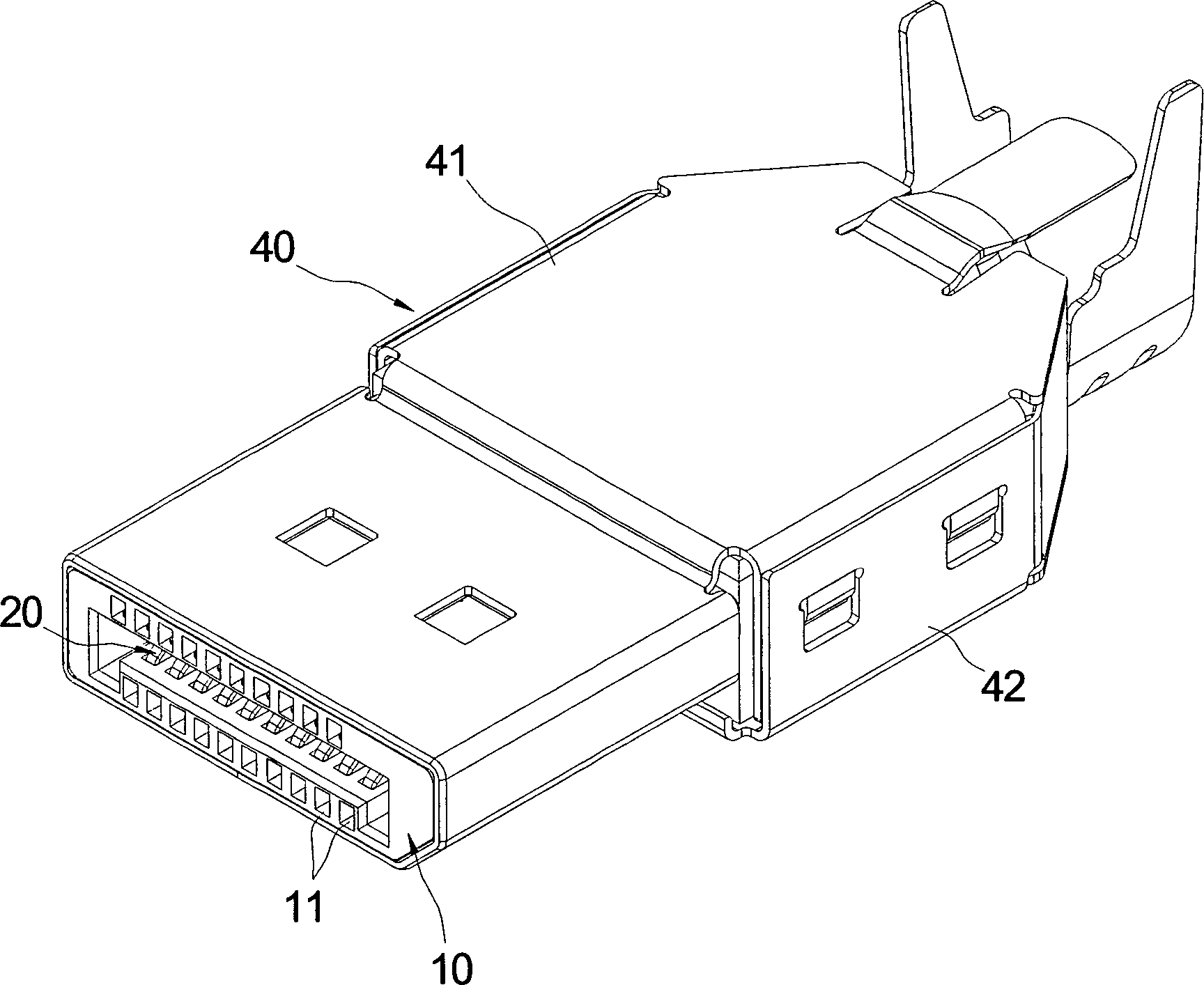
(10) einrastet.Electrical connector consisting of
- A plastic inner part (10) which is provided with a plurality of connection holes (11) and a first locking part (13), wherein the first locking part (13) at the rear end of the plastic inner part (10) is arranged;
- A plurality of conductive terminals (20) which are inserted in the connection holes (11) of the plastic inner part (10); and
- A rear plug-in part (30) which is latched in the rear end of the plastic inner part (10), wherein the front end of the rear plug part (30) has a second latching part (35) which in the first latching part (13) of the plastic inner part ( 10) engages.
Description
Die vorliegende Erfindung betrifft einen elektrischen Verbinder, insbesondere einen elektrischen Verbinder, bei dem das Kunststoff-Innenteil und das hintere Steckteil ineinander rasten.The The present invention relates to an electrical connector, in particular an electrical connector, wherein the plastic inner part and snap the rear plug into each other.
Durch die Popularität von elektronischen Geräten aller Type nimmt der Bedarf an Verbindungselementen zwischen elektronischen Geräten, also elektrischen Verbindern, ständig zu. Jedoch stellt sich für die betreffende Industrie die Aufgabe, einen elektrischen Verbinder zu schaffen, der gute elektrische Eigenschaften besitzt, leicht und schnell aufzubauen ist.By the popularity of electronic devices of all Type decreases the need for fasteners between electronic Devices, ie electrical connectors, constantly to. However, for the industry in question, the Task to create an electrical connector, the good electrical Has properties that is easy and quick to build.
Aus
dem US-amerikanischen Patent
Jedoch weist das herkömmlichen Aufbauverfahren des elektrischen Verbinders folgende Nachteile auf: Um das hintere Steckteil stabil mit der Hinterseite des Kunststoff-Innenteils zu kombinieren, muß das Interferenzmass zwischen dem hinteren Steckteil und den Seitenwänden größer eingestellt werden, damit sie über eine genügende Rastkraft verfügen können. Dementsprechend muß der Benutzer mit größerer Kraft das hintere Steckteil in die Seitenwände einrasten lassen. Dies erschwert den Aufbau des hinteren Steckteils und der Seitenwände.however has the conventional construction method of the electric Connector the following disadvantages: To the rear plug-in stable to combine with the back of the plastic inner part, that must Interference measure between the rear plug-in part and the side walls be set larger so that they over can have a sufficient locking force. Accordingly, the user with larger Force the rear male part into the side walls to let. This complicates the construction of the rear male part and the Side walls.
Angesichts dessen hat der Erfinder sich mit dem Studium dieser Technik beschäftigt und sich an diesbezügliche Theorien angelehnt und letztendlich die vorliegende Erfindung hervorgebracht.in view of of which the inventor has dealt with the study of this technique and based on related theories and ultimately the present invention.
Der Erfindung liegt die Aufgabe zugrunde, einen elektrischen Verbinder zu schaffen, bestehend aus: einem Kunststoff-Innenteil, das mit einer Vielzahl von Anschlusslöchern und einem ersten Rastteil versehen ist, wobei das erste Rastteil am Hinterende des Kunststoff-Innenteils angeordnet ist; einer Vielzahl von leitfähigen Anschlüssen, die in den Anschlusslöchern des Kunststoff-Innenteils eingesteckt sind; und einem hinteren Steckteil, der im Hinterende des Kunststoff-Innenteils eingerastet ist, wobei das Vorderende des hinteren Steckteils ein zweites Rastteil aufweist, das ins erste Rastteil des Kunststoff-Innenteils einrastet.Of the Invention is based on the object, an electrical connector to create, consisting of: a plastic inner part that with a plurality of connection holes and a first locking part provided is, wherein the first locking part at the rear end of the plastic inner part is arranged; a plurality of conductive terminals, which are inserted in the connection holes of the plastic inner part; and a rear male part, in the rear end of the plastic inner part is engaged, with the front end of the rear male part has second locking part, the first locking part of the plastic inner part locks.
Die vorliegende Erfindung weist folgende Vorteile auf:
- 1. beim Anbringen des hinteren Steckteils an das Hinterende des Kunststoff-Innenteils braucht der Benutzer lediglich das zweite Rastteil des hinteren Steckteils an das erste Rastteil einzuschieben, um die beiden Rastteile in Verrastung zu bringen und den Aufbau zu vollenden, wodurch der Aufbau des hinteren Steckteils und des Kunststoff-Innenteils schneller erfolgt; und
- 2. ohne große Kraft kann der Benutzer das zweite Rastteil zum ersten Rastteil hin derart schieben, dass die beiden Rastteile in Verrastung kommen, wodurch der Aufbau des hinteren Steckteils und des Kunststoff-Innenteils leichter durchzuführen ist.
- 1. when attaching the rear male part to the rear end of the plastic inner part, the user only needs to insert the second locking part of the rear male part to the first locking part to lock the two locking parts and complete the structure, whereby the structure of the rear male part and the plastic inner part is faster; and
- 2. without much force, the user can push the second locking part to the first locking part out such that the two locking parts come into locking, whereby the structure of the rear male part and the plastic inner part is easier to perform.
Im Folgenden werden die eingesetzten technischen Inhalte, Maßnahmen und Funktionen der vorliegenden Erfindung anhand der detaillierten Beschreibung und der beigefügten Zeichnungen näher erläutert werden. Jedoch ist die Erfindung nicht auf die Beschreibung und die beigefügten Zeichnungen beschränkt. Es zeigen:in the Following are the used technical contents, measures and functions of the present invention with reference to the detailed Description and the accompanying drawings explained in more detail become. However, the invention is not limited to the description and limited the accompanying drawings. Show it:
Wie
aus
Wie
aus
Die
leitfähigen Anschlüsse
Wie
aus
Das
hintere Steckteil
Die
Anschlussrinnen
Das
zweite Rastteil
Wenn
das hintere Steckteil
Die
beiden Seitenwände
Nachdem
das Kunststoff-Innenteil
Des
Weiteren ist an den beiden Seiten des Eisengehäuses
Die
Erfindung weist folgende Vorteile auf: 1. beim Anbringen des hinteren
Steckteils
Die vorstehende Beschreibung stellt nur ein bevorzugtes Ausführungsbeispiel der Erfindung dar und soll nicht die Patentansprüche beschränken. Alle gleichwertigen Änderungen und Modifikationen, die gemäß der Beschreibung und den Zeichnungen der Erfindung von einem Fachmann vorgenommen werden können, gehören zum Schutzbereich der vorliegenden Erfindung.The The above description represents only a preferred embodiment of the invention and is not intended to limit the claims. All equivalent changes and modifications made in accordance with the Description and drawings of the invention by a person skilled in the art can be made belong to the protected area of the present invention.
- 1010
- Kunststoff-InnenteilPlastic inner part
- 1111
- AnschlusslochMounting hole
- 1212
- SeitenwandSide wall
- 121121
- Positionieraussparungpositioning recess
- 1313
- erstes Rastteilfirst catch part
- 131131
- Rasthakenlatch hook
- 2020
- leitfähiger Anschlußconductive Connection
- 3030
- hinteres Steckteilrear male member
- 3131
- Zungenteiltongue member
- 3232
- DurchgangslochThrough Hole
- 3333
- Anschlussrinneconnecting channel
- 3434
- Positionierstückpositioning piece
- 3535
- zweites Rastteilsecond catch part
- 351351
- Rastbuchselocking bush
- 4040
- Eisengehäuseiron housing
- 4141
- oberes Gehäuseupper casing
- 4242
- unteres Gehäuselower casing
- 4343
- RückgangsperrscheibeDecline locking disk
ZITATE ENTHALTEN IN DER BESCHREIBUNGQUOTES INCLUDE IN THE DESCRIPTION
Diese Liste der vom Anmelder aufgeführten Dokumente wurde automatisiert erzeugt und ist ausschließlich zur besseren Information des Lesers aufgenommen. Die Liste ist nicht Bestandteil der deutschen Patent- bzw. Gebrauchsmusteranmeldung. Das DPMA übernimmt keinerlei Haftung für etwaige Fehler oder Auslassungen.This list The documents listed by the applicant have been automated generated and is solely for better information recorded by the reader. The list is not part of the German Patent or utility model application. The DPMA takes over no liability for any errors or omissions.
Zitierte PatentliteraturCited patent literature
- - US 6997733 [0003] - US 6997733 [0003]
Claims (10)
Priority Applications (1)
| Application Number | Priority Date | Filing Date | Title |
|---|---|---|---|
| DE202008009895U DE202008009895U1 (en) | 2008-07-23 | 2008-07-23 | Electrical connector |
Applications Claiming Priority (1)
| Application Number | Priority Date | Filing Date | Title |
|---|---|---|---|
| DE202008009895U DE202008009895U1 (en) | 2008-07-23 | 2008-07-23 | Electrical connector |
Publications (1)
| Publication Number | Publication Date |
|---|---|
| DE202008009895U1 true DE202008009895U1 (en) | 2008-09-11 |
Family
ID=39744727
Family Applications (1)
| Application Number | Title | Priority Date | Filing Date |
|---|---|---|---|
| DE202008009895U Expired - Lifetime DE202008009895U1 (en) | 2008-07-23 | 2008-07-23 | Electrical connector |
Country Status (1)
| Country | Link |
|---|---|
| DE (1) | DE202008009895U1 (en) |
Citations (1)
| Publication number | Priority date | Publication date | Assignee | Title |
|---|---|---|---|---|
| US6997733B2 (en) | 2004-04-09 | 2006-02-14 | Advanced Connectek Inc. | Electrical connector assembly with shroud and positioning device |
-
2008
- 2008-07-23 DE DE202008009895U patent/DE202008009895U1/en not_active Expired - Lifetime
Patent Citations (1)
| Publication number | Priority date | Publication date | Assignee | Title |
|---|---|---|---|---|
| US6997733B2 (en) | 2004-04-09 | 2006-02-14 | Advanced Connectek Inc. | Electrical connector assembly with shroud and positioning device |
Similar Documents
| Publication | Publication Date | Title |
|---|---|---|
| DE69302355T2 (en) | Electrical connector with contact positioning and position securing system | |
| DE69900770T2 (en) | Lateral locking electrical connector | |
| EP2182592B1 (en) | Connector | |
| DE10037457B4 (en) | Connection structure of a plug | |
| DE112004000102B4 (en) | Cassette relay block attachment structure | |
| EP1263091A2 (en) | 90 turnable connector | |
| DE60108333T2 (en) | Electrical connector | |
| DE2704760C2 (en) | ||
| DE10203162A1 (en) | Interconnects | |
| DE10204006B4 (en) | Multiple Connectors | |
| DE102015209049B4 (en) | electrical connector | |
| DE102009022094A1 (en) | stacking connector | |
| DE10204014A1 (en) | Interconnects | |
| DE10119695B4 (en) | Connectors for electronic components | |
| DE102010029192B4 (en) | Connector and plug-in module system | |
| DE102007053722A1 (en) | Hermaphroditic connector | |
| DE112014001976T5 (en) | Electronic component mounting structure and electrical junction box | |
| DE202015100696U1 (en) | Arrangement of several locking feet for an assembly and assembly | |
| DE2338778B2 (en) | Female connector | |
| CH621000A5 (en) | Optical fibre coupling | |
| DE102005059990B4 (en) | Connector for connecting electronic components | |
| DE69800376T2 (en) | Electrical connector with coding | |
| DE69306620T2 (en) | Socket and electrical coupling device | |
| EP2795732B1 (en) | Electrical contact element comprising a latching lance for a plug housing | |
| DE202008009895U1 (en) | Electrical connector |
Legal Events
| Date | Code | Title | Description |
|---|---|---|---|
| R207 | Utility model specification |
Effective date: 20081016 |
|
| R156 | Lapse of ip right after 3 years |
Effective date: 20120201 |