DE202008009829U1 - Contactless illuminated display device for means of transport - Google Patents
Contactless illuminated display device for means of transport Download PDFInfo
- Publication number
- DE202008009829U1 DE202008009829U1 DE202008009829U DE202008009829U DE202008009829U1 DE 202008009829 U1 DE202008009829 U1 DE 202008009829U1 DE 202008009829 U DE202008009829 U DE 202008009829U DE 202008009829 U DE202008009829 U DE 202008009829U DE 202008009829 U1 DE202008009829 U1 DE 202008009829U1
- Authority
- DE
- Germany
- Prior art keywords
- contactless
- display device
- illuminated display
- circuit
- transport
- Prior art date
- Legal status (The legal status is an assumption and is not a legal conclusion. Google has not performed a legal analysis and makes no representation as to the accuracy of the status listed.)
- Expired - Lifetime
Links
- 230000006698 induction Effects 0.000 claims abstract description 16
- 238000012545 processing Methods 0.000 claims description 10
- XLYOFNOQVPJJNP-UHFFFAOYSA-N water Substances O XLYOFNOQVPJJNP-UHFFFAOYSA-N 0.000 claims description 6
- 230000002146 bilateral effect Effects 0.000 description 4
- 230000000875 corresponding effect Effects 0.000 description 4
- 238000005259 measurement Methods 0.000 description 4
- 230000008054 signal transmission Effects 0.000 description 4
- 235000019504 cigarettes Nutrition 0.000 description 3
- 239000000428 dust Substances 0.000 description 3
- 230000005540 biological transmission Effects 0.000 description 2
- 230000000694 effects Effects 0.000 description 2
- 230000002159 abnormal effect Effects 0.000 description 1
- 238000010586 diagram Methods 0.000 description 1
- 230000005611 electricity Effects 0.000 description 1
- 238000011156 evaluation Methods 0.000 description 1
- 238000012986 modification Methods 0.000 description 1
- 230000004048 modification Effects 0.000 description 1
- 238000012546 transfer Methods 0.000 description 1
Classifications
-
- B—PERFORMING OPERATIONS; TRANSPORTING
- B60—VEHICLES IN GENERAL
- B60Q—ARRANGEMENT OF SIGNALLING OR LIGHTING DEVICES, THE MOUNTING OR SUPPORTING THEREOF OR CIRCUITS THEREFOR, FOR VEHICLES IN GENERAL
- B60Q7/00—Arrangement or adaptation of portable emergency signal devices on vehicles
-
- B—PERFORMING OPERATIONS; TRANSPORTING
- B60—VEHICLES IN GENERAL
- B60Q—ARRANGEMENT OF SIGNALLING OR LIGHTING DEVICES, THE MOUNTING OR SUPPORTING THEREOF OR CIRCUITS THEREFOR, FOR VEHICLES IN GENERAL
- B60Q3/00—Arrangement of lighting devices for vehicle interiors; Lighting devices specially adapted for vehicle interiors
- B60Q3/20—Arrangement of lighting devices for vehicle interiors; Lighting devices specially adapted for vehicle interiors for lighting specific fittings of passenger or driving compartments; mounted on specific fittings of passenger or driving compartments
- B60Q3/217—Doors, e.g. door sills; Steps
-
- B—PERFORMING OPERATIONS; TRANSPORTING
- B60—VEHICLES IN GENERAL
- B60Q—ARRANGEMENT OF SIGNALLING OR LIGHTING DEVICES, THE MOUNTING OR SUPPORTING THEREOF OR CIRCUITS THEREFOR, FOR VEHICLES IN GENERAL
- B60Q3/00—Arrangement of lighting devices for vehicle interiors; Lighting devices specially adapted for vehicle interiors
- B60Q3/50—Mounting arrangements
- B60Q3/59—Lighting devices mounted in the vehicle interior and adapted for portability
-
- B—PERFORMING OPERATIONS; TRANSPORTING
- B60—VEHICLES IN GENERAL
- B60Q—ARRANGEMENT OF SIGNALLING OR LIGHTING DEVICES, THE MOUNTING OR SUPPORTING THEREOF OR CIRCUITS THEREFOR, FOR VEHICLES IN GENERAL
- B60Q3/00—Arrangement of lighting devices for vehicle interiors; Lighting devices specially adapted for vehicle interiors
- B60Q3/80—Circuits; Control arrangements
-
- B—PERFORMING OPERATIONS; TRANSPORTING
- B60—VEHICLES IN GENERAL
- B60Q—ARRANGEMENT OF SIGNALLING OR LIGHTING DEVICES, THE MOUNTING OR SUPPORTING THEREOF OR CIRCUITS THEREFOR, FOR VEHICLES IN GENERAL
- B60Q2900/00—Features of lamps not covered by other groups in B60Q
- B60Q2900/30—Lamps commanded by wireless transmissions
Landscapes
- Engineering & Computer Science (AREA)
- Mechanical Engineering (AREA)
- Lighting Device Outwards From Vehicle And Optical Signal (AREA)
- Circuit Arrangement For Electric Light Sources In General (AREA)
- Audible And Visible Signals (AREA)
- Arrangement Of Elements, Cooling, Sealing, Or The Like Of Lighting Devices (AREA)
Abstract
Kontaktlose
Leuchtanzeigevorrichtung für
Transportmittel, bestehend mindestens aus
einer Leuchteinheit
(11), und
einer ersten Induktionsspule (12), die kontaktlos
mit einem Sensor (20) des Transportmittels (100) einen Strom erzeugen
kann.Contactless illuminated display device for means of transport, consisting of at least one
a lighting unit (11), and
a first induction coil (12), the contactless with a sensor (20) of the transport means (100) can generate a current.
Description
Technisches GebietTechnical area
Die Erfindung betrifft eine kontaktlose Leuchtanzeigevorrichtung für Transportmittel, das Auto, Schiff, Flugzeug, Träger, Sensorhalterung usw. sein kann, wobei die kontaktlose Leuchtanzeigevorrichtung auch von dem Transportmittel getrennt und unabhängig benutzt werden kann.The The invention relates to a contactless illuminated display device for means of transport, the car, ship, plane, carrier, Sensor holder, etc. may be, wherein the contactless illuminated display device also separated from the means of transport and can be used independently.
Stand der TechnikState of the art
Transportmittel, wie Auto, Schiff, Flugzeug, Träger, Sensorhalterung, kann mit einer Leuchtanzeigevorrichtung versehen, um eine Beleuchtungs-, Warn- oder Anzeigewirkung zu erzeugen. Diese Leuchtanzeigevorrichtung ist z. B. eine Blinklampe, eine Leselampe und eine abnehmbare Lampe, die in den Zigarettenanzünder des Autos gesteckt werden kann.Mode of Transport, like car, ship, plane, carrier, Sensor holder, can be provided with a light display device, to produce a lighting, warning or display effect. This light display device is z. A flashing lamp, a reading lamp and a removable lamp, in the cigarette lighter of the car can be plugged.
Die Leuchtanzeigevorrichtung wird von dem Transportmittel mit einem Strom versorgt und benötigtsomit elektrische Leitungen und Anschlüsse, um eine Strom- oder Signalübertragung durchzuführen. Durch die laterale oder bilaterale Signalübertragung zwischen der Leuchtanzeigevorrichtung und dem Transportmittel können Meßsignale oder Steuersignale übertragen werden. Z. B. das Transportmittel kann entsprechend einem Meßsignal das Blinken der Blinklampe steuern.The Illuminated display device is from the transport with a Power supplied and thus needed electrical lines and connections, to a power or signal transmission perform. By the lateral or bilateral signal transmission between the illuminated display device and the means of transport measuring signals or transmit control signals become. For example, the means of transport may be in accordance with a measurement signal control the flashing of the flashing lamp.
Die elektrische Verbindung zwischen der Leuchtanzeigevorrichtung und dem Transportmittel erfolgt durch die elektrischen Leitungen. Diese elektrische Verbindung weist jedoch folgende Nachteile auf:
- 1. eine Kabelverlegung zwischen der Leuchtanzeigevorrichtung und dem Transportmittel ist erforderlich;
- 2. wenn die Dichtungen für Wasser- und Staubschutz altern, kann ein Wasser- oder Staubeintritt auftreten;
- 3. die Leuchtanzeigevorrichtung kann nicht unabhängig von dem Transportmittel benutzt werden.
- 1. a cable routing between the light-emitting device and the means of transport is required;
- 2. if the seals for water and dust protection age, water or dust may occur;
- 3. The illuminated display device can not be used independently of the means of transport.
Aus diesem Grund hat der Erfinder die vorliegende Erfindung entwickelt.Out For this reason, the inventor has developed the present invention.
Aufgabe der ErfindungObject of the invention
Der Erfindung liegt die Aufgabe zugrunde, eine kontaktlose Leuchtanzeigevorrichtung für Transportmittel zu schaffen, die durch Funkfrenquenz mit dem Transportmittel einen Strom erzeugen und mit dem Transportmittel eine laterale oder bilaterale Signalübertragung durchführen kann, so dass eine Übertragung von z. B. Meßsignalen und Steuersignalen möglich ist.Of the Invention is based on the object, a contactless illuminated display device for means of transport to create by radio frequency with the means of transport Generate electricity and with the means of transport a lateral or bilateral signal transmission carry out can, so a transmission from Z. B. measuring signals and control signals possible is.
Diese Aufgabe wird durch die erfindungsgemäße kontaktlose Leuchtanzeigevorrichtung für Transportmittel gelöst, die bestehend mindestens aus einer Leuchteinheit und einer ersten Induktionsspule, die kontaktlos mit einem Sensor des Transportmittels einen Strom erzeugen kann. Der Sensor des Transportmittels weist eine zweite Induktionsspule auf, die mit der ersten Induktionsspule ein Magnetfeld oder einen Funkfrequenzbereich erzeugen kann.These The object is achieved by the contactless illuminated display device according to the invention for means of transport solved, consisting of at least one lighting unit and a first Induction coil, which is contactless with a sensor of the means of transport can generate a current. The sensor of the means of transport points a second induction coil connected to the first induction coil can generate a magnetic field or a radio frequency range.
Damit durch Funkfrequenz in der kontaktlosen Leuchtanzeigevorrichtung ein Strom induziert wird, wenn die kontaktlose Leuchtanzeigevorrichtung in den Wirkungsbereich des Sensors eintritt, kann die kontaktlose Leuchtanzeigevorrichtung ferner eine erste Resonanzschaltung und der Sensor ferner eine zweite Induktionsspule, eine zweite Resonanzschaltung, eine Verstärkerschaltung und eine Oszillatorschaltung aufweisen.In order to by radio frequency in the contactless illuminated display device a current is induced when the contactless light-emitting device in enters the sphere of action of the sensor, the contactless illuminated display device Further, a first resonant circuit and the sensor further comprises a second Induction coil, a second resonant circuit, an amplifier circuit and an oscillator circuit.
Damit die kontaktlose Leuchtanzeigevorrichtung unabhängig ein- und ausgeschaltet werden kann, kann sie noch eine Stromschaltung, einen Schalter und eine erste Steuerschaltung aufweisen.In order to the contactless illuminated display device independently turned on and off can still be a power circuit, a switch and have a first control circuit.
Damit die kontaktlose Leuchtanzeigevorrichtung ein Meßsignal oder Steuersginal für das Transportmittel erzeugen kann, kann die kontaktlose Leuchtanzeigevorrichtung ferner eine Modulationsschaltung und der Sensor ferner eine zweite Signalverarbeitungsschaltung, eine zweite Steuerschaltung und eine Rückkoppelschaltung aufweisen.In order to the contactless illuminated display device, a measurement signal or control certificate for the means of transport can produce, the non-contact light emitting device further a modulation circuit and the sensor further comprises a second signal processing circuit, a second control circuit and a feedback circuit.
Damit das Transportmittel oder der Sensor ein Steuersignal an die kontaktlosen Leuchtanzeigevorrichtung zurücksenden kann, kann die kontaktlose Leuchtanzeigevorrichtung ferner ein erste Signalverarbeitungsschaltung und der Sensor ferner eine Trägerschaltung aufweisen.In order to the means of transport or the sensor sends a control signal to the contactless ones Return the illuminated display device can, the non-contact light-emitting device further comprises a first Signal processing circuit and the sensor further comprises a carrier circuit exhibit.
Damit die kontaktlose Leuchtanzeigevorrichtung weiterhin mit einem Strom versorgt wird, wenn sie den Wirkungsbereich des Sensors verläßt, kann die kontaktlose Leuchtanzeigevorrichtung eine Ladeschaltung und einen Akku aufweisen. Wenn das Transportmittel ein Auto ist, kann die kontaktlose Leuchtanzeigevorrichtung eine tragbare Lampe sein. In den Zigarettenanzünder des Autos wird eine Halterung gesteckt, in dem der Sensor angeordnet ist. Wenn die kontaktlose Leuchtanzeigevorrichtung an der Halterung befestigt ist, kann durch den Sensor in der kontaktlosen Leuchtanzeigevorrichtung ein Strom induziert werden, wodurch die kontaktlose Leuchtanzeigevorrichtung ein Licht erzeugen kann (wie als Leselampe). Wenn die kontaktlose Leuchtanzeigevorrichtung von der Halterung getrennt wird, kann sie als Taschenlampe verwendet werden.In order to the non-contact light-emitting device further with a current is supplied, when it leaves the sphere of action of the sensor, the contactless illuminated display device, a charging circuit and a Have battery. If the means of transport is a car, the contactless light display device to be a portable lamp. In the cigarette lighter the car is put a holder in which the sensor is arranged is. When the contactless light display device on the holder is fixed by the sensor in the contactless light display device a current are induced, whereby the non-contact luminous display device can produce a light (as a reading lamp). If the contactless Light indicator is disconnected from the holder, it can be used as a flashlight.
Im Vergleich mit der herkömmlichen Lösung weist die Erfindung folgende Vorteile auf:
- 1. da die kontaktlose Leuchtanzeigevorrichtung keine elektrische Leitungen und Anschlüsse benötigt, kann sie leicht mit dem Transportmittel verbunden und von diesem getrennt werden;
- 2. da die kontaktlose Leuchtanzeigevorrichtung keine elektrische Leitungen und Anschlüsse benötigt, ist eine Kabelverlegung nicht erfordlich;
- 3. da die kontaktlose Leuchtanzeigevorrichtung keine elektrische Leitungen und Anschlüsse benötigt, kann ein besserer Wasser- und Staubschutz erreicht werden;
- 4. wenn die kontaktlose Leuchtanzeigevorrichtung von dem Transportmittel getrennt wird, kann sie mit dem Akku betrieben und unabhängig benutzt werden;
- 5. eine laterale oder bilaterale Signalübertragung zwischen der kontaktlosen Leuchtanzeigevorrichtung und dem Transportmittel ist möglich.
- 1. Since the contactless light display device requires no electrical lines and connections, it can be easily connected to the transport and separated from it;
- 2. Since the non-contact light-emitting device does not require electrical lines and connections, cable laying is not required;
- 3. since the contactless light display device requires no electrical lines and connections, better water and dust protection can be achieved;
- 4. If the contactless light display device is disconnected from the means of transport, it can be operated with the battery and used independently;
- 5. a lateral or bilateral signal transmission between the contactless light display device and the means of transport is possible.
Kurze Beschreibung der ZeichnungenBrief description of the drawings
Wege zur Ausführung der ErfindungWays to execute the invention
Im folgenden wird die Erfindung anhand der beigefügten Zeichnungen näher erläutert.in the Following, the invention will be explained in more detail with reference to the accompanying drawings.
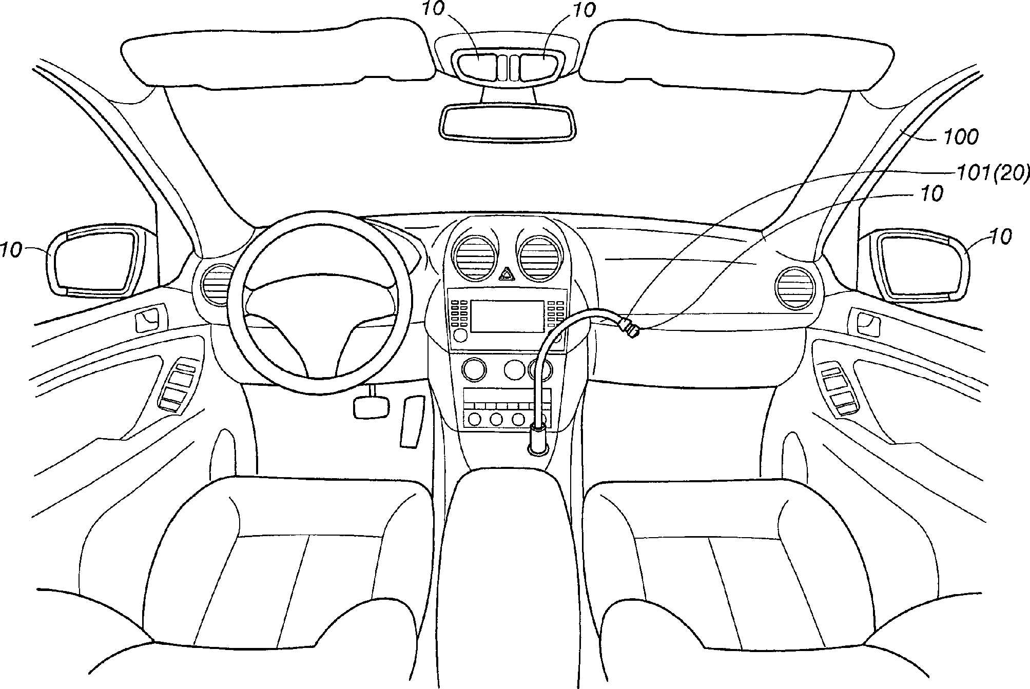
In
Wenn
die kontaktlose Leuchtanzeigevorrichtung
Wenn
die erste Steuerschaltung
Damit
die kontaktlose Leuchtanzeigevorrichtung
Wie
aus
Wie
aus
Wie
aus
Die vorstehende Beschreibung stellt nur die bevorzugten Ausführungsbeispiele der Erfindung dar und soll nicht als Definition der Grenzen und des Bereiches der Erfindung dienen. Alle gleichwertige Änderungen und Modifikationen gehören zum Schutzbereich dieser Erfindung.The The above description represents only the preferred embodiments of the invention and should not be used as a definition of boundaries and serve the scope of the invention. All equivalent changes and modifications are included to the scope of this invention.
- 100100
- TransportmittelMode of Transport
- 101101
- Halterungbracket
- 1010
- kontaktlose Leuchtanzeigevorrichtungcontactless Illuminated display device
- 1111
- Leuchteinheitlight unit
- 1212
- erste Induktionsspulefirst induction coil
- 1313
- erste Resonanzschaltungfirst resonant circuit
- 1414
- Stromschaltungcurrent circuit
- 1515
- Schalterswitch
- 1616
- erste Steuerschaltungfirst control circuit
- 1717
- Modulationsschaltungmodulation circuit
- 1818
- erste Signalverarbeitungsschaltungfirst Signal processing circuit
- 1919
- Ladeschaltungcharging circuit
- 191191
- Akkubattery pack
- 2020
- Sensorsensor
- 2121
- zweite Induktionsspulesecond induction coil
- 2222
- zweite Resonanzschaltungsecond resonant circuit
- 2323
- Verstärkerschaltungamplifier circuit
- 2424
- Oszillatorschaltungoscillator circuit
- 241241
- modulierbarer Oszillatormodulatable oscillator
- 2525
- zweite Signalverarbeitungsschaltungsecond Signal processing circuit
- 2626
- zweite Steuerschaltungsecond control circuit
- 2727
- RückkoppelschaltungFeedback circuit
- 2828
- Trägerschaltungcarrier circuit
Claims (10)
Applications Claiming Priority (2)
| Application Number | Priority Date | Filing Date | Title |
|---|---|---|---|
| CN200710142807.9 | 2007-07-27 | ||
| CN2007101428079A CN101089462B (en) | 2007-07-27 | 2007-07-27 | Non-contact light-emitting display device of carrier |
Publications (1)
| Publication Number | Publication Date |
|---|---|
| DE202008009829U1 true DE202008009829U1 (en) | 2008-10-23 |
Family
ID=38942913
Family Applications (1)
| Application Number | Title | Priority Date | Filing Date |
|---|---|---|---|
| DE202008009829U Expired - Lifetime DE202008009829U1 (en) | 2007-07-27 | 2008-07-22 | Contactless illuminated display device for means of transport |
Country Status (4)
| Country | Link |
|---|---|
| US (1) | US20090026959A1 (en) |
| JP (1) | JP3145419U (en) |
| CN (1) | CN101089462B (en) |
| DE (1) | DE202008009829U1 (en) |
Cited By (4)
| Publication number | Priority date | Publication date | Assignee | Title |
|---|---|---|---|---|
| EP2511136A1 (en) * | 2011-04-13 | 2012-10-17 | Volvo Car Corporation | Illumination system for vehicle boot |
| DE102017109616A1 (en) * | 2017-05-04 | 2018-11-08 | Osram Oled Gmbh | Optoelectronic arrangement for a motor vehicle and motor vehicle |
| DE102018204329A1 (en) * | 2018-03-21 | 2019-09-26 | Zf Friedrichshafen Ag | Outdoor lighting for a motor vehicle |
| DE102016124570B4 (en) | 2015-12-30 | 2024-04-25 | GM Global Technology Operations LLC | METHOD AND DEVICE FOR WIRELESS COMMUNICATION AND POWER TRANSFER FOR AN EXTERNAL BOARD LIGHT |
Families Citing this family (28)
| Publication number | Priority date | Publication date | Assignee | Title |
|---|---|---|---|---|
| MX2009008011A (en) | 2007-01-29 | 2010-02-18 | Powermat Ltd | Pinless power coupling. |
| CN102106054A (en) | 2007-03-22 | 2011-06-22 | 鲍尔马特有限公司 | Signal transfer system |
| AU2008303118A1 (en) * | 2007-09-25 | 2009-04-02 | Powermat Technologies Ltd. | Inductive power transmission platform |
| US10068701B2 (en) | 2007-09-25 | 2018-09-04 | Powermat Technologies Ltd. | Adjustable inductive power transmission platform |
| US8193769B2 (en) * | 2007-10-18 | 2012-06-05 | Powermat Technologies, Ltd | Inductively chargeable audio devices |
| US8536737B2 (en) * | 2007-11-19 | 2013-09-17 | Powermat Technologies, Ltd. | System for inductive power provision in wet environments |
| US20100219183A1 (en) * | 2007-11-19 | 2010-09-02 | Powermat Ltd. | System for inductive power provision within a bounding surface |
| KR20100130215A (en) | 2008-03-17 | 2010-12-10 | 파우워매트 엘티디. | Inductive transmission system |
| US9960640B2 (en) | 2008-03-17 | 2018-05-01 | Powermat Technologies Ltd. | System and method for regulating inductive power transmission |
| US9960642B2 (en) | 2008-03-17 | 2018-05-01 | Powermat Technologies Ltd. | Embedded interface for wireless power transfer to electrical devices |
| US9337902B2 (en) | 2008-03-17 | 2016-05-10 | Powermat Technologies Ltd. | System and method for providing wireless power transfer functionality to an electrical device |
| US9331750B2 (en) | 2008-03-17 | 2016-05-03 | Powermat Technologies Ltd. | Wireless power receiver and host control interface thereof |
| US8320143B2 (en) | 2008-04-15 | 2012-11-27 | Powermat Technologies, Ltd. | Bridge synchronous rectifier |
| CA2726552A1 (en) | 2008-06-02 | 2009-12-10 | Powermat Ltd. | Appliance mounted power outlets |
| US8981598B2 (en) | 2008-07-02 | 2015-03-17 | Powermat Technologies Ltd. | Energy efficient inductive power transmission system and method |
| US8188619B2 (en) | 2008-07-02 | 2012-05-29 | Powermat Technologies Ltd | Non resonant inductive power transmission system and method |
| US11979201B2 (en) | 2008-07-02 | 2024-05-07 | Powermat Technologies Ltd. | System and method for coded communication signals regulating inductive power transmissions |
| AU2009269574A1 (en) | 2008-07-08 | 2010-01-14 | Powermat Technologies Ltd. | Display device |
| AU2009297963A1 (en) | 2008-09-23 | 2010-04-01 | Powermat Technologies Ltd. | Combined antenna and inductive power receiver |
| CN102400485B (en) * | 2010-09-07 | 2014-12-17 | 克塞尔股份公司 | Draining facility assembly |
| TWM400964U (en) * | 2010-09-29 | 2011-04-01 | chang-sheng Liu | Light-emitting device for cars |
| JP2013023077A (en) * | 2011-07-21 | 2013-02-04 | Koito Mfg Co Ltd | Power supply device for vehicle lamp |
| JP5958899B2 (en) * | 2012-07-02 | 2016-08-02 | 株式会社湘南工作所 | Portable daytime signal lights for ships |
| DE102016110492A1 (en) * | 2016-06-07 | 2017-12-07 | Dr. Ing. H.C. F. Porsche Aktiengesellschaft | Motor vehicle with a raised brake light |
| CN106205483A (en) * | 2016-08-31 | 2016-12-07 | 何建军 | A kind of advertisement light emitting device |
| US10144345B2 (en) * | 2016-11-23 | 2018-12-04 | Ford Global Technologies, Llc | Illuminated running board |
| US10690295B2 (en) * | 2017-07-12 | 2020-06-23 | Global Navigation Sciences, Inc. | Apparatus with computer interface module for use in vehicles |
| DE102017007060B4 (en) * | 2017-07-26 | 2022-06-30 | Audi Ag | Arrangement of a device for receiving an object in a motor vehicle and an object |
Family Cites Families (7)
| Publication number | Priority date | Publication date | Assignee | Title |
|---|---|---|---|---|
| US4390974A (en) * | 1981-01-08 | 1983-06-28 | Litton Resources Systems, Inc. | Seismic data telemetric system |
| US4914399A (en) * | 1989-03-01 | 1990-04-03 | Minnesota Mining And Manufacturing Company | Induction coil driver |
| US6825620B2 (en) * | 1999-06-21 | 2004-11-30 | Access Business Group International Llc | Inductively coupled ballast circuit |
| NZ528542A (en) * | 2003-09-29 | 2006-09-29 | Auckland Uniservices Ltd | Inductively-powered power transfer system with one or more, independently controlled loads |
| CN100403241C (en) * | 2004-12-09 | 2008-07-16 | 张定港 | Non-contact power supply induction circuit and application thereof |
| CN2884658Y (en) * | 2005-04-26 | 2007-03-28 | 张定港 | Illumination/display device using non-contact induction power supply |
| US20070170872A1 (en) * | 2006-01-20 | 2007-07-26 | Cheng-Chia Hsu | Control device for multiple lamp currents of liquid crystal display backlight source |
-
2007
- 2007-07-27 CN CN2007101428079A patent/CN101089462B/en not_active Expired - Fee Related
-
2008
- 2008-07-22 DE DE202008009829U patent/DE202008009829U1/en not_active Expired - Lifetime
- 2008-07-23 JP JP2008005056U patent/JP3145419U/en not_active Expired - Fee Related
- 2008-07-28 US US12/219,712 patent/US20090026959A1/en not_active Abandoned
Cited By (4)
| Publication number | Priority date | Publication date | Assignee | Title |
|---|---|---|---|---|
| EP2511136A1 (en) * | 2011-04-13 | 2012-10-17 | Volvo Car Corporation | Illumination system for vehicle boot |
| DE102016124570B4 (en) | 2015-12-30 | 2024-04-25 | GM Global Technology Operations LLC | METHOD AND DEVICE FOR WIRELESS COMMUNICATION AND POWER TRANSFER FOR AN EXTERNAL BOARD LIGHT |
| DE102017109616A1 (en) * | 2017-05-04 | 2018-11-08 | Osram Oled Gmbh | Optoelectronic arrangement for a motor vehicle and motor vehicle |
| DE102018204329A1 (en) * | 2018-03-21 | 2019-09-26 | Zf Friedrichshafen Ag | Outdoor lighting for a motor vehicle |
Also Published As
| Publication number | Publication date |
|---|---|
| CN101089462A (en) | 2007-12-19 |
| JP3145419U (en) | 2008-10-09 |
| CN101089462B (en) | 2010-06-02 |
| US20090026959A1 (en) | 2009-01-29 |
Similar Documents
| Publication | Publication Date | Title |
|---|---|---|
| DE202008009829U1 (en) | Contactless illuminated display device for means of transport | |
| EP2676531B1 (en) | Combined sensor/emergency light unit for a lighting system | |
| EP2048748B1 (en) | Device to be connected to a trailer outlet socket of a motor vehicle | |
| DE3108739A1 (en) | EMERGENCY LIGHTING UNIT | |
| EP2803143A1 (en) | Inductive energy supply unit | |
| DE102016003652A1 (en) | Connector for a motor vehicle and device of a motor vehicle with a Steckberbinder | |
| EP2561167A1 (en) | Exterior door handle with passive-entry subassemblies and a lighting subassembly | |
| DE102016000311A1 (en) | Charging socket arrangement for a motor vehicle and method | |
| DE202017103605U1 (en) | lighting device | |
| DE102014010414A1 (en) | Charging system for the electrical connection of a charging station with an electric car and method for its operation | |
| DE102020102530A1 (en) | Electronic two-wire home automation control device | |
| DE3818259C1 (en) | ||
| DE102019112797A1 (en) | Removable charging pad | |
| EP2941096A2 (en) | Lighting assembly with an operating device for providing an appropriate supply current | |
| DE102013022312A1 (en) | Charging system for the electrical connection of a charging station with an electric car and method for its operation | |
| DE4219999A1 (en) | Loading device | |
| DE102007022208B4 (en) | Multiple socket with phase indication | |
| DE202014104009U1 (en) | Test device for electrical lighting devices of a motor vehicle trailer | |
| DE156673C (en) | ||
| WO2016184933A1 (en) | Mains plug component and electric or electronic device | |
| EP0611918B1 (en) | Hand lamp with signal emitting elements of a remote control device | |
| DE10237621B4 (en) | Capacitive switch | |
| EP1826578B1 (en) | Device for checking an electrical circuit board with a track | |
| DE212012000217U1 (en) | Control device for controlling the dimensioning of a part | |
| DE102018133424A1 (en) | Presence control PE pantograph |
Legal Events
| Date | Code | Title | Description |
|---|---|---|---|
| R207 | Utility model specification |
Effective date: 20081127 |
|
| R082 | Change of representative |
Representative=s name: ZEITLER, VOLPERT, KANDLBINDER, 80539 MUENCHEN, DE |
|
| R156 | Lapse of ip right after 3 years |
Effective date: 20120201 |