DE202008009820U1 - Adjustment device for an adjustment part of a motor vehicle - Google Patents
Adjustment device for an adjustment part of a motor vehicle Download PDFInfo
- Publication number
- DE202008009820U1 DE202008009820U1 DE200820009820 DE202008009820U DE202008009820U1 DE 202008009820 U1 DE202008009820 U1 DE 202008009820U1 DE 200820009820 DE200820009820 DE 200820009820 DE 202008009820 U DE202008009820 U DE 202008009820U DE 202008009820 U1 DE202008009820 U1 DE 202008009820U1
- Authority
- DE
- Germany
- Prior art keywords
- driver
- guide rail
- end position
- adjustment
- spring
- Prior art date
- Legal status (The legal status is an assumption and is not a legal conclusion. Google has not performed a legal analysis and makes no representation as to the accuracy of the status listed.)
- Expired - Lifetime
Links
Classifications
-
- E—FIXED CONSTRUCTIONS
- E05—LOCKS; KEYS; WINDOW OR DOOR FITTINGS; SAFES
- E05F—DEVICES FOR MOVING WINGS INTO OPEN OR CLOSED POSITION; CHECKS FOR WINGS; WING FITTINGS NOT OTHERWISE PROVIDED FOR, CONCERNED WITH THE FUNCTIONING OF THE WING
- E05F11/00—Man-operated mechanisms for operating wings, including those which also operate the fastening
- E05F11/38—Man-operated mechanisms for operating wings, including those which also operate the fastening for sliding windows, e.g. vehicle windows, to be opened or closed by vertical movement
- E05F11/48—Man-operated mechanisms for operating wings, including those which also operate the fastening for sliding windows, e.g. vehicle windows, to be opened or closed by vertical movement operated by cords or chains or other flexible elongated pulling elements, e.g. tapes
- E05F11/481—Man-operated mechanisms for operating wings, including those which also operate the fastening for sliding windows, e.g. vehicle windows, to be opened or closed by vertical movement operated by cords or chains or other flexible elongated pulling elements, e.g. tapes for vehicle windows
- E05F11/483—Man-operated mechanisms for operating wings, including those which also operate the fastening for sliding windows, e.g. vehicle windows, to be opened or closed by vertical movement operated by cords or chains or other flexible elongated pulling elements, e.g. tapes for vehicle windows by cables
- E05F11/488—Man-operated mechanisms for operating wings, including those which also operate the fastening for sliding windows, e.g. vehicle windows, to be opened or closed by vertical movement operated by cords or chains or other flexible elongated pulling elements, e.g. tapes for vehicle windows by cables with two cable connections to the window glass
-
- E—FIXED CONSTRUCTIONS
- E05—LOCKS; KEYS; WINDOW OR DOOR FITTINGS; SAFES
- E05F—DEVICES FOR MOVING WINGS INTO OPEN OR CLOSED POSITION; CHECKS FOR WINGS; WING FITTINGS NOT OTHERWISE PROVIDED FOR, CONCERNED WITH THE FUNCTIONING OF THE WING
- E05F11/00—Man-operated mechanisms for operating wings, including those which also operate the fastening
- E05F11/38—Man-operated mechanisms for operating wings, including those which also operate the fastening for sliding windows, e.g. vehicle windows, to be opened or closed by vertical movement
- E05F11/48—Man-operated mechanisms for operating wings, including those which also operate the fastening for sliding windows, e.g. vehicle windows, to be opened or closed by vertical movement operated by cords or chains or other flexible elongated pulling elements, e.g. tapes
- E05F11/481—Man-operated mechanisms for operating wings, including those which also operate the fastening for sliding windows, e.g. vehicle windows, to be opened or closed by vertical movement operated by cords or chains or other flexible elongated pulling elements, e.g. tapes for vehicle windows
- E05F11/483—Man-operated mechanisms for operating wings, including those which also operate the fastening for sliding windows, e.g. vehicle windows, to be opened or closed by vertical movement operated by cords or chains or other flexible elongated pulling elements, e.g. tapes for vehicle windows by cables
- E05F11/485—Man-operated mechanisms for operating wings, including those which also operate the fastening for sliding windows, e.g. vehicle windows, to be opened or closed by vertical movement operated by cords or chains or other flexible elongated pulling elements, e.g. tapes for vehicle windows by cables with cable tensioners
-
- E—FIXED CONSTRUCTIONS
- E05—LOCKS; KEYS; WINDOW OR DOOR FITTINGS; SAFES
- E05Y—INDEXING SCHEME ASSOCIATED WITH SUBCLASSES E05D AND E05F, RELATING TO CONSTRUCTION ELEMENTS, ELECTRIC CONTROL, POWER SUPPLY, POWER SIGNAL OR TRANSMISSION, USER INTERFACES, MOUNTING OR COUPLING, DETAILS, ACCESSORIES, AUXILIARY OPERATIONS NOT OTHERWISE PROVIDED FOR, APPLICATION THEREOF
- E05Y2201/00—Constructional elements; Accessories therefor
- E05Y2201/40—Motors; Magnets; Springs; Weights; Accessories therefor
- E05Y2201/404—Function thereof
- E05Y2201/422—Function thereof for opening
- E05Y2201/424—Function thereof for opening for the final opening movement
-
- E—FIXED CONSTRUCTIONS
- E05—LOCKS; KEYS; WINDOW OR DOOR FITTINGS; SAFES
- E05Y—INDEXING SCHEME ASSOCIATED WITH SUBCLASSES E05D AND E05F, RELATING TO CONSTRUCTION ELEMENTS, ELECTRIC CONTROL, POWER SUPPLY, POWER SIGNAL OR TRANSMISSION, USER INTERFACES, MOUNTING OR COUPLING, DETAILS, ACCESSORIES, AUXILIARY OPERATIONS NOT OTHERWISE PROVIDED FOR, APPLICATION THEREOF
- E05Y2400/00—Electronic control; Electrical power; Power supply; Power or signal transmission; User interfaces
- E05Y2400/10—Electronic control
- E05Y2400/32—Position control, detection or monitoring
- E05Y2400/35—Position control, detection or monitoring related to specific positions
- E05Y2400/356—Intermediate positions
- E05Y2400/358—Intermediate positions in the proximity of end positions
-
- E—FIXED CONSTRUCTIONS
- E05—LOCKS; KEYS; WINDOW OR DOOR FITTINGS; SAFES
- E05Y—INDEXING SCHEME ASSOCIATED WITH SUBCLASSES E05D AND E05F, RELATING TO CONSTRUCTION ELEMENTS, ELECTRIC CONTROL, POWER SUPPLY, POWER SIGNAL OR TRANSMISSION, USER INTERFACES, MOUNTING OR COUPLING, DETAILS, ACCESSORIES, AUXILIARY OPERATIONS NOT OTHERWISE PROVIDED FOR, APPLICATION THEREOF
- E05Y2900/00—Application of doors, windows, wings or fittings thereof
- E05Y2900/50—Application of doors, windows, wings or fittings thereof for vehicles
- E05Y2900/508—Application of doors, windows, wings or fittings thereof for vehicles for convertibles
-
- E—FIXED CONSTRUCTIONS
- E05—LOCKS; KEYS; WINDOW OR DOOR FITTINGS; SAFES
- E05Y—INDEXING SCHEME ASSOCIATED WITH SUBCLASSES E05D AND E05F, RELATING TO CONSTRUCTION ELEMENTS, ELECTRIC CONTROL, POWER SUPPLY, POWER SIGNAL OR TRANSMISSION, USER INTERFACES, MOUNTING OR COUPLING, DETAILS, ACCESSORIES, AUXILIARY OPERATIONS NOT OTHERWISE PROVIDED FOR, APPLICATION THEREOF
- E05Y2900/00—Application of doors, windows, wings or fittings thereof
- E05Y2900/50—Application of doors, windows, wings or fittings thereof for vehicles
- E05Y2900/53—Type of wing
- E05Y2900/55—Windows
Landscapes
- Window Of Vehicle (AREA)
Abstract
Verstellvorrichtung für ein Verstellteil eines Kraftfahrzeugs, mit
– einer Führungsschiene,
– einer Antriebseinrichtung und
– einem entlang der Führungsschiene geführten Mitnehmer, der über ein Zugmittel mit der Antriebseinrichtung gekoppelt und zum Verstellen des Verstellteils aus einer Endposition an der Führungsschiene in eine Abwärtsrichtung entlang der Führungsschiene verschiebbar ist,
dadurch gekennzeichnet,
dass der mindestens eine Mitnehmer (14) in der Endposition an der Führungsschiene (11) über eine Vorspanneinrichtung (3) in die Abwärtsrichtung (RAB) vorgespannt ist.Adjustment device for an adjustment of a motor vehicle, with
A guide rail,
- A drive device and
A driver guided along the guide rail, which is coupled to the drive device by means of a traction mechanism and is displaceable in a downward direction along the guide rail for adjusting the adjustment part from an end position on the guide rail,
characterized,
that the at least one driver (14) in the end position on the guide rail (11) via a biasing means (3) in the downward direction (R AB ) is biased.
Description
Die Erfindung betrifft eine Verstellvorrichtung für ein Verstellteil eines Kraftfahrzeugs nach dem Oberbegriff des Anspruchs 1.The The invention relates to an adjusting device for an adjustment of a motor vehicle according to the preamble of claim 1.
Eine derartige Verstellvorrichtung weist eine Führungsschiene, eine Antriebseinheit und ein entlang der Führungsschiene geführten Mitnehmer auf, der über ein Zugmittel mit der Antriebseinrichtung gekoppelt und zum Verstellen des Verstellteils aus einer Endposition an der Führungsschiene in eine Abwärtsrichtung entlang der Führungsschiene verschiebbar ist.A Such adjustment device has a guide rail, a drive unit and a along the guide rail guided driver, who has a traction device coupled with the drive device and for adjusting the adjustment from an end position on the guide rail in a downward direction along the guide rail is displaceable.
Beispielsweise
weist eine aus der
Seilfensterheber einer rahmenlosen Fahrzeugtür besitzen herkömmlich eine Kurzhubfunktion, die ausgelegt ist, die zu verstellende Fensterscheibe der rahmenlosen Fahrzeugtür beim Öffnen der Fahrzeugtür automatisch aus der Dichtung der Fahrzeugtür zu fahren und so das Öffnen der Fahrzeugtür zu erleichtern und eine Beschädigung der Dichtung, der Fensterscheibe oder der Fahrzeugtür zu verhindern. Hierbei ist wesentlich, dass die Fensterscheibe beim Öffnen der Fahrzeugtür innerhalb kürzester Zeit aus der Dichtung herausbewegt wird, damit auch bei einem schnellen Öffnen der Fahrzeugtür die Fensterscheibe sicher und rechtzeitig aus der Dichtung gelangt. Dieser erforderlichen schnellen Verstellbewegung der Fensterscheibe steht jedoch die Elastizität des Seilfensterhebersystems, bedingt insbesondere durch die zum Zwecke des Seillängenausgleichs vorgesehene elastische Abstützung der Bowdenrohre mittels der elastischen Elemente, entgegen. Bei Einleitung des Verstellvorgangs muss diese Elastizität zunächst ausgeglichen werden. Erst anschließend können die Verstellkräfte auf das Verstellteil übertragen werden, so dass es zu einer Verstellung der Fensterscheibe kommt.Cable window lifter a frameless vehicle door have conventional a Kurzhubfunktion, which is designed to be adjusted the window pane of frameless vehicle door when opening the vehicle door automatically drive out of the seal of the vehicle door and thus to facilitate the opening of the vehicle door and damage to the gasket, the windowpane or to prevent the vehicle door. It is essential that the windowpane when opening the vehicle door moved out of the seal within a very short time becomes, even with a quick opening the vehicle door the window pane gets out of the seal safely and in time. This required rapid adjustment of the window pane However, the elasticity of the cable window lifter system, conditioned in particular by the purpose of the rope length compensation provided elastic support of the Bowden tubes by means the elastic elements, contrary. At initiation of the adjustment process This elasticity must first be compensated. Only then can the adjusting forces be transferred to the adjustment, so that it to a Adjustment of the window pane comes.
Der vorliegenden Erfindung liegt die Aufgabe zugrunde, eine Verstellvorrichtung für ein Verstellteil eines Kraftfahrzeugs zur Verfügung zu stellen, die trotz einer Elastizität im Kraftübertragungsstrang der Verstellvorrichtung ein schnelles Einleiten des Verstellvorgangs des Verstellteils aus einer Endposition, insbesondere zur Bereitstellung einer Kurzhubfunktion einer Fensterscheibe einer rahmenlosen Fahrzeugtür, ermöglicht.Of the present invention is based on the object, an adjustment for an adjustment of a motor vehicle available to put that despite an elasticity in the power train the adjustment a quick initiation of the adjustment the adjustment of an end position, in particular for the provision a short-stroke function of a window pane of a frameless vehicle door, allows.
Diese Aufgabe wird durch einen Gegenstand mit den Merkmalen des Anspruchs 1 gelöst.These The object is achieved by an object having the features of the claim 1 solved.
Erfindungsgemäß ist bei einer Verstellvorrichtung der eingangs genannten Art vorgesehen, dass der mindestens eine Mitnehmer in der Endposition an der Führungsschiene über eine Vorspanneinrichtung in die Abwärtsrichtung vorgespannt ist.According to the invention provided in an adjusting device of the type mentioned that the at least one driver in the end position on the guide rail over biasing a biasing device in the downward direction is.
Grundgedanke der Erfindung ist, mittels einer zur Antriebseinheit externen, zusätzlichen Vorspanneinrichtung bereits zu Beginn eines Verstellvorgangs, bei dem der Mitnehmer aus einer Endposition an der Führungsschiene beispielsweise im Rahmen einer Kurzhubfunktion einer rahmenlosen Fahrzeugtür herausbewegt werden soll, eine Verstellkraft in die Abwärtsrichtung auf den Mitnehmer auszuüben. Diese Verstellkraft wirkt auf den Mitnehmer unabhängig davon, ob zu Beginn des Verstellvorgangs zunächst die Elastizität im Kraftübertragungsstrang oder eine Seillose ausgeglichen werden muss. Die Verstellkraft wird über eine Vorspanneinrichtung zur Verfügung gestellt, die den Mitnehmer in die Abwärtsrichtung vorspannt, also eine Vorspannkraft in die Abwärtsrichtung auf den Mitnehmer ausübt.basic idea The invention is, by means of an external to the drive unit, additional Biasing device already at the beginning of an adjustment, at the driver from an end position on the guide rail for example, in the context of a short-stroke function of a frameless Vehicle door to be moved out, an adjustment in the downward direction on the driver exercise. This adjusting force acts on the driver regardless of whether at the beginning of the adjustment initially the elasticity balanced in the power transmission line or a ropeless must become. The adjusting force is via a biasing device provided, which biases the driver in the downward direction, So a biasing force in the downward direction on the Driver.
Die Vorspanneinrichtung kann beispielsweise eine elastische Feder aufweisen, die an der Führungsschiene oder dem Mitnehmer angeordnet ist. Diese elastische Feder kann als Zugfeder ausgebildet sein, die an der Führungsschiene oder dem Mitnehmer angeordnet und in der Endposition auf Zug belastet ist. Diese Zugfeder wird bei Einfahren des Mitnehmers in die Endposition gedehnt und damit auf Zug belastet und in diesem Zustand in der Endposition gehalten. Bei Einleiten des Verstellvorgangs übt die Zugfeder eine Zugkraft auf den Mitnehmer aus und spannt den Mitnehmer somit in die Abwärtsrichtung vor.The Biasing means may for example comprise an elastic spring, which is arranged on the guide rail or the driver is. This elastic spring may be formed as a tension spring, which is arranged on the guide rail or the driver and is loaded in the end position to train. This tension spring is stretched when retracting the driver in the end position and thus loaded on train and held in this state in the final position. When initiating the adjustment, the tension spring exerts a Traction on the driver and thus clamps the driver in the down direction.
Alternativ kann die Feder auch als Druckfeder ausgebildet sein, die an der Führungsschiene oder dem Mitnehmer angeordnet und in der Endposition auf Druck belastet ist. Bei Einfahren des Mitnehmers in die Endposition wird die Druckfeder komprimiert, in diesem Zustand in der Endposition gehalten und übt bei Einleiten des Verstellvorgangs aus der Endposition eine Druckkraft auf den Mitnehmer aus.Alternatively, the spring may also be formed as a compression spring which is arranged on the guide rail or the driver and loaded in the end position to pressure. When retracting the driver in the end position, the compression spring kompri miert, held in this state in the end position and exerts a pressure force on the driver at the initiation of the adjustment process from the end position.
In einer weiteren Ausgestaltung kann die elastische Feder auch als Schenkelfeder ausgebildet sein, die an der Führungsschiene oder dem Mitnehmer angeordnet und in der Endposition auf Torsion belastet ist. Die Schenkelfeder weist hierzu zwei Schenkel auf, von denen der eine mit dem Mitnehmer und der andere mit der Führungsschiene zusammenwirkt, so dass bei Einfahren des Mitnehmers in die Endposition die Schenkelfeder auf Torsion belastet wird, der Mitnehmer in diesem Zustand der Schenkelfeder in der Endposition gehalten wird und die Schenkelfeder bei Einleiten des Verstellvorgangs durch die Torsionskraft den Mitnehmer aus der Endposition drückt.In In another embodiment, the elastic spring as well Leg spring be formed on the guide rail or the driver arranged and loaded in the final position to torsion is. The leg spring has for this purpose two legs, of which one with the driver and the other with the guide rail cooperates, so that when retracting the driver in the end position the torsion spring is loaded on torsion, the driver in this State of the leg spring is held in the end position and the Leg spring when initiating the adjustment process by the torsional force press the driver out of the final position.
In einer weiteren Ausgestaltung ist die Feder als Blattfeder ausgebildet, die an der Führungsschiene oder dem Mitnehmer angeordnet und in der Endposition auf Druck belastet ist. Die Blattfeder wird bei Einfahren des Mitnehmers in die Endposition zusammengedrückt, in diesem Zustand gehalten und übt bei Einleiten des Verstellvorgangs aus der Endposition eine Verstellkraft in die Abwärtsrichtung auf den Mitnehmer aus.In a further embodiment, the spring is designed as a leaf spring, which is arranged on the guide rail or the driver and is loaded in the end position to pressure. The leaf spring is compressed when retracting the driver in the end position, held in this state and exercises when initiating the adjustment process from the end position an adjusting force in the downward direction on the driver.
In einer anderen Ausgestaltung kann die Vorspanneinrichtung zwei Magnete aufweisen, von denen der eine Magnet an dem Mitnehmer und der andere Magnet an der Führungsschiene angeordnet ist. Die Magnete sind so zueinander gepolt, dass sie in der Endposition des Mitnehmers an der Führungsschiene eine Kraft auf den Mitnehmer in die Abwärtsrichtung ausüben. Der Gedanke hierbei ist, anstelle einer Feder zwei Magnete zu verwenden, die umgekehrt zueinander gepolt sind und sich somit abstoßen. Ist ein Magnet an der Führungsschiene und der andere Magnet an dem Mitnehmer angeordnet und werden die Magnete beim Verfahren des Mitnehmers in die Endposition einander angenähert, so wird durch die abstoßende Kraft der Magnete eine Verstellkraft auf den Mitnehmer ausgeübt, die den Mitnehmer aus der Endposition zu verstellen versucht.In In another embodiment, the biasing means two magnets of which one magnet on the driver and the other Magnet is arranged on the guide rail. The magnets are poled to each other so that they are in the final position of the driver on the guide rail a force on the driver in exercise the downward direction. The thought here is to use two magnets instead of a spring, the reverse are poled to each other and thus repel. Is a Magnet on the guide rail and the other magnet on arranged the driver and the magnets in the process of Driver in the final position approached each other, so is through the repulsive force of the magnets on an adjusting the driver exercised the driver from the final position tried to adjust.
In einer wiederum anderen Ausgestaltung kann die Vorspanneinrichtung eine Gasfeder aufweisen, die an der Führungsschiene angeordnet ist. In der Endposition wirkt die Gasfeder über einen Hebel mit dem Mitnehmer zusammen, wobei bei Einfahren des Mitnehmers in die Endposition die Gasfeder über den Hebel auf Druck belastet wird, in diesem Zustand gehalten wird und bei Einleiten des Verstellvorgangs aus der Endposition eine Verstellkraft in die Abwärtsrichtung auf den Mitnehmer ausübt.In In yet another embodiment, the biasing device have a gas spring disposed on the guide rail is. In the end position, the gas spring acts via a lever the driver together, wherein when retracting the driver in the End position of the gas spring over the lever loaded on pressure is kept in this state and when initiating the adjustment from the end position an adjusting force in the downward direction on the driver.
Den vorangehend genannten Ausführungsformen ist gemein, dass ein vorspannendes Element zwischen dem Mitnehmer und der Führungsschiene angeordnet ist, das in der Endposition eine Vorspannkraft auf den Mitnehmer ausübt, so dass dieser in die Abwärtsrichtung vorgespannt ist. Das vorspannende Element kann jeweils entweder an der Führungsschiene oder an dem Mitnehmer angeordnet sein. Wesentlich ist, dass das vorspannende Element in der Endposition zwischen der Führungsschiene und dem Mitnehmer wirkt und eine Verstellkraft in die Abwärtsrichtung auf den Mitnehmer ausübt. Wird der Verstellvorgang eingeleitet, so wird infolge der durch die Vorspanneinrichtung ausgeübten, zusätzlichen Verstellkraft der Mitnehmer bereits zu Beginn des Verstellvorgangs in die Abwärtsrichtung verstellt, auch wenn zunächst eine Seillose der Verstellvorrichtung ausgeglichen werden muss und somit noch keine Verstellkraft von der Antriebseinrichtung auf den Mitnehmer übertragen werden kann.The The foregoing embodiments have in common that arranged a biasing element between the driver and the guide rail is, in the final position, a biasing force on the driver exercises, so this in the downward direction is biased. The biasing element can either be either be arranged on the guide rail or on the driver. It is essential that the biasing element in the final position between the guide rail and the driver acts and an adjusting force in the downward direction on the driver exercises. If the adjustment process is initiated, as a result the force exerted by the biasing device, additional adjustment the driver already at the beginning of the adjustment process in the downward direction adjusted, even if initially a rope lot of the adjustment must be compensated and thus no adjustment of the drive means are transmitted to the driver can.
Der der Erfindung zugrunde liegende Gedanke soll nachfolgend anhand der in den Figuren dargestellten Ausführungsbeispiele näher erläutert werden. Es zeigen:Of the The idea underlying the invention is based on the following the embodiments shown in the figures closer be explained. Show it:
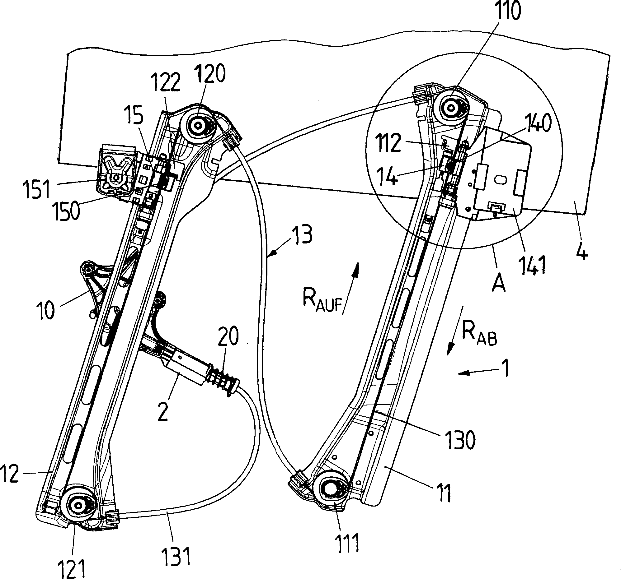
Die
Verstellvorrichtung
Die
Verstellvorrichtung
Das
Zugmittel
Das
Zugmittel
Im
Betrieb der Antriebseinheit
In
Soll
die Fensterscheibe
Um
insbesondere bei einer rahmenlosen Fahrzeugtür eine Kurzhubfunktion
zur Verfügung zu stellen, ist es jedoch erforderlich, dass
die Fensterscheibe
Hier
greift die vorliegende Erfindung ein. Der Erfindung zugrunde liegender
Gedanke ist, zu Beginn des Verstellvorgangs zum Verfahren der Mitnehmer
Varianten
der Vorspanneinrichtung sind in
Für
eine Kurzhubfunktion einer rahmenlosen Fahrzeugtür ist
die Vorspanneinrichtung
Eine
alternative Ausgestaltung ist in
Bei
der weiteren Ausgestaltung gemäß
Eine
Variante der Ausführungsform gemäß
Bei
der Ausgestaltung gemäß
Bei
der Ausführungsform gemäß
Bei
den vorangehend geschilderten Ausführungsbeispielen ist
ein vorspannendes Element
Eine
letzte Ausführungsform ist in der schematischen Ansicht
gemäß
Die
vorangehend geschilderten Ausführungsformen zeigen eine
Vorspanneinrichtung
Die Erfindung ist nicht auf die vorangehend geschilderten Ausführungsbeispiele beschränkt, sondern lässt sich auch in gänzlich anderer Form verwirklichen. Wesentlich hierbei ist, dass zwischen einem Mitnehmer und einer Führungsschiene in einer Endposition eine Vorspanneinrichtung wirkt, die derart vorspannend auf den Mitnehmer einwirkt, dass bei Einleiten eines Verstellvorganges aus der Endposition eine zusätzliche Verstellkraft auf den Mitnehmer ausgeübt wird.The Invention is not on the above-described embodiments limited, but can also be in total realize another form. Essential here is that between a driver and a guide rail in an end position a pretensioning device acts, which acts on the driver in a pretensioning manner, that when initiating an adjustment from the end position a additional adjusting force exerted on the driver becomes.
- 11
- Verstellvorrichtungadjustment
- 1010
- Antriebseinheitdrive unit
- 11, 1211 12
- Führungsschieneguide rail
- 110, 120110 120
- Umlenkelementdeflecting
- 111, 121111, 121
- Umlenkelementdeflecting
- 112, 122112 122
- Anschlagattack
- 1313
- BowdensystemBowden system
- 130130
- Seilrope
- 131131
- BowdenrohrBowden
- 14, 1514 15
- Mitnehmertakeaway
- 140, 150140 150
- Seilnippelcable nipple
- 141, 151141 151
- Halteelementretaining element
- 142142
- Bolzenbolt
- 143143
- Hakenhook
- 22
- SeillängenausgleichsvorrichtungCable length compensating device
- 2020
- Elastisches Elementelastic element
- 33
- Vorspanneinrichtungbiasing means
- 310310
- Zugfedermainspring
- 311311
- Halteelementretaining element
- 312312
- Anschlagelementstop element
- 320320
- Druckfedercompression spring
- 321321
- Anschlagbolzenstop pin
- 322322
- Zylindercylinder
- 330330
- SchenkelfederLeg spring
- 330a, 330b330a, 330b
- Schenkelleg
- 331, 331'331 331 '
- Halteelementretaining element
- 332332
- Hakenelementhook element
- 333333
- Befestigungattachment
- 334334
- Halterungbracket
- 340, 341340 341
- Magnetmagnet
- 350350
- Gasfedergas spring
- 351351
- Hebellever
- 352352
- Drehachseaxis of rotation
- 360360
- Blattfederleaf spring
- 361361
- Anschlagbolzenstop pin
- 362362
- Dämpfungselementdamping element
- 364, 365364, 365
- Aufnahmeadmission
- 44
- Fensterscheibewindowpane
- AA
- Ausschnittneckline
- RAB R AB
- Abwärtsrichtungdownward direction
- RAUF R ON
- Aufwärtsrichtunguplink
ZITATE ENTHALTEN IN DER BESCHREIBUNGQUOTES INCLUDE IN THE DESCRIPTION
Diese Liste der vom Anmelder aufgeführten Dokumente wurde automatisiert erzeugt und ist ausschließlich zur besseren Information des Lesers aufgenommen. Die Liste ist nicht Bestandteil der deutschen Patent- bzw. Gebrauchsmusteranmeldung. Das DPMA übernimmt keinerlei Haftung für etwaige Fehler oder Auslassungen.This list The documents listed by the applicant have been automated generated and is solely for better information recorded by the reader. The list is not part of the German Patent or utility model application. The DPMA takes over no liability for any errors or omissions.
Zitierte PatentliteraturCited patent literature
- - DE 202005019562 U1 [0003] - DE 202005019562 U1 [0003]
- - DE 202005018565 U1 [0027] - DE 202005018565 U1 [0027]
Claims (9)
Priority Applications (1)
| Application Number | Priority Date | Filing Date | Title |
|---|---|---|---|
| DE200820009820 DE202008009820U1 (en) | 2008-07-18 | 2008-07-18 | Adjustment device for an adjustment part of a motor vehicle |
Applications Claiming Priority (1)
| Application Number | Priority Date | Filing Date | Title |
|---|---|---|---|
| DE200820009820 DE202008009820U1 (en) | 2008-07-18 | 2008-07-18 | Adjustment device for an adjustment part of a motor vehicle |
Publications (1)
| Publication Number | Publication Date |
|---|---|
| DE202008009820U1 true DE202008009820U1 (en) | 2009-12-03 |
Family
ID=41397019
Family Applications (1)
| Application Number | Title | Priority Date | Filing Date |
|---|---|---|---|
| DE200820009820 Expired - Lifetime DE202008009820U1 (en) | 2008-07-18 | 2008-07-18 | Adjustment device for an adjustment part of a motor vehicle |
Country Status (1)
| Country | Link |
|---|---|
| DE (1) | DE202008009820U1 (en) |
Cited By (3)
| Publication number | Priority date | Publication date | Assignee | Title |
|---|---|---|---|---|
| DE102010040047B4 (en) | 2010-08-31 | 2019-12-05 | Audi Ag | Carrier for a cable window lifter for motor vehicles |
| DE102010064673B3 (en) | 2010-08-31 | 2023-06-01 | Audi Ag | Driver for a cable window lifter for motor vehicles |
| DE102023203455A1 (en) * | 2023-04-17 | 2024-04-25 | Brose Fahrzeugteile Se & Co. Kommanditgesellschaft, Bamberg | Window lifter assembly and door module of a motor vehicle |
Citations (2)
| Publication number | Priority date | Publication date | Assignee | Title |
|---|---|---|---|---|
| DE202005018565U1 (en) | 2005-11-25 | 2007-04-05 | Brose Fahrzeugteile Gmbh & Co. Kommanditgesellschaft, Coburg | Device for rope length compensation of a Bowden cable system |
| DE202005019562U1 (en) | 2005-12-09 | 2007-04-19 | Brose Fahrzeugteile Gmbh & Co. Kommanditgesellschaft, Coburg | Door for motor vehicle has window drive with motor actuating cable drum and with Bowden casing for guiding cable |
-
2008
- 2008-07-18 DE DE200820009820 patent/DE202008009820U1/en not_active Expired - Lifetime
Patent Citations (2)
| Publication number | Priority date | Publication date | Assignee | Title |
|---|---|---|---|---|
| DE202005018565U1 (en) | 2005-11-25 | 2007-04-05 | Brose Fahrzeugteile Gmbh & Co. Kommanditgesellschaft, Coburg | Device for rope length compensation of a Bowden cable system |
| DE202005019562U1 (en) | 2005-12-09 | 2007-04-19 | Brose Fahrzeugteile Gmbh & Co. Kommanditgesellschaft, Coburg | Door for motor vehicle has window drive with motor actuating cable drum and with Bowden casing for guiding cable |
Cited By (3)
| Publication number | Priority date | Publication date | Assignee | Title |
|---|---|---|---|---|
| DE102010040047B4 (en) | 2010-08-31 | 2019-12-05 | Audi Ag | Carrier for a cable window lifter for motor vehicles |
| DE102010064673B3 (en) | 2010-08-31 | 2023-06-01 | Audi Ag | Driver for a cable window lifter for motor vehicles |
| DE102023203455A1 (en) * | 2023-04-17 | 2024-04-25 | Brose Fahrzeugteile Se & Co. Kommanditgesellschaft, Bamberg | Window lifter assembly and door module of a motor vehicle |
Similar Documents
| Publication | Publication Date | Title |
|---|---|---|
| WO2016142520A1 (en) | Adjustment device with a closure flap adjustable in the manner actuated by an external force | |
| WO2010063628A1 (en) | Window lifter assembly | |
| DE102020113726A1 (en) | Door opener with push chain | |
| DE202008017983U1 (en) | Covering device for the vehicle interior | |
| EP1641993B1 (en) | Deflection device for a motor vehicle window lift | |
| DE102025103059A1 (en) | Tensioning device for a window regulator | |
| DE102012015650A1 (en) | Drive arrangement for the adjustment of a flap of a motor vehicle | |
| DE102008026707A1 (en) | Rotary shaft arrangement for a gate, in particular for a roller door, and such a gate | |
| DE202008009820U1 (en) | Adjustment device for an adjustment part of a motor vehicle | |
| DE102008031467A1 (en) | Adjusting device i.e. cable-controlled window lifter, for adjusting window pane of frame less vehicle door in motor vehicle, has drive unit reducing length of rope loop of mechanism in phase of adjusting process of adjustment part | |
| WO2007107390A1 (en) | Fitting for a window or door | |
| EP1913221B1 (en) | Force transmission element, window lifter and motor vehicle door with a window lifter | |
| DE102008011369A1 (en) | Fixing mechanism for e.g. hydraulically damped traction unit tensioning device, of motor vehicle, has fixing point for fixing traction-unit-tensioning devices, and another fixing point for fixing lever units | |
| DE102004062167B4 (en) | Window system | |
| DE202007003538U1 (en) | Furniture | |
| DE10145180B4 (en) | Adjustable driver for connecting a window pane to a motor vehicle window lifter | |
| DE102020113727A1 (en) | Door stand with detachable bracket | |
| DE102008012434A1 (en) | Module assembly for installation in a motor vehicle | |
| DE102013215716A1 (en) | Flap mechanism of a building | |
| DE102008031466B4 (en) | Adjustment device for an adjustment part of a motor vehicle | |
| DE202006018071U1 (en) | Motor vehicle window lifter for adjusting a window pane of a motor vehicle | |
| DE102016112966A1 (en) | Closure device with locking hook and movable carriage | |
| DE10339506B4 (en) | lifting door | |
| EP3725992A1 (en) | Drive | |
| EP3656958A1 (en) | Auxiliary drive comprising a damping device for a motor-driven gate leaf, and a gate, the rotor blade of which is equipped with an auxiliary drive that contains a damping device |
Legal Events
| Date | Code | Title | Description |
|---|---|---|---|
| R207 | Utility model specification |
Effective date: 20100107 |
|
| R150 | Term of protection extended to 6 years | ||
| R150 | Term of protection extended to 6 years |
Effective date: 20111130 |
|
| R151 | Term of protection extended to 8 years | ||
| R151 | Term of protection extended to 8 years |
Effective date: 20140807 |
|
| R081 | Change of applicant/patentee |
Owner name: BROSE FAHRZEUGTEILE GMBH & CO. KOMMANDITGESELL, DE Free format text: FORMER OWNER: BROSE FAHRZEUGTEILE GMBH & CO. KOMMANDITGESELLSCHAFT, HALLSTADT, 96103 HALLSTADT, DE |
|
| R082 | Change of representative |
Representative=s name: MAIKOWSKI & NINNEMANN PATENTANWAELTE PARTNERSC, DE |
|
| R079 | Amendment of ipc main class |
Free format text: PREVIOUS MAIN CLASS: E05F0015160000 Ipc: E05F0015686000 |
|
| R158 | Lapse of ip right after 8 years |